

Page 1
C 451B
2895Z00..
Last modification: page 4 new, Letzte Änderung: Seite 4 neu Issue / Ausgabe 6/2002
C451B: 2895Z0001 C451B/ST: 2895Z0011
6.1
6
9
1.2
1
1.1
10
7
3.4
10
3.5
3.1
5
3.2
4
3
2
11
3.3
PLEASE ALSO SEE PAGE 4! BITTE AUCH SEITE 4 BEACHTEN!
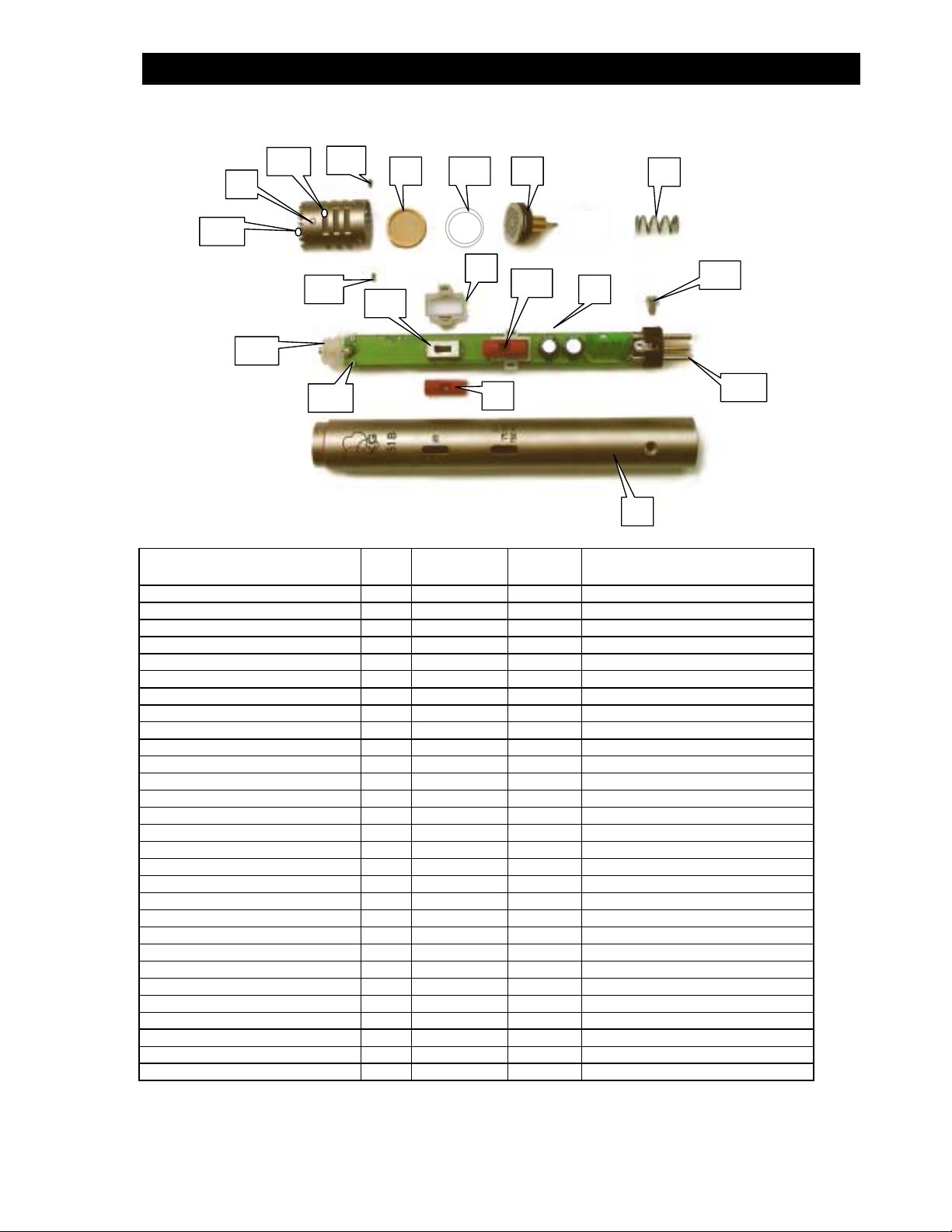
Description Pos. Part Nbr.
Best.-Nr.
Cap, complete with grids 1 2895M0501 1 Kappe, komplett mit Gittern
Grid sleeve 1.1 2895Z0801 1 Gitterhülse
Top grid 1.2 2895Z0701 1 Gitter oben
Housing, new version 2 289 5Z0501 1 Gehäuse, neue Ausfühung
Housing, old version 2 2895Z2501 (1) Gehäuse, alte Ausführung
Printed circuit board, complete 3 2895M0101 1 Print, komplett
Pad switch 3.1 0040E0186 1 Dämpfungsschalter
Bass switch 3.2 0040E0132 1 Bass – Schalter
Connector 3.3 0016E0346 1 Steckereinsatz
Contact carrier 3.4 2895M0201 1 Kontaktträger
Screw for contact carrier 3.5 0099N1402 2 Schraube für Kontaktträger
Switch cover 4 243 9Z2103 2 Schalterblende
Holder 5 2439Z2903 2 Stütze
Electrode, complete 6 2895M0601 1 Elektrode, komplett
Insulation sleeve 6.1 223 0Z2801 1 Distanzhütchen
Membrane, complete 7 2230M0901 1 Membrane, komplett
Insulation strip 8* 2895Z1502 1 Isolationsstreifen
Spring 9 289 5Z1202 1 Feder
Screw M1,4x4 10 0070N1403 4 Schraube M1,4x4
Screw M2,5x6 11 0966D2507 1 Schraube M2,5x6
Stand adapter SA40 -- 6001H0311 1 Stativanschluß SA40
Windshield W90 -- 2496Z0001 1 Windschutz W90
Stereo bar H50 **) 6000H0571 1 Stereoschiene H50
Carrying case -- 1605P0003 1 Zippetui
Upper insert for case -- 8998P0025 1 Einlage oben für Etui
Lower insert for case -- 8998P0021 1 Einlage unten für Etui
Case for stereo version -- 3822P0001 1 Koffer für Stereoversion
Upper insert for stereo version -- 8998P0069 1 Einlage oben für Stereoversion
Lower insert for stereo version -- 8998P0086 1 Einlage unten für Stereoversion
*) see picture on page 2. **) used for the stereo version C451B/ST only. Available as sales item.
*) siehe Abbildung auf Seite 2. **) nur für Stereoversion C451B/ST. Teil ist als Vertriebsartikel erhältlich.
Quant.
Stück
Bezeichnung
page / Seite 1 of/von 5
Page 2
C 451B
2895Z00..
How to dismantle the capsule side:
For access to the capsule elements or for replacing the cap hold microphone in one hand with the thumb
pressing firmly
be held in p la ce. No w undo the four s crew s 1 0 . Att ention, da nger
1. Otherwise the spring 9 will cause the cap to suddenly come off when loosing the fourth screw causing
damage or injuries. Once the screws 10 are removed, slowly and gently release the cap 1 from the housing
2 and take off cap with capsule assembly. The electrode 6 can be pulled out from the housing by spring 9.
Please never touch the surface of the electrode with bare fingers and prevent any direct mechanical
contact. The membrane 7 lie s loosely in t he cap 1 and it 's surface m ust never be touched. Take the part
only with utmost care on the circumference of the gold plated holder ring using a fine sized pair of
tweezers. Take care that the ring is not bent.
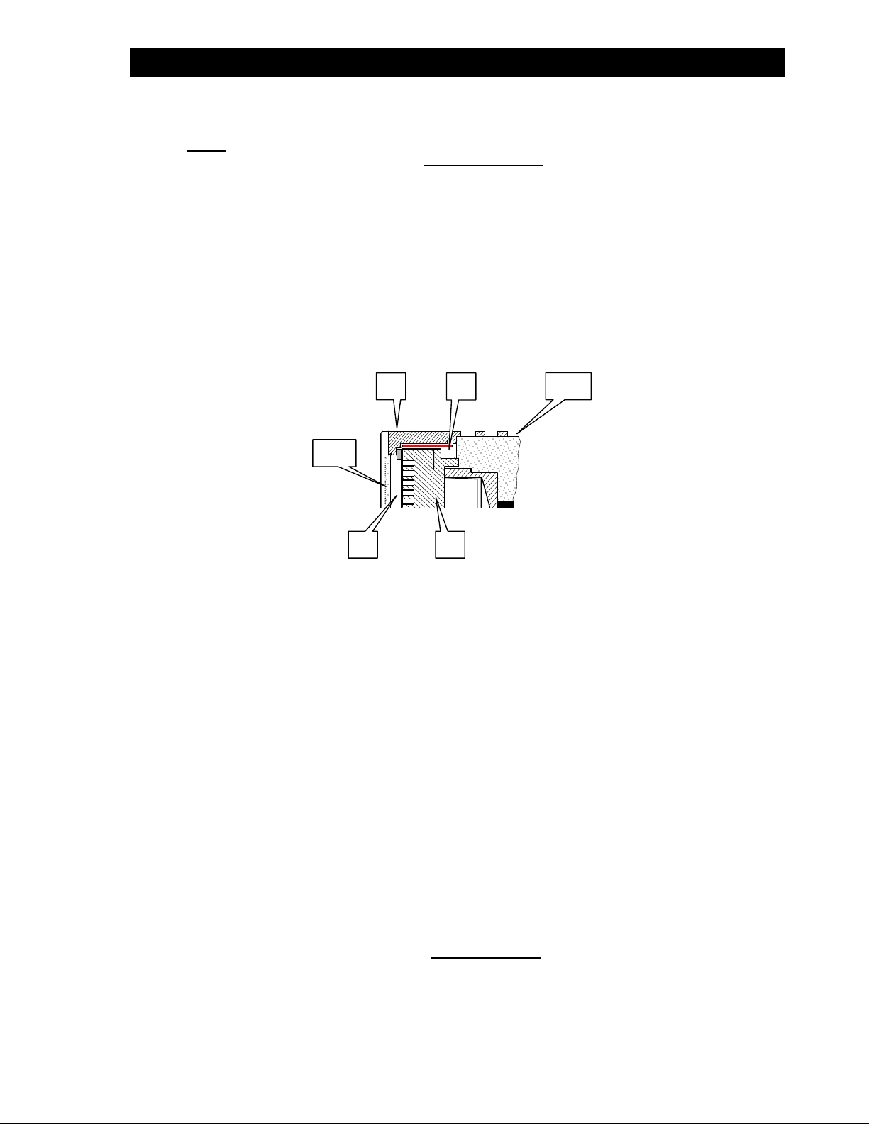
Inside the front portion of the cap 1 a plastic insulation strip 8 is inserted at the area where the high
impedance elements of the capsule are close to the cap's inner wall (Fig. 1). When replacing the cap this
insulation strip either has to be renewed or taken out from the former cap and used again if not
mechanically damaged. The strip 8 is not contained in spare part 1.
Mounting the insulation strip 8 has to be done very carefully. If fitted correctly the strip shall perfectly cling
to the inner wal l of the ca p. O therwise p roper in sertion of membra ne and e lectro de will no t be p ossible. It
may be easier to put the membrane 7 in place first and than wrap the strip ove r the me mbrane ring. If not
carefully done the danger of accidental damage to the membrane foil however is high.
The cap 1 already contains top grid 1.2 and grid sleeve 1.1. The latter is secured to the cap housing with a
two compone nt c ondu ctiv e ad hesi ve. If eve r po ssib le t his pr ocedur e shou ld be carr ied out when f ixing ne w
grid sleeves.
How to remove the amplifier board
against the top end of the capsule. The cap is spring loaded and needs quite some force to
: During t h is job, neve r r e lea se the cap
1
1.2
Fig. 1
8
6 7
1.1
If only the printed circuit board or parts of it need replacement, it is not necessary to remove the cap.
Press the microphone with it's connector end firmly to a plain surface against the force of the spring. Then
remove screw and p ull out t he board 3. When rea ssembl ing the cap sule cont act sleeve wi ll find it' s way t o
the capsule's contact pin simply by pushing the board home. Now press board into housing and fasten
screw 11. For replacing the contact carrier 3.4 remove all solder from the joint between capsule connector
and board, undo screws 3.5 and pull off the carrier. Please also note the hints on page 4.
Other parts than those mentioned in the parts list are not available.
***********
Zerlegen des Kapselteiles
Um an die Teile der Kapsel zu gelangen, oder zum Tausch der Kappe 1 halten Sie das Mikrofon in einer
Hand und drücken mit dem Daumen fest gegen die Frontseite der Kappe. Die Kappe ist durch eine Feder 9
mechanisch vorgespan nt und eine größere Kraft ist notwendig, um sie in der ursprü nglichen Position zu
halten. Nun löse n Sie die vier Schrauben 10. Ac htung, Gefahr
Kappe 1 auslassen. Andernfalls kann durch die Feder 9 nach lösen der vierten Schraube die Kappe plötzlich
weggeschleudert werden, was Beschädigungen oder Verletzungen zur Folge haben kann. Nachdem die
Schrauben 10 entfernt wurden, lassen Sie die Kappe 1 langsam und vorsichtig aus und nehmen Sie diese
mit den Teilen der Kapsel vom Gehäuserohr 2 ab. Die Elektrode 6 kann an der Feder 9 aus der Kappe
gezogen werden. Berühren Sie bitte niemals die Elektrodenfläche mit bloßen Fingern und vermeiden Sie
: Während dieser Tätigkeit niemals die
page / Seite 2 of/von 5
Page 3

C 451B
2895Z00..
überhaupt jeg lichen mechanisc hen Kontakt. Die M embrane 7 liegt lose in der Kappe und ihre Oberflä che
darf niemals berührt werden. Nehmen Sie den Teil mit höchstmöglicher Vorsicht und nur am Rand des
Membranringes, ohne diesen zu verbiegen.
Im Inneren des vorderen Teiles der Kappe 1 ist ein Isolationsstreifen 8 eingelegt, wo die hochohmigen
Teile der Kapsel nahe zur Innenwandung der Kappe stehen (Fig. 1 auf Seite 2). Beim Tausch der Kappe 1
muß dieser Streifen unbedingt entweder ersetzt, oder jener aus der zu tauschenden Kappe wieder
verwendet werden. Er ist nicht in der Ersatzkappe 1 enthalten.
Das Einlegen dieses Streifens hat sehr sorgfältig zu erfolgen. Der Streifen muß sich über seine gesamte
Fläche an die Innenwandung der Kappe schmiegen. Dieser Vorgang wird erleichtert, wenn zuerst die
Membran 7 eingelegt und der Streifen dann um den Membranring geschlungen wird. Allerdings steigt
damit die Gefahr einer unab sichtlichen Beschädigung der Membr ane.
Die Kappe 1 enthält bereits Gitter 1.2 und Gitterhülse 1.1. Letztere ist mit leitfähigem Zweikomponentenkleber an der Kappe angeheftet. Falls eine neue Gitterhülse 1.1 eingesetzt wird, sollte diese Klebung
ebenfalls angebracht werden.
Tausch des Verstärkerprints
Falls lediglich der Verstärker oder Teile davon getauscht werden sollen, ist es nicht notwendig die Kappe 1
zu entfernen. Pressen Sie das Mikrofon mit dem Steckerende fest gegen eine plane Oberfläche gegen die
Kraft der Feder und lösen Sie die Schraube. Ziehen Sie den Verstärker 3 aus dem Gehäuse. Um den
Kontaktträger 3.4 zu ersetzen, entfernen Sie sorgfältig das Lötzinn von der Verbindungsstelle zwischen
Kapselkontakt und Print, lö sen Sie die beide n Schrauben 3.5 und ziehen Sie d en Kontaktträge r ab. Bitte
beachten Sie auch die Hinweise auf Seite 4.
Andere Teile als in der Stückliste angegeben, sind nicht erhältlich.
***********
Technical Specs
Transducer type: backelectret pressure gradient con denser capsule
Polar pattern: cardioid
Transmission range: 20...20.000 Hz
Sensitivity, unloaded: 9,0 mV/Pa (-41 dB)
Capsule capacity: 36 pF
Impedance: 200 Ohms @ 100...20.000 Hz
Nominal load: > 2.000 Ohms
Equivalent noise level: ... dBA DIN 45412
Weighted noise level: ... µVeff DIN45412, IEC 651
Current drain: ... mA @ 48 Volts
Temperature range: -10°C ... +60°C
Rel. humidity: <99% @ +20°C (68°F); <95% @ +60°C
Weight: 125 g
Complies with EN50082-1 (1997) at criterion A: S/N > 15 dBA
Technische Daten
Wandlertype: Backelectret Druckgradienten - Kondensatorkapsel
Richtcharakteri st ik: Cardioide
Übertragungsbereich: 20...20.000 Hz
Leerlaufübertragungsfaktor: 9,0 mV/Pa (-41 dB)
Kapselkapazität: 36 pF
Impedanz: 200 Ohms @ 100...20.000 Hz
Nennbelastbarkeit: > 2.000 Ohms
Äquivalentschalldruckpegel: ... dBA DIN 45412
Störspannung, bewertet: ... µVeff DIN45412, IEC 651
Stromaufnahme: ... mA @ 48 Volts
Temperaturbereich: -10°C ... +60°C
Rel. Feuchte: <99% @ +20°C (68°F); <95% @ +60°C
Gewicht: 125 g
Entspricht EN50082-1 (1997) bei Bewertungskriterium A: S/N > 15 dBA
page / Seite 3 of/von 5
Page 4

C 451B
2895Z00..
This insulation bushing
has the part number
2895Z0901 and is used in
the former version o f the
contact carrier
2895M0201. It is made of
transparent plastic
material. The part can
only be used together
with the housing tube
2895Z2501.
Diese Isolierhülse hat d i e
Teilenummer 2895Z0901,
wird in der früheren
Version des Kontaktträgers 2895M0201
verwendet und ist aus
weißem Kunststoff
gefertigt. Dieser Teil ist
nur zusammen mit
Hüllrohr 2895Z2501 zu
verwenden.
This insulation bushing
has the part number
2895Z0902 and is used in
the new ver sion of the
contact carrier
2895M0201. It is made of
white plastic material. The
part can only be used
together with the housing
tube 2895Z0501.
Diese Isolierhülse hat d i e
Teilenummer 2895Z0902,
wird in der neuen Version
des Kontaktträgers
2895M0201 verwendet
und ist aus weißem
Kunststoff gefertigt.
Dieser Teil ist nur
zusammen mit Hüllrohr
2895Z0501 zu
verwenden.
page / Seite 4 of/von 5
Page 5

C 451B
2895Z00..
Schematics
For better understanding of the technical design
aspects the schematics is shown below. Other parts
than those mentioned in the part list are not available.
Schaltung
Zum Verständnis der technischen Zusammenhänge ist
hier die Schaltung gezeigt. Andere Teile als in der
Stück liste angegeben, sind nicht erhältlich.
_____________________________________________________________________________________
AKG Acoustics GmbH, A Har man International Com p any, Lemböckgasse 21-25, A-1230 Wien, Austria
Phone: (+431) 86654-1519, Fax: (+431) 86654-1514, e-mail: service@akg.com, www.akg.com
page / Seite 5 of/von 5
 Loading...