

AKG C-451-B Owners manual
C 451B
Bedienungshinweise . . . . . . . . . . . . . . . . . . S. 2
Bitte vor Inbetriebnahme des Gerätes lesen!
User Instructions . . . . . . . . . . . . . . . . . . . . p. 11
Please read the manual before using the equipment!
Mode d’emploi . . . . . . . . . . . . . . . . . . . . . . p. 20
Veuillez lire cette notice avant d’utiliser le système!
Istruzioni per l’uso . . . . . . . . . . . . . . . . . . . p. 29
Prima di utilizzare l’apparecchio, leggere il manuale!
Modo de empleo . . . . . . . . . . . . . . . . . . . . p. 38
Antes de utilizar el equipo, lea por favor el manual!
Instruções de uso . . . . . . . . . . . . . . . . . . . p. 47
Favor leia este manual antes de usar o equipamen
to!
1 Sicherheitshinweis/Beschreibung
1.1 Sicherheitshinweis
1.2
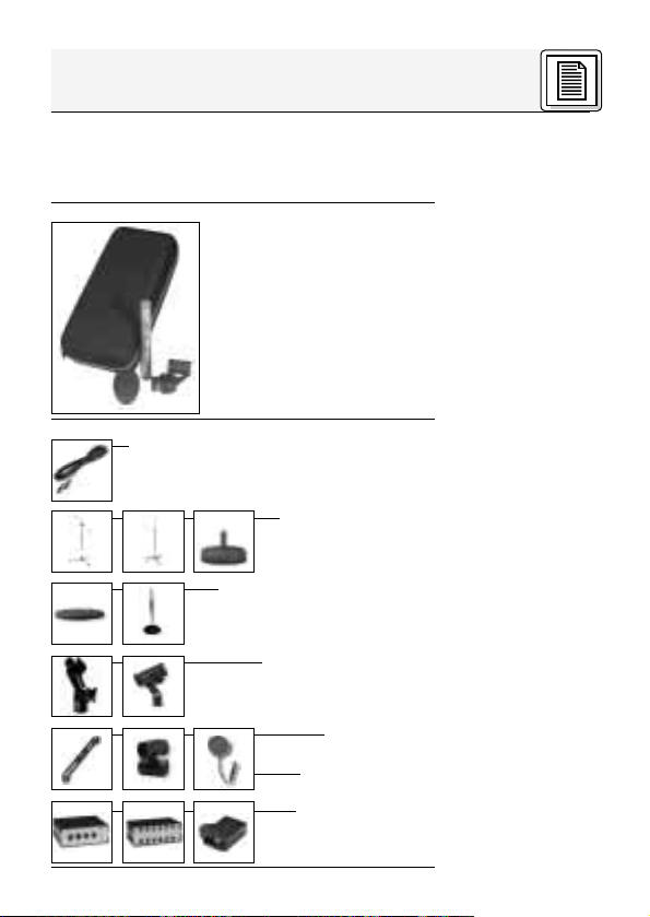
Lieferumfang
1.3 Empfohlenes
Zubehör
Überprüfen Sie bitte, ob das Gerät, an das Sie das
Mikrofon anschließen möchten, den gültigen Sicherheitsbestimmungen entspricht und mit einer
Sicherheitserdung versehen ist.
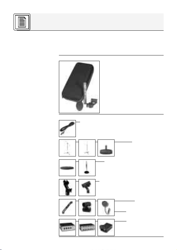
• 1 C 451B mit individueller
Frequenzkurve
• 1 SA 40
• 1 W 90
• 1 Etui
Kontrollieren Sie bitte, ob die
Verpackung alle oben angeführten Teile enthält. Falls
etwas fehlt, wenden Sie sich
bitte an Ihren AKG-Händler.
• Mikrofonkabel MK 9/10: 10 m 2-polig
geschirmtes Kabel mit XLR-Stecker
und XLR-Kupplung
• Bodenstative
ST 102, ST 200,
ST 305
• Tischstative ST 45, ST 12
• Stativanschlüsse SA 18/1B,
SA 38/H
• Halterungen
H 50, H 300
• Pop-Filter PF 80
• Phantomspeisegeräte N 62 E,
N 66 E, B 18
2

1 Beschreibung
• Akustik der legendären CK 1
• Robuste Mechanik
• Geringes Eigenrauschen
• Geringer Strombedarf
• Hohe Betriebssicherheit
• Trafolose Ausgangsstufe
• Speisung durch jede Phantomspeiseeinrichtung nach DIN 45 596 / IEC 268-15
• Eingebaute, schaltbare Vordämpfung um
10 dB oder 20 dB
• Eingebautes, schaltbares Bassfilter mit
Einsatzpunkt des Filters bei 75 Hz oder
150 Hz (12 dB/Oktave)
Das C 451B ist die moderne Neuauflage des
heute schon historischen AKG Kondensatormikrofons C 451EB + CK 1. Der Aufbau ist allerdings nicht modular, um die deutlichen mechanischen Nachteile, die durch den modularen
Aufbau bestanden, vermeiden zu können. Das
Haupteinsatzgebiet sind alle Anwendungen, bei
denen es auf die hochpräzise Übertragung von
Schallereignissen, insbesondere von transienten
Signalanteilen, ankommt.
Das Mikrofon ist aufgrund seiner leichten
Membrane weitestgehend unempfindlich gegen
Hantierungsgeräusche. Weitere Merkmale sind
das Ganzmetallgehäuse und dadurch die geringe
HF-Störanfälligkeit sowie der problemlose
Betrieb unter nahezu allen Bedingungen aufgrund
der verläßlichen Konstruktion.
Die einschaltbare Vordämpfung um 10 dB oder
20 dB ist insbesondere im Zusammenhang mit
hohen Schalldrücken (z. B. bei Verwendung im
Nahbereich von energiereichen Schallquellen)
und bei Eingangsstufen von Verstärkern oder
Mischpulten mit begrenztem maximalen
Eingangspegel von Vorteil, da sonst bereits eine
1.4 Besondere
Merkmale
1.5 Kurzbeschreibung
3

1 Beschreibung
Übersteuerung dieser angeschlossenen Stufen
erfolgt, ohne daß die Aussteuerfähigkeit des
Mikrofons voll genutzt wird.
Die am Mikrofon einschaltbare Bassabschwächung hilft zusätzlich, Verzerrungen bei
tiefsten Frequenzen hintanzuhalten, die in unkontrollierter Weise z.B. durch Rumpel- oder
Windgeräusche auftreten können. Die Steilheit
des Filters beträgt ca. 12 dB/Oktave, wobei die
Eckfrequenz (-3 dB-Punkt) wahlweise bei 75 Hz
oder 150 Hz liegt.
4

2 Anschluss
Das C 451B ist ein Kondensatormikrofon und
benötigt daher eine Stromversorgung.
Das Mikrofon besitzt einen symmetrischen Ausgang mit 3-poligem XLR-Stecker:
Stift 1 = Masse
Stift 2 = Tonader (inphase)
Stift 3 = Tonader (return)
Sie können das Mikrofon an symmetrische Mikrofoneingänge mit oder ohne Phantomspeisung
anschließen. Die Phantomspeisegeräte von AKG
erlauben Ihnen auch, das Mikrofon an asymmetrische Eingänge anzuschließen.
1. Schließen Sie das Mikrofon mit einem XLR-
Mikrofonkabel (z.B. dem optionalen MK 9/10
von AKG) an einen symmetrischen XLR-Mikrofoneingang mit Phantomspeisung an.
2. Schalten Sie die Phantomspeisung ein. (Lesen
Sie dazu in der Betriebsanleitung des jeweiligen Gerätes nach.)
2.2
2.3
C 451B
C 451B
Phantom
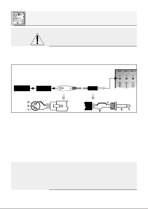
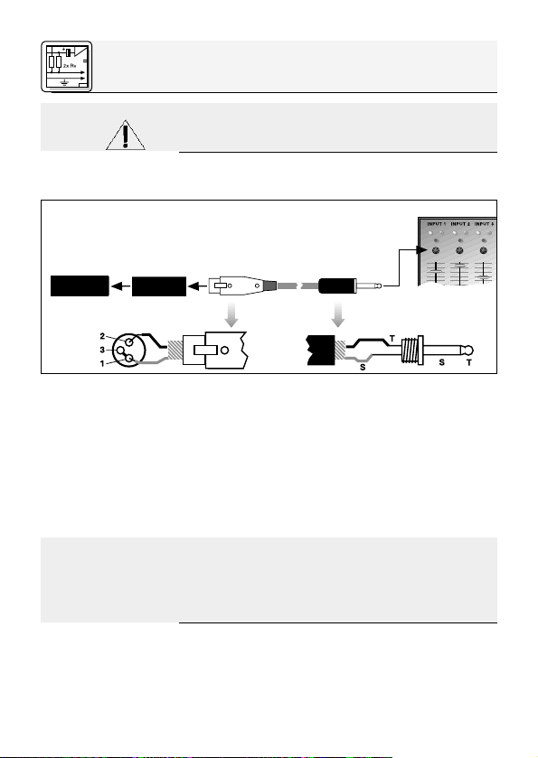
Abb. 1: Anschluss an symmetrischen Eingang
2.1 Allgemeines
Siehe Kapitel 2.2
und 2.3.
2.2 Eingang mit
Phantomspeisung
Siehe Abb. 1.
1. Wenn Ihr Mischpult keine Phantomspeisung
besitzt, schalten Sie zwischen Mikrofon und
Mischpulteingang ein AKG-Phantomspeisegerät (N 62 E, N 66 E, B 18 - optional).
2.3 Eingang
ohne Phantomspeisung
Siehe Abb. 1.
5
2 Anschluss
Wichtig!
2.4
Asymmetrischer
Eingang
C 451B
Phantom
Siehe Abb. 2.
Hinweis:
Wenn Sie andere als die von AKG empfohlenen Speisegeräte verwenden, kann das
Mikrofon beschädigt werden und erlischt
die Garantie.
Die Phantomspeisegeräte von AKG können Sie
auch an einen asymmetrischen Eingang anschließen.
Abb. 2: Anschluss an asymmetrischen Eingang
Verwenden Sie dazu ein Kabel mit XLR-Stecker
(weiblich) und Mono-Klinkenstecker:
1. Verbinden Sie im XLR-Stecker mittels einer
Drahtbrücke Stift 1 mit Stift 3 und mit der
Abschirmung.
2. Verbinden Sie die innere Ader des Kabels mit
Stift 2 des XLR-Steckers und der Spitze des
Klinkensteckers.
Beachten Sie, dass asymmetrische Kabel Einstreuungen aus Magnetfeldern (von Netz- und
Lichtkabeln, Elektromotoren usw.) wie eine Antenne aufnehmen können . Bei Kabeln, die länger
als 5 m sind, kann dies zu Brumm- und ähnlichen
Störgeräuschen führen.
6

3 Anwendung
Das stabförmige Gehäuse, die präzise Akustik,
sowie die Vielzahl an passendem Zubehör von
AKG erlauben eine vielseitige und praxisgerechte
Anwendung des Mikrofons an einem breiten
Spektrum von Instrumenten.
Beachten Sie bitte die folgenden Hinweise, um
Ihr Mikrofon optimal einsetzen zu können.
Mikrofone mit Richtwirkung haben bedingt durch
das akustische Prinzip einen mehr oder weniger
ausgeprägten Naheffekt. Dieser bewirkt eine
besonderen Betonung der tiefen Frequenzanteile,
die mit abnehmendem Mikrofonabstand zur
Schallquelle zunimmt. Hörbar ist diese Betonung
bereits ab etwa 60 cm. Je nach Schallquelle kann
dieser Effekt erwünscht oder auch unerwünscht
sein und ist durch entsprechende Mikrofonplatzierung zu erreichen bzw. auszugleichen.
3.1 Einleitung
3.2 Naheffekt
3.3 Rückkopplung bei
Beschallungsanlagen
Abb. 3: Mikrofonaufstellung für
minimale
Rückkopplung
Die Rückkopplung kommt dadurch zustande,
dass ein Teil des von den Lautsprechern abgegebenen Schalls vom Mikrofon aufgenommen und
verstärkt wieder den Lautsprechern zugeleitet
wird. Ab einer bestimmten Lautstärke (der
7
3 Anwendung
Siehe Abb. 3.
Rückkopplungsgrenze) läuft dieses Signal gewissermaßen im Kreis, die Anlage heult und pfeift
und kann nur durch Zurückdrehen des
Lautstärkereglers wieder unter Kontrolle gebracht
werden.
Um dieser Gefahr zu begegnen, hat das Mikrofon
eine nierenförmige Richtcharakteristik. Das
bedeutet, dass es für Schall, der von vorne (von
der Schallquelle) einfällt am empfindlichsten ist,
während es auf seitlich einfallenden Schall oder
Schall, der von hinten auftrifft (z.B. von Monitorlautsprechern), kaum anspricht.
Minimale Rückkopplungsneigung erreichen Sie,
indem Sie die PA-Lautsprecher vor den
Mikrofonen (am vorderen Bühnenrand) aufstellen.
Wenn Sie Monitorlautsprecher verwenden, lassen
Sie Ihr Mikrofon nie direkt auf die Monitore oder
die PA-Lautsprecher zeigen.
Rückkopplung kann auch durch Resonanzerscheinungen (als Folge der Raumakustik),
besonders im unteren Frequenzbereich, ausgelöst werden, also indirekt durch den Naheffekt.
In diesem Fall brauchen Sie oft nur den
Mikrofonabstand zu vergrößern, um die
Rückkopplung zum Abreissen zu bringen.
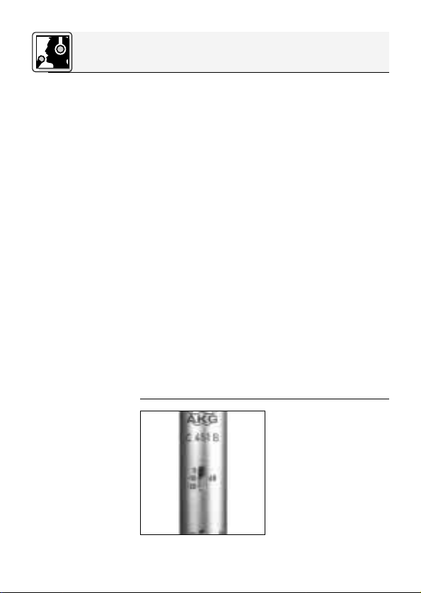
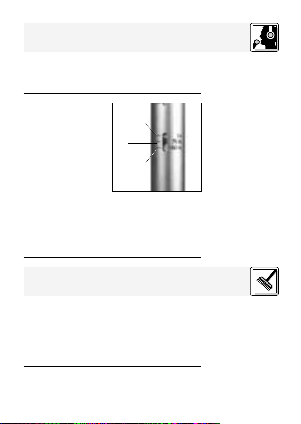
3.4 Vor-
abschwächung
Abb. 4: Schalter
Vorabschwächung
8
Bei besonders lauten
Schallquellen bzw.
besonders kleinen
Aufnahmeabständen
kann der auf die
Membran auftreffende
Schalldruck erheblich
für
werden lassen, daß die nachfolgende
Impedanzwandler-/Verstärkerstufe übersteuert
sein und das elektrische Ausgangssignal
des Wandlers so hoch
3 Anwendung
wird und so zu hörbaren Verzerrungen führt. Zur
Vermeidung dieser Gefahr können Sie am
Mikrofonschaft eine Vorabschwächung um 10 dB
(ca. 1:3) bzw. 20 dB (ca. 1:10) einschalten.
Tieffrequente Rumpeloder Windgeräusche
von normalerweise
nicht als störend wahrgenommenen Quellen
wie Klimaanlagen,
Verkehrslärm,
Gebäudegeräusche,
etc. kommen bei einer
Aufnahme sehr deutlich
zum Vorschein und können deshalb sehr störend
wirken.
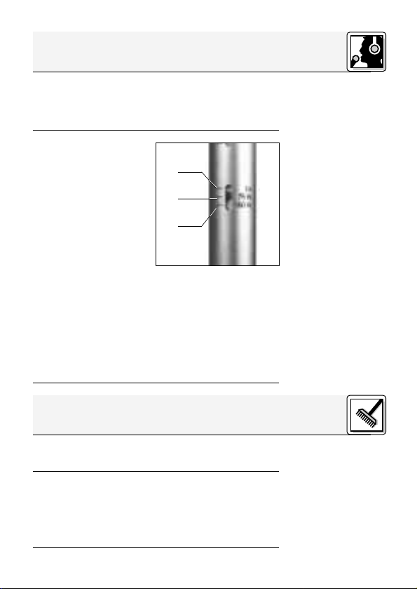
Zur Vermeidung dieser Gefahr können Sie am
Mikrofonschaft ein Tiefenfilter einschalten. Sie
können das Filter je nach Stör- und
Nutzsignalspektrum von der Linearstellung (1) auf
die Grenzfrequenz von 75 Hz (2) oder 150 Hz (3)
einstellen. Die Steilheit des Tiefenfilters beträgt in
beiden Fällen 12 dB / Oktave (ca. 1:4) nach unten.
➊
➋
➌
4 Reinigung
Reinigen Sie die Gehäuseoberfläche des Mikrofons mit (Industire-)Spiritus oder Alkohol.
1. Reinigen Sie den Windschutz mit einer milden
Waschmittellösung.
2. Lassen Sie den Windschutz trocknen.
Sobald der Windschutz trocken ist, können
Sie ihn wieder am Mikrofon anbringen.
3.5 Bassabschwächung
Abb. 5: Schalter für
Bassabschwächung
Siehe Abb. 5.
4.1 Gehäuseoberfläche
4.2 Windschutz
9
5 Technische Daten
Richtcharakteristik: Niere
Übertragungsbereich: 20 – 20.000 Hz ± 1,5 dB von Sollkurve
Empfindlichkeit: 9 mV/Pa = - 41 dBV bez. auf 1V/Pa
Elektrische Impedanz: < 200 Ω
Empfohlene Lastimpedanz: > 1000 Ω
Grenzschalldruck für 0,5% Klirrfaktor: 112 Pa Ⳏ 135 dB SPL (0 dB Abschwächung*)
Äquivalentschalldruckpegel nach DIN 45 412 (A-bew.): 18 dB-A
Dynamikbereich: 117 dB max. (A-bew.)*)
Vorabschwächung: schaltbar auf 0, -10, -20 dB
Bassabschwächung: schaltbar auf linear, 75 Hz, 150 Hz mit 12 dB/Oktave
Speisespannung: 9 – 52 Volt Universalphantomspeisung
Betriebstemperatur: -20°C bis +60°C
Steckeranschluß: 3 pol. XLR-Stecker
Gehäuseoberfläche: seidenglanz vernickelt
Abmessungen: 19 mm ø x 160 mm
Gewicht (netto / brutto): 125 g / 760 g
*) Diese Werte gelten für 48-Volt Phantomspeisung und sind um 2 dB für 24-Volt,
bzw. um 8 dB für 12-Volt Phantomspeisung zu reduzieren.
Dieses Produkt entspricht der Norm EN 50 082-1 (1997), vorausgesetzt, dass
nachgeschaltete Geräte CE-konform sind.
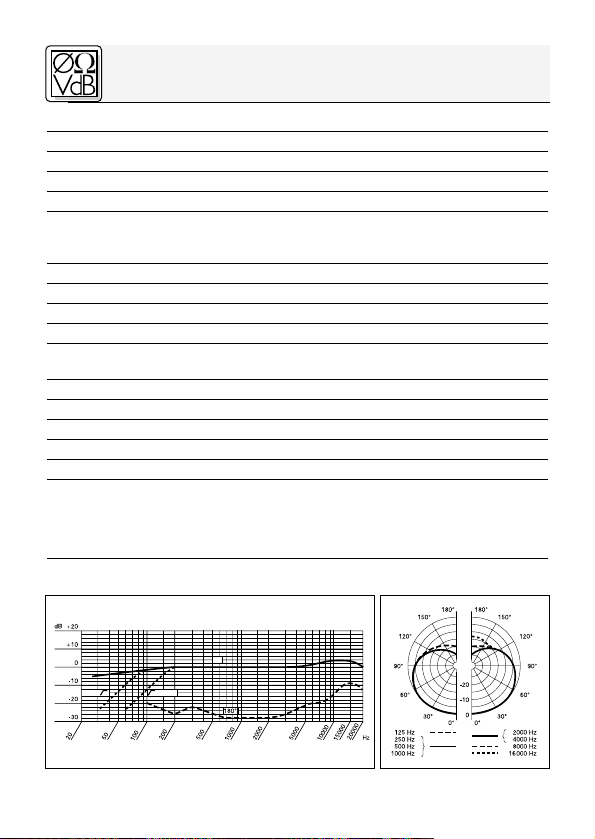
Frequenzkurve Polardiagramm
150 Hz75 Hz
355 Pa Ⳏ 145 dB SPL (10 dB Abschwächung*)
1120 Pa Ⳏ 155 dB SPL (20 dB Abschwächung*)
nach DIN 45 596 / IEC 268-15
0°
10
1 Precaution/Description
Please make sure that the piece of equipment
your microphone will be connected to fulfills the
safety regulations in force in your country and is
fitted with a ground lead.
• 1 C 451B with individual
response curve
• 1 SA 40
• 1 W 90
• 1 zippered carrying bag
Check that the packaging
contains all of the components listed above. Should
anything be missing, please
contact your AKG dealer.
•
MK 9/10 microphone cable: 10-m (30-ft.)
2-conductor shielded cable with male
and female XLR connectors
• ST 102A, ST 200,
ST 305 floor stands
• ST 45, ST 12 table stands
• SA 18/1B, SA 38/H
stand adapters
• H 50, H 300
suspensipons
• PF 80 pop filter
1.1 Precaution
1.2 Unpacking
1.3 Optional
Accessories
• N 62 E, N 66 E,
B 18 phantom
power supplies
11

1 Description
1.4 Features
1.5 Brief
Description
• Same transducer as in the legendary CK 1.
• Rugged construction.
• Low self-noise.
• Low current consumption.
• High reliability.
• Transformerless output stage.
• Operates on phantom power to DIN 45
596/IEC 268-15.
• Built-in, switchable 10-dB or 20-dB preattenuation pad.
• Built-in, switchable 12 dB/octave highpass
filter at 75 Hz or 150 Hz.
The C 451B is a updated rerun of a classic AKG
condenser microphone, the C 451 EB + CK 1.
The new C 451B, however, uses a fixed capsule
to eliminate the mechanical problems of the
original modular design. The microphone is the
perfect choice for any application where sounds,
particularly their transient content, need to be
captured with maximum accuracy.
Owing to its extremely light diaphragm, the
microphone is highly insensitive to handling
noise. An all-metal body provides efficient protection from RF interference and the microphone
is rugged enough to give excellent results even
under very harsh conditions.
A switchable 10-dB/20-dB preattenuation pad
increases the microphone's SPL capability when
close-miking high-energy sound sources or driving preamps or mixers with limited headroom.
A switchable highpass filter at 75 Hz or 150 Hz
prevents low-end distortion that may be caused,
e.g., by rumble or wind noise. The slope of the filter is 12 dB/octave and its corner frequency (3 dB
down point) is selectable at 75 Hz or 150 Hz.
12

2 Interfacing
The C 451B is a condenser microphone and therefore needs a power supply.
The microphone provides a balanced output on a
3-pin male XLR connector:
Pin 1: ground
Pin 2: hot
Pin 3: return
You can connect the microphone to balanced
microphone inputs with or without phantom
power. AKG phantom power supplies allow you
to connect the microphone to unbalanced inputs
as well.
1. Use an XLR cable (e.g., the optional MK 9/10
from AKG) to connect the microphone to a
balanced XLR input with phantom power.
2. Switch the phantom power on. (Refer to the in-
struction manual of the unit to which you
connected your C 451B.)
2.2
2.3
C 451B
C 451B
Phantom
Fig. 1: Connecting to a balanced input.
1. If your mixer provides no phantom power,
connect an optional AKG phantom power
supply (N 62 E, N 66 E, B 18) between the
microphone and the mixer.
2.1 General
Refer to sections
2.2 and 2.3.
2.2 Input with
Phantom Power
Refer to fig. 1.
2.3 Input with
No Phantom
Power
Refer to fig. 1.
13
2 Interfacing
Important!
2.4 Unbalanced
Input
C 451B
Phantom
Refer to fig. 2.
Note:
Using any power supply other than those
recommended by AKG may damage your
microphone and will void the warranty.
You may connect AKG phantom power supplies
to unbalanced inputs, too.
Fig. 2: Connecting to an unbalanced input.
Use a cable with a female XLR connector and TS
jack plug:
1. On the XLR connector, use a wire bridge to
connect pin 1 to pin 3 and the cable shield.
2. Connect the inside wire of the cable to pin 2
on the XLR connector and the tip contact of
the jack plug.
Unbalanced cables may pick up interference from
stray magnetic fields near power or lighting
cables, electric motors, etc. like an antenna. This
may introduce hum or similar noise when you use
a cable that is longer than 16 feet (5 m).
14

3 Application
The rod-shaped body, accurate response, and
many matching accessories from AKG make it
easy to use the microphone to pick up a wide
range of different instruments.
Read the following hints to get the best possible
results.
Owing to their acoustic principle, unidirectional
microphones exhibit what is called "proximity
effect". This means that the low-frequency content
of a sound signal will be progressively boosted as
the microphone is moved closer to the sound
source. Proximity effect begins to become audible
at a working distance of about 2 feet (60 cm).
Depending on the nature of the sound source,
proximity effect may be desirable or a nuisance.
Place the microphone closer to the sound source
to accentuate, or further away to reduce
proximity effect.
3.1 Introduction
3.2 Proximity
Effect
3.3 Feedback in
Live Sound
Situations
Fig. 3: Microphone
placement for
maximum gain
before feedback.
Feedback is the result of part of the sound projected by a speaker being picked up by a microphone, fed to the amplifier, and projected again
by the speaker. Above a specific volume or
“system gain” setting called the feedback
15
3 Application
Refer to fig. 3.
threshold, the signal starts being regenerated
indefinitely, making the sound system howl and
the sound engineer desperately dive for the
master fader to reduce the volume and stop the
howling.
To increase usable gain before feedback, the
microphone has a cardioid polar pattern. This
means that the microphone is most sensitive to
sounds arriving from in front of it (from the sound
source) while picking up much less of sounds
arriving from the sides or rear (from monitor speakers for instance).
To get maximum gain before feedback, place the
main (“FOH”) speakers in front of the microphones (along the front edge of the stage). If you
use monitor speakers, be sure never to point any
microphone directly at the monitors, or at the
FOH speakers.
Feedback may also be triggered by resonances
depending on the acoustics of the room or hall.
With resonances at low frequencies, proximity
effect may cause feedback. In this case, it is often
enough to move away from the microphone a
little to stop the feedback.
Preattenuation
Preattenuation
switch.
16
3.4
Pad
Fig. 4:
If you are miking up an
extremely loud sound
source or have placed
the microphone extremely close to an
instrument, the diaphragm may be exposed to extremely
high sound pressure
levels. As a result, the
electrical output signal of the transducer may
become high enough to overload the subsequent
impedance converter/preamplifier and introduce
3 Application
audible distortion. To minimize the risk of getting
audible distortion, use the preattenuation switch
on the microphone shaft to switch in 10 dB (1:3)
or 20 dB (1:10) of preattenuation.
Low-frequency rumble
or wind noise such as
air conditioning rumble,
traffic noise, structureborne noise, etc. that
usually pass unnoticed
may become a clearly
audible nuisance on a
recording.
To minimize lowfrequency noise, you can switch in the highpass
filter. Depending on the spectra of the wanted
and unwanted signals, set the highpass filter
switch on the microphone shaft from flat (1) to a
corner frequency of 75 Hz (2) or 150 Hz (3). In
either position, the slope of the filter is
12 dB/octave (1:4) downward.
➊
➋
➌
4 Cleaning
Clean the surface of the microphone body with
(methylated) spirits or alcohol.
1. Wash the windscreen in mild soap suds.
2. Allow the windscreen to dry.
You can use the windscreen again as soon as
it has dried completely.
3.5 Highpass
Filter
Fig. 5: Highpass
filter switch.
Refer to fig. 5.
4.1 Body
Surface
4.2 Internal
Windscreen
17
 Loading...