

Page 1
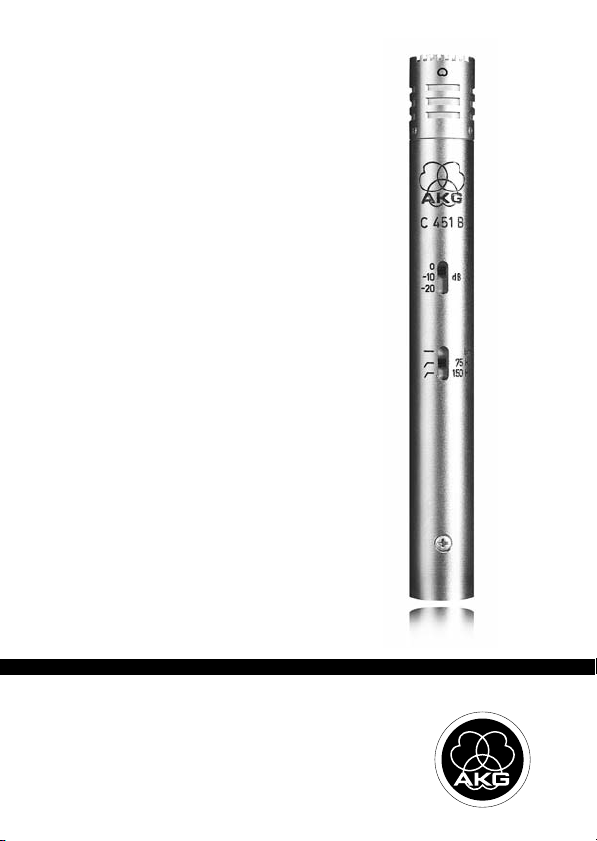
C 451B
BEDIENUNGSANLEITUNG . . . . . . . . . .S. 2
Bitte vor Inbetriebnahme des Gerätes lesen!
USER INSTRUCTIONS . . . . . . . . . . . . . . .p. 12
Please read the manual before using the equipment!
MODE D’EMPLOI . . . . . . . . . . . . . . . . . . . . .p. 22
Veuillez lire cette notice avant d’utiliser le système!
ISTRUZIONI PER L’USO . . . . . . . . . . . . .p. 32
Prima di utilizzare l’apparecchio, leggere il manuale!
MODO DE EMPLEO . . . . . . . . . . . . . . . . . . .p. 42
¡Sirvase leer el manual antes de utilizar el equipo!
INSTRUÇÕES DE USO . . . . . . . . . . . . . . .p. 52
Favor leia este manual antes de usar o equipamento!
Page 2

Inhaltsverzeichnis
Seite
1 Sicherheit und Umwelt ........................................................................3
1.1 Sicherheit ......................................................................................3
1.2 Umwelt ..........................................................................................3
2 Beschreibung ......................................................................................4
2.1 Einleitung.......................................................................................4
2.2 Lieferumfang .................................................................................4
2.3 Optionales Zubehör ........................................................................4
2.4 Besondere Merkmale ......................................................................4
2.5 Kurzbeschreibung...........................................................................5
3 Anschluss............................................................................................6
3.1 Allgemeines ...................................................................................6
3.2 Symmetrischer Eingang mit Phantomspeisung ..................................6
3.3 Symmetrischer Eingang ohne Phantomspeisung ...............................7
3.4 Unsymmetrischer Eingang...............................................................7
4 Anwendung .........................................................................................8
4.1 Einleitung.......................................................................................8
4.2 Naheffekt.......................................................................................8
4.3 Rückkopplung bei Beschallungsanlagen ...........................................8
4.4 Vorabschwächung ..........................................................................9
4.5 Bassabschwächung......................................................................10
5 Reinigung ..........................................................................................10
5.1 Gehäuseoberfläche.......................................................................10
5.2 Windschutz ..................................................................................10
6 Technische Daten ..............................................................................11
2
C 451 B
Page 3
1 Sicherheit und Umwelt
L
• Überprüfen Sie bitte, ob das Gerät, an das Sie das Mikrofon anschließen möchten, den gültigen Sicherheitsbestimmungen entspricht und mit einer Sicherheitserdung versehen ist.
1. Wenn Sie das Gerät verschrotten, trennen Sie Gehäuse,
Elektronik und Kabel und entsorgen Sie alle Komponenten
gemäß den dafür geltenden Entsorgungsvorschriften.
2. Die Verpackung ist wiederverwertbar. Entsorgen Sie die
Verpackung in einem dafür vorgesehenen Sammelsystem.
1.1 Sicherheit
!
L
1.2 Umwelt
C 451 B
3
Page 4
2 Beschreibung
2.1 Einleitung
2.2 Lieferumfang
2.3 Optionales
Zubehör
2.4 Besondere
Merkmale
Vielen Dank, dass Sie sich für ein Produkt aus dem Hause AKG
entschieden haben. Bitte lesen Sie die Bedienungsanleitung
aufmerksam durch, bevor Sie das Gerät benützen, und bewahren Sie die Bedienungsanleitung sorgfältig auf, damit Sie
jederzeit nachschlagen können. Wir wünschen Ihnen viel Spaß
und Erfolg!
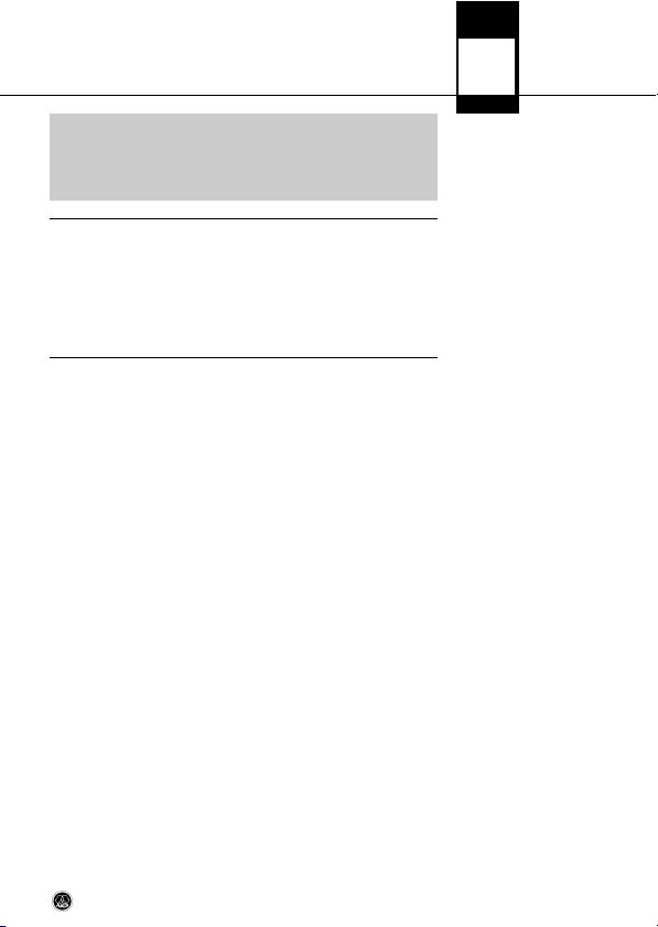
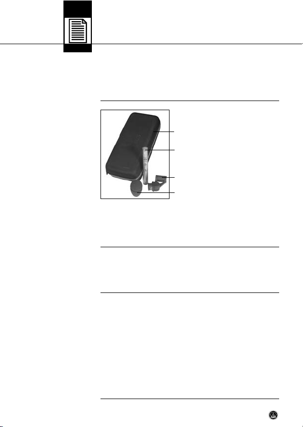
• 1 Soundtool Case (klein)
• 1 C 451B mit individueller Fre-
quenzkurve
• 1 SA 60
• 1 W 90
• Kontrollieren Sie bitte, ob die Verpackung alle oben angeführten Teile enthält. Falls etwas fehlt, wenden Sie sich bitte
an Ihren AKG-Händler.
• Optionales Zubehör finden Sie im aktuellen AKGKatalog/Folder oder auf www.akg.com. Ihr Händler berät
Sie gerne.
• Akustik der legendären CK 1
• Robuste Mechanik
• Geringes Eigenrauschen
• Geringer Strombedarf
• Hohe Betriebssicherheit
• Trafolose Ausgangsstufe
• Speisung durch jede Phantomspeiseeinrichtung nach
IEC 61938
• Eingebaute, schaltbare Vordämpfung um 10 dB oder 20 dB
4
C 451 B
Page 5
2 Beschreibung
• Eingebautes, schaltbares Bassfilter mit Einsatzpunkt des
Filters bei 75 Hz oder 150 Hz (12 dB/Oktave)
Das C 451B ist die moderne Neuauflage des heute schon historischen AKG Kondensatormikrofons C 451EB + CK 1. Der Aufbau ist allerdings nicht modular, um die deutlichen mechanischen Nachteile, die durch den modularen Aufbau bestanden,
vermeiden zu können. Das Haupteinsatzgebiet sind alle Anwendungen, bei denen es auf die hochpräzise Übertragung von
Schallereignissen, insbesondere von transienten Signalanteilen, ankommt.
Das Mikrofon ist aufgrund seiner leichten Membrane weitestgehend unempfindlich gegen Hantierungsgeräusche. Weitere
Merkmale sind das Ganzmetallgehäuse und dadurch die geringe HF-Störanfälligkeit sowie der problemlose Betrieb unter
nahezu allen Bedingungen aufgrund der verlässlichen Konstruktion.
Die einschaltbare Vordämpfung um 10 dB oder 20 dB ist insbesondere im Zusammenhang mit hohen Schalldrücken (z. B. bei
Verwendung im Nahbereich von energiereichen Schallquellen)
und bei Eingangsstufen von Verstärkern oder Mischpulten mit
begrenztem maximalen Eingangspegel von Vorteil, da sonst bereits eine Übersteuerung dieser angeschlossenen Stufen erfolgt, ohne dass die Aussteuerfähigkeit des Mikrofons voll genutzt wird.
Die am Mikrofon einschaltbare Bassabschwächung hilft zusätzlich, Verzerrungen bei tiefsten Frequenzen, die z.B. durch Rumpel- oder Windgeräusche verursacht werden können, zu minimieren. Die Steilheit des Filters beträgt ca. 12 dB/Oktave, wobei
die Eckfrequenz (-3 dB-Punkt) wahlweise bei 75 Hz oder 150 Hz
liegt.
2.5 Kurzbeschreibung
C 451 B
5
Page 6
3 Anschluss
3.1 Allgemeines
Siehe Kapitel 3.2
und 3.3.
3.2 Symmetrischer
Eingang mit
Phantomspeisung
Siehe Abb. 1.
C 451B
C 451B
B 18
Das C 451B ist ein Kondensatormikrofon und benötigt daher
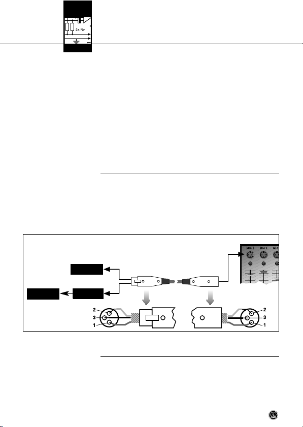
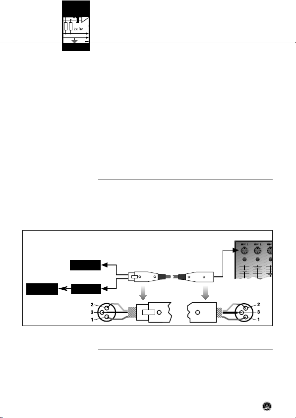
eine Stromversorgung. Das Mikrofon besitzt einen symmetrischen Ausgang mit 3-poligem XLR-Stecker:
Stift 1 = Masse
Stift 2 = Tonader (inphase)
Stift 3 = Tonader (return)
Sie können das Mikrofon an symmetrische Mikrofoneingänge
mit oder ohne Phantomspeisung anschließen. Die Phantomspeisegeräte von AKG erlauben Ihnen, das Mikrofon auch an
unsymmetrische Eingänge anzuschließen.
1. Schließen Sie das Mikrofon mit einem XLR-Mikrofonkabel
an einen symmetrischen XLR-Mikrofoneingang mit Phantomspeisung an.
2. Schalten Sie die Phantomspeisung ein. (Lesen Sie dazu in
der Betriebsanleitung des jeweiligen Gerätes nach.)
3.2
3.3
Abb. 1: Anschluss an symmetrischen Eingang
6
C 451 B
Page 7
3 Anschluss
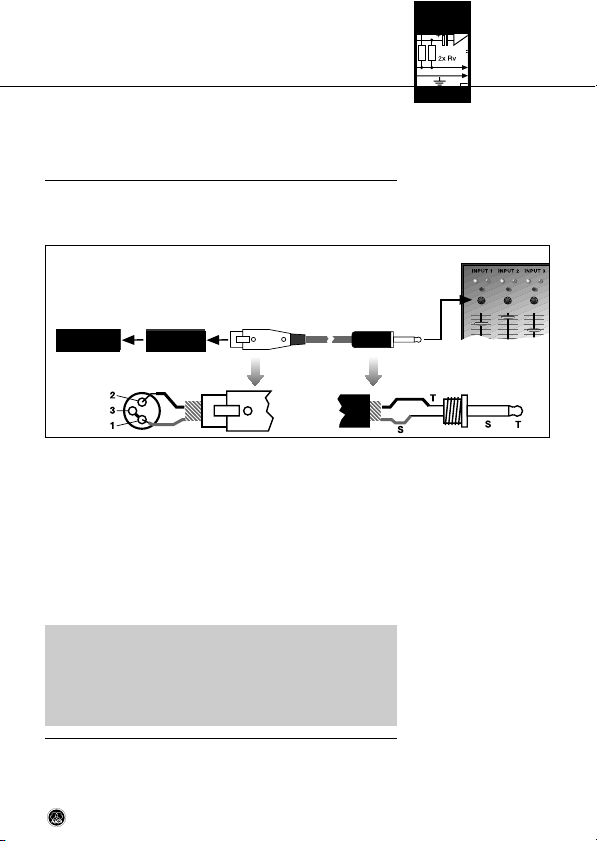
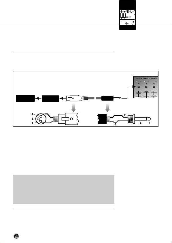
• Wenn Ihr Mischpult keine Phantomspeisung besitzt, schalten Sie zwischen Mikrofon und Mischpulteingang ein AKGPhantomspeisegerät B 18 (optional).
Das Phantomspeisegerät B 18 von AKG können Sie auch an einen unsymmetrischen Eingang anschließen.
C 451B
Abb. 2: Anschluss an unsymmetrischen Eingang
• Verwenden Sie dazu ein Kabel mit XLR-Stecker (weiblich)
und Mono-Klinkenstecker:
1. Verbinden Sie im XLR-Stecker mittels einer Drahtbrücke
Stift 1 mit Stift 3 und mit der Abschirmung.
2. Verbinden Sie die innere Ader des Kabels mit Stift 2 des
XLR-Steckers und der Spitze des Klinkensteckers.
• Beachten Sie, dass unsymmetrische Kabel Einstreuungen
aus Magnetfeldern (von Netz- und Lichtkabeln, Elektromotoren usw.) wie eine Antenne aufnehmen können. Bei Kabeln, die länger als 5 m sind, kann dies zu Brumm- und
ähnlichen Störgeräuschen führen.
B 18
3.3 Symmetrischer
Eingang ohne
Phantomspeisung
Siehe Abb. 1 (S. 6).
3.4 Unsymmetrischer
Eingang
Siehe Abb. 2.
Hinweis:
C 451 B
7
Page 8
4 Anwendung
4.1 Einleitung
4.2 Naheffekt
4.3 Rückkopplung bei
Beschallungsanlagen
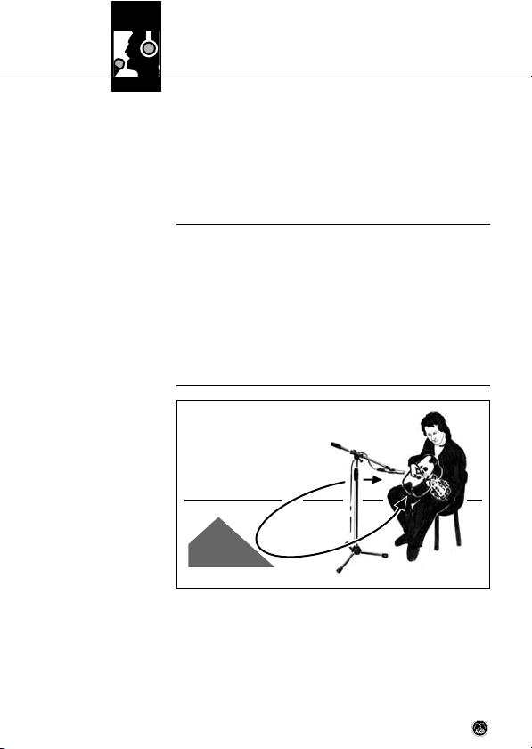
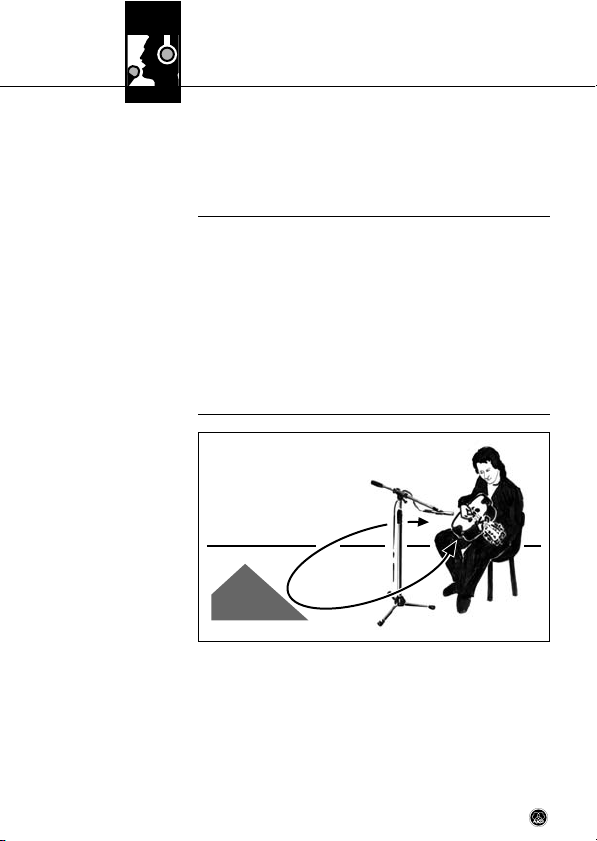
Abb. 3: Mikrofonaufstellung für minimale
Rückkopplung
Das stabförmige Gehäuse, die präzise Akustik, sowie die Vielzahl an passendem Zubehör von AKG erlauben eine vielseitige
und praxisgerechte Anwendung des Mikrofons an einem breiten Spektrum von Instrumenten.
• Beachten Sie bitte die folgenden Hinweise, um Ihr Mikrofon
optimal einsetzen zu können.
Mikrofone mit Richtwirkung haben bedingt durch das akustische Prinzip einen mehr oder weniger ausgeprägten Naheffekt.
Dieser bewirkt eine besonderen Betonung der tiefen Frequenzanteile, die mit abnehmendem Mikrofonabstand zur Schallquelle
zunimmt. Hörbar ist diese Betonung bereits ab etwa 60 cm. Je
nach Schallquelle kann dieser Effekt erwünscht oder auch unerwünscht sein und ist durch entsprechende Mikrofonplatzierung zu erreichen bzw. auszugleichen.
Die Rückkopplung kommt dadurch zustande, dass ein Teil des
von den Lautsprechern abgegebenen Schalls vom Mikrofon
aufgenommen und verstärkt wieder den Lautsprechern zugeleitet wird. Ab einer bestimmten Lautstärke (der Rückkopplungsgrenze) läuft dieses Signal gewissermaßen im Kreis, die
Anlage heult und pfeift und kann nur durch Zurückdrehen des
8
C 451 B
Page 9
4 Anwendung
Lautstärkereglers wieder unter Kontrolle gebracht werden. Um
dieser Gefahr zu begegnen, hat das Mikrofon eine nierenförmige Richtcharakteristik. Das bedeutet, dass es für Schall, der
von vorne (von der Schallquelle) einfällt am empfindlichsten ist,
während es auf seitlich einfallenden Schall oder Schall, der von
hinten auftrifft (z.B. von Monitorlautsprechern), kaum anspricht.
Minimale Rückkopplungsneigung erreichen Sie, indem Sie die
PA-Lautsprecher vor den Mikrofonen (am vorderen Bühnenrand) aufstellen. Wenn Sie Monitorlautsprecher verwenden, lassen Sie Ihr Mikrofon nie direkt auf die Monitore oder die PA-Lautsprecher zeigen. Rückkopplung kann auch durch Resonanzerscheinungen (als Folge der Raumakustik), besonders im unteren Frequenzbereich, ausgelöst werden, also indirekt durch den
Naheffekt. In diesem Fall brauchen Sie oft nur den Mikrofonabstand zu vergrößern, um die Rückkopplung zum Abreißen zu
bringen.
Siehe Abb. 3 auf Seite 8.
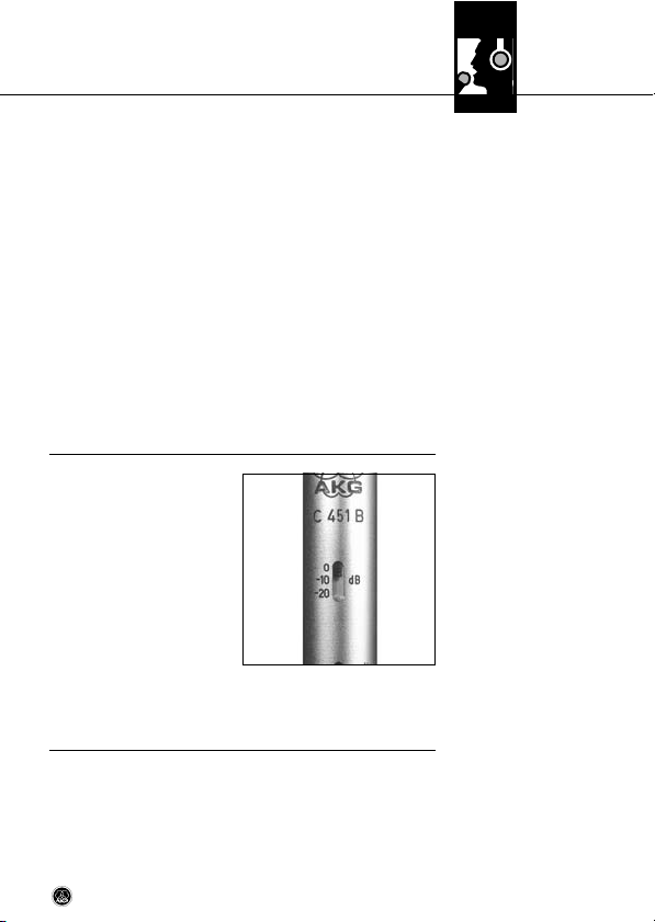
Bei besonders lauten Schallquellen bzw. besonders kleinen Aufnahmeabständen kann
der auf die Membran auftreffende Schalldruck erheblich
sein und das elektrische Ausgangssignal des Wandlers so
hoch werden lassen, dass die
nachfolgende Impedanwandler-/Verstärkerstufe übersteuert wird und so zu hörbaren Verzerrungen führt. Zur Vermeidung
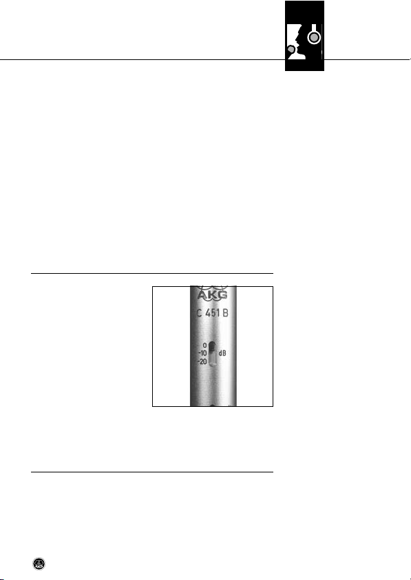
dieser Gefahr können Sie am Mikrofonschaft eine Vorabschwächung um 10 dB (ca. 1:3) bzw. 20 dB (ca. 1:10) einschalten.
C 451 B
4.4 Vorabschwächung
Abb. 4: Schalter für
Vorabschwächung
9
Page 10
4 Anwendung
Bassabschwächung
4.5
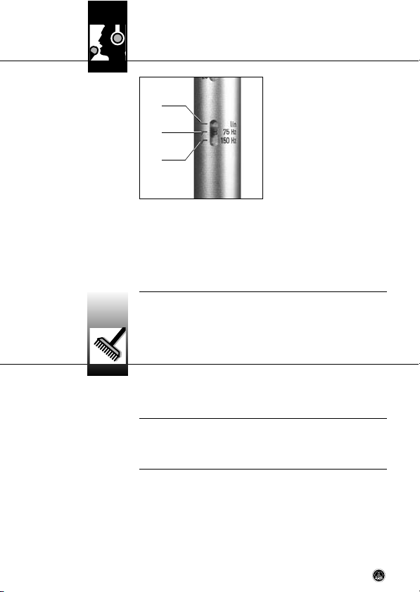
Abb. 5: Schalter für
Bassabschwächung
Siehe Abb. 5.
5.1 Gehäuseoberfläche
5.2 Windschutz
Tieffrequente Rumpel- oder
Windgeräusche von norma-
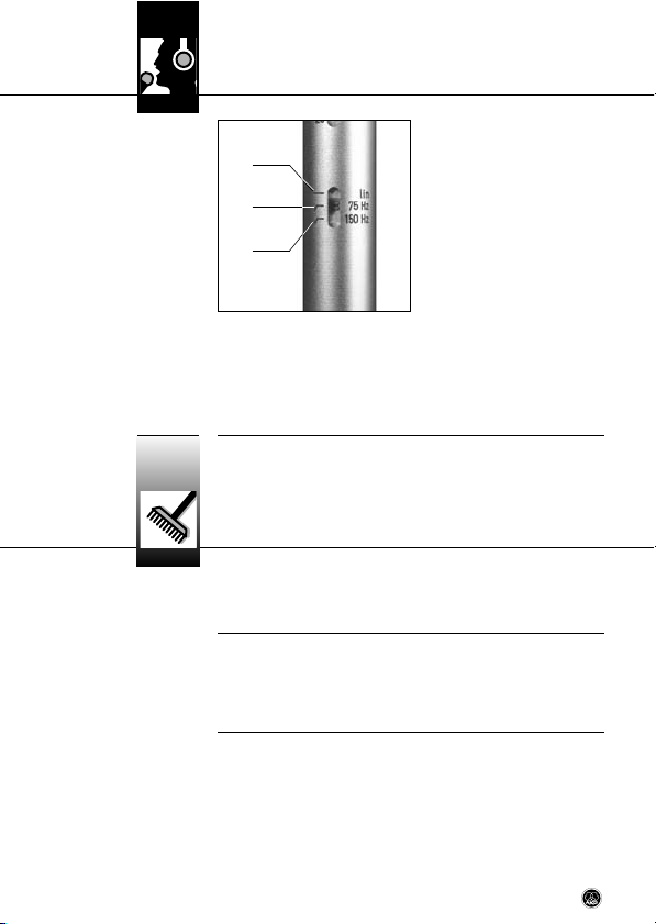
dieser Gefahr können Sie am Mikrofonschaft ein Tiefenfilter einschalten. Sie können das Filter je nach Stör- und Nutzsignalspektrum von der Linearstellung (1) auf die Grenzfrequenz von
75 Hz (2) oder 150 Hz (3) einstellen. Die Steilheit des Tiefenfilters beträgt in beiden Fällen 12 dB/Oktave (ca. 1:4) nach unten.
lerweise nicht als störend
wahrgenommenen Quellen
wie Klimaanlagen, Verkehrslärm, Gebäudegeräusche, etc.
kommen bei einer Aufnahme
sehr deutlich zum Vorschein
und können deshalb sehr störend wirken. Zur Vermeidung
5 Reinigung
• Reinigen Sie die Gehäuseoberfläche des Mikrofons mit einem mit Wasser befeuchteten Tuch.
• Waschen Sie den Schaumstoff-Windschutz mit Seifenwasser. Der Windschutz ist sofort nach dem Trocknen wieder
einsatzbereit.
10
C 451 B
Page 11
6 Technische Daten
Richtcharakteristik: Niere
Übertragungsbereich: 20 bis 20.000 Hz ± 1,5 dB von Sollkurve
Leerlauf-Übertragungsfaktor: 9 mV/Pa (- 41 dBV bez. auf 1 V/Pa)
Elektrische Impedanz: < 200 Ohm
Empfohlene Lastimpedanz: > 1000 Ohm
Grenzschalldruck für k = 0,5% : 112 Pa / 135 dB SPL (0 dB Abschwächung)
Äquivalentschalldruckpegel nach IEC 60268-4 (A-bewertet): 18 dB(A)
Dynamikbereich: 117 dB max. (A-bew.)*)
Vorabschwächung: schaltbar auf 0, - 10, - 20 dB
Bassabschwächung: schaltbar auf linear, 75 Hz, 150 Hz, 12 dB/Oktave
Speisespannung: 9 - 52 Volt Phantomspeisung nach IEC 61938
Betriebstemperatur: - 20°C bis + 60°C
Stecker: 3-pol. XLR-Stecker
Gehäuseoberfläche: seidenglanz-vernickelt
Abmessungen: 19 mm ø x 160 mm
Gewicht (netto/ brutto): 125 g / 760 g
*) Diese Werte gelten für 48-Volt Phantomspeisung und sind um 2 dB für 24-Volt, bzw. um 8 dB für
12-Volt Phantomspeisung zu reduzieren.
Dieses Produkt entspricht den in der Konformitätserklärung angegebenen Normen. Sie können die
Konformitätserklärung auf http://www.akg.com oder per E-Mail an sales@akg.com anfordern.
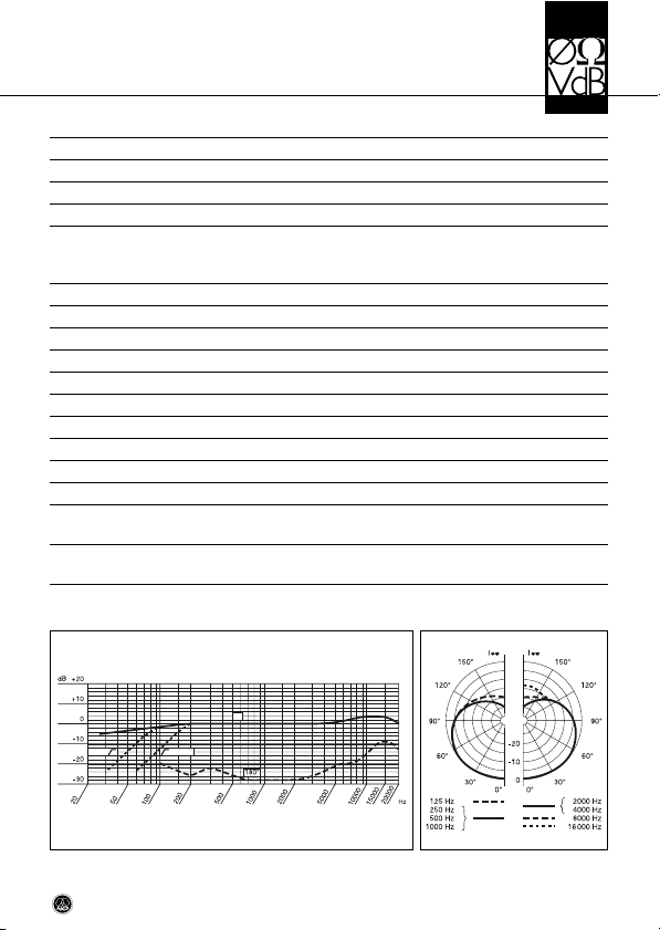
Frequenzgang Polardiagramm
0ϒ
150 Hz75 Hz
355 Pa / 145 dB SPL (10 dB Abschwächung)
1120 Pa / 155 dB SPL (20 dB Abscwächung)
C 451 B
11
Page 12
Table of Contents
Page
1 Safety and Environment.....................................................................13
1.1 Safety..........................................................................................13
1.2 Environment.................................................................................13
2 Description ........................................................................................14
2.1 Introduction..................................................................................14
2.2 Packing List .................................................................................14
2.3 Optional Accessories.....................................................................14
2.4 Selected Features .........................................................................14
2.5 Summary .....................................................................................15
3 Interfacing.........................................................................................16
3.1 General........................................................................................16
3.2 Balanced Input with Phantom Power ..............................................16
3.3 Balanced Input with No Phantom Power..........................................17
3.4 Unbalanced Input .........................................................................17
4 Using Your Microphone ......................................................................18
4.1 Introduction..................................................................................18
4.2 Proximity Effect ............................................................................18
4.3 Feedback in Live Sound Situations .................................................18
4.4 Preattenuation Pad .......................................................................19
4.5 Highpass Filter .............................................................................20
5 Cleaning ............................................................................................20
5.1 Microphone Body .........................................................................20
5.2 Windscreen..................................................................................20
6 Specifications....................................................................................21
12
C 451 B
Page 13

1 Safety and Environment
L
• Please make sure that the piece of equipment your
microphone will be connected to fulfills the safety
regulations in force in your country and is fitted with a
ground lead.
1. When scrapping the equipment, separate the case, circuit
boards, and cables, and dispose of all components in accordance with local waste disposal rules.
2. The packaging of the equipment is recyclabe. To dispose of
the packaging, make sure to use a collection/recycling system provided for that purpose and observe local legislation
relating to waste disposal and recycling.
1.1 Safety
!
L
1.2 Environment
C 451 B
13
Page 14
2 Description
2.1 Introduction
2.2 Packing List
2.3 Optional
Accessories
2.4 Selected Features
Thank you for purchasing an AKG product. Please take a few
minutes to read the instructions below carefully before op-
erating the equipment. Please keep the Manual for future reference. Have fun and impress your audience!
• 1 Soundtool Case (small)
• 1 C 451 B with individual re-
sponse curve
• 1 SA 60
• 1 W 90
• Check that the packaging contains all of the items listed
above. Should any of these items be missing, please contact your AKG dealer.
• For optional accessories, refer to the current AKG catalog or
folder, or visit www.akg.com. Your dealer will be glad to
help.
• Same transducer as in the legendary CK 1.
• Rugged construction.
• Low self-noise.
• Low current consumption.
• High reliability.
• Transformerless output stage.
• Operates on phantom power to IEC 61938.
• Built-in, switchable 10-dB or 20-dB pre attenuation pad.
• Built-in, switchable 12 dB/octave highpass filter at 75 Hz
or 150 Hz.
14
C 451 B
Page 15
2 Description
crophone, the C 451 EB + CK 1. The new C 451B, however,
uses a fixed capsule to eliminate the mechanical problems of
the original modular design. The microphone is the perfect
choice for any application where sounds, particularly their transient content, need to be captured with maximum accuracy.
Owing to its extremely light diaphragm, the microphone is
highly insensitive to handling noise. An all-metal body provides
efficient protection from RF interference and the microphone is
rugged enough to give excellent results even under very harsh
conditions.
A switchable 10-dB/20-dB preattenuation pad increases the
microphone's SPL capability when close-miking high-energy
sound sources or driv ing preamps or mixers with limited headroom.
A switchable highpass filter at 75 Hz or 150 Hz helps minimize
low-end distortion that may be caused, e.g., by rumble or wind
noise. The slope of the filter is approx. 12 dB/octave and its corner frequency (3 dB down point) is selectable at 75 Hz or 150 Hz.
2.5 SummaryThe C 451B is an updated rerun of a classic AKG condenser mi-
C 451 B
15
Page 16
3 Interfacing
3.1 General
Refer to sections
3.2 and 3.3.
3.2 Balanced Input
with Phantom Power
Refer to fig. 1 below.
C 451B
C 451B
B 18
The C 451B is a condenser microphone and therefore needs a
power supply.
The microphone provides a balanced output on a 3-pin male
XLR connector:
Pin 1: ground
Pin 2: hot
Pin 3: return
• You can connect the microphone to balanced microphone
inputs with or without phantom power. AKG phantom power
supplies allow you to connect the microphone to unbalanced inputs as well.
1. Use an XLR cable to connect the microphone to a balanced
XLR input with phantom power.
2. Switch the phantom power on. (Refer to the instruction
manual of the unit to which you connected your C 451B.)
3.2
3.3
Fig. 1: Connecting to a balanced input.
16
C 451 B
Page 17
3 Interfacing
1. If your mixer provides no phantom power, connect an optional AKG B 18 phantom power supply between the microphone and the mixer.
You may connect the AKG B 18 phantom power supply to
unbalanced inputs as well.
C 451B
Fig. 2: Connecting to an unbalanced input.
• Use a cable with a female XLR connector and TS jack plug:
1. On the XLR connector, use a wire bridge to connect pin 1 to
pin 3 and the cable shield.
2. Connect the inside wire of the cable to pin 2 on the XLR
connector and the tip contact of the jack plug.
• Unbalanced cables may pick up interference from stray
magnetic fields near power or lighting cables, electric motors, etc. like an antenna. This may introduce hum or similar noise when you use a cable that is longer than 16 feet
(5 m).
B 18
3.3 Balanced Input
with No Phantom
Power
Refer to fig. 1 (p. 16).
3.4 Unbalanced Input
Refer to fig. 2 above.
Note:
C 451 B
17
Page 18
4 Using Your Microphone
4.1 Introduction
4.2 Proximity Effect
4.3 Feedback in Live
Sound Situations
Fig. 3: Microphone
placement for max imum
gain before feedback.
The rod-shaped body, accurate response, and many matching
accessories from AKG make it easy to use the microphone to
pick up a wide range of different instruments.
• Read the hints below to get the best possible results.
Owing to their acoustic principle, unidirectional microphones
exhibit what is called "proximity effect". This means that the lowfrequency content of a sound signal will be progressively boosted as you move the microphone closer to the sound source.
Proximity effect begins to become audible at a working distance
of about 2 feet (60 cm). Depending on the nature of the sound
source, proximity effect may be desirable or a nuisance.
Place the microphone closer to the sound source to accentuate,
or further away to reduce proximity effect.
Feedback results from part of the sound projected by a speaker
being picked up by a microphone, fed to the amplifier, and projected again by the speaker. Above a specific volume or “system
gain” setting called the feedback threshold, the signal starts being regenerated indefinitely, making the sound system howl and
the sound engineer desperately dive for the master fader to reduce the volume and stop the howl ing.
18
C 451 B
Page 19
4 Using Your Microphone
To increase usable gain before feedback, the microphone has a
cardioid polar pattern. This means that the microphone is most
sensitive to sounds arriving from in front of it (from the sound
source) while picking up much less of sounds arriving from the
sides or rear (from monitor speakers for instance).
To obtain maximum gain before feedback, place the main
(“FOH”) speakers in front of the micro phones (along the front
edge of the stage). If you use monitor speakers, be sure never to
point any microphone directly at the monitors, or at the FOH
speakers.
Feedback may also be triggered by resonances depending on
the acoustics of the room or hall. With resonances at low frequencies, proximity effect may cause feedback. In this case, it is
often enough to move away from the microphone a little to stop
the feedback.
Refer to fig. 3 on
page 18.
If you are miking up an extremely loud sound source or
have placed the microphone
ex tremely close to an instrument, the diaphragm may be
ex posed to extremely high
sound pressure levels. As a
result, the electrical output
signal of the transducer may
become high enough to overload the subsequent impedance converter/preamplifier and introduce audible distortion. To minimize the risk of getting audible distortion, use the preattenuation switch on the microphone
shaft to switch in 10 dB (1:3) or 20 dB (1:10) of preattenuation.
C 451 B
4.4 Preattenuation
Pad
Fig. 4: Preattenuation
switch.
19
Page 20

4 Using Your Microphone
4.5 Highpass Filter
Fig. 5: Highpass filter
switch.
Refer to fig. 5 above.
5.1 Microphone Body
5.2 Windscreen
Low-frequency rumble or
wind noise such as air condi-
the spectra of the wanted and unwanted signals, set the highpass filter switch on the microphone shaft from flat (1) to a corner frequency of 75 Hz (2) or 150 Hz (3). In either position, the
slope of the filter is 12 dB/octave (1:4) downward.
tioning rumble, traffic noise,
structure-borne noise, etc.
that usually pass unnoticed
may become a clearly audible
nuisance on a recording.
To minimize low- frequency
noise, you can switch in the
highpass filter. Depending on
5 Cleaning
• Use a soft cloth moistened with water to clean the surface
of the microphone body .
• Wash the foam windscreen in soap suds. Do not use the
windscreen before it has dried completely.
20
C 451 B
Page 21

Specifications
Polar pattern: cardioid
Frequency range: 20 to 20,000 Hz ± 1.5 dB from published curve
Sensitivity: 9 mV/Pa / -41 dBV re 1 V/Pa
Electrical impedance: < 200 ohms
Recommended load impedance: > 1000 ohms
Max. SPL for 0.5% THD: 112 Pa / 135 dB SPL with 0 dB preattenuation*)
Equivalent noise level to IEC 60268-4 (A-weighted): 18 dB-A
Dynamic range: 117 dB max. (A-weighted)*)
Preattenuation pad: switchable to 0 dB, -10 dB, -20 dB
Highpass filter: switchable to flat or 12 dB/octave at 75 Hz or 150 Hz
Powering: 9 to 52 V phantom power to IEC 61938
Operating temperature: -20°C to +60°C
Connector: 3-pin male XLR
Finish: satin nickel plated
Size: dia.: 19 mm (0.7 in.); length: 160 mm (6.3 in.)
Net/shipping weight: 125 g (4.4 oz.) / 760 g (1.7 lbs.)
*) Values measured with 48-V phantom power. Reduce by 2 dB for 24-V or 8 dB for 12-V phantom
power.
This product conforms to the standards listed in the Declaration of Conformity. To order a free copy of
the Declaration of Conformity, visit http://www.akg.com or contact sales@akg.com.
Frequency Response Polar Diagram
0ϒ
150 Hz75 Hz
355 Pa / 145 dB SPL with 10 dB preattenuation*)
1120 Pa / 155 dB SPL with 20 dB preattenuation*)
C 451 B
21
Page 22

Sommaire
Page
1 Sécurité et écologie...........................................................................23
1.1 Sécurité .......................................................................................23
1.2 Ecologie.......................................................................................23
2 Description ........................................................................................24
2.1 Introduction..................................................................................24
2.2 Fournitures ..................................................................................24
2.3 Accessoires optionnels .................................................................24
2.4 Caractéristiques particulières ........................................................24
2.5 Description succincte....................................................................25
3 Raccordement ...................................................................................26
3.1 Indications générales ....................................................................26
3.2 Entrée symétrique avec alimentation fantôme .................................26
3.3 Entrée symétrique sans alimentation fantôme .................................27
3.4 Entrée asymétrique .......................................................................27
4 Utilisation ..........................................................................................28
4.1 Introduction..................................................................................28
4.2 Efffet de proximité.........................................................................28
4.3 Réaction acoustique dans les systèmes de sonorisation ...................28
4.4 Préattenuation..............................................................................29
4.5 Filtre coupe-bas ...........................................................................30
5 Nettoyage..........................................................................................30
5.1 Surface du boîtier .........................................................................30
5.2 Bonnette anti-vent ........................................................................30
6 Caractéristiques techniques..............................................................31
22
C 451 B
Page 23

1 Sécurité et écologie
L
• Vérifiez si l’appareil sur lequel vous voulez brancher
le microphone répond aux règlements de sécurité en
vigueur et possède une prise de terre de sécurité.
1. Si vous mettez le micro à la ferraille, démontez boîtier,
électronique et câbles et éliminez chacun de ces éléments
conformément aux prescriptions en vigueur.
2. L'emballage est recyclable. Déposez l'emballage dans un
récipient de collecte prévu à cet effet.
1.1 Sécurité
!
L
1.2 Ecologie
C 451 B
23
Page 24

2 Description
2.1 Introduction
2.2 Fournitures
2.3 Accessoires
optionnels
2.4 Caractéristiques
particulières
Nous vous remercions d’avoir choisi un produit d’AKG et vous
invitons à lire attentivement le présent mode d’emploi
avant de mettre votre micro en service. Conservez soigneusement le mode d’emploi pour l’avoir toujours sous la main
lorsque vous avez besoin de le consulter. Nous espérons que
vous aurez beaucoup de satisfaction et de succès avec votre
micro.
• 1 Soundtool Case (petit)
• 1 C 451B avec courvbe de ré-
ponse en fréquence individuelle
• 1 SA 60
• 1 W 90
• Assurez-vous que l’emballage contient bien toutes les pièces indiquées ci-dessus. Si ce n’est pas le cas, contactez
immédiatement votre fournisseur AKG.
• Vous trouverez la liste des accessoires optionnels dans le
catalogue/dépliant AKG actuel ou sur www.akg.com. Votre
fournisseur se tient à votre disposition pour vous conseiller.
• Système acoustique de la légendaire CK 1
• Eléments mécaniques robustes
• Bruit propre minime
• Très faible consommation
• Extrême sécurité de fonctionnement
• Etage sortie sans transfornateur
• Accepte toute alimentation fantôme selon IEC 61938
24
C 451 B
Page 25

2 Description
• Préatténuation de 10 dB ou 20 dB incorporée, commutable
• Fitre coupe-bas incorporé, commutable, intervenant à
75 Hz ou 150 Hz (12 dB/octave)
Le C 451B est la version moderne du légendaire microphone
électrostatique AKG C 451EB + CK 1. On a renoncé cette fois à
la conception modulaire pour éviter les inconvénients mécaniques incontestables d’une telle construction. Le
C 451B s’adresse principalement à toutes les applications dans
lesquelles il importe de restituer les événements sonores, et
plus particulièrement les éléments transitoires d’un signal, avec
une extrême précision.
Grâce à sa membrane légère, le micro est extrêmement peu
sensible aux bruits de manipulation. Son boîtier entièrement
métallique assure une remarquable protection contre les parasites HF tandis que sa construction éprouvée permet de l’utiliser
sans problème dans les conditions les plus diverses.
La préatténuation de 10 dB ou 20 dB commutable représente
un avantage particulièrement appréciable dans le cas d’une
pression acoustique élevée (p.ex. lorsqu’on utilise le micro à
proximité de sources sonores très puissantes) ou lorsque l’étage d’entrée de l’amplificateur ou de la table de mixage présente un niveau d’entrée maximum limité ; on évite en effet
ainsi que la saturation de l’étage d’entrée intervienne avant que
l’on n’ait pu utiliser la puissance limite du micro.
Le filtre coupe-bas commutable permet en outre de supprimer
les distorsions à très basse fréquence qui peuvent se produire
p.ex. par suite de rumble ou de bruits de vent. La pente du filtre
est de 12 dB/octave, la fréquence de coupure (point de -3 dB)
étant sélectionnable à 75 Hz ou 150 Hz.
2.5 Description
succincte
C 451 B
25
Page 26

3 Raccordement
3.1 Indications
générales
Voir points 3.2 et 3.3
3.2 Entrée symétrique
avec alimentation
fantôme
Voir Fig. 1.
C 451B
C 451B
B 18
Le C 451B est un microphone électrostatique ; il a donc besoin
d’une alimentation.
Le microphone possède une sortie symétrique avec fiche XLR
tripolaire :
broche 1 = masse
broche 2 = point chaud
broche 3 = point froid
Le micro peut être raccordé à des entrées micro symétriques
avec ou sans alimentation fantôme. Les alimentations fantômes
AKG permettent également de le raccorder à des entrées asymétriques.
1. Connectez le microphone à l’aide d’un câble de micro XLRXLR sur une entrée de micro symétrique type XLR avec alimentation fantôme.
2. Mettez l’alimentation fantôme sous tension (Veuillez vous
reporter à la notice de l’équipement utilisé).
3.2
3.3
Fig. 1 : connexion sur une entrée symétrique
26
C 451 B
Page 27

3 Raccordement
• Si votre table de mixage ne possède pas d’alimentation fantôme, insérez une alimentation fantôme AKG optionnelle
B 18 entre le micro et l’entrée de la table de mixage.
Vous pouvez aussi connecter l’alimentation fantôme B 18 d’AKG
sur une entrée asymétrique.
C 451B
Fig. 2 : Connexion sur une entrée asymétrique
• Il vous faut un câble avec une fiche XLR femelle et une fiche
à jack mono:
1. Pontez les contacts 1 et 3 de la fiche XLR et reliez-les au
blindage du câble.
2. Reliez le conducteur interne du câble au contact 2 de la fiche XLR et à la pointe de la fiche à jack.
• Les câbles asymétriques peuvent capter comme une antenne les interférences de champs magnétiques (câbles
lumière ou force, moteurs électriques, etc.). Si le câble
mesure plus de 5 m ce phénomène pourra se traduire par
des ronflements et autres parasites.
B 18
3.3 Entrée symétrique
sans alimentation
fantôme
Voir Fig. 1 (page 26)
3.4 Entrée
asymétrique
Voir Fig. 2.
Remarque :
C 451 B
27
Page 28

4 Utilisation
4.1 Introduction
4.2 Effet de proximité
4.3 Réaction
acoustique
dans les systèmes
de sonorisation
Fig. 3: Positionnement
du micro pour minimiser
le risque de Larsen
Son boîtier en forme de tube, la précision de son système
acoustique ainsi que les nombreux accessoires AKG avec lesquels il peut être utilisé font du C 451B un micro véritablement
orienté sur l’application réelle, offrant les possibilités d’utilisation les plus variées pour une multitude d’instruments.
• Vous pourrez obtenir un résultat optimal en vous conformant aux instructions ci-dessous.
Leur principe acoustique fait que les microphones directionnels
ont un effet de proximité plus ou moins marqué. Il en résulte une
certaine accentuation des fréquences basses augmentant au
fur et à mesure que le micro se rapproche de la source sonore.
Cette accentuation est audible en gros à partir de 60 cm. Cet effet peut être souhaitable ou non, suivant la source sonore ; on
peut l’obtenir ou l’éliminer en choisissant l’emplacement du
micro en conséquence.
L’effet Larsen prend naissance quand une partie du son émis
par les haut-parleurs est captée par le microphone, est amplifiée, puis est projetée à nouveau par les haut-parleurs. La réaction acoustique se développe à partir d’un certain niveau (seuil
d’accrochage) qui correspond à une sorte de bouclage du cir-
28
C 451 B
Page 29

4 Utilisation
cuit. Le système se met alors à siffler. Pour l’interrompre, il faut
ré duire le volume.
Pour éviter les réactions acoustiques, le microphone a une
courbe de réponse polaire du type cardioïde. Cela veut dire qu’il
est très sensible aux sons venant de l’avant (de la source sonore), peu sensible à ceux venant des côtes et pratiquement
pas à tout ceux qu’il reçoit de l’arrière.
En plaçant les haut-parleurs de chant devant les microphones,
donc sur le bord latéral de la scène on obtient la meilleure protection contre l’effet de Larsen. Lorsque vous utilisez des retours de scène, ne dirigez jamais votre micro directement sur
les retours ou les haut-parleurs de la sono.
Certains phénomènes de résonance (tels qu’ils sont déterminés
par l’acoustique d’une salle) peuvent également provoquer un
Larsen, et cela surtout dans la partie inférieure du spectre sonore; c’ést donc – indirectement – l’effet de proximité qui en est
responsable. Dans ce cas il suffit souvent d’augmenter la distance du microphone pour faire disparaître le Larsen.
Voir Fig. 3 (page 28).
Dans le cas de sources sonores particulièrement puissantes ou lorsque le micro se
trouve très près de la source,
la pression acoustique s’exerçant sur la membrane peut
être considérable et le signal
électrique de sortie du transducteur assez fort pour provoquer la saturation de l’étage
adaptateur d’impédance/amplifi cateur qui lui fait suite, ce qui
se traduit par des distorsions audibles. Vous pourrez éviter cet
inconvénient en utilisant la préatténuation commutable sur 10 dB
(env. 1 : 3) ou 20 dB (env. 1 : 10).
C 451 B
4.4 Préatténuation
Fig. 4 : Commutateur de
préatténuation
29
Page 30

4 Utilisation
4.5 Filtre coupe-bas
Fig. 5 : Commutateur du
filtre coupe-bas
Voir Fig. 5.
5.1 Surface du boîtier
5.2 Bonnette
anti-vent
Les bruits de vent et le rumble
à basses fréquences prove-
ment désagréables.
Vous pouvez remédier à cet inconvénient en mettant en service
le filtre coupe-bas à l’aide d’un bouton se trouvant sur le corps
du micro. Suivant le spectre des signaux bruits ambiants/signaux utiles, vous pouvez rester en position linéaire (1) ou sélectionner une fréquence de coupure de 75 Hz (2) ou 150 Hz (3).
La pente du filtre est dans les deux cas de 12 dB /octave (env. 1 : 4)
vers le bas.
nant de sources qui ne sont
normalement pas ressenties
comme gênantes, telles que
climatisations, bruits de la circulation, bruits dans les immeubles, etc. sont nettement
audibles à l’enregistrement et
risquent d’être particulière-
5 Nettoyage
• Nettoyez la surface extérieure du boîtier du micro avec un
chiffon légèrement humide (eau claire).
• Lavez la bonnette anti-vent en mousse à l'eau savonneuse.
Une fois sèche, la bonnette anti-vent peut être immédiatement réutilisée.
30
C 451 B
Page 31

6 Caractéristiques techniques
Directivité : cardioïde
Réponse en fréquence : 20 – 20.000 Hz ± 1,5 dB de la courbe nominale
Sensibilité : 9 mV/Pa (-41 dBV rapp. à 1V/Pa)
Impédance électrique : ≤ 200 OHMS
Impédance de charge recommandée : ≥1000 OHMS
Niveau maximum de pression acoustique 112 Pa / 135 dB SPL avec une atténuation de 0 dB*)
pour un facteur de distorsion de 0,5% : 355 Pa / 145 dB SPL avec une atténuation de 10 dB*)
Niveau de bruit équivalent mesuré selon CEI 60268-4 (pondéré A): 18 dB (A)
Dynamique : maxi. 117 dB (pondérée A) *)
Préatténuation : réglable sur 0, -10, -20 dB
Atténuation des graves : réglable sur linéaire, 75 Hz, 150 Hz, 12 dB/octave
Tension d’alimentation: Alimentation fantôme de 9 … 52 V selon CEI 61938
Température de service : -20°C à +60°C
Connecteur : type XLR, 3 points
Boîtier : finition nickelée satinée
Dimensions : Ø 19 mm x 160 mm
Poids net / brut : 125 g / 760 g
*) Ces chiffres correspondent à une alimentation fantôme de 48 volts ; ils se réduisent de 2 dB pour
24 volts et 8 dB pour 12 volts.
Ce produit est conforme aux normes citées dans la Déclaration de Conformité, dont vous pouvez
prendre connaissance en consultant le site http://www.akg.com ou en adressant un e-mail à
sales@akg.com.
Courbe de fréquences Diagramme polaire
0ϒ
150 Hz75 Hz
1120 Pa / 155 dB SPL avec une atténuation de 20dB*)
C 451 B
31
Page 32

Indice
Pagina
1 Sicurezza ed ambiente ......................................................................33
1.1 Sicurezza .....................................................................................33
1.2 Ambiente .....................................................................................33
2 Descrizione........................................................................................34
2.1 Introduzione .................................................................................34
2.2 In dotazione .................................................................................34
2.3 Accessori opzionali .......................................................................34
2.4 Caratteristiche particolari ..............................................................34
2.5 Breve descrizione .........................................................................35
3 Collegamento ....................................................................................36
3.1 Indicazioni generali .......................................................................36
3.2 Ingresso simmetrico con alimentazione phantom.............................36
3.3 Ingresso simmetrico senza alimentazione phantom .........................37
3.4 Ingresso asimmetrico....................................................................37
4 Impiego .............................................................................................38
4.1 Introduzione .................................................................................38
4.2 Effetto di prossimità ......................................................................38
4.3 Reazione nei sistemi di sonorizzazione ............................................38
4.4 Preattenuazione ...........................................................................39
4.5 Attenuazione dei bassi ..................................................................40
5 Pulizia................................................................................................40
5.1 Superficie del corpo ......................................................................40
5.2 Antisoffio .....................................................................................40
6 Dati tecnici ........................................................................................41
32
C 451 B
Page 33

1 Sicurezza ed ambiente
L
• Controllate, per favore, se l’apparecchio al quale volete collegare il microfono, corrisponde alle norme di
sicurezza vigenti e se è dotato di una messa a terra di
sicurezza.
1. Se rottamate l’apparecchio, separate scatola, parti elettroniche e cavi e smaltite tutti i componenti secondo le norme
di smaltimento vigenti al riguardo.
2. L'imballaggio è riciclabile. Smaltite l'imballaggio in un apposito sistema di raccolta.
1.1 Sicurezza
!
L
1.2 Ambiente
C 451 B
33
Page 34

2 Descrizione
2.1 Introduzione
2.2 In dotazione
2.3 Accessori
opzionali
2.4 Caratteristiche
particolari
Vi ringraziamo di aver scelto un prodotto della AKG. Leggete,
per favore, attentamente le istruzioni per l’uso, prima di
mettere in esercizio l’apparecchio, e conservate bene le
istruzioni per l’uso per poterle consultare in qualsiasi momento.
Vi auguriamo buon divertimento e buon successo!
• 1 Soundtool Case (piccolo)
• 1 C 451 B con curva di risposta
in frequenza individuale
• 1 SA 60
• 1 W 90
• Controllate per favore se la confezione contiene tutti i componenti di cui sopra. Se manca qualcosa rivolgetevi al vostro rivenditore AKG.
• Accessori opzionali si trovano nel catalogo/folder attuale
dell'AKG o al sito www.akg.com. Il vostro rivenditore è a vostra disposizione per eventuali consigli.
• Caratteristiche acustiche della leggendaria CK 1
• Meccanica robusta
• Pochissimi rumori di fondo
• Ridotto consumo di corrente
• Alta sicurezza d’esercizio
• Stadio d’uscita senza trasformatore
• Alimentazione tramite qualsiasi apparecchio di alimentazione phantom secondo IEC 61938
• Preattenuazione integrata, regolabile di 10 dB oppure di
20 dB
34
C 451 B
Page 35

2 Descrizione
• Filtro dei bassi integrato, regolabile; punto d’inserzione del
filtro a 75 Hz oppure a 150 Hz (12 db/ottava)
Il C 451B è la versione moderna del già storico microfono a condensatore C 451EB + CK 1 dell’AKG. La costruzione però non è
modulare, per poter evitare gli evidenti svantaggi meccanici
causati allora da questo tipo di costruzione. Può venir impiegato
soprattutto in quelle applicazioni in cui è importante trasmettere
eventi sonori in modo molto preciso, in particolare le parti transienti dei segnali.
Grazie alla sua membrana leggera, il microfono è largamente
insensibile contro i rumori prodotti dalle mani. Altre caratteristiche sono il corpo interamente in metallo e quindi poco sensibile
ai disturbi RF nonché l’esercizio senza problemi in quasi tutte le
situazioni dovuto all’affidabile costruzione.
La preattenuazione regolabile di 10 dB oppure di 20 dB è di particolare vantaggio quando si verificano forti pressioni sonore
(p.e. quando il microfono viene usato nelle vicinanze di fonti sonore ricche di energia) o quando si usano stadi d’ingressi di amplificatori o mixer con un livello d’ingresso massimo limitato,
perché senza la preattenuazione questi stadi collegati verrebbero sovraccaricati senza poter utilizzare in pieno la capacità di
modulazione del microfono.
L’attenuazione dei bassi regolabile sul microfono aiuta inoltre a
ridurre le distorsioni prodotte dalle frequenze molto basse che
possono verificarsi p.e. a causa di rumori causati dal tocco delle
mani o dal vento. La transconduttanza del filtro è di circa
12 db/ottava; la frequenza limite (punto -3 dB) sta – a scelta – a
75 Hz oppure a 150 Hz.
2.5 Breve descrizione
C 451 B
35
Page 36

3 Collegamento
3.1 Indicazioni
Vedi capitoli 3.2 e 3.3.
C 451B
generali
3.2. Ingresso
simmetrico con
alimentazione
phantom
Vedi fig. 1.
C 451B
B 18
Il C 451B è un microfono a condensatore e ha quindi bisogno di
alimentazione.
Il microfono è dotato di un’uscita simmetrica con connettore
XLR a 3 poli.
Pin 1 = massa
Pin 2 = filo audio (inphase)
Pin 3 = filo audio
Potete collegare il microfono ad ingressi microfonici simmetrici
con o senza alimentazione phantom. Gli alimentatori phantom
della AKG vi permettono anche di collegare il microfono ad ingressi asimmetrici.
1. Collegate il microfono ad un ingresso microfonico XLR simmetrico con alimentazione phantom servendovi di un cavo
microfonico XLR.
2. Inserite l’alimentazione phantom. (Leggete in merito le
istruzioni per l’uso del rispettivo apparecchio.)
3.2
3.3
Fig. 1:Collegamento ad un ingresso simmetrico
36
C 451 B
Page 37

3 Collegamento
• Se il vostro mixer non è dotato di alimentazione phantom,
interponete tra microfono e ingresso sul mixer un alimentatore phantom AKG B 18 opzionale.
L’alimentatori phantom B 18 dell’AKG può venir collegato anche
ad un ingresso asimmetrico.
C 451B
Fig. 2: Collegamento ad un ingresso asimmetrico
• Usate un cavo con una presa XLR e una spina jack mono:
1. Nella presa XLR, collegate con un ponte a filo i contatti 1 e 3
e portateli sullo schermo del cavo.
2. Collegate il conduttore interno del cavo con il contatto 2
della presa XLR e la punta della spina jack.
• Tenete presente che i cavi asimmetrici possono assorbire,
come un’antenna, irradiazioni da campi magnetici (cavi di
rete, cavi della luce, elettromotori ecc.). Nel caso di cavi la
cui lunghezza supera i 5 m, questo fenomeno può causare
ronzìi ed altri rumori disturbanti.
B 18
3.3 Ingresso simmetrico senza alimentazione phantom
Vedi fig. 1 (p 36).
3.4 Ingresso
asimmetrico
Vedi fig. 2.
Nota:
C 451 B
37
Page 38

4 Impiego
4.1 Introduzione
4.2 Effetto
di prossimità
4.3 Reazione
nei sistemi
di sonorizzazione
Fig. 3: Posizionamento
del microfono per
minimizzare il rischio
di reazione
Il corpo a forma di asta, l’acustica precisa e i numerosi accessori dell’AKG rendono questo microfono molto versatile e pratico nell’uso per una vasta gamma di strumenti.
• Tenete presenti le seguenti istruzioni per poter impiegare il
microfono in modo ottimale.
I microfoni direzionali hanno un effetto di prossimità più o meno
pronunciato, dovuto al principio acustico. Questo effetto produce una speciale enfatizzazione delle basse frequenze che aumenta quando diminuisce la distanza del microfono dalla fonte
sonora. Questa enfatizzazione si sente già a partire da una distanza di 60 cm circa. A seconda della fonte sonora, questo effetto può essere desiderato o indesiderato; può venir raggiunto
o compensato piazzando il microfono in modo idoneo.
La reazione è determinata dal fatto che il suono emesso dall’amplificatore viene in parte ripreso dal microfono che lo reinvia, amplificato, all’altoparlante. A partire da un determinato volume (“limite di reazione“) questo segnale dà luogo, in un certo
qual modo, ad un circolo vizioso, per cui il fischio emesso dall’impianto si intensifica sempre più e può venir arrestato solo diminuendo il volume.
38
C 451 B
Page 39

4 Impiego
Al fine di prevenire questo rischio, il microfono del microfono
dispone di una caratteristica direzionale cardioide. Vale a dire
che esso è particolarmente sensibile al suono che investe il microfono da davanti (dalla fonte sonora), mentre quasi non registra il suono che proviene dai lati o da dietro
(p. es. dagli altoparlanti monitor).
La massima sicurezza antireazione si ottiene posizionando le
casse PA davanti ai microfoni, vale a dire lateralmente sul margine anteriore del palco. Se usate altoparlanti monitor, non puntate il vostro microfono mai direttamente sui monitor o sugli altoparlanti dell’impianto di sonorizzazione.
La reazione può essere causata anche da risonanze (determinate dall’acustica dell’ambiente), in particolare nella gamma di
frequenze bassa, indirettamente quindi dall’effetto di prossimità. In questi casi spesso è sufficiente aumentare la distanza
dall microfono per inter rompere la reazione.
Vedi fig. 3 (p. 38).
In caso di fonti sonore particolarmente forti, oppure in caso
di distanze di registrazione
particolarmente ridotte, la
pressione sonora sulla membrana può essere notevole; il
segnale d’uscita elettrico del
trasduttore può diventare talmente forte che il successivo
stadio di trasformazione dell’impedenza / dello stadio di amplificazione viene sovraccaricato producendo distorsioni ben percettibili. Per evitare questo
pericolo potete inserire sul gambo del microfono la preattenuazione di 10 dB (1:3 circa) oppure di 20 dB (1:10 circa).
C 451 B
4.4 Preattenuazione
Fig. 4: Interruttore per la
preattenuazione
39
Page 40
4 Impiego
4.5 Attenuazione
dei bassi
Fig. 5: Interruttore per
l’attenuazione dei bassi
Vedi fig. 5.
5.1 Superficie
del corpo
5.2 Antisoffio
I rumori a basse frequenze
provenienti da fonti normal-
potete inserire sul gambo del microfono un filtro dei bassi. A seconda dello spettro dei segnali disturbanti e dei segnali utili potete portare il filtro dalla posizione lineare (1) alla posizione limite di 75 Hz (2) oppure di 150 Hz (3). La transconduttanza del
filtro dei bassi è in ambedue i casi di 12 dB/ottava (1:4 circa)
verso il basso.
mente non percepite come
disturbi, p.e. da impianti di
condizionamento dell’aria, dal
rumore del traffico ecc. vengono resi più manifesti dalle
registrazioni e percepiti quindi
come disturbanti.
Per evitare questo pericolo,
5 Pulizia
• Pulite la superficie della scatola del microfono con un
panno inumidito con acqua.
• Lavate l’antisoffio in espanso con acqua e sapone. Dopo
l’asciugamento l’antisoffio può venir usato subito.
40
C 451 B
Page 41

6 Dati tecnici
Direttività: cardioide
Risposta in frequenza: 20 – 20.000 Hz ± 1,5 dB dalla curva nominale
Sensibilità: 9 mV/Pa / -41 dBV rif. a 1V/Pa
Impedenza elettrica: <200 ohm
Impedenza di carico raccomandata: >1000 ohm
Pressione acustica limite 112 Pa / 135 dB SPL con attenuazione di 0 dB *)
per un fattore di distorsione di 0,5%: 355 Pa / 145 dB SPL con attenuazione di 10 dB *)
Pressione acustica equivalente secondo IEC 60268-4 (pond. A): 18 dB-A
Campo dinamico: 117 dB mass. (pond. A) *)
Preattenuazione: regolabile su 0, -10, -20 dB
Attenuazione dei bassi: 12 dB/ottava,regolabile su lineare, 75 Hz o 150 Hz
Tensione di alimentazione: 9 – 52 Volt alimentazione phantom secondo IEC 61938
Temperatura d’esercizio: da -20°C a +60°C
Connettore: connettore XLR a tre poli
Superficie corpo: lucentezza serica, nichelata
Dimensioni: diametro 19 mm x 160 mm
Peso (netto/lordo): 125 g / 760 g
*) Questi valori valgono per l’alimentazione phantom da 48 Volt e devono venir ridotti di 2 dB per
24 Volt, rispettivamente di 8 dB per 12 Volt.
Questo prodotto corrisponde alle norme elencate nella dichiarazione di conformità, che è disponibile al
sito http://www.akg.com oppure all'indirizzo email sales@akg.com.
Risposta in frequenza Diagramma polare
0ϒ
150 Hz75 Hz
1120 Pa / 155 dB SPL con attenuazione di 20 dB *)
C 451 B
41
Page 42

Índice
Página
1 Seguridad y medio ambiente .............................................................43
1.1 Seguridad ....................................................................................43
1.2 Medio ambiente ...........................................................................43
2 Descripción .......................................................................................44
2.1 Introducción .................................................................................44
2.2 Volumen de suministro..................................................................44
2.3 Accesorios opcionales ..................................................................44
2.4 Características especiales .............................................................44
2.5 Descripción resumida ...................................................................45
3 Conexión............................................................................................46
3.1 Indicaciones generales..................................................................46
3.2 Entrada balanceada con alimentación fantasma ..............................46
3.3 Entrada balanceada sin alimentación fantasma ...............................47
3.4 Entrada no balanceada..................................................................47
4 Aplicaciones......................................................................................48
4.1 Introducción .................................................................................48
4.2 Efecto de proximidad ....................................................................48
4.3 Retroalimentación en sistemas de sonorización ...............................48
4.4 Preatenuación ..............................................................................49
4.5 Atenuación de bajos .....................................................................50
5 Limpieza............................................................................................50
5.1 Superficie de la caja......................................................................50
5.2 Pantalla antiviento ........................................................................50
6 Datos técnicos...................................................................................51
42
C 451 B
Page 43

1 Seguridad y medio ambiente
L
• Por favor, verifique que el aparato al que desea conectar el micrófono cumpla con las disposiciones de
seguridad vigentes y tenga una conexión a tierra.
1. Para deshacerse del aparato, desármelo separando caja,
electrónica y cables, y elimine cada uno de los componentes cumpliendo con las correspondientes disposiciones vigentes para la eliminación de residuos.
2. El embalaje es reciclable. Elimine el embalaje en un sistema de recogida previsto para ello.
1.1 Seguridad
!
L
1.2 Medio ambiente
C 451 B
43
Page 44

2 Descripción
2.1 Introducción
2.2 Volumen
de suministro
2.3 Accesorios
opcionales
2.4 Características
especiales
Muchas gracias por haber elegido un producto AKG. Por favor,
lea el manual de operación con detenimiento, antes de poner el aparato en funcionamiento por primera vez, y guarde
el manual de operación en un lugar a mano donde lo pueda
consultar en cualquier momento. ¡Le deseamos que este aparato le depare muchas satisfacciones y éxitos!
• 1 Soundtool Case (pequeño)
• 1 C 451B con curva de respuesta
de frecuencia individual
• 1 SA 60
• 1 W 90
• Sírvase controlar si el embalaje contiene todas las piezas
indicadas arriba. Si falta algo, le rogamos dirigirse a su distribuidor AKG.
• Los accesorios opcionales los encontrará en el más reciente Catálogo/Folleto de AKG o en www.akg.com. Su distribuidor lo asesorará con mucho gusto.
• Acústica de la legendaria CK1
• Mecanismo robusto
• Reducido ruido propio
• Reducido consumo de corriente
• Elevada fiabilidad operacional
• Etapa de salida sin transformador
• Alimentación con cualquier dispositivo de alimentación
fantasma según IEC 61938
• Preatenuación incorporada regulable en 10 dB ó 20 dB
44
C 451 B
Page 45

2 Descripción
• Filtro de bajos incorporado regulable con punto inicial del
filtro en 75 Hz ó 150 Hz (12 dB/octava)
El C 451B es la versión moderna del ya histórico micrófono
C 451 EB + CK 1 de AKG. Sin embargo, la construcción ahora
no es modular, evitando así las claras desventajas mecánicas
que acarreaba dicha construcción. Su principal ámbito de utilización son todas las aplicaciones que requieren una transmisión de alta precisión de eventos sonoros, sobre todo de componentes transitorios de señales.
Gracias a su membrana ligera, el micrófono es en gran medida
insensible a ruidos de manipulación. Otras de sus características notables, gracias a su construcción tan fiable, son la caja en
metal y, por ende, una reducida propensión a perturbaciones de
AF y el funcionamiento sin problemas en prácticamente cualquier condición.
La preatenuación conectable en 10 dB ó 20 dB tiene grandes
ventajas ante todo en relación con presiones sonoras elevadas
(p.ej. cuando se usa en la cercanía de fuentes sonoras) y con
etapas de entrada de amplificadores o pupitres de mezcla con
niveles de entrada máximos limitados. De no ser así, se produciría una sobrecarga de las etapas conectadas, sin aprovechar
completamente la capacidad de captación del micrófono.
La atenuación de bajos conectable en el micró fono contribuye
también a impedir distorsiones con las frecuencias más bajas,
que pueden surgir, p.ej. por ronguidos o ruidos de viento. La
transconductancia del filtro es de aproximadamente 12 dB/octava, con la fre cuencia límite (punto -3 dB) facultativamente entre 75 Hz ó 150 Hz.
2.5 Descripción
resumida
C 451 B
45
Page 46

3 Conexión
3.1 Indicaciones
Ver capítulos 3.2 y 3.3.
generales
3.2 Entrada
balanceada con
alimentación
fantasma
Ver fig. 1.
C 451B
C 451B
B 18
El C 451B es un micrófono de condensador y necesita, por lo
tanto, alimentación de corriente.
El micrófono dispone de una salida simétrica con conector XLR
de 3 polos:
Clavija 1 = tierra
Clavija 2 = audio (en fase)
Clavija 3 = audio
El micrófono se puede conectar en entradas microfónicas balanceadas con o sin alimentación fantasma. Los aparatos de
alimentación fantasma de AKG le permiten asimismo conectar
el micrófono a entradas no balanceadas.
1. Conecte el micrófono a una entrada de micrófono XLR balanceada con alimentación fantasma utilizando un cable de
micrófono con conectores XLR.
2. Concecte la alimentación fantasma (consulte para ello el
Modo de empleo del aparato correspondiente).
3.2
3.3
Fig. 1: Conexión a una entrada balanceada.
46
C 451 B
Page 47

3 Conexión
• Si su pupitre de mezcla no tiene alimentación fantasma, conecte un alimentador fantasma opcional B 18 de AKG entre
el micrófono y la entrada del pupitre de mezcla.
El alimentador fantasma B 18 de AKG pueden conectarse también a una entrada no balanceada.
C 451B
Fig. 2: Conexión a una entrada no balanceada.
• Use un cable con una hembra de conector XLR y un conector jack mono:
1. Una mediante un puente de alambre la espiga 1 del conector XLR con la espiga 3 y con la pantalla del cable.
2. Una el conductor interno del cable con la espiga 2 del conector XLR y la punta del conector jack.
• Los cables no balanceados pueden recoger interferencias
de campos magnéticos (de los cables de red, de alumbrado, de motores eléctricos, etc.) igual que una antena.
En los cables de más de 5 m de largo, esto puede producir
ruidos de zumbido u otras perturbaciones.
B 18
3.3 Entrada balanceada sin alimentación
fantasma
Ver fig. 1 (p. 46).
3.4 Entrada
no balanceada
Ver fig. 2.
Nota:
C 451 B
47
Page 48

4 Aplicaciones
4.1 Introducción
4.2 Efecto
de proximidad
4.3 Retroalimentación
en sistemas
de sonorización
Fig. 3: Emplazamiento
del micrófono para
prevenir la
retroalimentación
La caja en forma de barra, la acústica exacta, así como la gran
cantidad de accesorios adecuados de AKG permiten una utilización versátil y práctica del micrófono con una amplia gama de
instrumentos.
• Sírvase tener en cuenta las siguientes indicaciones para
poder usar su micrófono en forma óptima.
Los micrófonos unidireccionales tienen, condicionados por el
principio acústico, un efecto de proximidad más o menos pronunciado. Esto ocasiona una acentuación especial de las bajas
frecuencias, que aumentan cuando se va reduciendo la distancia del micrófono a la fuente sonora. Esta acentuación es perceptible ya a partir de unos 60 cm. Dependiendo de la fuente
sonora, este efecto puede ser deseable o no deseable y puede
obtenerse o compensarse mediante un correspondiente emplazamiento del micrófono.
La retroalimentación se produce si una parte del sonido emitido
por el amplificador es captado y amplificado por el micrófono y
devuelto al amplificador. A partir de un determinado volumen
acústico (“limite de acoplamiento“), esta señal se mueve en
cierto modo en un círculo, el equipo aúlla y silba y sólo puede
48
C 451 B
Page 49

4 Aplicaciones
ponerse de nuevo bajo control cerrando el regulador de volumen.
Para prevenir este riesgo, el micrófono tiene una característica
direccional cardioide. Esto significa que es lo más sensible al
sonido procedente desde delante (de la fuente sonora), mientras reacciona apenas al sonido que Ilega desde los lados o
desde atrás (p. ej. altavoces monitor).
La mayor seguridad contra la retroalimentación se consigue situando las cajas de altavoz delante de los micrófonos, es decir,
en el borde delantero lateral del escenario. Si se utilizan altavoces de monitor, el micrófono no debe estar orientado nunca directamente hacia los monitores o los altavoces de sonorización.
La retroalimentación puede ser provocada también por fenómenos de resonancia (determinados por la acústica del recinto
en cuestión), particularmente en la gama de frecuencias baja;
es decir, de forma indirecta por el efecto de proximidad. En este
caso basta a menudo con aumentar la distancia hacia el micrófono para cortar la retro alimentación.
Véase Fig. 3 (p. 48).
Con fuentes sonoras muy
fuertes o bien con distancias
de grabación muy cortas, la
presión sonora que incide en
la membrana puede ser tan
grande que la señal eléctrica
de salida del transductor se
pone tan alta que se sobreexcita la siguiente etapa del
transductor de impedancia o
del amplificador. Para evitar esto, se puede activar en el mango
del micrófono una preatenuación en 10 dB (aprox. 1:3) ó en
20 dB (aprox. 1:10).
C 451 B
4.4 Preatenuación
Fig. 4: Interruptor para
la preatenuación
49
Page 50

4 Aplicaciones
4.5 Atenuación
de bajos
Fig. 5: Interruptor para
la atenuación de bajos
Véase Fig. 5.
5.1 Superficie
de la caja
5.2 Pantalla
antiviento
Los ronguidos o ruidos de
viento de bajas frecuencias
ner efectos perturbadores. Para evitar este peligro, puede Ud.
activar en el mango del micrófono un filtro de bajos. Este filtro lo
puede regular, dependiendo del espectro de señales parásitas y
de señales útiles, desde la posición lineal (1) hasta la frecuencia
límite de 75 Hz (2) ó 150 Hz (3). La transconductancia del filtro
es en ambos casos de 12 dB/octava (aprox. 1:4) hacia abajo.
provenientes de fuentes que
normalmente no se consideran como perturbadoras, tales
como instalaciones de aire
acondicionado, ruido de tráfico, ruido en los edificios,
etc., pueden hacerse muy patentes en una grabación y te-
5 Limpieza
• Limpie la superficie de la caja del micrófono con un paño
humedecido con agua.
• Lave la pantalla antiviento de goma espuma con lejía jabonosa. Inmediatamente después de secarse se puede volver
a utilizar la pantalla antiviento.
50
C 451 B
Page 51

6 Datos técnicos
Característica direccional: cardioide
Respuesta de frecuencia: 20-20.000 Hz +/- 1,5 dB de la curva de régimen
Sensibilidad: 9 mV/Pa / - 41 dBV referido a 1V/Pa
Impedancia: < 200 ohmios
Impedancia de carga recomendada: > 1000 ohmios
Presión sonora 112 Pa / 135 dB SPL (0 dB de atenuación)*
para 0,5% de factor de distorsión no lineal: 355 Pa / 145 dB SPL (10 dB de atenuación)*
Nivel de presión sonora equivalente según IEC 60268-4 (pond. en A): 18 dB-A
Campo dinámico: 117 dB máx. (pond. en A)*)
Preatenuación: regulable en 0, -10, -20 dB
Atenuación de bajos: 12 dB/octava, regulable en lineal, 75 Hz ó 150 Hz
Tensión de alimentación: 9-52 V alimentación fantasma según IEC 61938
Temperatura de régimen: -20° C hasta +60° C
Enchufe: conector XLR de 3 polos
Superficie de la caja: niquelada y satinada
Dimensiones: 19 mm Ø x 16 mm
Peso (neto/bruto): 125 g / 760 g
*) Estos valores rigen para la alimentación fantasma de 48 V y deben reducirse en 2 dB para la de
24 V y en 8 dB para la de 12 V.
Este aparato corresponde a las normas citadas en la declaración de conformidad. Esta última está
disponible en el sitio http://www.akg.com o puede ser solicitada al correo electrónico
sales@akg.com.
Respuesta de frecuencia Diagrama polar
0ϒ
150 Hz75 Hz
1120 Pa / 155 dB SPL (20 dB de atenuación)*
C 451 B
51
Page 52

Índice
Página
1 Segurança e meio ambiente ..............................................................53
1.1 Segurança ...................................................................................53
1.2 Meio ambiente .............................................................................53
2 Apresentação ....................................................................................54
2.1 Introdução ...................................................................................54
2.2 Volume de fornecimento ...............................................................54
2.3 Acessórios opcionais ....................................................................54
2.4 Características especiais ...............................................................54
2.5 Apresentação...............................................................................55
3 Conexão.............................................................................................56
3.1 Indicações gerais..........................................................................56
3.2 Entrada balanceada com alimentação fantasma ..............................56
3.3 Entrada balanceada sem alimentação fantasma ..............................57
3.4 Entrada desbalanceada .................................................................57
4 Aplicação...........................................................................................58
4.1 Introdução ...................................................................................58
4.2 Efeito de proximidade....................................................................58
4.3 Realimentação em sistemas de som ..............................................58
4.4 Preatenuação...............................................................................59
4.5 Filtro de graves.............................................................................60
5 Limpeza.............................................................................................60
5.1 Superfície da carcaça ...................................................................60
5.2 Paravento ....................................................................................60
6 Especificações ..................................................................................61
52
C 451 B
Page 53

1 Segurança e meio ambiente
L
• Verifique se o aparelho que pretende ligar ao microfone corresponda às prescrições de segurança em vigor e assegure-se de que esteja ligado à terra.
1. Quando pretende desfazer-se do aparelho, separe a carcaça, a eletrônica e os cabos e respeite as prescrições de
colheita de lixo quando o joga fora.
2. A embalagem é reciclável. Elimine a embalagem num sistema de colheita apropriado.
1.1 Segurança
!
L
1.2 Meio ambiente
C 451 B
53
Page 54

2 Apresentação
2.1 Introdução
2.2 Volume
de fornecimento
2.3 Acessórios
opcionais
2.4 Características
especiais
Agradecemos a sua preferência por um produto da AKG. Antes
de usar o aparelho, leia por favor o manual de uso com
atenção e guarde-o para se poder informar sempre que seja
necessário. Divirta-se e bom trabalho!
• 1 Soundtool Case (pequeno)
• 1 C 451B com curva de resposta
de freqüência individual
• 1 SA 60
• 1 W 90
• Verifique se a embalagem contém todos os componentes
acima indicados. Caso falte algo, favor entre em contato
com a concessionária da AKG.
• Os acessórios opcionais encontrará no catálogo/na brochura atual da AKG ou em www.akg.com. A concessionária
terá mais informações disponíveis.
• Acústica famosa da CK 1
• Mecânica robusta
• Poucos ruídos próprios
• Baixo consumo de energia
• Alta segurança de operação
• Etapa de saída sem transformador
• Alimentação por todo dispositivo de alimentação fantasma
conforme IEC 61938
• Preatenuação regulável em 10 dB ou 20 dB
• Filtro de graves integrado e regulável a 75 Hz ou 150 Hz
(12 dB/oitava)
54
C 451 B
Page 55

2 Apresentação
O C 451B é o famoso microfone condensador da AKG C 451EB
+ CK 1 modernizado. A construção, no entanto, não é modular,
para evitar as desvantagens provocadas pela construção modular. A área principal de aplicação são situações em que é importante a captação de som de alta precisão sobretudo de partes transientes do sinal.
Em virtude da sua membrana leve o microfone é em grande
parte insensível a ruídos de manejo. A carcaça completamente
de metal e a resultante resistência a perturbações RF, assim
como a possibilidade de aplicar o microfone em quase todas as
condições devido à sua construção segura constituem as demais características.
A preatenuação regulável em 10 dB ou 20 dB é vantajosa sobretudo em conexão com altas pressões de som (por exemplo
na proximidade de fontes sonoras muito fortes) e com etapas
de entrada com níveis máximos limitados, porque caso contrário estas etapas ligadas ficam sobrecarregadas sem que seja
utilizada por completo a capacidade de captação do microfone.
O filtro de graves regulável no microfone ajuda a eliminar distorções nas freqüências baixas, que poderão surgir quando houver por exemplo ruídos surdos ou ruídos de vento. A transcondutância do filtro é de ca. 12 dB/oitava, podendo-se ajustar a
freqüência de corte (ponto -3 dB) em 75 Hz ou 150 Hz respectivamente.
C 451 B
55
Page 56

3 Conexão
3.1 Indicações gerais
Veja cap. 3.2 e 3.3.
3.2 Entrada
balanceada com ali-
mentação fantasma
Veja fig. 1.
C 451B
C 451B
O C 451B é um microfone de condensador e por isso precisa de
uma alimentação de corrente.
O microfone possui uma saída balanceada com um plugue XLR
com 3 pólos:
Pino 1 = massa
Pino 2 = áudio (em fase)
Pino 3 = áudio
Pode ligar o microfone a entradas balanceadas com ou sem alimentação fantasma. Os alimentadores fantasma da AKG permitem ligar o microfone a entradas desbalanceadas também.
1. Ligue o microfone com um cabo XLR a uma entrada de microfone XLR balanceada com alimentação fantasma.
2. Ligue a alimentação fantasma. (Veja as instruções de uso
do equipamento ao qual o microfone está ligado.)
3.2
B 18
3.3
Fig. 1: Conexão a uma entrada balanceada.
56
C 451 B
Page 57

3 Conexão
• Se sua mesa de mixagem não tiver uma alimentação fantasma, conete um alimentador fantasma B 18 opcional da
AKG entre o microfone e a entrada na mesa de mixagem.
Pode conetar o alimentador fantasma B 18 da AKG a uma entrada ou balanceada ou desbalanceada.
C 451B
Fig. 2: Conexão a uma entrada desbalanceada
• Use um cabo com um conector XLR fêmea e um plugue banana mono:
1. Solde em ponte os pinos 1 e 3 no conetor XLR e conete à
blindagem do cabo.
2. Conete o condutor interno do cabo com o pino 2 do conetor
XLR e com a ponta do plugue banana.
• Os cabos desbalanceados podem absorver radiações de
campos magnéticos (cabos de rede, cabos de iluminação,
motores elétricos, etc.) como uma antena. Em cabos com
mais de 5 m de comprimento isto poderá levar a zumbidos
e outros ruídos.
B 18
3.3 Entrada
balanceada sem alimentação fantasma
Veja fig. 1 (p. 56).
3.4 Entrada
desbalanceada
Veja fig. 2.
Nota:
C 451 B
57
Page 58

4 Aplicação
4.1 Introdução
4.2 Efeito
de proximidade
4.3 Realimentação
em sistemas de som
Fig. 3: Posiciona mento
do microfone para
minimizar o risco de
realimentação.
A carcaça em forma de vara, a acústica de alta precisão assim
como o grande número de acessórios adequados da AKG permitem a operação flexível e adaptada às necessidades da prática com uma grande variedade de instrumentos.
• Observe os seguintes avisos para aplicar o microfone da
melhor forma possível.
Microfones unidirecionais, devido ao seu princípio acústico,
sempre possuem um efeito de proximidade mais ou menos
marcado. Este provoca uma intensificação das freqüências baixas que aumenta quando diminui a distância entre o microfone
e a fonte sonora. Tal intensificação torna-se audível a partir de
60 cm. Dependendo da fonte sonora este efeito pode ser desejado ou não e é preciso utilizá-lo ou compensá-lo com o posicionamento do microfone.
A realimentação surge porque uma parte do som emitido pelos
alto-falantes é absorvido pelo microfone, e o som é transmitido
mais intensamente ao microfone. A partir de um certo volume (limite de realimentação) este sinal corre, por assim dizer, num círculo e a instalação de som uiva e apita, e pode ser controlada só
girando o botão do volume para uma posição de volume menor.
58
C 451 B
Page 59

4 Aplicação
Para enfrentar este perigo, o microfone possui uma característica cardióide. Isto significa que é mais sensível ao som que entra pela frente (da fonte sonora), enquanto quase não responde
ao som que entra pelo lado ou do lado de trás (alto-falantes de
monitoreado).
A menor possibilidade de realimentação é garantida ao posicionar os alto-falantes PA em frente dos microfones (na borda da
frente do palco).
Se usar alto-falantes de monitoreado nunca direcione o seu microfone para os monitores ou os alto-falantes PA.
A realimentação poderá ser provocada também por efeitos de
ressonância (em conseqüência da acústica da sala) especialmente na faixa das freqüências baixas, ou seja, indiretamente
pelo efeito de proximidade. Neste caso freqüentemente só precisa de aumentar a distância do microfone para acabar com a
realimentação.
Veja fig. 3 (p. 58).
Com fontes sonoras muito altas ou distâncias muito curtas
de captação a pressão sonora
que atinge a membrana poderá ser muito forte e o sinal
elétrico de saída do transdutor
poderá aumentar de maneira
a sobrecarregar a etapa de
conversão deimpedância/amplificação provocando distorções audíveis. Para evitar este perigo pode ligar no fuste do microfone a preatenuação de 10 dB (ca. 1:3) ou 20 dB (ca. 1:10).
C 451 B
4.4 Preatenuação
Fig. 4: Comutador da
preatenuação
59
Page 60

4 Aplicação
4.5 Filtro de graves
Fig. 5: Comutador
do filtro de graves
Veja fig. 5.
5.1 Superfície
da carcaça
5.2 Paravento
Ruídos surdos ou ruídos de
vento de baixa freqüência vin-
Para evitar este perigo pode ligar no fuste do microfone um filtro de graves. Pode ajustar o filtro conforme o espectro do sinal
perturbador e do sinal útil da posição linear (1) para a freqüência limite de 75 Hz (2) ou 150 Hz (3). Em ambos os casos a tranconsdutância do filtro de graves é de 12 dB/oitava (ca. 1:4) para
baixo.
dos de fontes que em geral
não são consideradas perturbadoras, como por exemplo
aparelhos de ar condicionado,
ruído de trânsito, ruídos dentro de edifícios, etc. tornamse perceptíveis numa gravação e perturbam.
5 Limpeza
• Limpe a superfície da carcaça do microfone com um pano
molhado em água.
• Lave o paravento com água de sabão. Logo após a secagem o paravento poderá ser usado novamente.
60
C 451 B
Page 61

6 Especificações
Característica direcional: cardióide
Resposta de freqüência: 20 – 20.000 Hz +/- 1,5 dB da curva padrão
Sensibilidade: 9 mV/Pa / - 41 dBV em relação a 1V/Pa
Impedância elétrica: < 200 ohms
Impedância de carga recomendada: > 1000 ohms
Pressão sonora limite para 0,5% distorção linear:
Nível de pressão sonora equivalente conforme IEC 60268-4 (pond. A): 18 dB-A
Faixa dinâmica: 117 dB máx. (pond. A)*)
Preatenuação: regulável em 0, -10, -20 dB
Filtro de graves: 12 dB/oitava, regulável para linear, 75 Hz, 150 Hz
Alimentação elétrica: alimentação fantasma de 9 a 52 V conforme IEC 61938
Temperatura de operação: -20°C a +60°C
Conetor: XLR tripolar
Superfície da carcaça: brilho sedoso niquelado
Dimensões: 19 mm x 160 mm
Peso (líquido/bruto): 125 g / 760 g
*) Estes valores são válidos para alimentações fantasma de 48 V e deverão ser reduzidos em 2 dB
para 24 V, ou em 8 dB para 12 V.
Este produto corresponde às normas citadas na declaração de conformidade, que pode pedir na
nossa página da web http://www.akg.com, ou enviando-nos um email para sales@akg.com.
Resposta de freqüência Diagrama polar
0ϒ
150 Hz75 Hz
112 Pa / 135 dB SPL (0 dB de atenuação*)
355 Pa / 145 dB SPL (10 dB de atenuação*)
1120 Pa / 155 dB SPL (20 dB de atenuação*)
C 451 B
61
Page 62

Notizen - Notes - Notes - Note - Notas - Notas
62
C 451 B
Page 63

Notizen - Notes - Notes - Note - Notas - Notas
C 451 B
63
Page 64

Mikrofone · Kopfhörer · Drahtlosmikrofone · Drahtloskopfhörer · Kopfsprechgarnituren · Akustische Komponenten
Microphones · Headphones · Wireless Microphones · Wireless Headphones · Headsets · Electroacoustical Components
Microphones · Casques HiFi · Microphones sans fil · Casques sans fil · Micros-casques · Composants acoustiques
Microfoni · Cuffie HiFi · Microfoni senza filo · Cuffie senza filo · Cuffie-microfono · Componenti acustici
Micrófonos · Auriculares · Micrófonos inalámbricos · Auriculares inalámbricos · Auriculares con micrófono · Componentes acústicos
Microfones · Fones de ouvido · Microfones s/fios · Fones de ouvido s/fios · Microfones de cabeça · Componentes acústicos
AKG Acoustics GmbH
Lemböckgasse 21–25, A-1230 Vienna/AUSTRIA, phone: (+43-1) 86654-0*
e-mail: sales@akg.com
For other products and distributors worldwide visit www.akg.com
Technische Änderungen vorbehalten. Specifications subject to change without notice. Ces caractéristiques sont susceptibles de modifications.
Ci riserviamo il diritto di effettuare modifiche tecniche. Nos reservamos el derecho de introducir modificaciones técnicas. Especificações sujeitas
a mudanças sem aviso prévio.
Printed in Austria 11/08/9100 U 10410
 Loading...