

Page 1
Bedienungshinweise. . . . . . . . . . . . . . . . . . . . . . S. 2
Bitte vor Inbetriebnahme des Gerätes lesen!
User Instructions . . . . . . . . . . . . . . . . . . . . . . . p. 15
Please read the manual before using the equipment!
Mode d’emploi . . . . . . . . . . . . . . . . . . . . . . . . . p. 28
Veuillez lire cette notice avant d’utiliser le système!
Istruzioni per l’uso . . . . . . . . . . . . . . . . . . . . . . p. 41
Prima di utilizzare l’apparecchio, leggere il manuale!
Modo de empleo. . . . . . . . . . . . . . . . . . . . . . . . p. 54
Antes de utilizar el equipo, sírvase leer el manual!
Instruções de uso. . . . . . . . . . . . . . . . . . . . . . . p. 67
Favor leia este manual antes de usar o equipamen
to!
C 419
III
Page 2
2
1.1 Sicherheitshinweis
1.2
Lieferumfang
1.3 Besondere
Merkmale
1.4 Kurz-
beschreibung
Überprüfen Sie bitte, ob das Gerät, an das Sie das
Mikrofon anschließen möchten, den gültigen Sicherheitsbestimmungen entspricht und mit einer
Sicherheitserdung versehen ist.
Kontrollieren Sie bitte, ob die Verpackung alle
oben angeführten Teile enthält. Falls etwas fehlt,
wenden Sie sich bitte an Ihren AKG-Händler.
• Robustes Kondensatormikrofon für Instrumentalabnahme auf der Bühne.
•Frequenzgang speziell für die Abnahme von
Blasinstrumenten und Klavier ausgelegt.
•Integrierter Windschutz zur wirkungsvollen Unterdrückung von Blasgeräuschen.
• Gummiüberzogener Clip zur stabilen Befestigung am Instrument.
• Miniatur-Schwanenhals zur exakten Positionierung des Mikrofons.
• Elastische Lagerung des Wandlersystems zur
wirkungsvollen Körperschallunterdrückung.
• Hohe Rückkopplungssicherheit durch frequenzunabhängige nierenförmige Richtcharakteristik.
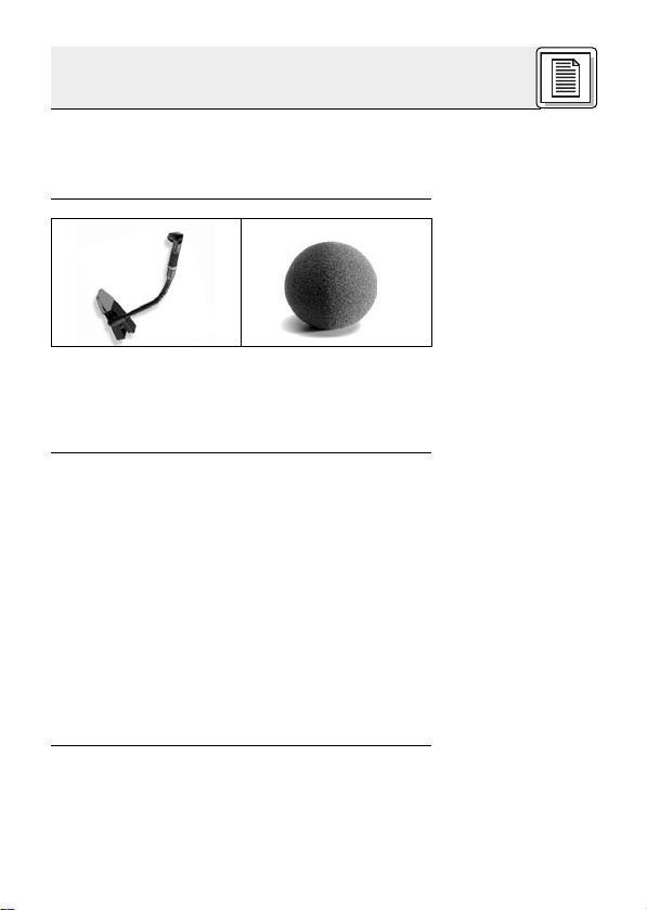
Das C 419
III
ist ein Kondensator-Miniaturmikrofon
mit nierenförmiger Richtcharakteristik. Es
wurde speziell für die Abnahme von Blasinstrumenten und Klavier direkt am Instrument ent-
1 Sicherheitshinweis/Beschreibung
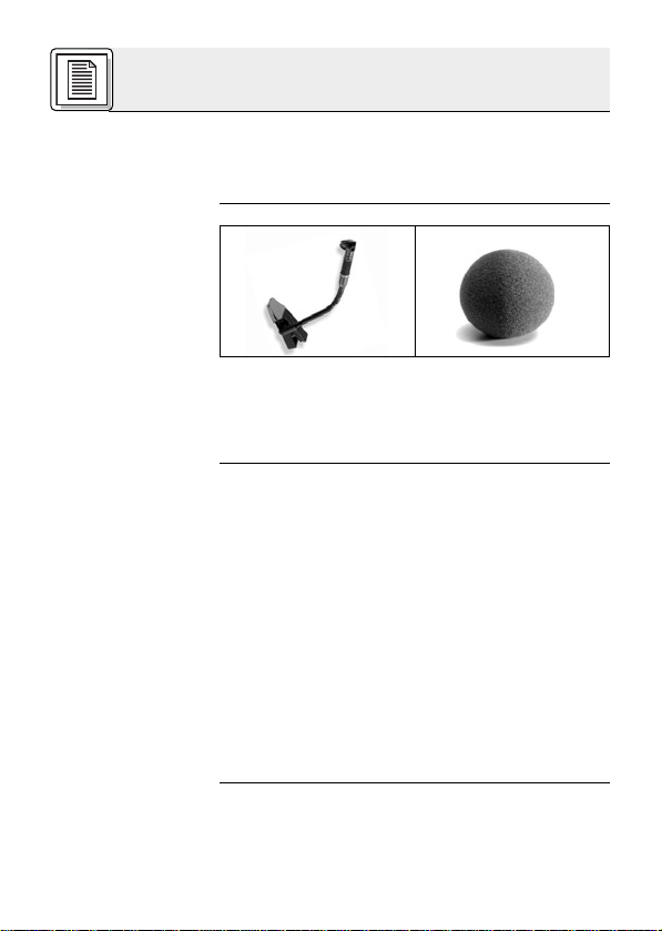
1 C 419
III
1 W 44
Page 3
3
1.5 Varianten
C 419
III
PP
C 419
III
L
1.6 Empfohlenes
Zubehör
wickelt. Ein robuster, gummiüberzogener Clip erlaubt die sichere Befestigung am Instrument. Ein
125 mm langer Schwanenhals ermöglicht eine exakte Positionierung des Mikrofons. Durch seine
nierenförmige, frequenzunabhängige Richtcharakteristik ist das C 419
III
besonders unempfindlich gegen Rückkopplungen und Übersprechen von benachbarten Instrumenten. Durch eine
spezielle elastische Lagerung des Wandlersystems ist das Mikrofon weitgehend unempfindlich
gegen Körperschall. Ein eingebauter Windschutz
reduziert Wind- und Blasgeräusche. Ein externer
Windschutz für zusätzliche Dämpfung von Windund Blasgeräuschen ist im Lieferumfang enthalten.
Das C 419
III
ist in zwei Ausführungen erhältlich:
• Mit 3-poligem XLR-Stecker mit eingebautem
Adapter für Universal-Phantomspeisung von 9
bis 52 V .
•Mit verriegelbarem Mini-XLR-Stecker zum An-
schluss an Battteriespeisegerät B 29 L, Phantomspeiseadapter MPAIII L oder AKG-Taschensender .
1 Beschreibung
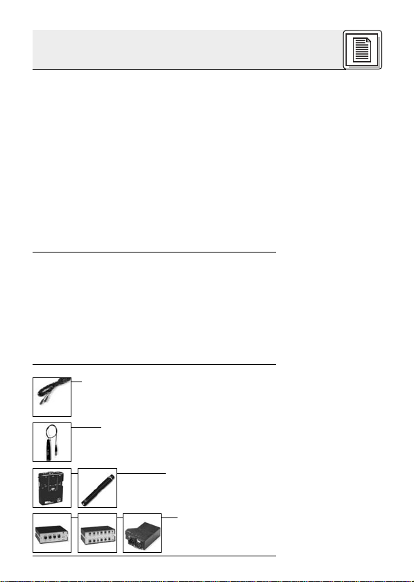
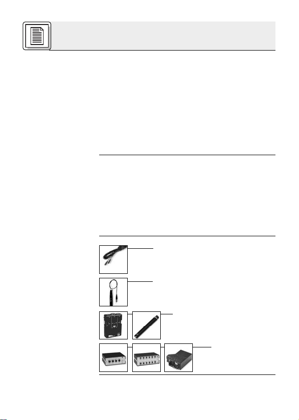
• Mikrofonkabel MK 9/10: 10 m 2-polig
geschirmtes Kabel mit XLR-Stecker
und XLR-Kupplung
• Phantomspeiseadapter MPA III L
• Batteriespeisegeräte
B 29 L, B 15
• Phantomspeisegeräte N 62 E,
N 66 E, B 18
Page 4
4
2.1 Einleitung
Wichtig!
2.2 C 419
III
PP
2.2.1 Anschluss
an symmetri-
sche Eingänge
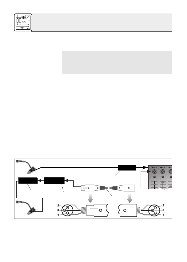
Siehe Abb. 1.
2.2.2 Anschluss
an asymmetri-
sche Eingänge
Das C 419
III
PP/C 419
III
L ist ein Kondensatormi-
krofon und benötigt daher eine Stromversorgung.
Wenn Sie andere als die von AKG empfohlenen Speisegeräte verwenden, kann das
Mikrofon beschädigt werden und erlischt
die Garantie.
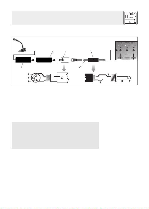
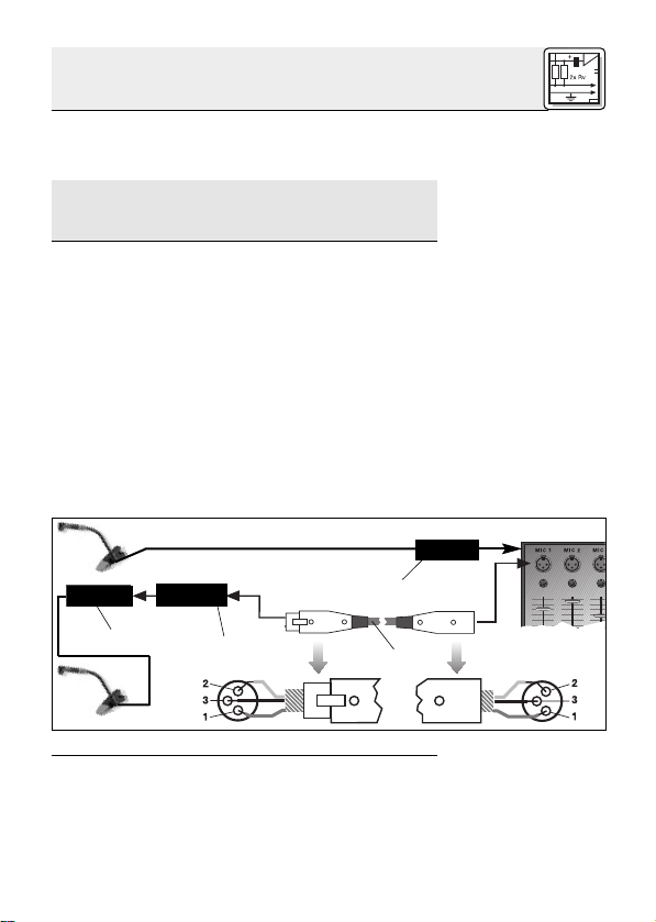
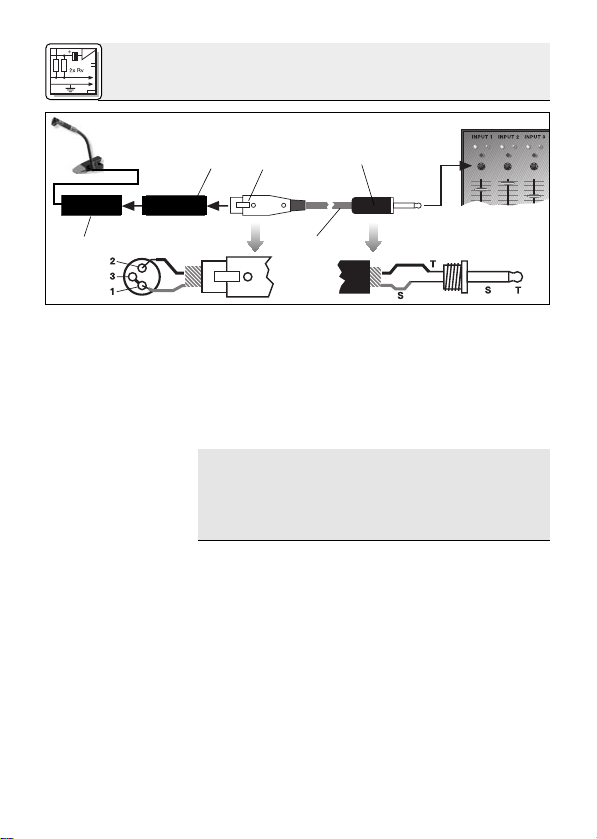
1. Stecken Sie den Phantomspeiseadapter (1) am
Mikrofonkabel an einen symmetrischen XLRMikrofoneingang mit Phantomspeisung an.
2. Schalten Sie die Phantomspeisung ein. (Lesen
Sie dazu in der Betriebsanleitung des jeweiligen Gerätes nach.)
3. Wenn Ihr Mischpult keine Phantom-
speisung besitzt, stecken Sie den
Phantomspeiseadapter (1) an ein optionales
AKG-Phantomspeisegerät (2) (N 62 E, N 66 E,
B 18, B 15) an und verbinden Sie das
Phantomspeisegerät mit Hilfe eines XLRKabels (3) (z.B. AKG MK 9/10 - nicht mitgliefert) mit einem symmetrischen Eingang.
Abb. 1: Anschluss an symmetrischen Eingang
Phantomspeisegeräte (2) von AKG können Sie auch
an einen asymmetrischen Eingang anschließen.
2 Anschluss
XLR
1
2
1
3
Phantom
XLR
Page 5
5
Siehe Abb. 2.
Hinweis:
Verwenden Sie dazu ein Kabel (3) mit XLRStecker (weiblich) und Mono-Klinkenstecker:
Abb. 2: Anschluss an asymmetrischen Eingang
1. Verbinden Sie im XLR-Stecker (4) mittels einer
Drahtbrücke Stift 1 mit Stift 3 und mit der
Abschirmung.
2. Verbinden Sie die innere Ader des Kabels mit
Stift 2 des XLR-Steckers (4) und der Spitze
des Klinkensteckers (5).
Beachten Sie, dass asymmetrische Kabel Einstreuungen aus Magnetfeldern (von Netz- und
Lichtkabeln, Elektromotoren usw .) wie eine Antenne aufnehmen können . Bei Kabeln, die länger als 5 m sind, kann dies zu Brumm- und
ähnlichen Störgeräuschen führen.
2 Anschluss
XLR
Phantom
1
2
3
4
5
Page 6
6
2.3 C 419
III
L
2.3.1 Anschluss
mittels B 29 L
Kabel anstecken:
Siehe Abb. 3.
Kabel abziehen:
Wichtig!
Symmetrischer
Eingang:
Siehe Abb. 3.
Asymmetrischer
Eingang:
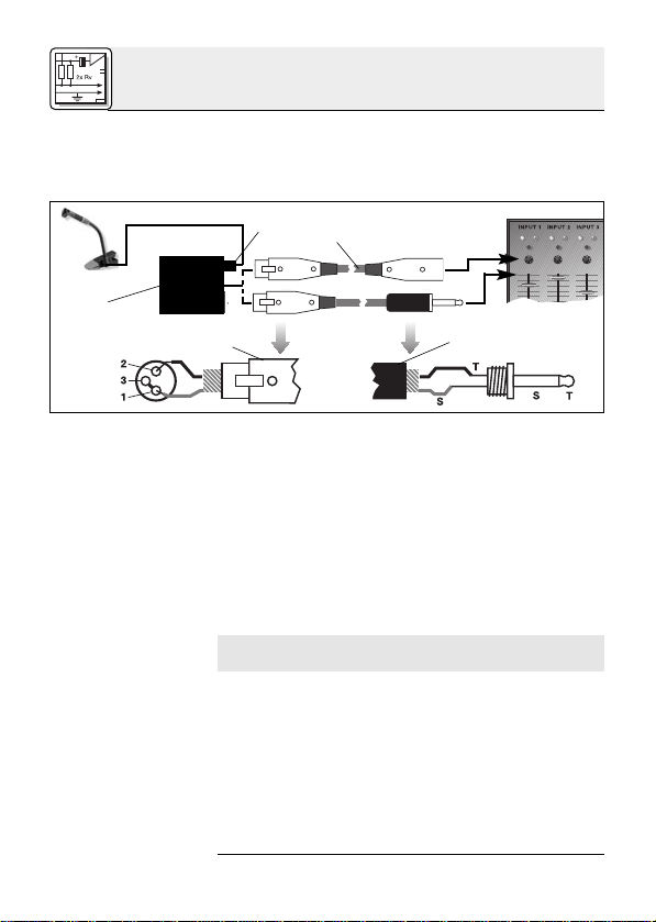
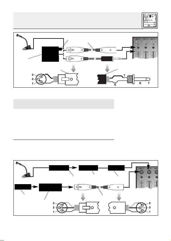
Mit dem optionalen Batteriespeisegerät B 29 L
können Sie das Mikrofon an symmetrische oder
asymmetrische Eingänge ohne Phantomspeisung
anschliessen.
Abb. 3: Anschluss-Schema mit B 29 L
1. Stecken Sie den Mini-XLR-Stecker (1) am
Mikrofonkabel bis zum Anschlag in eine der
beiden Mini-XLR-Buchsen am B 29 L (2).
Der Stecker (1) verriegelt sich automatisch.
Zum Abziehen des Kabels drücken Sie auf
den Entriegelungsknopf am Mini XLR-Stecker
(1) und ziehen Sie den Stecker (1) aus der
Buchse heraus.
Um das Kabel nicht zu beschädigen, ziehen Sie niemals am Kabel selbst!
2. Verbinden Sie das B 29 L (2) mit dem
gewünschten Eingang.
Zum Anschluss an einen symmetrischen
Eingang verwenden Sie ein handelsübliches
XLR-Kabel (3).
Siehe Kapitel 2.2.2.
2 Anschluss
B 29 L
1
2
3
4
5
Page 7
7
2.3.2 Anschluss
mittels MPA III L
Kabel anstecken:
Siehe Abb. 4.
Kabel abziehen:
Siehe Abb. 4.
2.3.3 Anschluss an
Taschensender
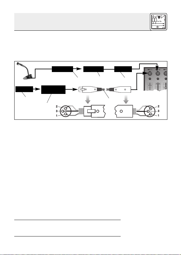
1. Stecken Sie den Mini-XLR-Stecker (1) am
Mikrofonkabel bis zum Anschlag in die MiniXLR-Kupplung (2) am Anschlusskabel des
MPA III L (3).
Der Stecker (1) verriegelt sich automatisch.
Abb. 4: Anschluss-Schema mit MPAIII L
Siehe Kapitel 2.3.1.
2. Stecken Sie den MPA III L (3) an einen symmetrischen XLR-Mikrofoneingang mit
Phantomspeisung an.
3. Schalten Sie die Phantomspeisung ein. (Lesen
Sie dazu in der Betriebsanleitung des jeweiligen Gerätes nach.)
4. Wenn Ihr Mischpult keine Phantom-
speisung besitzt, stecken Sie den MPA III L
(3) an ein optionales AKG-Phantomspeisegerät (4) (N 62 E, N 66 E, B 18, B 15) an und
verbinden Sie das Phantomspeisegerät (4) mit
Hilfe eines XLR-Kabels (5) (z.B. AKG MK 9/10
- nicht mitgliefert) mit einem symmetrischen
Eingang.
Lesen Sie in der Bedienungsanleitung Ihres
Taschensenders nach.
2 Anschluss
Mini XLR Mini XLR MPA
MPA
3
Phantom
4
1
2
3
5
Page 8
8
3.1 Einleitung
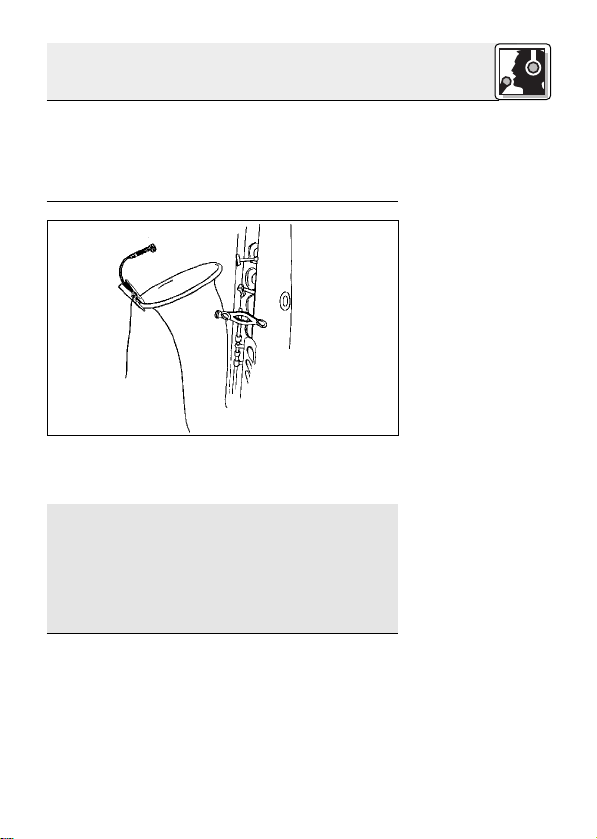
3.2 Saxophon
Abb. 5:
Befestigung des
Mikrofons am
Saxophon
Hinweis:
Hinweis:
Um den ”richtigen” Sound zu finden, müssen Sie
in jedem Fall mit der Mikrofonpositionierung experimentieren. Als Ausgangspunkt dafür sind in den
folgenden Kapiteln bewährte Mikrofontechniken
beschrieben.
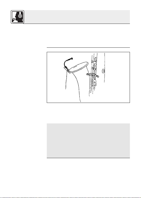
1. Klemmen Sie das Mikrofon am Schallbecher
an.
2. Richten Sie das Mikrofon auf den Rand des
Schallbechers aus.
Für Subtone-Spiel können Sie das Mikrofon
auch auf die Mitte des Schallbechers ausrichten. Dabei werden allerdings starke Luftgeräusche mitübertragen.
Zu starke Klappengeräuschen können Sie
dämpfen, indem Sie einen schmalen Streifen
Schaumstof zwischen Mikrofonklammer und
Instrument einlegen.
3 Anwendung
Page 9
9
3 Anwendung
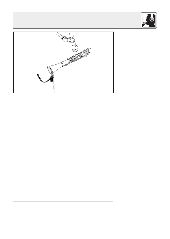
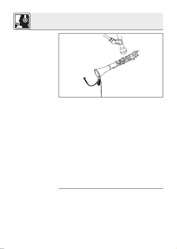
3.3 Klarinette
Abb. 6:
Befestigung des
Mikrofons an der
Klarinette
Alternative:
Da die tieferen Frequenzen über die Klappen, die
hohen Frequenzen aber nur durch die Stürze abgestrahlt werden, empfehlen wir, zwei Mikrofone
zu verwenden:
1. Klemmen Sie das C 419
III
am Schallbecher an.
2. Richten Sie das C 419
III
auf den Rand des
Schallbechers aus.
3. Richten Sie ein stativgebundenes Mikrofon
(z.B. C 5900 oder C 535 von AKG) auf die
Klappen aus.
Wenn Sie kein stativgebundenes Mikrofon verwenden wollen, können Sie auch nur ein C 419
III
allein einsetzen:
1. Klemmen Sie das Mikrofon so an der Schallstürze an, dass das Mikrofon auf die Aussenseite der Klarinette zeigt.
2. Richten Sie das Mikrofon auf die unterste
Klappe aus. In diesem Bereich werden alle Frequenzen etwa gleich stark abgestrahlt.
Page 10
10
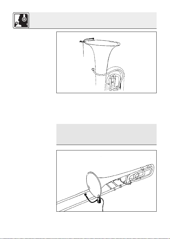
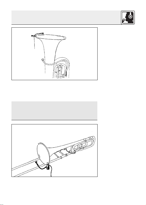
3.4 Tuba, Tenor-
und Baritonhorm
Abb. 7:
Befestigung des
Mikrofons an der
Tuba
Hinweis:
3.5 Posaune
Abb. 8:
Befestigung des
Mikrofons an der
Posaune
1. Klemmen Sie das Mikrofon am Schallbecher
an.
2. Ermitteln Sie durch Versuche die optimale Mikrofonposition.
Bei zu starken Luftgeräuschen richten Sie das
Mikrofon auf den Rand des Schallbechers aus
und/oder stecken Sie den mitgelieferten Windschutz auf das Mikrofon.
1. Klemmen Sie das Mikrofon am Schallbecher
an.
3 Anwendung
Page 11
11
Hinweis:
Hinweis:
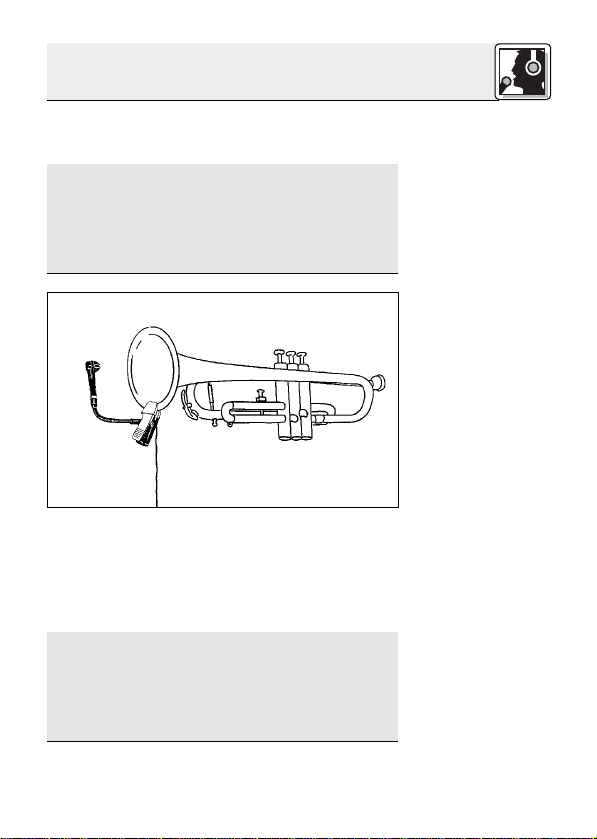
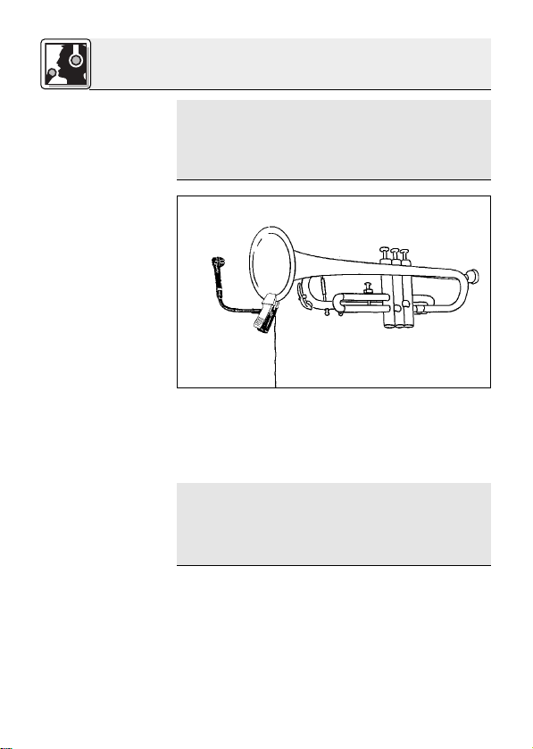
3.6 Trompete
Abb. 9:
Befestigung des
Mikrofons an der
Trompete
Hinweis:
Hinweis:
2. Richten Sie das Mikrofon auf den Rand des
Schallbechers aus.
Wenn Sie mit einem Dämpfer spielen, achten
Sie darauf, den Schwanenhals soweit nach
aussen zu biegen, dass er dem Dämpfer nicht
im Weg ist.
Bei zu starken Luftgeräuschen stecken Sie den
mitgelieferten Windschutz auf das Mikrofon.
1. Klemmen Sie das Mikrofon am Schallbecher
an.
2. Positionieren Sie das Mikrofon so weit wie
möglich vom Instrument weg und richten Sie
es auf den Schallbecher aus.
Wenn Sie mit einem Dämpfer spielen, achten
Sie darauf, den Schwanenhals soweit nach
aussen zu biegen, dass er dem Dämpfer nicht
im Weg ist.
Bei zu starken Luftgeräuschen stecken Sie den
mitgelieferten Windschutz auf das Mikrofon.
3 Anwendung
Page 12

12
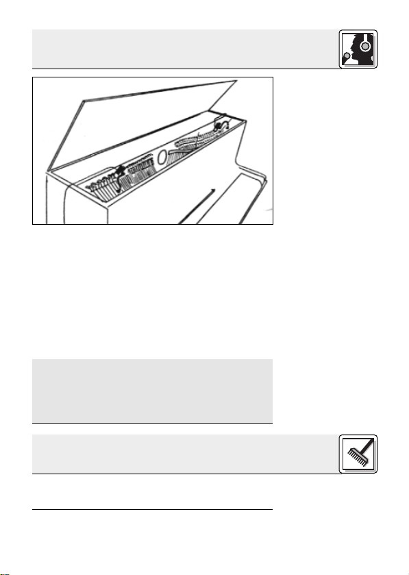
3.7 Klavier
Abb. 10: Abnahme
des Klaviers mit
zwei C 419
III
Hinweis:
Um den vollen Tonumfang des Klaviers zu erfassen, benötigen Sie zwei Mikrofone:
1. Klemmen Sie ein Mikrofon im Bereich der
Basssaiten am Rahmen an.
2. Klemmen Sie das zweite Mikrofon zwischen c2
und c3 am Rahmen an.
3. Richten Sie die beiden Mikrofone so aus, dass
alle Töne mit gleichem Pegel wiedergegeben
werden.
Mechanische Geräusche der Dämpfer können
Sie reduzieren, indem Sie am Mischpult für
beide Mikrofone das Highpass-Filter einschalten. Wenn kein Highpass-Filter zur Verfügung
steht, können Sie auch mit dem EQ vorsichtig
die Tiefen absenken.
Reinigen Sie das Gehäuse des Mikrofons mit einem mit Wasser befeuchteten T uch.
3 Anwendung
4 Reinigung
Page 13
13
5 Fehlerbehebung
Fehler
Kein T on:
Verzerrungen:
Mögliche Ursache
1. Mischpult und/oder
Verstärker ausgeschaltet.
2. Kanal-Fader oder
Summenpegelregler
am Mischpult oder
Lautstärkeregler des
Verstärkers steht auf
Null.
3. Mikrofon nicht an
Mischpult oder
Verstärker angeschlossen.
4. Kabelstecker nicht
richtig angesteckt.
5. Kabel defekt.
6. Keine Speise-
spannung.
1. Gain-Regler am
Mischpult zu weit
aufgedreht.
2. Mischpulteingang zu
empfindlich.
Abhilfe
1. Mischpult und/oder
Verstärker einschalten.
2. Kanal-Fader oder
Summenpegelregler
am Mischpult oder
Lautstärkeregler des
Verstärkers auf gewünschten Pegel
einstellen.
3. Mikrofon an Mischpult oder Verstärker
anschließen.
4. Kabelstecker
nochmals anstecken.
5. Kabel überprüfen
und falls nötig ersetzen.
6. Phantomspeisung
einschalten.
Phantomspeisegerät: ans Netz
anschließen bzw.
Batterie(n) einlegen.
Kabel überprüfen
und falls nötig ersetzen.
1. Gain-Regler zurückdrehen.
2. 10-dB-Vorabschwächung zwischen Mikrofonkabel
und Eingang
stecken.
Page 14
14
6 Technische Daten
Arbeitsweise: Kondensatormikrofon mit
Permanentladung
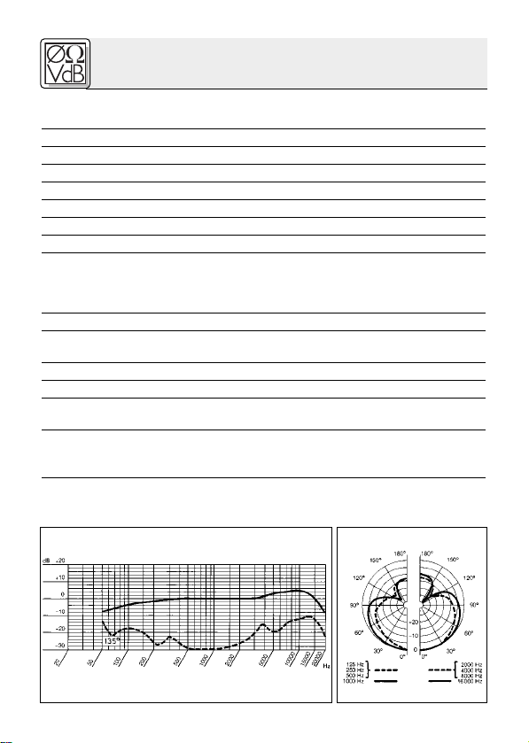
Richtcharakteristik: Niere
Übertragungsbereich: 20 - 20.000 Hz
Empfindlichkeit: 7 mV/Pa (-43 dBV bez. auf 1 V/Pa)
Elektrische Impedanz bei 1000 Hz: 200 Ω
Empfohlene Lastimpedanz: ≥2000 Ω
Grenzschalldruckpegel für 1% / 3% Klirrfaktor: 126 / 130 dB SPL
Äquivalentschalldruckpegel: 31 dB (A) (nach DIN 45412)
Speisespannung: C 41 9
III
PP: 9-52 V Universalphantomspeisung
C 419
III
L: Batteriespeisegerät B 29 L,
Phantomspeiseadapter MPAIII L,
AKG WMS Taschensender
Stromaufnahme: ca. 2 mA
Kabellänge/Steckerart: C 419
III
PP: 3 m / XLR 3-polig
C 419
III
L: 1,5 m / Mini-XLR 3-polig
Oberfläche: mattschwarz
Abmessungen: 180 x 35 mm
Netto/Bruttogewicht: C 419
III
PP: 141 g / 462 g
C 419
III
L: 77 g / 398 g
Dieses Produkt entspricht der Norm EN 50 082-1, vorausgesetzt, dass nachgeschaltete Geräte CE-konform sind.
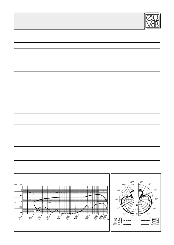
Frequenzgang Polardiagramm
Page 15
15
1.1 Precaution
1.2 Unpacking
1.3 Features
1.4 Brief
Description
Please make sure that the piece of equipment
your microphone will be connected to fulfills the
safety regulations in force in your country and is
fitted with a ground lead.
Check that the packaging contains all of the components listed above. Should anything be missing, please contact your AKG dealer .
• Rugged condenser microphone for instrument
miking on stage.
•Frequency response tailored to wind instrument and piano miking.
• Integrated windscreen for effective suppression
of wind noise.
• Rubber-coated clamp for secure attachment
to the instrument.
• Miniature gooseneck for accurate microphone
alignment.
•Transducer shock mount reduces handling and
cable noise.
•Frequency-independent cardioid polar
response for high gain before feedback.
The C 419
III
is a cardioid miniature condenser microphone. It has been designed specifically
for direct attachment to wind instruments and pianos. A rugged, rubber coated clamp will keep the
microphone securely in place. A 5-inch (125-mm)
1 Precaution/Description
1 C 419
III
1 W 44
Page 16
16
1.5 Versions
C 419
III
PP:
C 419
III
L:
1.6 Optional
Accessories
gooseneck allows you to align the microphone
precisely as required. A frequency-independent
cardioid polar pattern provides high gainbefore-feedback and reduces spillover from
neighboring instruments to a minimum. The transducer is suspended in a dedicated shock mount
for maximum suppression of handling noise. A
built-in windscreen reduces wind and blowing
noise and an external windscreen for additional
wind noise attenuation is included with the microphone.
The C 419
III
is available in two versions:
•With 3-pin XLR connector with integrated adapter for 9 to 52 V universal phantom power .
•With locking mini XLR connector for use with
the B 29 L battery power supply, MPA III L
phantom power adapter, or AKG bodypack
transmitters.
1 Description
• MK 9/10 micr ophone cable: 10-m
(30-ft.) 2-conductor shielded cable
w/male and female XLR connectors
• MPA III L phantom power adapter
• B 29 L, B15 battery power
supplies
• N 62 E, N 66 E,
B 18 phantom
power suppplies
Page 17
17
2.1 Introduction
Important!
2.2 C 419
III
PP
2.2.1 Connecting
to Balanced
Inputs
Refer to fig. 1.
2.2.2 Connecting
to Unbalanced
Inputs
Refer to fig. 2.
The C 419
III
is a condenser microphone and there-
fore needs a power supply .
Using any power supply other than those
recommended by AKG may damage your
microphone and will void the warranty.
1. Connect the phantom power adapter (1) on the
microphone cable to a balanced XLR microphone input with phantom power .
2. Switch the phantom power on. (Refer to the instruction manual of the unit to which you
connected your microphone.)
3. If your mixer provides no phantom power:
Connect the phantom power adapter (1) to an
optional AKG phantom power supply (2) (N 62 E,
N 66 E, B 18, B 15) and use an XLR cable (3)
(e.g., an optional MK 9/10 from AKG) to connect
the phantom power supply to the desired
balanced input.
Fig. 1: Connecting to a balanced input.
You may connect the phantom power supply (2)
to unbalanced inputs, too.
Use a cable (3) with a female XLR connector and
TS jack plug:
2 Interfacing
XLR
1
2
1
3
Phantom
XLR
Page 18
18
Note:
2.3 C 419
III
L
2.3.1 Using the
Optional B 29 L
Connecting the
cable:
Refer to fig. 3.
Disconnecting
the cable:
Fig. 2: Connecting to an unbalanced input.
1. On the XLR connector (4), use a wire bridge to
connect pin 1 to pin 3 and the cable shield.
2. Connect the inside wire of the cable to pin 2
on the XLR connector (4) and the tip contact
of the jack plug (5).
Unbalanced cables may pick up interference
from stray magnetic fields near power or lighting
cables, electric motors, etc. like an antenna.
This may introduce hum or similar noise when
you use a cable that is longer than 16 feet (5 m).
The optional B 29 L battery supply allows you to
connect the microphone to balanced or unbalanced inputs with no phantom power .
1. Push the mini XLR connector (1) on the microphone cable into one of the two mini XLR
sockets on the B 29 L (2) to the stop.
The connector will lock automatically.
To disconnect the cable, press the unlocking
button on the mini XLR connector (1) and pull
the connector (1) out of the socket.
2 Interfacing
XLR
Phantom
1
2
3
4
5
Page 19
19
Important!
Balanced input:
Refer to fig. 3.
Unbalanced input:
2.3.2 Using the
MPA III L
Refer to fig. 4.
Fig. 3: Using the B 29 L to power the microphone.
To avoid damaging the cable, never try to
pull out the cable itself!
2. Connect the B 29 L (2) to the desired input.
Use a commercial XLR cable (3) to connect the
B 29 L (2) to a balanced input.
Refer to section 2.2.2 above.
1. Push the mini XLR connector (1) on the microphone cable into the mini XLR socket (2) on the
cable of the MPAIII L (3) to the stop.
Fig. 4: Connection diagram with MPAIII L.
2 Interfacing
B 29 L
1
2
3
4
5
Mini XLR Mini XLR MPA
MPA
3
Phantom
4
1
2
3
5
Page 20
20
Disconnecting
the cable:
Refer to fig. 4.
2.3.3
Connecting to a
Bodypack
Transmitter
The connector will lock automatically.
Refer to section 2.3.1 above.
2. Connect the MPA III L (3) to a balanced XLR
microphone input with phantom power .
3. Switch the phantom power on. (Refer to the instruction manual of the unit to which you
connected your microphone.)
4. If your mixer provides no phantom power:
Connect the MPA III L (3) to an optional AKG
phantom power supply (4) (N 62 E, N 66 E, B 18,
B 15) and use an XLR cable (5) (e.g., an optional
MK 9/10 from AKG) to connect the phantom
power supply (4) to the desired balanced input.
Refer to the manual of your bodypack transmitter .
2 Interfacing
Page 21
21
3.1 Introduction
3.2 Saxophone
Fig. 5: Microphone
position on the
saxophone.
Note:
Note:
The best way to get the ultimate sound is to experiment with various microphone positions. The
following sections describe proven techniques
that you may want to use as starting points for
your own experiments.
1. Clamp the microphone on the bell.
2. Aim the microphone at the rim of the bell.
For subtone playing, you might like to align the
microphone with the middle of the bell. Be prepared, though, to get a lot of wind noise along
with the saxophone sound.
You can reduce excessive key noise by placing
a narrow strip of foam between the microphone clamp and the instrument.
3 Using Your Microphone
Page 22
22
3.3 Clarinet
Fig. 6: Microphone
position on the
clarinet.
Alternative
technique:
Since the clarinet radiates low frequencies
through the keys and high frequencies through the
bell only, we r ecommend to use two microphones:
1. Clamp the C 419
III
on the bell.
2. Aim the C 419
III
at the rim of the bell.
3. Point a stand-mounted microphone (e.g., a
C 5900 or C 535 from AKG) at the keys.
If you do not wand to use an extra stand-mounted
microphone, you can use a single C 419
III
instead:
1. Clamp the microphone on the bell so that the
microphone will look at the outside of the clarinet.
2. Point the microphone at the lowest key . This is
the only area where all frequencies are radiated
at approximately equal intensity .
3 Using Your Microphone
Page 23
23
3.4 Tuba
Fig. 7: Microphone
position on the
tuba.
Note:
3.5 Trombone
Fig. 8: Microphone
position on the
trombone.
1. Clamp the microphone on the bell.
2. Experiment to find the optimum microphone
position.
If you get too much wind noise, aim the microphone at the rim of the bell and/or slip the
supplied external windscreen on the microphone.
1. Clamp the microphone on the bell.
2. Aim the microphone at the rim of the bell.
3 Using Your Microphone
Page 24
24
Note:
Note:
3.6 Trumpet
Fig. 9: Microphone
position on the
trumpet.
Note:
Note:
If you use a mute, be sure to position the
microphone outside of the bell to clear the
mute.
If you get too much wind noise, slip the supplied external windscreen on the microphone.
1. Clamp the microphone on the bell.
2. Place the microphone as far away from the instrument as possible and aim the microphone
at the bell.
If you use a mute, be sure to position the
microphone outside of the bell to clear the
mute.
If you get too much wind noise, slip the supplied external windscreen on the microphone.
3 Using Your Microphone
Page 25
25
3.7 Piano
Fig. 10: Using two
C 419
III
microphones to mic up
an upright piano.
Note:
The best way to capture the full range of the piano
is to use two microphones:
1. Clamp one microphone on the frame above the
bass strings.
2. Clamp the second microphone on the frame
strut in the octave above Middle C.
3. Align the two microphones so that all notes will
be reproduced at roughly the same level.
You can reduce mechanical noise from the
dampers by switching in the highpass filters on
both microphone channels. If your mixer provides no highpass filters you can use the EQ
cautiously to roll off the low frequencies.
To clean the microphone case, use a soft cloth
moistened with water .
3 Using Your Microphone
4 Cleaning
Page 26

26
5 Troubleshooting
Problem
No sound:
Distortion:
Possible Cause
1. Power to mixer
and/or amplifier is
off.
2. Channel or master
fader on mixer , or
volume control on
amplifier is at zero.
3. Microphone is not
connected to mixer or amplifier .
4. Cable connectors
are seated loosely .
5. Cable is defective.
6. No supply voltage.
1. Gain control on
the mixer set too
high.
2. Mixer input sensitivity too high.
Remedy
1. Switch power to
mixer or amplifier
on.
2. Set channel or
master fader on
mixer or volume
control on amplifier to desired
level.
3. Connect microphone to mixer or
amplifier.
4. Check cable
connectors for secure seat.
5.
Check cable and replace if damaged.
6. Switch phantom
power on.
Phantom power
supply: connect to
power outlet or insert battery
(batteries).
Check cable and replace if necessary.
1. T urn gain control
down CCW.
2. Connect a 10-dB
preattenuation
pad between
microphone cable
and input.
Page 27

27
6 Specifications
Type: pre-polarized condenser microphone
Polar pattern: cardioid
Frequency range: 20 Hz to 20,000 Hz
Sensitivity at 1 kHz: 7 mV/Pa (-43 dBV re 1 V/Pa)
Impedance: 200 Ω
Recommended load impedance: ≥2000 Ω
Max. SPL for 1%/3% THD: 126/130 dB SPL
Equivalent noise level: 31 dB (A) (to DIN 45412)
Power requirement:
C 419
III
PP: 9 to 52 V universal phantom power
C 419
III
L: B 29 L battery power supply,
MPAIII L phantom adapter,
AKG WMS bodypack transmitters
Current consumption: approx. 2 mA
Cable length/Connector: C 419
III
PP: 3 m (10 ft.) / 3-pin male XLR
C 419
III
L: 1.5 m (5 ft.) / 3-pin mini XLR
Finish: matte black
Size: length: 180 mm (7.1 in.); dia.: 35 mm (1.4 in.)
Net/shipping weight: C 419
III
PP: 141 g (5 oz.) / 462 g (16.3 oz.)
C 419
III
L: 77 g (2.7 oz.) / 398 g (14 oz.)
This product conforms to EN 50 082-1 provided it is connected to
equipment with a CE mark.
Frequency Response Polar Diagram
Page 28

28
1.1 Consigne de
sécurité
1.2 Fournitures
1.3
Caractéristiques
particulières
1.4 Description
Vérifiez si l’appareil auquel vous voulez raccorder
le microphone répond aux prescriptions relatives
à la sécurité en vigueur et s’il possède une mise à
la terre de sécurité.
Contrôlez si le carton contient bien tous les éléments énumérés ci-dessus. Si ce n’est pas le cas,
veuillez contacter votre distributeur AKG.
• Microphone électrostatique miniature robuste
pour prise d’instruments sur scène.
• Réponse en fréquence spécialement adaptée
à la prise d’instruments à vent et du piano.
• Bonnette antivent intégrée pour une élimination efficace des bruits de souffle.
• Clip revêtu de caoutchouc pour une fixation
stable sur l’instrument.
• Col-de-cygne miniature pour le positionnement exact du microphone.
• Suspension élastique du système transducteur atténuant efficacement les bruits de manipulation.
• Remarquable immunité au larsen grâce à la caractéristiques de directivité cardioïde indépendante de la fréquence.
Le C 419
III
est un microphone électrostatique miniature cardioïde, conçu spécialement pour la prise
de son directe sur les instruments à vent et le piano.
1 Consigne de sécurité / Description
1 C 419
III
1 W 44
Page 29

29
1.5 Versions
C 419
III
PP
C 419
III
L
1.6 Accessoires
optionnels
Un clip robuste, revêtu de caoutchouc, permet sa
fixation stable sur l’instrument. Le micro peut être positionné avec précision grâce à un col-de-cygne de
125 mm. Sa directivité cardioïde, indépendante
de la fréquence garantit pratiquement l’immunité de
ce micro au Larsen et à la diaphonie pouvant provenir
des autres instruments. Le système transducteur est
monté sur une suspension élastique spéciale rendant
le micro insensible aux vibrations mécaniques. La
bonnette antivent incorporée atténue les bruits de
vent et de souffle. Le micro est fourni avec une seconde bonnette, externe, améliorant encore l’élimination des bruits de vent et de souffle.
Le C 419
III
existe en deux versions :
•Avec connecteur type XLR à trois points, avec
adaptateur incorporé pour alimentation
fantôme universelle de 9 à 52 V .
•Avec connecteur type XLR miniature, verrouillable, pour raccordement à une alimentation à piles
B 29 L, à un adaptateur pour alimentation fantôme
MPA IIIL ou à un émetteur de poche AKG.
1 Description
•
Câble de micro MK 9/10 : câble blindé
bipolaire de 10 m, avec connecteurs
XLR mâle et femelle
• Adaptateur pour alimentation
fantôme MPA III L
• Alimentations à piles
B 29 L, B 15
•
Appareils d’alimenta-
tion fantôme
N 62 E,
N 66 E, B 18
Page 30

30
2.1 Introduction
Important!
2.2 C 419
III
PP
2.2.1
Raccordement
sur une entrée
symétrique
Voir Fig. 1.
Le C 419
III
PP/C 419
III
L est un microphone élec-
trostatique ; il a donc besoin d’une alimentation.
L’utilisation d’alimentations autres que celles recommandées par AKG peut provoquer
des dégâts sur le micro et entraîne la perte
de la garantie.
1. Connectez l’adaptateur pour alimentation
fantôme du câble micro sur une entrée de
micro symétrique type XLR avec alimentation
fantôme.
2. Mettez l’alimentation fantôme sous tension
(Veuillez vous reporter à la notice de l’alimentation utilisée).
Fig. 1 : Raccordement sur une entrée symétrique
3. Si vous n’avez pas d’alimentation
fantôme sur votre table de mixage, branchez l’adaptateur pour alimentation fantôme
(1) sur une alimentation fantôme AKG optionnelle (2) (N 62 E, N 66 E, B 18, B 15) et raccordez l’alimentation fantôme à une entrée
symétrique à l’aide d’un câble XLR (3) (p.ex.
AKG MK 9/10 – n’est pas fourni avec le micro).
2 Raccordement
XLR
1
2
1
3
Phantom
XLR
Page 31

31
2.2.2
Raccordement
sur une entrée
asymétrique
N.B.
2.3 C 419
III
L
2.3.1
Raccordement
au moyen du
B 29 L
Brancher le câble:
Voir Fig. 3.
Vous pouvez aussi connecter les alimentations fantôme
d’AKG (2) sur une entrée asymétrique.
Il vous faut un câble (3) avec une fiche XLR femelle
et une fiche à jack mono:
Fig. 2 : Raccordement sur une entrée asymétrique
1. Pontez les contacts 1 et 3 de la fiche XLR (4) et
reliez-les au blindage du câble.
2. Reliez le conducteur interne du câble au
contact 2 de la fiche XLR (4) et à la pointe de la
fiche à jack (5).
Les câbles asymétriques peuvent capter
comme une antenne les interférences de
champs magnétiques (câbles lumière ou force,
moteurs électriques, etc.). Si le câble mesure
plus de 5 m ce phénomène pourra se traduire
par des ronflements et autres parasites.
L’alimentation à pile B 29 L optionnelle vous permet de raccorder le micro à des entrées symétriques ou asymétriques sans alimentation fantôme.
1. Enfoncez le connecteur mini-XLR (1) du câble
du micro à fond dans une des deux embases
mini-XLR du B 29 L (2).
Le connecteur (1) se verrouille automatiquement.
2 Raccordement
XLR
Phantom
1
2
3
4
5
Page 32

32
Débrancher le
câble :
Important !
Entrée symétrique:
Cf. Fig. 3.
Entrée asymétrique:
2.3.2
Raccordement
avec MPA III L
Brancher le câble:
Voir Fig. 4.
Débrancher le
câble :
Pour détacher le câble, appuyez sur le bouton
de déverrouillage du connecteur mini-XLR (1)
et sortez le connecteur de la prise.
Pour ne pas risquer d’abîmer le câble, ne
sortez jamais le connecteur en tirant sur
le câble.
Fig. 3 : Schéma de raccordement avec B 29 L
2. Raccordez le B 29 L (2) sur l’entrée voulue.
Pour le raccordement sur une entrée symétri-
que, utilisez un câble XLR (3) en vente dans le
commerce.
Voir point 2.2.2.
1. Enfoncez le connecteur mini-XLR (1) du câble
micro jusqu’en butée dans l’accouplement
mini-XLR (2) du câble de raccordement du
MPA IIIL (3).
Le connecteur (1) se verrouille automatiquement.
Voir point 2.3.1.
2. Connectez l’MPA III L (3) sur une entrée de
micro symétrique type XLR avec alimentation
fantôme.
2 Raccordement
B 29 L
1
2
3
4
5
Page 33

33
Voir Fig. 4.
2.3.3
Raccordement
sur un émetteur
de poche
Fig. 4: Schéma de raccordement avec MP A III L
3. Mettez l’alimentation fantôme sous tension
(Veuillez vous reporter à la notice de l’alimentation utilisée).
4. Si vous n’avez pas d’alimentation
fantôme sur votre table de mixage, branchez l’MPA III L (3) sur une alimentation
fantôme AKG optionnelle (4) (N 62 E, N 66 E, B
18, B 15) et raccordez l’alimentation fantôme à
une entrée symétrique à l’aide d’un câble XLR
(5) (p.ex. AKG MK 9/10 – n’est pas fourni avec
le micro).
Conformez-vous aux instructions du mode d’emploi de votre émetteur de poche.
2 Raccordement
Mini XLR Mini XLR MPA
MPA
3
Phantom
4
1
2
3
5
Page 34

34
3.1 Introduction
3.2 Saxophone
Fig. 5: Fixation du
micro sur le
saxophone
Remarque :
Remarque :
Vous n’obtiendrez sans doute pas du premier
coup "le" son souhaité. Il faut normalement essayer différentes positions du micro. Pour vous aider nous décrivons ci-dessous quelques techniques de positionnement éprouvées.
1. Fixez le micro sur le pavillon du saxophone.
2. Orientez le micro vers le bord du pavillon.
Si vous voulez jouer en subtone, vous pouvez
également orienter le micro vers le centre du
pavillon. Cependant, dans ce cas, les bruits de
souffle s’entendront plus.
Vous pouvez atténuer les bruits de clefs
gênants en introduisant une mince bande de
mousse entre la pince du micro et l’instrument.
3 Utilisation
Page 35

35
3.3 Clarinette
Fig. 6: Fixation du
micro sur la
clarinette
Voir Fig. 6.
Autre solution :
Les basses fréquences se propageant par les
clefs alors que les hautes fréquences se propagent uniquement par le pavillon, nous conseillons
d’utiliser deux micros :
1. Fixez le C 419III sur le pavillon.
2. Orientez le C 419III vers le bord du pavillon.
3. Orientez un micro sur pied (p.ex. C 5900 ou C
535 d’AKG) sur les clefs.
Si vous ne voulez pas utiliser de micro sur pied,
vous pouvez aussi opérer avec un seul C 419III :
1. Fixez le micro sur le pavillon en le dirigeant sur
la face extérieure de la clarinette.
2. Dirigez le micro sur la clef inférieure au niveau
de laquelle toutes les fréquences ont à peu
près la même intensité.
3 Utilisation
Page 36

36
3.4 Tuba
Fig. 7 : Fixation du
micro sur le tuba
Remarque:
3.5 Trombone
Fig. 8 : Fixation du
micro sur le
trombone
1. Fixez le micro sur le pavillon.
2. Faites différents essais pour trouver la position
optimale du micro.
Si les bruits de souffle sont trop forts orientez
le micro sur le bord du pavillon et/ou mettez la
bonnette fournie sur le micro.
1. Fixez le micro sur le pavillon.
2. Orientez le micro sur le bord du pavillon.
3 Utilisation
Page 37

37
Remarque :
Remarque:
3.6 Trompette
Fig. 9 : Fixation du
micro sur la
trompette
Remarque :
Remarque:
Si vous utilisez une sourdine, incurvez le colde-cygne vers l’extérieur pour qu’il ne gêne
pas pour mettre la sourdine.
Si les bruits de souffle sont trop forts, mettez la
bonnette fournie sur le micro.
1. Fixez le micro sur le pavillon.
2. Eloignez le micro au maximum de l’instrument
et orientez-le sur le pavillon.
Si vous utilisez une sourdine, incurvez le colde-cygne vers l’extérieur pour qu’il ne gêne
pas pour mettre la sourdine.
Si les bruits de souffle sont trop forts, mettez la
bonnette fournie sur le micro.
3 Utilisation
Page 38

38
3.7 Piano
Fig. 10 : Prise de
son sur le piano à
l’aide de deux
C 419
III
Remarque :
Pour capter toute l’étendue du piano, vous avez
besoin de deux micros :
1. Fixez un micro sur le cadre au niveau des cordes des basses.
2. Fixez le second micro sur le cadre entre do4 et
do5.
3. Orientez les deux micros de manière à ce que
tous les sons soient rendus au même niveau.
Vous pouvez réduire les bruits mécaniques des
étouffoirs en insérant le filtre passe-haut pour
les deux micros sur la table de mixage. Si vous
ne disposez pas d’un filtre passe-haut, vous
pouvez atténuer les basses en réglant finement l’EQ.
Le boîtier du micro se nettoie avec un chiffon
légèrement humide (eau claire).
3 Utilisation
4 Nettoyage
Page 39

39
5 Dépannage
Problème
Pas de son :
Distorisons :
Cause possible
1. La console de mixage
et/ou l’amplificateur ne
sont pas sous tension.
2. Le fader du canal ou le
réglage de niveau master de la console de
mixage ou le réglage
de niveau sonore de
l’ampli est sur zéro.
3. Le micro n’est pas
connecté à la console
de mixage ou à l’ampli.
4. La fiche est mal enfoncée.
5. Le câble est abîmé.
6. Pas de tension d’alimentation.
1. Le réglage de gain de
la table de mixage est
trop haut.
2. L’entrée de la table de
mixage est trop sensible.
Remède
1. Mettre la console de
mixage et/ou l’amplificateur sous tension.
2. Régler le fader du canal ou le réglage de niveau master de la console de mixage ou le
réglage de niveau sonore de l’ampli sur la
valeur voulue.
3. Connecter le micro à la
console de mixage ou
à l’ampli.
4. Enfoncer la fiche correctement.
5. Contrôler le câble et le
remplacer le cas
échéant.
6. Mettre l’alimentation
fantôme sous tension.
Appareil d’alimentation
fantôme : brancher sur
le secteur ou mettre
une (des) pile(s).
Contrôler le câble et le
remplacer le cas
échéant.
1. Baisser le réglage de
gain.
2. Insérer un pré-atténuateur de sensibilité entre
le câble du micro et
l’entrée.
Page 40

40
6 Caractéristiques techniques
Fonctionnement: microphone électrostatique à charge per-
manente
Directivité: cardioïde
Réponse en fréquence: 20 … 20.000 Hz
Sensibilité : 7 mV/Pa (-43 dBV rapp. à 1 V/Pa)
Impédance électrique à 1.000 Hz: 200 Ω
Impédance de charge recommandée: ≥2000 Ω
Niveau maximum de pression sonore pour un facteur
de distorsion de 1% / 3%: 126 / 130 dB SPL
Niveau de bruit équivalent: 31 dB (A) (selon DIN 45412)
Tension d’alimentation: C 419
III
PP: 9 … 52 V, al. fantôme universelle
C 419
III
L: alimentation à piles B 29 L,
adaptateur fantôme MPAIII L,
émetteurs de poche AKG WMS
Consommation: env. 2 mA
Connecteur: C 41 9
III
PP: 3 m / type XLR, 3 points
C 419
III
L: 1,5 m / type mini-XLR, 3 points
Couleur: noir mat
Dimensions: 180 x 35 mm
Poids net/brut : C 419
III
PP: 141 g /462 g
C 419
III
L: 77 g / 398 g
Ce produit est conforme à la norme EN 50 082-1 à condition que les appareils en
aval soient aux normes européennes.
Réponse en fréquence Diagramme polaire
Page 41

41
1.1 Indicazione
per la sicurezza
1.2. In dotazione
1.3.
Caratteristiche
particolari
1.4 Breve
descrizione
Controllate per favore se l’apparecchio che volete
collegare al microfono corrisponde alle norme di
sicurezza vigenti e se è dotato di una messa a
terra di sicurezza.
Controllate per favore se la confezione contiene
tutti i componenti di cui sopra. Se manca qualcosa rivolgetevi al vostro rivenditore AKG.
• Robusto microfono a condensatore per la ripresa strumentale in palco.
• Risposta in frequenza specialmente ideata per
la ripresa di strumenti a fiato e pianoforti.
• Antisoffio integrato per sopprimere in modo efficace i rumori prodotti dai fiati.
• Clip rivestito in gomma per fissare il microfono
in modo stabile sullo strumento.
• Collo di cigno in miniatura per posizionare il
microfono in modo esatto.
• Sospensione elastica del sistema trasduttore
per sopprimere in modo efficace le vibrazioni
meccaniche.
• Alta sicurezza contro il feedback, grazie alla direttività cardioide indipendente dalla frequenza.
Il C 419
III
è un microfono miniaturizzato a condensatore con una direttività cardioide. È stato sviluppato appositamente per la ripresa di strumenti a fiato
1 Indicazione per la sicurezza / Descrizione
1 C 419
III
1 W 44
Page 42

42
1.5 Varianti
C 419
III
PP
C 419
III
L
1.6 Accessori
raccomandati
e pianoforti direttamente sullo strumento. Un robusto clip rivestito di gomma permette di fissarlo in
modo sicuro sullo strumento. Un collo di cigno lungo
125 mm permette di posizionare il microfono esattamente. Grazie alla sua direttività cardioide, indipendente dalla frequenza, il C 419
III
è particolarmente insensibile contro feedback e leakage di strumenti vicini. La speciale sospensione elastica del
trasduttore rende il microfono largamente insensibile
contro le vibrazioni meccaniche. L’antisoffio integrato riduce i rumori prodotti dal vento e dai fiati. Un
antisoffio esterno per l’ulteriore riduzione dei rumori
da vento e da fiati è in dotazione.
Il C 419
III
è disponibile in due varianti:
• Con connettore XLR a 3 poli con adattatore in-
corporato per l’alimentazione phantom universale da 9 a 52 V .
• Con connettore mini-XLR arrestabile per il col-
legamento all’alimentatore a batteria B 29 L,
all’adattatore per l’alimentazione phantom
MPA IIIL o ai trasmettitori da tasca AKG.
1 Descrizione
• Cavo microfonico MK 9/10: cavo lungo
10 m, schermato, a 2 poli, con connet-
tore XLR e accoppiamento XLR.
• Adattatore phantom MPA III L
• Alimentatori a batteria
B 29 L, B 15
• Alimentatori
phantomN 62 E,
N 66 E, B 18
Page 43

43
2.1 Introduzione
Importante!
2.2 C 419
III
PP
2.2.1
Collegamento
ad ingressi
simmetrici
Vedi fig. 1.
Il C 419
III
è un microfono a condensatore e ha
quindi bisogno di alimentazione.
Se usate alimentatori diversi da quelli raccomandati dall’AKG, il microfono può subire danni e la garanzia si estingue.
1. Collegate l’adattatore per l’alimentazione
phantom disposto sul cavo microfonico a un
ingresso microfonico XLR simmetrico con alimentazione phantom.
2. Inserite l’alimentazione phantom. (Leggete in
merito le istruzioni per l’uso del rispettivo apparecchio.)
Fig. 1: Collegamento ad un ingresso simmetrico
3. Se il vostro mixer non è dotato di alimen-
tazione phantom, inserite l’adattatore per alimentazione phantom (1) in un alimentatore
phantom AKG opzionale (2) (N 62 E, N 66 E,
B 18, B 15) e collegate l’alimentatore phantom
servendovi di un cavo XLR (3) (p.e. AKG
MK 9/10 – non in dotazione) ad un ingresso
simmetrico.
2 Collegamento
XLR
1
2
1
3
Phantom
XLR
Page 44

44
2.2.2
Collegamento
ad ingressi
asimmetrici
Vedi fig. 2.
Nota:
2.3 C 419
III
L
2.3.1
Collegamento
con B 29 L
Gli alimentatori phantom (2) dell’AKG possono venir collegato anche ad un ingresso asimmetrico.
Usate un cavo (3) con una presa XLR (4) e una
spina jack mono (5):
Fig. 2: Collegamento ad un ingresso asimmetrico
1. Nella presa XLR (4), collegate con un ponte a
filo i contatti 1 e 3 e portateli sullo schermo del
cavo.
2. Collegate il conduttore interno del cavo con il
contatto 2 della presa XLR (4) e la punta della
spina jack (5).
Tenete presente che i cavi asimmetrici possono assorbire, come un’antenna, irradiazioni
da campi magnetici (cavi di rete, cavi della
luce, elettromotori ecc.). Nel caso di cavi la cui
lunghezza supera i 5 m, questo fenomeno può
causare ronzìi ed altri rumori disturbanti.
Con l’alimentatore a batterie opzionale B 29 L potete collegare il microfono ad ingressi simmetrici o
asimmetrici senza alimentazione phantom.
2 Collegamento
XLR
Phantom
1
2
3
4
5
Page 45

45
Inserire il cavo:
Vedi fig. 3.
Sfilare il cavo:
Importante!
Ingresso
simmetrico:
Vedi fig. 3.
Ingresso
asimmetrico:
2.3.2
Collegamento
con MPA III L
Inserire il cavo:
Vedi fig. 4.
Sfilare il cavo:
Fig. 3: Schema di collegamento con B 29 L
1. Inserite il connettore mini-XLR (1) sul cavo
microfonico in una delle due prese mini-XLR
sul B 29 L (2) fino all’arresto.
Il connettore (1) si blocca automaticamente.
Per sfilare il cavo, premete il bottone di sblocco
sul connettore mini-XLR (1) e sfilate il connettore (1) dalla presa.
Per non danneggiare il cavo, non esercitate mai trazione direttamente sul cavo!
2. Collegate il B 29 L (2) con l’ingresso prescelto.
Per il collegamento ad un ingressso simme-
trico servitevi di un cavo XLR commerciale (3).
Vedi capitolo 2.2.2.
1. Inserite il connettore mini-XLR (1) disposto sul
cavo microfonico fino all‘arresto nell‘accoppiamento mini-XLR (2) disposto sul cavo di collegamento dell’MPA IIIL (3).
Il connettore (1) si blocca automaticamente.
Vedi capitolo 2.3.1.
2 Collegamento
B 29 L
1
2
3
4
5
Page 46

46
Vedi fig. 4.
2.3.3
Collegamento
ad un trasmetti-
tore da tasca
Fig. 4: Schema di collegamento con MPAIII L
2. Collegate l’MPA III L (3) disposto sul cavo
microfonico a un ingresso microfonico XLR
simmetrico con alimentazione phantom.
3. Inserite l’alimentazione phantom. (Leggete in
merito le istruzioni per l’uso del rispettivo apparecchio.)
4. Se il vostro mixer non è dotato di alimen-
tazione phantom, inserite l’MPA III L (3) in un
alimentatore phantom AKG opzionale (4) (N 62 E,
N 66 E, B 18, B 15) e collegate l’alimentatore
phantom (4) servendovi di un cavo XLR (5) (p.e.
AKG MK 9/10 – non in dotazione) ad un ingresso simmetrico.
Leggete al riguardo le istruzioni per l’uso del vostro trasmettitore da tasca.
2 Collegamento
Mini XLR Mini XLR MPA
MPA
3
Phantom
4
1
2
3
5
Page 47

47
3.1 Introduzione
3.2 Sassofono
Fig. 5: Fissaggio
del microfono sul
sassofono
Indicazione:
Indicazione:
Per trovare il sound giusto dovete in ogni caso
sperimentare la posizione del microfono. Nei capitoli seguenti sono descritte provate tecniche
microfoniche che possono esservi d’aiuto.
1. Fissate il microfono sulla campana dello strumento.
2. Puntate il microfono sul margine della campana.
Per suonare subtone, potete puntare il microfono anche sul centro della campana; in questo caso vengono però trasmessi anche forti
rumori prodotti dall’aria.
Rumori troppo forti delle chiavette possono
essere attenuati inserendo una sottile striscia
di spugna tra il clip del microfono e lo strumento.
3 Impieghi
Page 48

48
3.3. Clarinetto
Fig. 6: Fissaggio
del microfono
sul clarinetto
In alternativa:
Poiché le frequenze più basse vengono emesse
attraverso le chiavette, le frequenze alte però solo
dalla campana, vi raccomandiamo di usare due
microfoni:
1. Fissate il C 419
III
sulla campana.
2. Puntate il C 419
III
sul margine della campana.
3. Puntate un microfono montato su un supporto
(p.e. C 5900 oppure C 535 della AKG) sulle
chiavette.
Se non volete usare un microfono con supporto
potete usare anche un solo C 419
III
:
1. Fissate il microfono sulla campana in modo
tale che il microfono punti sul lato esterno del
clarinetto.
2. Puntate il microfono sulla chiavetta più in
basso. In questo campo tutte le frequenze vengono emesse in modo all’incirca uguale.
3 Impieghi
Page 49

49
3.4 Tuba
Fig. 7: Fissaggio
del microfono sulla
tuba
Indicazione:
3.5 Trombone
Fig. 8: Fissaggio
del microfono sul
trombone
1. Fissate il microfono sulla campana.
2. Trovate la posizione ottimale del microfono
sperimentandola.
In caso di rumori troppo forti prodotti dall’aria,
puntate il microfono sul margine della campana e/o infilate l’antisoffio in dotazione sul
microfono.
1. Fissate il microfono sulla campana.
2. Puntate il microfono sul margine della campana.
3 Impieghi
Page 50

50
Indicazione:
Indicazione:
3.6. Tromba
Fig. 9: Fissaggio
del microfono sulla
tromba
Indicazione:
Indicazione:
Se suonate con la sordina, state attenti a piegare il collo di cigno in modo che non sia d’intralcio alla sordina.
In caso di rumori troppo forti prodotti dall’aria
infilate l’antisoffio in dotazione sul microfono.
1. Fissate il microfono sulla campana.
2. Posizionate il microfono il più lontano possibile
dallo strumento e puntatelo sulla campana.
Se suonate con la sordina, state attenti a piegare il collo di cigno in modo che non sia d’intralcio alla sordina.
In caso di rumori troppo forti prodotti dall’aria
infilate l’antisoffio in dotazione sul microfono.
3 Impieghi
Page 51

51
3.7 Pianoforte
Fig. 10: Ripresa del
pianoforte con due
C 419
III
Indicazione:
Per poter riprendere la piena sonorità del pianoforte, avete bisogno di due microfoni:
1. Fissate un microfono nella zona delle corde di
bordone sul telaio.
2. Fissate il secondo microfono tra il do4 e il do5
sul telaio.
3. Puntate i due microfoni in modo che tutti i
suoni vengano riprodotti con lo stesso livello
sonoro.
I rumori meccanici delle sordine possono venir
ridotti inserendo sul mixer il filtro highpass per
ambedue i microfoni. Se non è a disposizione
un filtro higpass potete anche ridurre i bassi
con l’EQ procecendo con cautela.
Pulite la scatola del microfono con un panno inumidito con acqua.
3 Impieghi
4 Pulizia
Page 52

52
5 Eliminazione di difetti
Difetto
Nessun suono:
Distorsioni:
Possibili cause
1. Mixer e/o amplificatore sono disinseriti.
2. Fader del canale o regolatore principale
del mixer o regolatore
del volume dell’amplificatore sono in posizione zero.
3. Il microfono non è
collegato al mixer o
all’amplificatore.
4. Il connettore del cavo
non è inserito bene.
5. Il cavo è difettoso.
6. Non c’è alimentazione.
1. Il regolatore gain sul
mixer è aperto
troppo.
2. L’ingresso del mixer è
troppo sensibile.
Rimedio
1. Inserire il mixer e/o
l’amplificatore.
2. Portare al livello desiderato il fader del canale o il regolatore
principale del mixer o
il regolatore del volume dell’amplificatore.
3. Collegare il microfono
al mixer o all’amplificatore.
4. Inserire di nuovo il
connettore del cavo.
5. Controllare il cavo e
sostituirlo se necessario.
6. Inserire l’alimentazione phantom.
Alimentatore phantom: collegarlo alla
rete oppure inserire
batteria(e).
Controllare il cavo e,
se necessario, sostituirlo.
1. Portare indietro il regolatore gain.
2. Inserire un preattenuatore di 10 dB tra cavo
microfonico ed ingresso.
Page 53
53
6 Dati tecnici
Modo di funzionamento: microfono a condensatore con carica per-
manente
Direttività: cardioide
Risposta in frequenza: 20 - 20.000 Hz
Sensibilità: 7 mV/Pa (-43 dBV rif. a 1 V/Pa)
Impedenza elettrica a 1000 Hz: 200 Ω
Impedenza di carico raccomandata: ≥2000 Ω
Livello di pressione acustica limite per un coefficiente di distorsione armonica
di 1% / 3%: 126 / 130 dB SPL
Livello di pressione acustica equivalente: 31 dB (A) (secondo DIN 45412)
Tensione di alimentazione: C 419
III
PP: al. phantom universale 9 - 52 V
C 419
III
L: alimentatore a batterie B 29 L,
adattatore phantom MPAIII L,
trasmettitori da tasca AKG WMS
Assorbimento: 2 mA circa
Lunghezza del cavo / connettore: C 419
III
PP: 3 m / XLR a 3 poli
C 419
III
L: 1,5 m / mini-XLR a 3 poli
Superficie: nero opaco
Dimensioni: 180 x 35 mm
Peso netto/lordo: C 419
III
PP: 141 g / 462 g
C 419
III
L: 77 g / 398 g
Questo prodotto corrisponde alla norma EN 50 082-1, presupposto che gli appa-
recchi collegati siano conformi alle norme CE.
Risposta in frequenza Diagramma polare
Page 54

54
1.1 Indicaciones
de seguridad
1.2 Volumen de
suministro
1.3
Características
especiales
1.4 Breve
descripción
Sírvase verificar si el aparato al cual quiere conec-
tar el micrófono cumple con las disposiciones
de seguridad vigentes y está equipado con
una toma de tierra de seguridad.
Sírvase controlar si el embalaje contiene todas las
piezas indicadas arriba. Si falta algo, le rogamos dirigirse a su distribuidor AKG.
• Robusto micrófono de condensador para recepción de instrumentos musicales en el escenario.
• Respuesta de frecuencia especialmente concebida para la recepción de instrumentos de viento
y pianos.
• Pantalla antiviento integrada para la eficaz represión de ruidos de soplido.
• Clip de sujeción con recubrimiento plástico para
fijar el micrófono en el instrumento.
• Brazo flexible en miniatura para posicionar el
micrófono con exactitud.
• Suspensión elástica del transductor para una eficaz represión de ruidos vibracionales.
• Elevada seguridad ante la retroalimentación por
la característica direccional cardioide independiente de la frecuencia.
El C 419
III
es un minimicrófono de condensador con
característica direccional cardioide especialmente diseñado para la recepción de instrumentos de
1 Indicaciones de seguridad / Descripción
1 C 419
III
1 W 44
Page 55

55
1.5 Variantes
C 419
III
PP
C 419
III
L
1.6 Accesorios
opcionales
viento y pianos. Posee un robusto clip con recubrimiento plástico para su segura fijación en el instrumento y un brazo flexible de 125 mm para su exacto
posicionamiento. Por su característica direccional
cardioide independiente de la frecuencia, es muy
insensible a la retroalimentación y a los sonidos de
otros instrumentos cercanos. La suspensión elástica
especial del transductor reprime eficazmente los ruidos vibracionales. La pantalla antiviento integrada al
micrófono reduce los ruidos de viento y de soplido.
Con la pantalla antiviento externa incluida en el suministro es posible amortiguar aun más los ruidos de soplido o de viento.
El C 419
III
puede adquirirse en dos modelos:
• Con conector XLR de 3 polos y con adaptador incorporado para alimentación fantasma universal
de 9 a 52 V .
• Con conector mini-XLR enclavable para la conexión al alimentador de batería B 29 L, al adaptador de alimentación fantasma MPA IIIL o un emisor de bolsillo AKG.
1 Descripción
• Cable de micrófono MK 9/10: 10 m
de cable bipolar apantallado con
conector y acoplamiento XLR.
• Adaptador de alimentación fantasma
MPA III L
• Alimentadores por batería
B 29 L, B 15
• Alimentadores
fantasma N 62 E,
N 66 E,B 18
Page 56

56
2.1 Introducción
¡Importante!
2.2 C
419
III
PP
2.2.1 Conexión a
entradas
balanceadas
Ver Fig. 1.
El C
419
III
es un micrófono de condensador y ne-
cesita, por lo tanto, alimentación de corriente.
Si se utilizan alimentadores diferentes a
los recomendados por AKG puede dañarse
el micrófono, cesando con ello la garantía.
1. Conecte el adaptador de alimentación fantasma del cable del micrófono a una entrada
de micrófono XLR balanceada con alimentación fantasma.
Fig. 1: Conexión a entrada balanceada
2. Concecte la alimentación fantasma (consulte
para ello el Modo de empleo del aparato correspondiente).
3. Si su pupitre de mezclas no tiene ali-
mentación fantasma, enchufe el adaptador
de alimentación fantasma (1) al alimentador de
tensión fantasma de AKG opcional (2) (N 62 E,
N 66 E, B 18, B 15) y conecte luego el alimentador de tensión fantasma a una entrada balanceada utilizando un cable XLR (3) (por ej.:
AKG MK 9/10 - no incluido en el suministro).
2 Conexión
XLR
1
2
1
3
Phantom
XLR
Page 57

57
2.2.2 Conexión a
entradas no
balanceadas
Ver Fig. 2.
Nota:
2.3 C 419III L
2.3.1 Conexión
utilizando el
B 29 L
Ver Fig. 3.
Conexión del
cable:
Los alimentadores fantasma de AKG pueden
conectarse también a una entrada no balanceada.
Use un cable (3) con una hembra de conector XLR
y un conector jack mono:
Fig. 2: Conexión a una entrada no balanceada.
1. Una mediante un puente de alambre la espiga 1
del conector XLR (4) con la espiga 3 y con la
pantalla del cable.
2. Una el conductor interno del cable con la
espiga 2 del conector XLR (4) y la punta del
conector jack (5).
Los cables no balanceados pueden recoger interferencias de campos magnéticos (de los cables de red, de alumbrado, de motores eléctricos, etc.) igual que una antena. En los cables
de más de 5 m de largo, esto puede producir
ruidos de zumbido u otras perturbaciones.
Utilizando el alimentador por batería B 29 L opcional puede conectar el micrófono a entradas balanceadas o no balanceadas sin alimentación fantasma.
1. Para conectar el micrófono al B 29 L, enchufe
el conector mini-XLR macho del cable del
2 Conexión
XLR
Phantom
1
2
3
4
5
Page 58

Desconexión del
cable:
¡Importante!
Entrada
balanceada:
Ver Fig. 3.
Entrada no
balanceada:
2.3.2 Conexión
mediante el
MPA III L
Ver Fig. 4.
58
micrófono (1) en uno de los dos conectores
mini-XLR hembra del B 29 L (2) introduciéndolo hasta que haga tope.
El conector macho (1) queda automáticamente
bloqueado.
Fig. 3: Esquema de conexión con B 29 L
Para desconectar el cable, presione el desbloqueador del conector mini-XLR macho (1) y separe el conector macho del cable del micrófono (1) del conector hembra del B 29 L (2).
¡No tire nunca del cable para desconectarlo porque lo puede dañar!
2. Conecte el B 29 L (2) a la entrada deseada.
Para conectar el micrófono a una entrada ba-
lanceada, utilice un cable XLR común (3) en
venta en cualquier tienda del ramo.
Ver capítulo 2.2.2.
1. Enchufe el conector mini-XLR (1) del cable del
micrófono, hasta que llegue al tope, en el acoplamiento mini-XLR (2) en el cable de conexión
del MPA IIIL (3).
2 Conexión
B 29 L
1
2
3
4
5
Page 59

59
Desconexión del
cable:
2.3.3 Conexión a
un emisor de
bolsillo
El conector (1) queda enclavado automáticamente.
Fig. 4: Esquema de conexión con MPAIII L
Ver capítulo 2.3.1.
2. Conecte el adaptador de alimentación fantasma del cable del micrófono a una entrada
de micrófono XLR balanceada con alimentación fantasma.
3. Concecte la alimentación fantasma (consulte
para ello el Modo de empleo del aparato correspondiente).
4. Si su pupitre de mezclas no tiene ali-
mentación fantasma, enchufe el MPA III L
(3) al alimentador de tensión fantasma de AKG
opcional (4) (N 62 E, N 66 E, B 18, B 15) y
conecte luego el alimentador de tensión fantasma (4) a una entrada balanceada utilizando
un cable XLR (5) (por ej.: AKG MK 9/10 - no incluido en el suministro).
Consulte las instrucciones de uso de su emisor de
bolsillo.
2 Conexión
Mini XLR Mini XLR MPA
MPA
3
Phantom
4
1
2
3
5
Page 60

60
3.1 Introducción
3.2 Saxófono
Fig. 5: Fijación del
micrófono en el
saxófono
Nota:
Nota:
Para encontrar la posición en la que el sonido del
micrófono sea el "correcto", debe probar distintas
posiciones. En los siguientes capítulos se describen las probadas técnicas de micrófono a utilizar
como punto de partida para esas pruebas.
1. Fije el micrófono en el pabellón con el clip.
2. Oriente el micrófono sobre el borde del pabellón.
Para subtonos puede orientar el micrófono
también sobre el centro del pabellón. La desventaja es que se transmitirán también fuertes
ruidos de aire.
Para amortiguar ruidos de llaves muy fuertes
coloque una delgada banda de goma espuma
entre el dispositivo de fijación del micrófono y
el instrumento.
3 Utilización
Page 61

61
3.3 Clarinete
Fig. 6: Fijación del
micrófono en el
clarinete
Alternativa:
Dado que las frecuencias bajas son transmitidas
por las llaves y las altas sólo por el pabellón, le recomendamos utilizar dos micrófonos:
1. Fije el C 419
III
en el pabellón con el clip.
2. Oriente el C 419
III
sobre el borde del pabellón.
3. Fije el segundo micrófono (por ej.: C 5900 ó
C 535 de AKG) en un brazo de soporte y oriéntelo sobre las llaves.
Si no desea utilizar un micrófono adicional fijado
en un brazo de soporte, puede usar sólo un
C 419
III
:
1. Fije el micrófono en el pabellón de tal modo
que el micrófono quede mirando hacia el lado
exterior del clarinete.
2. Oriente el micrófono sobre la llave inferior. En
esta zona todas las frecuencias son transmitidas con la misma intensidad.
3 Utilización
Page 62

62
3.4 Tuba
Fig. 7: Fijación del
micrófono en la
tuba
Nota:
3.5 Trombón
Fig. 8: Fijación del
micrófono en el
trombón.
1. Fije el micrófono en el pabellón con el clip.
2. Pruebe distintas posiciones de micrófono hasta encontrar la ideal.
Si los ruidos de aire son muy fuertes, oriente el
micrófono sobre el bordo del pabellón y/o cubra el micrófono con la pantalla antiviento incluida en el suministro.
1. Fije el micrófono en el pabellón con el clip.
2. Oriente el micrófono sobre el borde del pabellón.
3 Utilización
Page 63

63
Nota:
Nota:
3.6 Trompeta
Fig. 9: Fijación del
micrófono en la
trompeta
Nota:
Nota:
Si va a tocar con una sordina, doble el brazo
del micrófono lo más posible hacia afuera, de
modo que el micrófono no estorbe a la sordina.
Si los ruidos de aire son muy fuertes, cubra el
micrófono con la pantalla antiviento incluida en
el suministro.
1. Fije el micrófono en el pabellón con el clip.
2. Posicione el micrófono lo más alejado posible
del instrumento y oriéntelo sobre el pabellón.
Si va a tocar con una sordina, doble el brazo
del micrófono lo más posible hacia afuera, de
modo que el micrófono no estorbe a la sordina.
Si los ruidos de aire son muy fuertes, cubra el
micrófono con la pantalla antiviento incluida en
el suministro.
3 Utilización
Page 64

64
3.7 Piano
Fig. 10: Recepción
de piano con dos
C 419
III
Nota:
Para una buena recepción de los tonos del piano,
se requieren dos micrófonos:
1. Fije un micrófono en el bastidor tensor en la
zona de las cuerdas graves con el clip.
2. Fije el segundo micrófono en el bastidor tensor
entre do4 y do5 con el clip.
3. Oriente ambos micrófonos de modo tal que todos los tonos sean reproducidos con el mismo
nivel.
Para reducir ruidos mecánicos de los apagadores, conecte para ambos micrófonos el
filtro highpass de la mesa de mezclas. Si no
hay un filtro highpass en la mesa de mezclas,
baje cuidadosamente los graves con el EQ.
Limpie la caja del micrófono con un paño humedecido con agua.
3 Utilización
4 Limpieza
Page 65

65
5 Eliminación de fallos
Fallo
No hay sonido:
Distorsiones:
Causa posible
1. Están desconectados:
el pupitre de mezcla
y/o el amplificador.
2. Están en cero: el fader
del canal o el regulador
del nivel de suma del
pupitre de mezcla o el
regulador de volumen
del amplificador.
3. El micrófono no está
conectado al pupitre de
mezcla o al amplificador.
4. Los conectores del cable no están bien enchufados.
5. El cable está dañado
(fallado, defectuoso).
6. No hay tensión de alimentación.
1. El nivel de ganancia de
la mesa de mezcla está
muy alto.
2. La entrada de la mesa
de mezcla es muy sensible.
Eliminación
1. Conectar el pupitre de
mezcla y/o el
amplificador.
2. Ajustar en el nivel deseado el fader, el r egulador master del pupitre de mezcla o el regulador de volumen del
amplificador.
3. Conectar el micrófono
al pupitre de mezcla o
al amplificador.
4. Enchufar nuevamente
los conectores del cable.
5. Controlar el cable y renovarlo si es necesario.
6. Conecte la alimentación fantasma.
Alimentador de tensión
fantasma: conéctelo a
la red o coloque batería(s).
Controle el cable y, si
es necesario, reemplácelo.
1. Disminuya el nivel de
ganancia con el regulador de ganancia.
2. Conecte un preatenuador de 10 dB entre el
cable de micrófono y la
entrada.
Page 66

66
6 Datos técnicos
Modo de funcionamiento: Micrófono de condensador con carga per-
manente
Característica direccional: Cardioide
Gama de frecuencia: 20 - 20000 Hz
Sensibilidad: 7 mV/Pa (-43 dB referido a 1 V/Pa)
Impedancia eléctrica a 1000 Hz:
200 Ω
Impedancia de carga recomendada: ≥2000 Ω
Presión sonora límite para factor de distorsión
no lineal de 1% / 3%: 126 / 130 dB SPL
Nivel de ruido equivalente: 31 dB (A) (según DIN 45412)
Tensión de alimentación: C 419
III
PP: Al. fantasma universal 9 - 52 V
C 419
III
L: Alimentador por batería B 29 L,
adaptador fantasma MPAIII L.
emisores de bolsillo AKG WMS
Toma de corriente: Aprox. 2 mA
Longitud del cable / conector: C 419
III
PP: 3 m / XLR de 3 polos
C 419
III
L: 1,5 m / mini-XLR de 3 polos
Superficie: Negro opaco
Dimensiones: 180 x 35 mm
Peso neto/bruto: C 419
III
PP: 141 g / 462 g
C 419
III
L: 77 g / 398 g
Este producto corresponde a la norma EN 50 082-1, siempre y cuando
los aparatos postconectados correspondan también a las normas CE.
Respuesta de frecuencia Diagrama polar
Page 67

67
1.1 Aviso de
segurança
1.2 Volume de
fornecimento
1.3
Características
especiais
1.4 Descrição
Certifique-se de que o aparelho ao qual pretende
ligar o microfone está ligado à terra e que corresponde às normas de segurança.
Verifique se a embalagem contém todos os componentes acima indicados. Caso falte algo, favor
entre em contato com a concessionária da AKG.
• Microfone condensador robusto para captação instrumental em palcos.
• Resposta de freqüência adaptada especialmente para captar o som de instrumentos de
sopro e do piano.
• Paravento integrado para suprimir de forma
eficaz ruídos de sopro.
•Presilha revestida de borracha para a fixação
segura no instrumento.
• Pescoço de cisne mini para o posicionamento
exato do microfone.
• Suspensão elástica do transdutor para suprimir de forma eficaz os ruídos mecânicos.
• Alta segurança quanto à realimentação através da característica cardióide independente da freqüência
O C 419
III
é um mini-microfone condensador com
característica cardióide. Foi especialmente
desenvolvido para captar o som de instrumentos
de sopro e do piano diretamente no próprio instru-
1 Aviso de segurança/Descrição
1 C 419
III
1 W 44
Page 68

68
1.5 Versões
C 419
III
PP
C 419
III
L
1.6 Acessórios
opcionais
mento. Um pescoço de cisne com um comprimento de 125 mm possibilita o posicionamento
exato do microfone. A sua característica cardióide independente da freqüência torna o C 419
III
insensível a realimentações e diafonia provocada
por instrumentos posicionados ao lado. Através
da suspensão elástica do transdutor o microfone
é em grande parte insensível a ruídos mecânicos.
Um paravento integrado reduz ruídos de vento e
de sopro. Um paravento externo para o amortecimento de ruídos de vento e de sopro ainda maior
está incluído na embalagem.
O C 419
III
é disponível em duas versões:
• Com conetor XLR tripolar com adatador integrado para alimentação fantasma universal de 9
a 52 V .
• Com conetor mini-XLR travador para a ligação
ao alimentador a pilhas B 29 L, ao adatador de
alimentação fantasma MPA IIIL ou emissores
de bolso AKG.
1 Descrição
• Cabo de microfone MK 9/10: cabo
blindado a dois polos de 10 m com
plugue XLR e tomada XLR.
• Adatador de alimentação fantasma
MPA III L
• Alimentadores a pilhas
B 29 L, B 15
• Alimentadores
fantasma N 62 E,
N 66 E, B 18
Page 69

69
2.1 Introdução
Importante!
2.2 C 419
III
PP
2.2.1 Conexão a
entradas
balanceadas
Veja fig. 1.
O C 419
III
é um microfone de condensador e por
isso precisa de uma alimentação de corrente.
Se usar outros alimentadores senão aqueles recomendados pela AKG, o microfone
pode ser danado e caduca a garantia.
1. Conete o adatador de alimentação fantasma
(1) no cabo a uma entrada de microfone XLR
com alimentação fantasma.
2. Ligue a alimentação fantasma. (Veja as instruções de uso do equipamento ao qual o
microfone está ligado.)
Fig. 1: Conexão a uma entrada balanceada
3. Se a sua mesa de mixagem não possuir
uma alimentação fantasma, ligue o adaptador de alimentação fantasma (1) a um alimentador fantasma opcional da AKG (2) (N 62 E,
N 66 E, B 18, B 15) e ligue o alimentador fantasma a uma entrada balanceada com um
cabo XLR (3) (por exemplo AKG MK 9/10 - não
fornecido na embalagem).
2 Conexão
XLR
1
2
1
3
Phantom
XLR
Page 70

70
2.2.2 Conexão a
entradas não
balanceadas
Veja fig. 2.
Nota:
2.3 C 419
III
L
2.3.1 Conexão
através do
B 29 L
Ligar o cabo:
Veja fig. 3.
Pode conetar os alimentadores fantasma (2) da
AKG a uma entrada ou balanceada ou não balanceada.
Use um cabo (3) com um conector XLR fêmea e
um plug banana mono:
Fig. 2: Conexão a uma entrada não balanceada
1. Solde em ponte os pinos 1 e 3 no conetor XLR
(4) e conete à malha do cabo.
2. Conete o núcleo do cabo com o pino 2 do conetor XLR (4) e com a ponta do plug banana
(5).
Os cabos não balanceados podem absorver
radiações de campos magnéticos (cabos de
rede, cabos de iluminação, motores elétricos,
etc.) como uma antena. Em cabos com mais
de 5 m de comprimento isto poderá levar a
zumbidos e outros ruídos.
Com o alimentador a pilhas opcional B 29 L pode
ligar o microfone a entradas balanceadas ou não
balanceadas sem alimentação fantasma.
1. Coloque o conetor mini-XLR (1) do cabo do
microfone numa das duas entradas mini-XLR
no B 29 L (2) até atingir o ponto final.
2 Conexão
XLR
Phantom
1
2
3
4
5
Page 71

71
Tirar o cabo:
Importante!
Entrada balanceada:
Veja fig. 3.
Entrada não
balanceada
2.3.2 Conexão
por meio do
MPA III L
Ligar o cabo:
Veja fig. 4.
Tirar o cabo:
Fig. 3: Esquema de conexão com B 29 L
O conetor (1) é travado automaticamente.
Para tirar o cabo pressione o botão de destrava no conetor mini-XLR (1), tirando o conetor (1) da entrada.
Para não prejudicar o cabo, nunca o tire
segurando o próprio cabo!
2. Ligue o B 29 L (2) à entrada desejada.
Para ligar a uma entrada balanceada utilize um
cabo XLR (3) comum.
Veja capítulo 2.2.2.
1. Insera até ao encosto o conetor mini-XLR (1)
fixado ao cabo do microfone na tomada miniXLR (2) do cabo de conexão do MPA IIIL (3).
O conetor (1) é travado automaticamente.
Veja capítulo 2.3.1.
2. Conete o MPA IIIL (3) a uma entrada de microfone XLR com alimentação fantasma.
2 Conexão
B 29 L
1
2
3
4
5
Page 72

72
Veja fig. 4.
2.3.3 Ligar a um
emissor de bolso
Fig. 4: Esquema de conexão com MPAIII L
3. Ligue a alimentação fantasma. (Veja as instruções de uso do equipamento ao qual o
microfone está ligado.)
4. Se a sua mesa de mixagem não possuir
uma alimentação fantasma, ligue o MPA III
L (3) a um alimentador fantasma opcional da
AKG (4) (N 62 E, N 66 E, B 18, B 15) e ligue o alimentador fantasma a uma entrada balanceada
com um cabo XLR (5) (por exemplo AKG
MK 9/10 - não fornecido na embalagem).
Leia o manual do seu emissor de bolso.
2 Conexão
Mini XLR Mini XLR MPA
MPA
3
Phantom
4
1
2
3
5
Page 73

73
3.1 Introdução
3.2 Saxofone
Fig. 5: Fixar o
microfone num
saxofone
Aviso:
Aviso:
Para encontrar o som "certo" precisa de experimentar com as posições do microfone. As técnicas
de captação aprovadas descritas nos capítulos seguintes poderão servir de ponto de referência.
1. Fixe o microfone no pavilhão do saxofone.
2. Direcione o microfone para a borda do
pavilhão.
Para tocar subtone pode direcionar o microfone também para o meio do pavilhão. Neste
caso, no entanto, transmitem-se fortes ruídos
de ar .
Pode amortecer os ruídos de chave muito
fortes, colocando uma fita delgada de borracha esponjosa entre a presilha do microfone
e o instrumento.
3 Aplicação
Page 74

74
3.3 Clarinete
Fig. 6: Fixar o
microfone no
clarinete
Alternativa:
Visto que as freqüências altas são emitidas através das chaves, e as freqüências baixas através
do pavilhão recomendamos utilizar dois microfones:
1. Fixe o C 419
III
no pavilhão do instrumento.
2. Direcione o C 419
III
para a borda do pavilhão.
3. Direcione um microfone (por exemplo o C 5900
ou o C 535 da AKG) fixado em tripé para as
chaves.
Se não quiser usar um microfone fixado em tripé,
poderá aplicar apenas um único C 419
III
:
1. Fixe o microfone no pavilhão de forma a apontar para o lado exterior do clarinete.
2. Direcione o microfone para a chave inferior.
Nesta faixa todas as freqüências são emitidas
na mesma intensidade.
3 Aplicação
Page 75

75
3.4 Tuba
Fig. 7: Fixar o
mircrofone na tuba
Aviso:
3.5 Trombone
Fig. 8: Fixar o
microfone no
trombone
1. Fixe o microfone no pavilhão do instrumento.
2. Faça várias tentativas para descobrir a melhor
posição do microfone.
Caso verificar ruídos de ar muito fortes, direcione o microfone para a borda do pavilhão
e/ou coloque no microfone o paravento fornecido na embalagem.
1. Fixe o microfone no pavilhão.
2. Direcione o microfone para a borda do pavilhão.
3 Aplicação
Page 76

76
Aviso:
Aviso:
3.6 Trompete
Fig. 9: Fixar o
microfone no
trompete.
Aviso:
Aviso:
Se, ao tocar, utiliza uma surdina, dobre o pescoço de cisne para fora de forma a este não incomodar a surdina.
Caso haja ruídos de ar muito fortes coloque no
microfone o paravento fornecido na embalagem.
1. Fixar o microfone no pavilhão.
2. Coloque o microfone na posição mais afastada possível do instrumento e direcione-o
para o pavilhão.
Se, ao tocar, utiliza uma surdina, dobre o pescoço de cisne para fora de forma a este não incomodar a surdina.
Caso haja ruídos de ar muito fortes coloque no
microfone o paravento fornecido na embalagem.
3 Aplicação
Page 77

77
3.7 Piano
Fig. 10: Captar o
som do piano com
dois microfones
C 419
III
Aviso:
Para poder captar a extensão total do piano, precisará de dois microfones:
1. Fixe um microfone na área das cordas de graves no quadro do piano.
2. Fixe o segundo microfone entre do4 e do5 no
quadro do piano.
3. Direcione os dois microfones de forma a reproduzirem todas as notas ao mesmo nível.
É possível suprimir os ruídos mecânicos dos
abafadores, ligando o filtro highpass para ambos os microfones na mesa de mixagem. Se a
mesa de mixagem não dispuser de filtros highpass, pode também baixar devagar os graves
através do EQ.
Limpe a carcaça do microfone com um pano
molhado em água.
3 Aplicação
4 Limpeza
Page 78

78
5 Resolver problemas
Problema:
Não há som:
Distorções:
Causa possível:
1. A mesa de mixagem
e/ou o amplificador
está desligado.
2. O fader do canal do
microfone ou o regulador do nível total na
mesa de mixagem ou
o regulador de volume no amplificador
está em zero.
3. O microfone não está
ligado à mesa de
mixagem ou ao amplificador.
4. O plugue do cabo
não está ligado corretamente.
5. O cabo está com defeito.
6. Não há tensão de alimentação.
1. O nível do regulador
Gain na mesa de
mixagem é demasiadamente alto.
2. A entrada na mesa de
mixagem é demasiadamente sensível.
Resolução:
1. Ligar a mesa de
mixagem e/ou o amplificador.
2. Ajustar o fader do canal ou o regulador do
nível total na mesa de
mixagem ou no amplificador ao nível desejado.
3. Ligar o microfone à
mesa de mixagem ou
ao amplificador .
4. Ligar o plugue do
cabo mais uma vez.
5. Controlar o cabo e
substituir se for necessário.
6. Ligar a alimentação
fantasma.
Alimentador fantasma: ligar à rede ou
colocar a(s)pilha(s).
Verificar o cabo e
substituir , se for
necessário.
1. Baixar o nível do regulador gain.
2. Colocar um preatenuador de 10 dB
entre o cabo de
microfone e a
entrada.
Page 79

79
6 Dados técnicos
Tipo: microfone de condensador com carga
permanente
Caraterística direccional: cardióide
Resposta de freqüência: 20 - 20.000 Hz
Sensibilidade: 7 mV/Pa (-43 dBV ref. a 1 V/Pa)
Impedância elétrica: 200 Ω
Impedância de carga recomendada: ≥2000 Ω
Pressão sonora limite para
1% / 3% de distorsão: 126 / 130 dB SPL
Nível equivalente de ruído: 31 dB (A) (conforme DIN 45412)
Tensão de alimentação: C 419
III
PP: 9 a 52 V (al. fantasma universal)
C 419
III
L: Alimentador por pilhas B 29 L,
adatador fantasma MPAIII L,
emissores de bolso WMS da AKG
Consumo de corrente: aprox. 2 mA
Tipo de conetor: C 419
III
PP: XLR tripolar
C 419
III
L: mini-XLR tripolar
Superfície: preto mate
Dimensões: 180 x 35 mm
Peso líquido/: C 419
III
PP: 141 g / 462 g
C 419
III
L: 77 g / 398 g
Este produto corresponde à norma EN 50 082-1 contanto que os equipamentos conetados correspondam às normas CE.
Resposta de freqüência Diagrama polar
Page 80

Printed in Austria on recycled paper. 10/01/9100 U 1038
Technische Änderungen vorbehalten. Specifications subject to change without notice. Ces caractéristiques sont susceptibles de modifications.
Ci riserviamo il diritto di effettuare modifiche tecniche. Nos reservamos el derecho de introducir modificaciones técnicas. Especificações sujeitas à mudanças sem aviso prévio.
Mikrofone · Kopfhörer · Drahtlosmikrofone · Drahtloskopfhörer · Kopfsprechgarnituren · Akustische Komponenten
Microphones · Headphones · Wireless Microphones · Wireless Headphones · Headsets · Electroacoustical Components
Microphones · Casques HiFi · Microphones sans fil · Casques sans fil · Micros-casques · Composants acoustiques
Microfoni · Cuffie HiFi · Microfoni senza filo · Cuffie senza filo · Cuffie-microfono · Componenti acustici
Micrófonos · Auriculares · Micrófonos inalámbricos · Auriculares inalámbricos · Auriculares con micrófono · Componentes acústicos
Microfones · Fones de ouvido · Microfones s/fios · Fones de ouvido s/fios · Microfones de cabeça · Componentes acústicos
AKG Acoustics GmbH
Lemböckgasse 21–25, P.O.B. 158, A-1230 Vienna/AUSTRIA, Tel: (43 1) 86 654-0*, Fax: (43 1) 86 654-7516,
http://www.akg.com, e-mail: sales@akg.com
AKG Acoustics GmbH
Bodenseestraße 228, D-81243 München/GERMANY, Tel: (089) 87 16-0, Fax: (089) 87 16-200,
http://www.akg-acoustics.de, e-mail: info@akg-acoustics.de
AKG ACOUSTICS, U.S.
914 Airpark Center Drive, Nashville, TN 37217, U.S.A., Tel: (615) 620-3800, Fax: (615) 620-3875,
http://www.akgusa.com, e-mail: akgusa@harman.com
For other products and distributors worldwide see our website: http://www.akg.com
 Loading...