

Page 1
III
C417
BEDIENUNGSHINWEISE . . . . . . . . . . . . . S. 2
Bitte vor Inbetriebnahme des Gerätes lesen!
USER INSTRUCTIONS . . . . . . . . . . . . . . . p. 13
Please read the manual before using the equipment!
MODE D’EMPLOI . . . . . . . . . . . . . . . . . . . . . . p. 24
Veuillez lire cette notice avant d’utiliser le système!
ISTRUZIONI PER L’USO . . . . . . . . . . . . . p. 35
Prima di utilizzare l’apparecchio, leggere il manuale!
MODO DE EMPLEO . . . . . . . . . . . . . . . . . . . p. 46
Antes de utilizar el equipo, sirvase leer el manual!
INSTRUÇÕES DE USO . . . . . . . . . . . . . . . p. 57
Favor leia este manual antes de usar o equipamento!
Page 2

1 Sicherheitshinweis/Beschreibung
1.1 Sicherheits hinweis
1.2
Lieferumfang
1.3 Empfohlenes
Zubehör
Überprüfen Sie bitte, ob das Gerät, an das Sie das
Mikrofon anschließen möchten, den gültigen Sicherheitsbestimmungen entspricht und mit einer
Sicherheitserdung versehen ist.
1 C 417
III
1 W 407 1 H 40/1 1 H 41
Kontrollieren Sie bitte, ob die Verpackung alle
oben angeführten Teile enthält. Falls etwas fehlt,
wenden Sie sich bitte an Ihren AKG-Händler.
• Mikrofonkabel MK 9/10: 10 m 2-polig
geschirmtes Kabel mit XLR-Stecker
und XLR-Kupplung
• Phantomspeiseadapter MPA III L
• Batteriespeisegeräte
B 29 L, B 15
• Phantomspeise ge räte N 62 E,
N 66 E, B 18
1.4 Besondere
Merkmale
2
• Professionelles Miniatur-Ansteckmikrofon.
• Kondensatorwandler mit kugelförmiger Richtcharakteristik für natürlichen Klang.
• Weiter Übertragungsbereich für Sprache, Gesang, Violine.
Page 3

1 Beschreibung
• Geeignet zur Befestigung an der Kleidung oder
direkt am Kopf der Anwenderin/des Anwenders.
Das C 417
densator-Ansteckmikrofon mit kugelförmiger
Richtcharakteristik. Auf Grund des weiten Übertragungsbereichs von 20 bis 20.000 Hz, der geringen Verzerrungen bei hohem Schalldruck sowie
der kleinen Abmessungen und des universell anwendbaren Zubehörs eignet sich das Mikrofon
ideal für alle Anwendungen, wo unauffällige Mikrofontechnik und große Bewegungsfreiheit der
Anwenderin/des Anwenders gefordert werden.
Zwei verschiedene Farbvarianten ermöglichen die
fast unsichtbare Integration des Mikrofons in die
Maske von SchauspielerInnen und SängerInnen.
Ein externer Windschutz für die Dämpfung von
Windgeräuschen bei Einsatz im Freien ist im Lieferumfang enthalten.
Das C 417
• Mit 3-poligem XLR-Stecker mit eingebautem
• Mit verriegelbarem Mini-XLR-Stecker zum An-
• Wie C 417
III
ist ein professionelles Miniatur-Kon-
III
ist in drei Ausführungen erhältlich:
Adapter für Universal-Phantomspeisung von 9
bis 52 V.
schluss an Batteriespeisegerät B 29 L, Phantomspeiseadapter MPA III L oder AKGTaschen sender.
III
L, Kabel und Mikrofonkopf pink.
1.5 Kurz beschreibung
1.6 Varianten
III
C 417
C 417
C 417
PP
III
L
III
PL
3
Page 4

2 Anschluss
2.1 Einleitung
Das C 417
III
PP ist ein Kondensatormikrofon und
benötigt daher eine Stromversorgung.
Wichtig!
Wenn Sie andere als die von AKG empfohlenen Speisegeräte verwenden, kann das
Mikrofon beschädigt werden und erlischt
die Garantie.
2.2 C 417
2.2.1 Anschluss
an symmetri-
sche Eingänge
III
PP
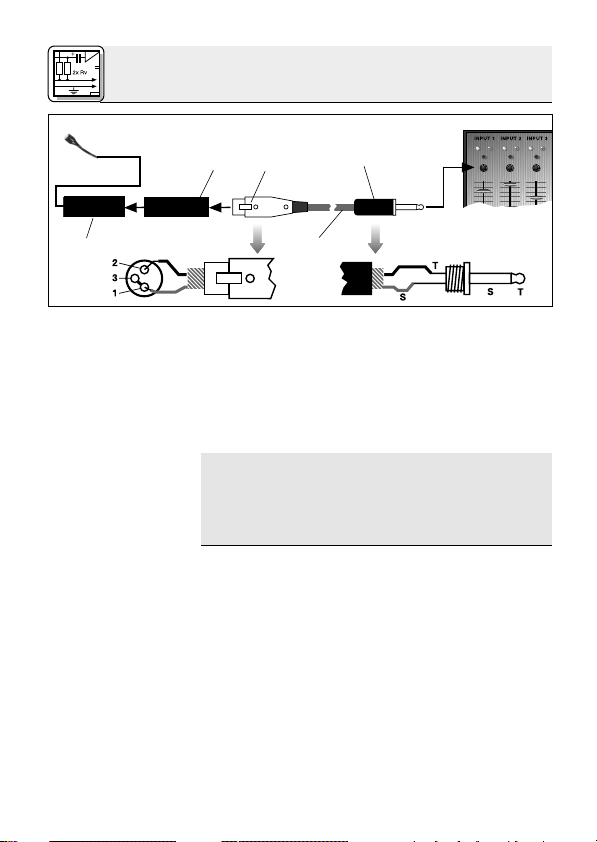
Siehe Abb. 1.
1. Stecken Sie den Phantomspeiseadapter (1) am
Mikrofonkabel an einen symmetrischen XLRMikrofoneingang mit Phantom speisung an.
2. Schalten Sie die Phantomspeisung ein. (Lesen
Sie dazu in der Betriebsanleitung des jeweiligen Gerätes nach.)
1
Phantom
2
XLR
Abb. 1: Anschluss an symmetrischen Eingang
3. Wenn Ihr Mischpult keine Phantom -
speisung besitzt, stecken Sie den
Phantomspeiseadapter (1) an ein optionales
AKG-Phantom speise gerät (2) (N 62 E, N 66 E,
B 18, B 15) an und verbinden Sie das
Phantomspeisegerät mit Hilfe eines XLRKabels (3) (z.B. AKG MK 9/10 - nicht mitgeliefert) mit einem symmetrischen Eingang.
XLR
1
3
4
Page 5

2 Anschluss
Phantomspeisegeräte (2) von AKG können Sie auch
an einen asymmetrischen Eingang an schließen.
Verwenden Sie dazu ein Kabel (3) mit XLRStecker (weiblich) und Mono-Klinkenstecker:
5
3
1
XLR
Phantom
4
2
Abb. 2: Anschluss an asymmetrischen Eingang
1. Verbinden Sie im XLR-Stecker (4) mittels einer
Drahtbrücke Stift 1 mit Stift 3 und mit der
Abschirmung.
2. Verbinden Sie die innere Ader des Kabels mit
Stift 2 des XLR-Steckers (4) und der Spitze
des Klinkensteckers (5).
Beachten Sie, dass asymmetrische Kabel Einstreuungen aus Magnetfeldern (von Netz- und
Lichtkabeln, Elektromotoren usw.) wie eine Antenne aufnehmen können . Bei Kabeln, die länger als 5 m sind, kann dies zu Brumm- und
ähnlichen Störgeräuschen führen.
Mit dem optionalen Batteriespeisegerät B 29 L
können Sie das Mikrofon an symmetrische oder
asymmetrische Eingänge ohne Phantomspeisung
anschliessen.
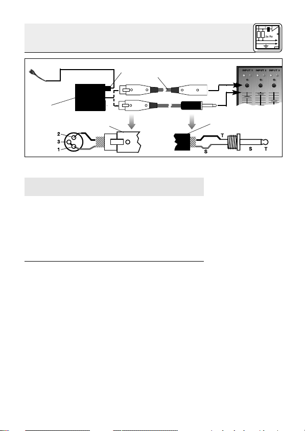
1. Stecken Sie den Mini-XLR-Stecker (1) am
Mikrofonkabel bis zum Anschlag in eine der
beiden Mini-XLR-Buchsen am B 29 L (2).
Der Stecker (1) verriegelt sich automatisch.
2.2.2 Anschluss
an asymmetrische Eingänge
Siehe Abb. 2.
Hinweis:
2.3 C 417
III
L/PL
2.3.1 Anschluss
mittels B 29 L
Siehe Abb.3.
Kabel anstecken:
5
Page 6
2 Anschluss
Kabel abziehen:
Wichtig!
2
Abb. 3: Anschluss-Schema mit B 29 L
Siehe Abb. 3.
Symmetrischer
Asymmetrischer
2.3.2 Anschluss
mittels MPA III L
Siehe Abb. 4.
Kabel abziehen:
6
B 29 L
Eingang:
Eingang:
Zum Abziehen des Kabels drücken Sie auf
den Entriegelungsknopf am Mini XLR-Stecker
(1) und ziehen Sie den Stecker (1) aus der
Buchse heraus.
Um das Kabel nicht zu beschädigen, ziehen Sie niemals am Kabel selbst!
1
3
4
2. Verbinden Sie das B 29 L (2) mit dem
gewünschten Eingang.
• Zum Anschluss an einen symmetrischen
Eingang verwenden Sie ein handelsübliches XLR-Kabel (3).
• Siehe Kapitel 2.2.2.
1. Stecken Sie den Mini-XLR-Stecker (1) am
Mikrofonkabel bis zum Anschlag in die MiniXLR-Kupplung (2) am Anschlusskabel des
MPA III L (3).
Der Stecker (1) verriegelt sich automatisch.
Siehe Kapitel 2.3.1.
2. Stecken Sie den MPA III L (3) an einen symmetrischen XLR-Mikrofoneingang mit Phan tomspeisung an.
3. Schalten Sie die Phantomspeisung ein. (Lesen
Sie dazu in der Betriebsanleitung des jeweiligen Gerätes nach.)
5
Page 7
Mini XLR Mini XLR MPA
1
MPA
Phantom
3
4
Abb. 4: Anschluss-Schema mit MPA III L
2 Anschluss
2
5
3
4. Wenn Ihr Mischpult keine Phantom speisung besitzt, stecken Sie den MPA III L
(3) an ein optionales AKG-Phantom speise gerät (4) (N 62 E, N 66 E, B 18, B 15) an und
verbinden Sie das Phantomspeisegerät (4) mit
Hilfe eines XLR-Kabels (5) (z.B. AKG MK 9/10
- nicht mitgeliefert) mit einem symmetrischen
Eingang.
Lesen Sie in der Bedienungsanleitung Ihres
Taschensenders nach.
Siehe Abb. 4.
2.3.3 Anschluss an
Taschensender
7
Page 8
3 Anwendung
3.1 Einleitung
3.2 Anwendung
als Lavalier -
mikrofon
Abb. 5: Mikrofon
an Ansteckclip (a)
und Anstecknadel
(b) befestigen
Abb. 6: Mikrofon
nahe beim Mund
befestigen
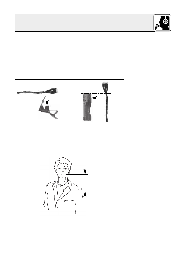
Der große Vorteil eines an der Kleidung oder in der
Maske befestigten Mikrofons besteht darin, dass
der Abstand zwischen dem Mikrofon und dem
Mund der Anwenderin/des Anwenders unabhängig von deren/dessen Bewegungen immer gleich
bleibt und damit keine Pegelschwankungen zu
befürchten sind. Die Bewegungsfreiheit bleibt erhalten, die Hände bleiben frei.
a b
1. Klemmen Sie das Kabel unmittelbar hinter dem
Mikrofongehäuse in eine der Aufnahmerillen
des mitgelieferten Ansteckclips H 40/1 (Abb.
5a) bzw. der mitgelieferten Anstecknadel H 41
(Abb. 5b).
min.
2. Befestigen Sie das Mikrofon so nahe wie möglich beim Mund der Rednerin/des Redners an
8
Page 9
der Kleidung, z.B. am Revers.
3 Anwendung
Je geringer der Abstand zwischen dem Mikrofon und der Schallquelle, umso geringer ist die
Gefahr akustischer Rückkopplungen.
1. Klemmen Sie das Kabel unmittelbar hinter dem
Mikrofongehäuse in die entsprechende Aufnahme des mitgelieferten Ansteckclips H 40/1
(Abb. 5a) bzw. der mitgelieferten Anstecknadel
H 41 (Abb. 5b).
2. Befestigen Sie das Mikrofon an einem geeigneten Dekorationsteil (z.B. Kulisse, Hintergrund, Vorhang o.ä.).
Befestigen Sie das Mikrofon in der Maske möglichst nahe beim Mund.
Abb. 7 zeigt eine Möglichkeit der Positionierung.
Je nach den Erfordernissen der Inszenierung können Sie das Mikrofon z.B. auch an der Stirn anbringen.
Hinweis:
3.3 Anwendung
als Aufnahmeoder
Stützmikrofon
3.4 Theater,
Musical, Oper
Abb. 7: Mikrofon in
der Maske
integriert
9
Page 10

3 Anwendung
3.5 Violine
Abb. 8: Abnahme
der Violine
10
Siehe Abb. 8.
4 Reinigung
Falls das Mikrofon nicht an der Violine selbst befestigt werden kann oder darf, können Sie das Mikrofon mit Mastix an der Wange der Geigerin/
des Geigers befestigen.
Diese Methode hat folgende Vorteile:
• Das Mikrofon ist nicht an der Violine selbst befestigt, daher wird der Klang der Violine nicht
beeinflusst.
• Es besteht keine Gefahr, die Violine durch Klebeband o.ä. zu beschädigen.
• Die Violine benötigt keinerlei lästige Kabelverbindung.
Reinigen Sie das Gehäuse des Mikrofons mit einem mit Wasser befeuchteten Tuch.
Page 11
5 Fehlerbehebung
Fehler
Kein Ton:
Verzerrungen:
Mögliche Ursache
1. Mischpult und/oder
Verstärker ausgeschaltet.
2. Kanal-Fader oder
Summenpegelregler
am Mischpult oder
Lautstärkeregler des
Verstärkers steht auf
Null.
3. Mikrofon nicht an
Mischpult oder
Verstärker angeschlossen.
4. Kabelstecker nicht
richtig angesteckt.
5. Kabel defekt.
6. Keine Speise spannung.
1. Gain-Regler am
Mischpult zu weit
aufgedreht.
2. Mischpulteingang zu
empfindlich.
Abhilfe
1. Mischpult und/oder
Verstärker ein schalten.
2. Kanal-Fader oder
Summenpegelregler
am Mischpult oder
Lautstärkeregler des
Verstärkers auf gewünschten Pegel
ein stellen.
3. Mikrofon an Mischpult oder Verstärker
an schließen.
4. Kabelstecker
nochmals anstecken.
5. Kabel überprüfen
und falls nötig er setzen.
6. Phantomspeisung
einschalten.
Phantomspeisegerät: ans Netz
anschließen bzw.
Batterie(n) einlegen.
Kabel überprüfen
und falls nötig er setzen.
1. Gain-Regler zurückdrehen.
2. 10-dB-Vorabschwächung
zwischen Mikrofonkabel und Eingang
stecken.
11
Page 12

6 Technische Daten
Arbeitsweise: Kondensatormikrofon mit
Permanentladung
Richtcharakteristik: Kugel
Übertragungsbereich: 20 - 20.000 Hz
Empfindlichkeit: 10 mV/Pa (-40 dBV bez. auf 1 V/Pa)
Elektrische Impedanz bei 1000 Hz: 200
Empfohlene Lastimpedanz: 2000
Grenzschalldruckpegel für 1% / 3% Klirrfaktor: 118 / 126 dB SPL
Äquivalentschalldruckpegel: 34 dB (nach IEC 60268-4)
III
Speisespannung: C 417
PP: 9-52 V Universalphantomspeisung
III
C 417
L/PL:
Batteriespeisegerät B 29 L,
Phantomspeiseadapter
oder AKG WMS Taschensender
MPA III L
Stromaufnahme: ca. 2,2 mA
III
Kabellänge/Steckerart: C 417
PP: 3 m / XLR 3-polig
III
C 417
L/PL: 1,5 m / Mini-XLR 3-polig
Oberfläche: mattschwarz (PP, L) oder pink (PL)
Abmessungen: 7,5 Ø x 15 mm
III
Gewicht netto (ohne Kabel)/brutto: C 417
C 417
III
PP: 8 g / 220 g
L/PL: 8 g / 160 g
Dieses Produkt entspricht den in der Konformitätserklärung angegebenen
Normen. Sie können die Konformitätserklärung auf http://www.akg.com oder
per E-Mail an sales@akg.com anfordern.
Frequenzgang Polardiagramm
12
Page 13

1 Precaution/Description
Please make sure that the piece of equipment
your microphone will be connected to fulfills the
safety regulations in force in your country and is
fitted with a ground lead.
1 C 417
III
1 W 407 1 H 40/1 1 H 41
Check that the packaging contains all of the components listed above. Should anything be miss ing, please contact your AKG dealer.
• MK 9/10 microphone cable: 10-m
(30-ft.) 2-conductor shielded cable
w/male and female XLR connectors
• MPA III L phantom power adapter
• B 29 L, B 15 battery power
supplies
• N 62 E, N 66 E,
B 18 phantom
power suppplies
1.1 Precaution
1.2 Unpacking
1.3 Optional
Accessories
• Professional miniature clip-on microphone.
• Omnidirectional condenser transducer for nat ural sound.
• Extended frequency response for clear reproduction of speech, vocals, violin.
1.4 Features
13
Page 14

1 Description
1.5 Brief
Description
1.6 Versions
III
C 417
C 417
C 417
PP:
III
L:
III
PL:
• Fastens on clothing or directly on the user's
head.
The C 417
III
is a professional miniature condenser
clip-on microphone with an omnidirectional polar
pattern. With its wide frequency range extending
from 20 Hz to 20 kHz, low distortion at high sound
pressure levels, small size, and useful accessories, the C 417
III
is an ideal choice for use in any sit uation requiring an inconspicuous microphone
and maximum mobility for the user.
The microphone is available in two different colors
and will almost disappear when blended in with an
actor's or singer's makeup.
An external windscreen supplied with the microphone reduces wind noise when using the microphone on an open-air stage.
The C 417
III
is available in three versions:
• With 3-pin XLR connector with integrated ad-
apter for 9 to 52 V universal phantom power.
• With locking mini XLR connector for use with
the B 29 L battery power supply, MPA III L
phantom power adapter, or AKG bodypack
transmitters.
• Identical to the C 417
III
L, except with flesh-
color cable and microphone body.
14
Page 15

The C 417
III
is a condenser microphone and there-
fore needs a power supply.
2 Interfacing
2.1 Introduction
Using any power supply other than those
recommended by AKG may damage your
microphone and will void the warranty.
1. Connect the phantom power adapter (1) on the
microphone cable to a balanced XLR microphone input with phantom power.
2. Switch the phantom power on. (Refer to the instruction manual of the unit to which you
connected your microphone.)
XLR
1
Phantom
2
1
3
Fig. 1: Connecting to a balanced input.
3. If your mixer provides no phantom power:
Connect the phantom power adapter (1) to an
optional AKG phantom power supply (2) (N 62 E,
N 66 E, B 18, B 15) and use an XLR cable (3)
(e.g., an optional MK 9/10 from AKG) to connect
the phantom power supply to the desired balanc ed input.
You may connect any AKG phantom power supply (2) to an unbalanced input, too.
Use a cable (3) with a female XLR connector and
TS jack plug:
Important!
2.2 C 417
2.2.1 Connecting
to Balanced
Inputs
Refer to fig. 1.
XLR
Refer to fig. 1.
2.2.2 Connecting
to Unbalanced
Inputs
Refer to fig. 2.
III
PP
15
Page 16
2 Interfacing
4
2
XLR
1
Phantom
3
Fig. 2: Connecting to an unbalanced input.
1. On the XLR connector (4), add a wire bridge to
connect pin 1 to pin 3 and the cable shield.
2. Connect the inside wire of the cable to pin 2
on the XLR connector (4) and the tip contact
of the jack plug (5).
Note:
Unbalanced cables may pick up interference
from stray magnetic fields near power or lighting
cables, electric motors, etc. like an antenna.
This may introduce hum or similar noise when
you use a cable that is longer than 16 feet (5 m).
2.3 C 417
2.3.1 Using the
Optional B 29 L
III
L/PL
The optional B 29 L battery supply allows you to
connect the microphone to balanced or un balanced inputs with no phantom power.
Refer to fig. 3.
Connecting the
cable:
1. Push the mini XLR connector (1) on the microphone cable into one of the two mini XLR
sockets on the B 29 L (2) to the stop.
The connector will lock automatically.
Disconnecting
the cable:
To disconnect the cable, press the unlocking
button on the mini XLR connector (1) and pull
the connector (1) out of the socket.
5
16
Page 17
2 Interfacing
1
3
2
Fig. 3: Using the B 29 L to power the microphone.
To avoid damaging the cable, never try to
pull out the cable itself!
2. Connect the B 29 L (2) to the desired input.
• Use a commercial XLR cable (3) to connect
• Refer to section 2.2.2 above.
1. Push the mini XLR connector (1) on the microphone cable into the mini XLR socket (2) on the
cable of the MPA III L (3) to the stop.
The connector will lock automatically.
Refer to section 2.3.1 above.
2. Connect the MPA III L (3) to a balanced XLR
microphone input with phantom power.
3. Switch the phantom power on. (Refer to the instruction manual of the unit to which you
connected your microphone.)
B 29 L
4
the B 29 L (2) to a balanced input.
5
Important!
Refer to fig. 3.
Balanced input:
Unbalanced input:
2.3.2 Using the
MPA III L
Refer to fig. 4.
Disconnecting
the cable:
17
Page 18

2 Interfacing
Mini XLR Mini XLR MPA
1
MPA
Fig. 4: Connection diagram with MPA III L.
Phantom
3
4
2
3
5
Refer to fig. 4.
2.3.3 Connecting
to a Bodypack
Transmitter
18
4. If your mixer provides no phantom power:
Connect the MPA III L (3) to an optional AKG
phantom power supply (4) (N 62 E, N 66 E, B 18,
B 15) and use an XLR cable (5) (e.g., an optional
MK 9/10 from AKG) to connect the phantom
power supply (4) to the desired balanc ed input.
Refer to the manual of your bodypack transmitter.
Page 19
3 Using Your Microphone
The principal benefit of a microphone attached to
the user's clothes or integrated in their makeup is
that the microphone will maintain a constant
work ing distance independently of the user's move ments and thus ensure a constant output lev el.
Also, a clip-on microphone allows the user to
move about freely and keeps their hands free.
a b
1. Insert the cable into one of the fixing grooves
on the supplied H 40/1 clip (se fig. 5a) or on the
supplied H 41 tie pin (see fig. 5b), at a point immediately behind the microphone body.
min.
3.1 Introduction
3.2 Lavalier
Miking
Fig. 5: Fixing the
microphone on the
clip (a) or tie pin (b).
Fig. 6: Attaching
the microphone
near the user's
mouth.
2. Attach the microphone to the talker's clothes,
e.g., on the lapel, placing it as close as possible to the talker's mouth.
19
Page 20

3 Using Your Microphone
Note:
3.3 Live
Recording and
Spot Miking
3.4 Theater,
Musical, Opera
Fig. 7: Microphone
integrated in per-
former's makeup.
The smaller the distance between the microphone and the sound source, the higher the
usable gain before feedback.
1. Insert the cable into one of the fixing grooves
on the supplied H 40/1 clip (se fig. 5a) or on the
supplied H 41 tie pin (see fig. 5b).
2. Fix the microphone on a suitable part of the
stage decoration such as a flat, backdrop, curtain, etc.
Fix the microphone on the user's head, as close
as possible to the mouth, and blend it in with the
makeup.
Many engineers place the microphone as shown
in fig. 7.
Depending on the requirements of the production
at hand, you may also attach the microphone in
different places, e.g., on the performer's forehead.
20
Page 21

3 Using Your Microphone
3.5 Violin
Fig. 8: Miking up a
violin.
If the production concept does not allow for
microphones mounted on the the violin itself, you
can attach the microphone with mastic to the violin ist's cheek.
This method provides the following benefits:
• Since the microphone is not mounted on the
violin itself, it will not affect the sound of the instrument.
• There will be no risk of damaging the violin with
adhesive tape or similar mounting materials.
• There will be no cable that gets in the way.
4 Cleaning
To clean the microphone case, use a soft cloth
moistened with water.
Refer to fig. 8.
21
Page 22

5 Troubleshooting
Problem
No sound:
Distortion:
Possible Cause
1. Power to mixer
and/or amplifier is
off.
2. Channel or master
fader on mixer, or
volume control on
amplifier is at zero.
3. Microphone is not
connected to mix er or amplifier.
4. Cable connectors
are seated loosely.
5. Cable is defective.
6. No supply voltage.
1. Gain control on
the mixer set too
high.
2. Mixer input sensitivity too high.
Remedy
1. Switch power to
mixer or amplifier
on.
2. Set channel or
master fader on
mixer or volume
control on amplifier to desired
lev el.
3. Connect microphone to mixer or
amplifier.
4. Check cable
connectors for secure seat.
5.
Check cable and replace if damaged.
6. Switch phantom
power on.
Phantom power
supply: connect to
power outlet or insert battery
(batteries).
Check cable and replace if necessary.
1. Turn gain control
down CCW.
2. Connect a 10-dB
preattenuation
pad between
microphone cable
and input.
22
Page 23

6 Specifications
Type: pre-polarized condenser microphone
Polar pattern: omnidirectional
Frequency range: 20 Hz to 20,000 Hz
Sensitivity at 1 kHz: 10 mV/Pa (-40 dBV re 1 V/Pa)
Impedance: 200
Recommended load impedance: 2000
Max. SPL for 1%/3% THD: 118/126 dB SPL
Equivalent noise level: 34 dB (A) (to IEC 60268-4)
Power requirement:
Current consumption: approx. 2.2 mA
Cable length/Connector: C 417
Finish: matte black (PP, L) or flesh-color (PL)
Size: 7.5 x 15 mm (0.3 x 0.6 in.)
Net/shipping weight: C 417
This product conforms to the standards listed in the Declaration of Conformity.
To order a free copy of the Declaration of Conformity, visit http://www.akg.com
or contact sales@akg.com.
Frequency Response Polar Diagram
III
C 417
PP: 9 to 52 V universal phantom power
III
L/PL: B 29 L battery power supply,
C 417
C 417
C 417
MPA III L phantom adapter, or
AKG WMS bodypack transmitters
III
PP: 3 m (10 ft.) / 3-pin male XLR
III
L
/PL
: 1.5 m (5 ft.) / 3-pin mini XLR
III
PP: 8 g (0.3 oz.) / 220 g (7.8 oz.)
III
L
/PL
: 8 g (0.3 oz.) / 160 g (5.6 oz.)
23
Page 24

1 Consigne de sécurité / Description
1.1 Consigne de
sécurité
1.2 Fournitures
1.3 Accessoires
optionnels
Vérifiez si l’appareil auquel vous voulez raccorder
le microphone répond aux prescriptions relatives
à la sécurité en vigueur et s’il possède une mise à
la terre de sécurité.
1 C 417
III
1 W 407 1 H 40/1 1 H 41
Contrôlez si le carton contient bien tous les éléments énumérés ci-dessus. Si ce n’est pas le cas,
veuillez contacter votre distributeur AKG.
•
Câble de micro MK 9/10 : câble blindé
bipolaire de 10 m, avec connecteurs
XLR mâle et femelle
• Adaptateur pour alimentation
fantôme MPA III L
• Alimentations à piles
B 29 L, B 15
•
Appareils d’alimenta-
tion fantôme
N 62 E,
N 66 E, B 18
Caractéristiques
1.4
particulières
24
• Micro-cravate miniature professionnel.
• Transducteur électrostatique à champ uniforme pour l’obtention d’un son naturel.
• Réponse en fréquence étendue, pour la voix, le
chant, le violon.
Page 25

1 Description
• Se fixe aux vêtements ou directement sur le visage de l’utilisateur.
Le C 417
miniature omnidirectionnel. Grâce à sa réponse en
fréquence s’étendant de 20 à 20.000 Hz et aux faibles distorsions même pour une pression acoustique élevée, grâce aussi à sa petite taille et à ses
accessoires universels, ce microphone professionnel est idéal pour toutes les applications exigeant une technique du micro discrète et une
grande liberté de mouvements de l’utilisateur.
Il est proposé en deux coloris permettant de l’intégrer de façon presque invisible au maquillage des
acteurs ou des chanteurs.
Une bonnette antivent externe atténuant les bruits
de vent pour l’utilisation en plein air est fournie
avec le micro.
Le C 417
• Avec connecteur type XLR à trois points, avec
• Avec connecteur type XLR miniature, verrouilla-
• Comme C417
III
est un micro-cravate électrostatique
III
existe en trois versions :
adaptateur incorporé pour alimentation
fantôme universelle de 9 à 52 V.
ble, pour raccordement à une alimentation à piles
B 29 L, à un adaptateur pour alimentation fantôme
MPA III L ou à un émetteur de poche AKG.
III
L, câble et micro roses.
1.5 Description
1.6 Versions
III
C 417
C 417
C 417
PP
III
L
III
PL
25
Page 26

2 Raccordement
2.1 Introduction
Le C 418
III
PP/C 418
III
L est un microphone élec-
trostatique ; il a donc besoin d’une alimentation.
Important!
L’utilisation d’alimentations autres que celles recommandées par AKG peut provoquer
des dégâts sur le micro et entraîne la perte
de la garantie.
2.2 C 417
Raccordement
sur une entrée
III
PP
2.2.1
symétrique
Voir Fig. 1.
1. Connectez l’adaptateur pour alimentation
fantôme du câble micro sur une entrée de
micro symétrique type XLR avec alimentation
fantôme.
2. Mettez l’alimentation fantôme sous tension
(Veuillez vous reporter à la notice de l’alimentation utilisée).
XLR
1
Phantom
2
1
3
Fig. 1 : Raccordement sur une entrée symétrique
3. Si vous n’avez pas d’alimentation
fantôme sur votre table de mixage, branchez l’adaptateur pour alimentation fantôme
(1) sur une alimentation fantôme AKG optionnelle (2) (N 62 E, N 66 E, B 18, B 15) et raccordez l’alimentation fantôme à une entrée
symétrique à l’aide d’un câble XLR (3) (p.ex.
AKG MK 9/10 – n’est pas fourni avec le micro).
XLR
26
Page 27

2 Raccordement
Vous pouvez aussi connecter les alimentations fantôme
d’AKG (2) sur une entrée asymétrique.
Il vous faut un câble (3) avec une fiche XLR femelle
et une fiche à jack mono:
5
3
1
XLR
Phantom
4
2
2.2.2
Raccordement
sur une entrée
asymétrique
Fig. 2 : Raccordement sur une entrée asymétrique
1. Pontez les contacts 1 et 3 de la fiche XLR (4) et
Voir Fig. 2.
reliez-les au blindage du câble.
2. Reliez le conducteur interne du câble au
contact 2 de la fiche XLR (4) et à la pointe de la
fiche à jack (5).
Les câbles asymétriques peuvent capter
N.B.
comme une antenne les interférences de
champs magnétiques (câbles lumière ou force,
moteurs électriques, etc.). Si le câble mesure
plus de 5 m ce phénomène pourra se traduire
par des ronflements et autres parasites.
L’alimentation à pile B 29 L optionnelle vous permet de raccorder le micro à des entrées symétriques ou asymétriques sans alimentation fantôme.
2.3 C 417
2.3.1 Raccorde ment au moyen
du B 29 L
1. Enfoncez le connecteur mini-XLR (1) du câble
du micro à fond dans une des deux embases
mini-XLR du B 29 L (2).
Voir Fig. 3.
Brancher le
câble:
Le connecteur (1) se verrouille automatiquement.
III
L/PL
27
Page 28

2 Raccordement
Débrancher le
câble :
Important !
2
Fig. 3 : Schéma de raccordement avec B 29 L
Entrée symétrique:
Entrée asymétrique:
Raccordement
avec MPA III L
Débrancher le
28
B 29 L
Cf. Fig. 3.
2.3.2
Voir Fig. 4.
câble :
Pour détacher le câble, appuyez sur le bouton
de déverrouillage du connecteur mini-XLR (1)
et sortez le connecteur de la prise.
Pour ne pas risquer d’abîmer le câble, ne
sortez jamais le connecteur en tirant sur
le câble.
1
3
4
2. Raccordez le B 29 L (2) sur l’entrée voulue.
• Pour le raccordement sur une entrée symétrique, utilisez un câble XLR (3) en vente
dans le commerce.
• Voir point 2.2.2.
1. Enfoncez le connecteur mini-XLR (1) du câble
micro jusqu’en butée dans l’accouplement
mini-XLR (2) du câble de raccordement du
MPA III L (3).
Le connecteur (1) se verrouille automatiquement.
Voir point 2.3.1.
2. Connectez le MPA III L (3) sur une entrée de
micro symétrique type XLR avec alimentation
fantôme.
3. Mettez l’alimentation fantôme sous tension
(Veuillez vous reporter à la notice de l’alimentation utilisée).
5
Page 29

2 Raccordement
Mini XLR Mini XLR MPA
1
MPA
Phantom
3
4
Fig. 4: Schéma de raccordement avec MPA III L
2
5
3
4. Si vous n’avez pas d’alimentation
fantôme sur votre table de mixage, bran-
chez le MPA III L (3) sur une alimentation
fantôme AKG optionnelle (4) (N 62 E, N 66 E, B
18, B 15) et raccordez l’alimentation fantôme à
une entrée symétrique à l’aide d’un câble XLR
(5) (p.ex. AKG MK 9/10 – n’est pas fourni avec
le micro).
Conformez-vous aux instructions du mode d’emploi de votre émetteur de poche.
Voir Fig. 4.
2.3.3
Raccordement
sur un émetteur
de poche
29
Page 30

3 Utilisation
3.1 Introduction
3.2 Utilisation
en tant que
micro lavallière
Fig. 5 : Fixation du
micro au clip (a) et
à l’épingle (b)
Fig. 6 : Fixation du
micro près des
lèvres
Le gros avantage d’un micro pouvant être fixé aux
vêtements ou intégré dans le maquillage est le fait
que la distance du micro aux lèvres reste constante indépendamment des mouvements de la
personne qui l’utilise, ce qui permet d’éviter les
variations de niveau. L’utilisateur a les mains libres
et n’est pas gêné dans ses mouvements.
a b
1. Insérez le câble, immédiatement à la sortie du
boîtier, dans une des rainures du clip H 40/1
fourni (Fig. 5a) ou le l’épingle H 41 fournie
(Fig. 5b).
min.
2. Fixez le micro aux vêtements, p.ex. au revers
d’une veste, aussi près que possible des lèvres
de l’utilisateur.
30
Page 31

3 Utilisation
Moins le micro est éloigné de la source sonore,
moins il y a de risques de larsen.
1. Insérez le câble, immédiatement à la sortie du
boîtier, dans une des rainures du clip H 40/1
fourni (Fig. 5a) ou de l’épingle H 41 fournie
(Fig. 5b).
2. Fixez le micro à un élément du décor, panneau
de scène, rideau, etc.
Fixez le micro sur le visage, aussi près des lèvres
que possible.
On peut voir un exemple de positionnement à la
Fig. 7.
On pourra aussi, suivant la situation donnée, choisir un autre emplacement, p.ex. sur le front.
Remarque :
3.3 Utilisation
comme micro
d’enregistrement ou micro
de soutien
3.4 Théâtre,
musical, opéra
Fig. 7 : Microphone
intégré au
maquillage
31
Page 32

3 Utilisation
3.5 Violon
Fig. 8 : Prise du
4 Nettoyage
32
violon
Cf. Fig. 8
S’il n’est pas possible de fixer le micro directement sur le violon, on pourra le coller à l’aide de
mastic sur la joue du ou de la violoniste.
Cette méthode présente les avantages suivants :
• Le micro n’étant pas fixé directement sur le
violon il n’a aucune influence sur la sonorité de
l’instrument.
• On ne risque pas d’abîmer le violon, p.ex. en
collant un ruban adhésif.
• Le violon n’est pas relié à un câble.
Le boîtier du micro se nettoie avec un chiffon
légèrement humide (eau claire).
Page 33

5 Dépannage
Problème
Pas de son :
Distorisons :
Cause possible
1. La console de mixage
et/ou l’amplificateur ne
sont pas sous tension.
2. Le fader du canal ou le
réglage de niveau master de la console de
mixage ou le réglage
de niveau sonore de
l’ampli est sur zéro.
3. Le micro n’est pas
connecté à la console
de mixage ou à l’ampli.
4. La fiche est mal enfoncée.
5. Le câble est abîmé.
6. Pas de tension d’alimentation.
1. Le réglage de gain de
la table de mixage est
trop haut.
2. L’entrée de la table de
mixage est trop sensible.
Remède
1. Mettre la console de
mixage et/ou l’amplificateur sous tension.
2. Régler le fader du canal ou le réglage de niveau master de la console de mixage ou le
réglage de niveau sonore de l’ampli sur la
valeur voulue.
3. Connecter le micro à la
console de mixage ou
à l’ampli.
4. Enfoncer la fiche correctement.
5. Contrôler le câble et le
remplacer le cas
échéant.
6. Mettre l’alimentation
fantôme sous tension.
Appareil d’alimentation
fantôme : brancher sur
le secteur ou mettre
une (des) pile(s).
Contrôler le câble et le
remplacer le cas
échéant.
1. Baisser le réglage de
gain.
2. Insérer un pré-atténuateur de sensibilité entre
le câble du micro et
l’entrée.
33
Page 34

6 Caractéristiques techniques
Fonctionnement: microphone électrostatique à charge per-
manente
Directivité: omnidirectionnel
Réponse en fréquence: 20 … 20.000 Hz
Sensibilité : 10 mV/Pa (-40 dBV rapp. à 1 V/Pa)
Impédance électrique à 1.000 Hz: 200
Impédance de charge recommandée: 2000
Niveau maximum de pression sonore pour un facteur
de distorsion de 1% / 3%: 118 / 126 dB SPL
Niveau de bruit équivalent: 34 dB (A) (selon )
Tension d’alimentation: C 417
C 417
III
III
IEC 60268-4
PP: 9 … 52 V, al. fantôme universelle
L/PL: alimentation à piles B 29 L,
adaptateur fantôme MPA III L ou
émetteurs de poche AKG WMS
Consommation: env. 2,2 mA
III
Connecteur: C 417
PP: 3 m / type XLR, 3 points
III
C 417
L/PL: 1,5 m / type mini-XLR, 3 points
Couleur: noir mat (PP, L) ou rose (PL)
Dimensions: 7,5 x 15 mm
III
Poids net/brut : C 417
PP: 8 g /220 g
III
C 417
L/PL: 8 g / 160 g
Ce produit est conforme aux normes citées dans la Déclaration de Conformité,
dont vous pouvez prendre connaissance en consultant le site
http://www.akg.com ou en adressant un e-mail à sales@akg.com.
Réponse en fréquence Diagramme polaire
34
Page 35

1 Indicazione per la sicurezza / Descrizione
Controllate per favore se l’apparecchio che volete
collegare al microfono corrisponde alle norme di
sicurezza vigenti e se è dotato di una messa a
terra di sicurezza.
1 C 417
III
1 W 407 1 H 40/1 1 H 41
Controllate per favore se la confezione contiene
tutti i componenti di cui sopra. Se manca qualcosa rivolgetevi al vostro rivenditore AKG.
• Cavo microfonico MK 9/10: cavo lungo
10 m, schermato, a 2 poli, con connet-
tore XLR e accoppiamento XLR.
• Adattatore phantom MPA III L
• Alimentatori a batteria
B 29 L, B 15
• Alimentatori
phantom N 62 E,
N 66 E, B 18
1.1 Indicazione
per la sicurezza
1.2 In dotazione
1.3 Accessori
raccomandati
• Microfono professionale miniaturizzato a clip.
• Trasduttore a condensatore dalla direttività omnidirezionale per ottenere un suono naturale.
• Vasta gamma di trasmissione per lingua parlata, canto, violino.
1.4
Caratteristiche
particolari
35
Page 36

1 Descrizione
1.5 Breve
descrizione
1.6 Varianti
III
C 417
C 417
C 417
PP
III
L
III
PL
• Adatto per essere fissato sull’abbigliamento o
direttamente sulla testa dell’utente.
III
Il C 417
è un professionale microfono miniaturizzato a condensatore a clip dalla direttività omnidirezionale. Grazie alla vasta gamma di trasmissione dai 20 fino ai 20.000 Hz, alle poche distorsioni in caso di forti pressioni acustiche nonché
alle piccole dimensioni e agli accessori dall’impiego universale, il microfono è ideale per tutte
quelle applicazioni in cui si rendono necessarie
tecnica microfonica poco vistosa e grande libertà
di movimento per gli utenti.
Due colori differenti permettono l’integrazione
quasi invisibile del microfono nei costumi di cantanti ed attori.
Un’antisoffio esterno per l’attenuazione dei rumori
prodotti dal vento durante gli impieghi all’aperto è
in dotazione.
III
Il C 417
è disponibile in tre varianti:
• Con connettore XLR a 3 poli con adattatore in-
corporato per l’alimentazione phantom universale da 9 a 52 V.
• Con connettore mini-XLR arrestabile per il col-
legamento all’alimentatore a batteria B 29 L,
all’adattatore per l’alimentazione phantom
MPA III L o ai trasmettitori da tasca AKG.
• Come il C 417
III
L, cavo e testa microfonica in
pink.
36
Page 37

Il C 417
III
è un microfono a condensatore e ha
quindi bisogno di alimentazione.
2 Collegamento
2.1 Introduzione
Se usate alimentatori diversi da quelli raccomandati dall’AKG, il microfono può subire danni e la garanzia si estingue.
1. Collegate l’adattatore per l’alimentazione
phantom disposto sul cavo microfonico a un
ingresso microfonico XLR simmetrico con alimentazione phantom.
2. Inserite l’alimentazione phantom. (Leggete in
merito le istruzioni per l’uso del rispettivo apparecchio.)
XLR
1
Phantom
2
1
3
Fig. 1: Collegamento ad un ingresso simmetrico
3. Se il vostro mixer non è dotato di alimen-
tazione phantom, inserite l’adattatore per alimentazione phantom (1) in un alimentatore
phantom AKG opzionale (2) (N 62 E, N 66 E,
B 18, B 15) e collegate l’alimentatore phantom
servendovi di un cavo XLR (3) (p.e. AKG
MK 9/10 – non in dotazione) ad un ingresso
simmetrico.
Importante!
2.2 C 417
2.2.1
Collegamento
ad ingressi
simmetrici
Vedi fig. 1.
XLR
III
PP
37
Page 38

2 Collegamento
2.2.2
Collegamento
ad ingressi
asimmetrici
Gli alimentatori phantom (2) dell’AKG possono venir collegato anche ad un ingresso asimmetrico.
Usate un cavo (3) con una presa XLR (4) e una
spina jack mono (5):
5
3
1
XLR
Phantom
4
2
Fig. 2: Collegamento ad un ingresso asimmetrico
Vedi fig. 2.
1. Nella presa XLR (4), collegate con un ponte a
filo i contatti 1 e 3 e portateli sullo schermo del
cavo.
2. Collegate il conduttore interno del cavo con il
contatto 2 della presa XLR (4) e la punta della
spina jack (5).
Nota:
Tenete presente che i cavi asimmetrici possono assorbire, come un’antenna, irradiazioni
da campi magnetici (cavi di rete, cavi della
luce, elettromotori ecc.). Nel caso di cavi la cui
lunghezza supera i 5 m, questo fenomeno può
causare ronzìi ed altri rumori disturbanti.
2.3 C 417
Collegamento
III
2.3.1
L/PL
Con l’alimentatore a batterie opzionale B 29 L potete collegare il microfono ad ingressi simmetrici o
asimmetrici senza alimentazione phantom.
con B 29 L
Inserire il cavo:
1. Inserite il connettore mini-XLR (1) sul cavo
microfonico in una delle due prese mini-XLR
Vedi fig. 3.
sul B 29 L (2) fino all’arresto.
38
Page 39

2 Collegamento
Il connettore (1) si blocca automaticamente.
Per sfilare il cavo, premete il bottone di sblocco
sul connettore mini-XLR (1) e sfilate il connettore (1) dalla presa.
Per non danneggiare il cavo, non esercitate mai trazione direttamente sul cavo!
1
3
2
Fig. 3: Schema di collegamento con B 29 L
2. Collegate il B 29 L (2) con l’ingresso prescelto.
• Per il collegamento ad un ingressso simme-
• Vedi capitolo 2.2.2.
1. Inserite il connettore mini-XLR (1) disposto sul
cavo microfonico fino all‘arresto
nell‘accoppiamento mini-XLR (2) disposto sul
cavo di collegamento dell’MPA III L (3).
Il connettore (1) si blocca automaticamente.
Vedi capitolo 2.3.1.
2. Collegate l’MPA III L (3) disposto sul cavo
microfonico a un ingresso microfonico XLR
simmetrico con alimentazione phantom.
3. Inserite l’alimentazione phantom. (Leggete in
merito le istruzioni per l’uso del rispettivo apparecchio.)
B 29 L
4
trico servitevi di un cavo XLR commerciale (3).
Sfilare il cavo:
Importante!
5
Vedi fig. 3.
Ingresso
simmetrico:
Ingresso
asimmetrico:
2.3.2
Collegamento
con MPA III L
Vedi fig. 4.
Sfilare il cavo:
39
Page 40

2 Collegamento
Mini XLR Mini XLR MPA
1
MPA
Phantom
3
4
Fig. 4: Schema di collegamento con MPA III L
2
3
5
Vedi fig. 4.
2.3.3
Collegamento
ad un trasmetti-
tore da tasca
40
4. Se il vostro mixer non è dotato di alimen-
tazione phantom, inserite l’MPA III L (3) in un
alimentatore phantom AKG opzionale (4) (N 62 E,
N 66 E, B 18, B 15) e collegate l’alimentatore
phantom (4) servendovi di un cavo XLR (5) (p.e.
AKG MK 9/10 – non in dotazione) ad un ingresso simmetrico.
Leggete al riguardo le istruzioni per l’uso del vostro trasmettitore da tasca.
Page 41

3 Impieghi
Il grande vantaggio di un microfono fissato
sull’abbigliamento o sul costume consiste nel
fatto che la distanza tra microfono e bocca dell’utente, indipendentemente dai suoi movimenti, rimane sempre invariata; non si devono quindi temere oscillazioni di livello, la libertà di movimento
non viene pregiudicata e le mani rimangono libere.
a b
1. Fissate il cavo inserendolo direttamente dietro
alla scatola microfonica in una delle scanalature del clip di fissaggio H 40/1 (fig. 5a) risp.
della spilla di fissaggio H 41 (fig. 5b), ambedue
in dotazione.
min.
3.1 Introduzione
3.2 Impiego
come microfono
lavalier
Fig. 5: Fissare il
microfono sul clip
di fissaggio (a) e
sulla spilla di fissaggio (b).
Fig. 6: Fissare il
microfono vicino
alla bocca
2. Fissate il microfono sull’abbigliamento, p.e. sul
risvolto della giacca, il più vicino possibile alla
bocca dell’oratore.
41
Page 42

3 Impieghi
Avvertenza:
3.3 Impiego
come microfono
di registrazione
o di rinforzo
3.4 Teatro,
musical, opera
Fig. 7: Microfono
integrato nel
costume
Più si riduce la distanza tra microfono e fonte
sonora, più si riduce il pericolo di feedback
acustici.
1. Fissate il cavo inserendolo direttamente dietro
alla scatola microfonica nella corrispondente
sede del clip di fissaggio H 40/1 (fig. 5a) risp.
della spilla di fissaggio H 41 (fig. 5b), ambedue
in dotazione.
2. Fissate il microfono su decorazioni adatte (p.e.
quinte, sfondi, tele o simili).
Fissate il microfono sul costume, il più vicino possibile alla bocca.
La fig. 7 dimostra un possibile posizionamento.
A seconda delle esigenze della messa in scena
potete fissare il microfono anche p.e. sulla fronte.
42
Page 43

3 Impieghi
3.5 Violino
Fig. 8: Ripresa del
violino
Se il microfono non può o non deve venir fissato
direttamente sul violino, potete fissarlo con l’aiuto
di mastice sulla guancia del violinista.
Questo metodo presenta i seguenti vantaggi:
• Il microfono non è fissato direttamente sul violino e non ne pregiudica quindi il suono.
• Non c’è pericolo di danneggiare il violino con
nastro adesivo o simile.
• Non c’è bisogno di collegamenti a cavo col
violino che potrebbero dar fastidio.
Pulite la scatola del microfono con un panno inumidito con acqua.
Vedi Fig. 8.
4 Pulizia
43
Page 44

5 Eliminazione di difetti
Difetto
Nessun suono:
Distorsioni:
Possibili cause
1. Mixer e/o amplificatore sono dis inseriti.
2. Fader del canale o regolatore principale
del mixer o regolatore
del volume dell’amplificatore sono in posizione zero.
3. Il microfono non è
collegato al mixer o
all’amplificatore.
4. Il connettore del cavo
non è inserito bene.
5. Il cavo è difettoso.
6. Non c’è alimentazione.
1. Il regolatore gain sul
mixer è aperto
troppo.
2. L’ingresso del mixer è
troppo sensibile.
Rimedio
1. Inserire il mixer e/o
l’amplificatore.
2. Portare al livello desiderato il fader del canale o il regolatore
principale del mixer o
il regolatore del volume dell’amplificatore.
3. Collegare il microfono
al mixer o all’amplificatore.
4. Inserire di nuovo il
connettore del cavo.
5. Controllare il cavo e
sostituirlo se necessario.
6. Inserire l’alimentazione phantom.
Alimentatore phantom: collegarlo alla
rete oppure inserire
batteria(e).
Controllare il cavo e,
se necessario, sostituirlo.
1. Portare indietro il regolatore gain.
2. Inserire un preattenuatore di 10 dB tra cavo
microfonico ed ingresso.
44
Page 45

6 Dati tecnici
Modo di funzionamento: microfono a condensatore con carica per-
manente
Direttività: omnidirezionale
Risposta in frequenza: 20 - 20.000 Hz
Sensibilità: 10 mV/Pa (-40 dBV rif. a 1 V/Pa)
Impedenza elettrica a 1000 Hz: 200
Impedenza di carico raccomandata: 2000
Livello di pressione acustica limite per un coefficiente di distorsione armonica
di 1% / 3%: 118 / 126 dB SPL
Livello di pressione acustica equivalente: 34 dB (secondo IEC 60268-4)
III
Tensione di alimentazione: C 417
PP: al. phantom universale 9 - 52 V
III
L/PL:
C 417
alimentatore a pila B 29 L, adattatore phantom MPA III L o trasmettitori da tasca AKG WMS
Assorbimento: 2,2 mA circa
III
Lunghezza del cavo / connettore: C 417
PP: 3 m / XLR a 3 poli
III
C 417
L/PL: 1,5 m / mini-XLR a 3 poli
Superficie: nero opaco (PP, L) o pink (PL)
Dimensioni: 7,5 x 15 mm
III
Peso netto/lordo: C 417
C 417
III
PP: 8 g / 220 g
L/PL: 8 g / 160 g
Questo prodotto corrisponde alle norme elencate nella dichiarazione di
conformità, che è disponibile al sito http://www.akg.com oppure all’indirizzo
email sales@akg.com.
Risposta in frequenza Diagramma polare
45
Page 46

1 Indicaciones de seguridad / Descripción
1.1 Indicaciones
de seguridad
1.2 Volumen de
suministro
1.3 Accesorios
opcionales
Sírvase verificar si el aparato al cual quiere conectar el micrófono cumple con las disposiciones de
seguridad vigentes y está equipado con una toma
de tierra de seguridad.
1 C 417
III
1 W 407 1 H 40/1 1 H 41
Sírvase controlar si el embalaje contiene todas las
piezas indicadas arriba. Si falta algo, le rogamos dirigirse a su distribuidor AKG.
• Cable de micrófono MK 9/10: 10 m
de cable bipolar apantallado con
conector y acoplamiento XLR.
• Adaptador de alimentación fantasma
MPA III L
• Alimentadores por batería
B 29 L, B 15
• Alimentadores
fantasma N 62 E,
N 66 E, B 18
Características
especiales
46
1.4
• Minimicrófono profesional con dispositivo para
abrochar
• Transductor de condensador con característica
direccional omnidireccional para la obtención de
un sonido natural.
Page 47

1 Descripción
• Amplia gama de frecuencia para habla, canto,
violín.
• Apto para ser fijado a la ropa o directamente en la
cabeza de la persona que lo utiliza.
III
El C 417
densador con característica direccional omnidireccional. Debido a su amplia gama de frecuencia de 20
a 20.000 Hz, las escasas distorsiones con alta intensidad acústica, sus pequeñas dimensiones y la aplicación universal de sus accesorios, es ideal para ser
utilizado en todos los casos en que el micrófono
debe pasar desapercibido y la persona que lo utiliza
necesita tener una gran libertad de movimiento.
Las dos variantes de color permiten integrar el
micrófono a la máscara de actores y cantantes de
modo tal que resulte prácticamente invisible.
En el suministro se incluye una pantalla antiviento
externa para amortiguar los ruidos del viento cuando
se utiliza el micrófono al aire libre.
El C 417
• Con conector XLR de 3 polos y con adaptador in-
• Con conector mini-XLR enclavable para la cone-
• Como C 417
es un minimicrófono profesional de con-
III
puede adquirirse en dos modelos:
corporado para alimentación fantasma universal
de 9 a 52 V.
xión al alimentador de batería B 29 L, al adaptador de alimentación fantasma MPA III L o un emisor de bolsillo AKG.
III
L, cable y cabeza de micrófono de
color rosa.
1.5 Breve
descripción
1.6 Variantes
III
C 417
C 417
C 417
PP
III
L
III
PL
47
Page 48

2 Conexión
2.1 Introducción
III
El C
417
es un micrófono de condensador y ne-
cesita, por lo tanto, alimentación de corriente.
¡Importante!
Si se utilizan alimentadores diferentes a
los recomendados por AKG puede dañarse
el micrófono, cesando con ello la garantía.
2.2 C
2.2.1 Conexión a
balanceadas
III
417
PP
entradas
Ver Fig. 1.
1. Conecte el adaptador de alimentación fantasma del cable del micrófono a una entrada
de micrófono XLR balanceada con alimentación fantasma.
2. Concecte la alimentación fantasma (consulte
para ello el Modo de empleo del aparato correspondiente).
1
Phantom
2
XLR
Fig. 1: Conexión a entrada balanceada
3. Si su pupitre de mezclas no tiene ali-
mentación fantasma, enchufe el adaptador
de alimentación fantasma (1) al alimentador de
tensión fantasma de AKG opcional (2) (N 62 E,
N 66 E, B 18, B 15) y conecte luego el alimentador de tensión fantasma a una entrada balanceada utilizando un cable XLR (3) (por ej.:
AKG MK 9/10 - no incluido en el suministro).
XLR
1
3
48
Page 49

2 Conexión
Los alimentadores fantasma (2) de AKG pueden
conectarse también a una entrada no balanceada.
Use un cable (3) con una hembra de conector XLR
y un conector jack mono:
5
3
1
XLR
Phantom
4
2
Fig. 2: Conexión a una entrada no balanceada.
1. Una mediante un puente de alambre la espiga 1
del conector XLR (4) con la espiga 3 y con la
pantalla del cable.
2. Una el conductor interno del cable con la
espiga 2 del conector XLR (4) y la punta del
conector jack (5).
Los cables no balanceados pueden recoger interferencias de campos magnéticos (de los cables de red, de alumbrado, de motores eléctricos, etc.) igual que una antena. En los cables
de más de 5 m de largo, esto puede producir
ruidos de zumbido u otras perturbaciones.
Utilizando el alimentador por batería B 29 L opcional
puede conectar el micrófono a entradas balanceadas o no balanceadas sin alimentación fantasma.
1. Para conectar el micrófono al B 29 L, enchufe
el conector mini-XLR macho del cable del
micrófono (1) en uno de los dos conectores
mini-XLR hembra del B 29 L (2) introduciéndolo hasta que haga tope.
2.2.2 Conexión a
entradas no
balanceadas
Ver Fig. 2.
Nota:
2.3 C 417
III
L/PL
2.3.1 Conexión
utilizando el
B 29 L
Ver Fig. 3.
Conexión del
cable:
49
Page 50

2 Conexión
Desconexión del
cable:
¡Importante!
El conector macho (1) queda automáticamente
bloqueado.
Para desconectar el cable, presione el desbloqueador del conector mini-XLR macho (1) y separe el conector macho del cable del micrófono (1) del conector hembra del B 29 L (2).
¡No tire nunca del cable para desconectarlo porque lo puede dañar!
1
3
2
Fig. 3: Esquema de conexión con B 29 L
balanceada:
balanceada:
2.3.2 Conexión
mediante el
Desconexión del
50
B 29 L
Ver Fig. 3.
Entrada
Entrada no
MPA III L
Ver Fig. 4.
cable:
4
2. Conecte el B 29 L (2) a la entrada deseada.
• Para conectar el micrófono a una entrada
balanceada, utilice un cable XLR común (3)
en venta en cualquier tienda del ramo.
• Ver capítulo 2.2.2.
1. Enchufe el conector mini-XLR (1) del cable del
micrófono, hasta que llegue al tope, en el acoplamiento mini-XLR (2) en el cable de conexión
del MPA III L (3).
El conector (1) se enclava automáticamente.
Ver capítulo 2.3.1.
2. Conecte el adaptador de alimentación fantasma del cable del micrófono a una entrada
de micrófono XLR balanceada con alimentación fantasma.
3. Concecte la alimentación fantasma (consulte
5
Page 51

2 Conexión
para ello el Modo de empleo del aparato correspondiente).
Mini XLR Mini XLR MPA
1
MPA
Phantom
3
4
Fig. 4: Esquema de conexión con MPA III L
4. Si su pupitre de mezclas no tiene ali-
mentación fantasma, enchufe el MPA III L
(3) al alimentador de tensión fantasma de AKG
opcional (4) (N 62 E, N 66 E, B 18, B 15) y
conecte luego el alimentador de tensión fantasma (4) a una entrada balanceada utilizando
un cable XLR (5) (por ej.: AKG MK 9/10 - no incluido en el suministro).
2
5
3
Ver Fig. 4.
Consulte las instrucciones de uso de su emisor de
bolsillo.
2.3.3 Conexión a
un emisor de
bolsillo
51
Page 52

3 Utilización
3.1 Introducción
3.2 Utilización
como micrófono
de solapa
(lavalier)
Fig. 5: Fijación del
micrófono con el clip
(a) y el broche (b)
Fig. 6: Fijación del
micrófono cerca de
la boca
La gran ventaja de un micrófono que se fija directamente a la ropa o a la máscara es que, independientemente de los movimientos de la persona que lo utiliza, la distancia entre el micrófono y la boca es siempre la misma y, en consecuencia, se evita el peligro
de variaciones de nivel. Con este micrófono se conservan la libertad de movimiento y las manos libres.
a b
1. Enganche el cable justo detrás de la caja del
micrófono en una de las ranuras de entrada del
clip H 40/1 (Fig. 5a) o del broche H 41 (Fig. 5b) incluidos en el suministro.
min.
52
2. Fije el micrófono a la ropa de la persona que va a
hablar, de modo que quede lo más cerca posible
de su boca (por ej.: en la solapa).
Page 53

3 Utilización
Cuanto menor sea la distancia entre el micrófono
y la fuente de sonido, tanto menor será el peligro
de retroalimentación acústica.
1. Enganche el cable justo detrás de la caja del
micrófono en una de las ranuras de entrada del
clip H 40/1 (fig. 5a) o del broche H 41 (fig. 5b) incluidos en el suministro.
2. Fije el micrófono a un elemento de decoración
(ej.: bastidores, fondo, telón, etc.).
Fije el micrófono a la máscara, lo más cerca posible
de la boca.
La fig. 7 muestra una de las posibles posiciones.
Si la puesta en escena así lo requiere, también puede
colocar el micrófono, por ejemplo, en la frente.
Nota:
3.3 Utilización
como micrófono
de grabación o
de apoyo
3.4 Teatro,
musical, ópera
Fig. 7: Micrófono
integrado a la
máscara
53
Page 54

3 Utilización
3.5 Violín
Fig. 8: Recepción
del violín
54
Ver Fig. 8.
Si no se puede o no se debe fijar el micrófono directamente al violín, puede fijarlo con mastix a la mejilla
del violinista.
Este método tiene las siguientes ventajas:
• El micrófono no es fijado al violín mismo y, por
• No existe peligro de dañar al violín con, por ejem-
• El violín no necesita de una conexión por cable,
4 Limpieza
Limpie la caja del micrófono con un paño humedecido con agua.
consiguiente, no afecta al sonido del violín.
plo, cinta adhesiva.
que es tan incómoda.
Page 55

5 Eliminación de fallos
Fallo
No hay sonido:
Distorsiones:
Causa posible
1. Están desconectados:
el pupitre de mezcla
y/o el amplificador.
2. Están en cero: el fader
del canal o el regulador
del nivel de suma del
pupitre de mezcla o el
regulador de volumen
del amplificador.
3. El micrófono no está
conectado al pupitre de
mezcla o al amplificador.
4. Los conectores del cable no están bien enchufados.
5. El cable está dañado
(fallado, defectuoso).
6. No hay tensión de alimentación.
1. El nivel de ganancia de
la mesa de mezcla está
muy alto.
2. La entrada de la mesa
de mezcla es muy sensible.
Eliminación
1. Conectar el pupitre de
mezcla y/o el
amplificador.
2. Ajustar en el nivel deseado el fader, el regulador master del pupitre de mezcla o el regulador de volumen del
amplificador.
3. Conectar el micrófono
al pupitre de mezcla o
al amplificador.
4. Enchufar nuevamente
los conectores del cable.
5. Controlar el cable y renovarlo si es necesario.
6. Conecte la alimentación fantasma.
Alimentador de tensión
fantasma: conéctelo a
la red o coloque batería(s).
Controle el cable y, si
es necesario, reemplácelo.
1. Disminuya el nivel de
ganancia con el regulador de ganancia.
2. Conecte un preatenuador de 10 dB entre el
cable de micrófono y la
entrada.
55
Page 56

6 Datos técnicos
Modo de funcionamiento: Micrófono de condensador con carga per-
manente
Característica direccional: Omnidireccional
Gama de frecuencia: 20 - 20000 Hz
Sensibilidad: 10 mV/Pa (-40 dB referido a 1 V/Pa)
Impedancia eléctrica a 1000 Hz:
200
Impedancia de carga recomendada: 2000
Presión sonora límite para factor de distorsión
no lineal de 1% / 3%: 118 / 126 dB SPL
Nivel de ruido equivalente: 34 dB (A) (según IEC 60268-4)
III
Tensión de alimentación: C 417
PP: Al. fantasma universal 9 - 52 V
III
L/PL:
C 417
Alimentador por batería B 29 L,
adaptador fantasma MPA III L ó
emisores de bolsillo AKG WMS
Toma de corriente: Aprox. 2,2 mA
III
Longitud del cable / conector: C 417
PP: 3 m / XLR de 3 polos
III
C 417
L/PL: 1,5 m / mini-XLR de 3 polos
Superficie: Negro opaco (PP, L) o color rosa (PL)
Dimensiones: 7,5 x 15 mm
III
Peso neto/bruto: C 417
C 417
III
PP: 8 g / 220 g
L/PL: 8 g / 160 g
Este aparato corresponde a las normas citadas en la declaración de
conformidad. Esta última está disponible en el sitio http://www.akg.com
o puede ser solicitada al correo electrónico sales@akg.com.
Respuesta de frecuencia Diagrama polar
56
Page 57

1 Aviso de segurança/Descrição
Certifique-se de que o aparelho ao qual pretende
ligar o microfone está ligado à terra e que corresponde às normas de segurança.
1 C 417
III
1 W 407 1 H 40/1 1 H 41
Verifique se a embalagem contém todos os componentes acima indicados. Caso falte algo, favor
entre em contato com a concessionária da AKG.
• Cabo de microfone MK 9/10: cabo
blindado a dois polos de 10 m com
plugue XLR e tomada XLR.
• Adatador de alimentação fantasma
MPA III L
• Alimentadores a pilhas
B 29 L, B 15
• Alimentadores
fantasma N 62 E,
N 66 E, B 18
• Minimicrofone lavalier profissional.
• Transdutor de condensador com característica
omnidirecional para a reprodução de som natural.
• Possui uma ampla gama de freqüência para a
captação de fala, canto ou violino.
1.1 Aviso de
segurança
1.2 Volume de
fornecimento
1.3 Acessórios
opcionais
1.4
Características
especiais
57
Page 58

1 Descrição
1.5 Descrição
1.6 Versões
III
C 417
C 417
C 417
PP
III
III
PL
• Concebido para ser fixado na roupa ou diretamente na cabeça do usuário.
III
O C 417
é um minimicrofone lavalier profissional
com característica omnidirecional. Visto que possui uma ampla gama de freqüência de 20 a 20.000
Hz, distorções reduzidas com grande pressão sonora e devido às suas dimensões pequenas e
acessórios de aplicação universal, o microfone é
ideal para situações em que se exige um microfone discreto e liberdade de movimento dos
usuários.
As duas variantes de cor possibilitam a integração
quase invisível do microfone na máscara de atores/atrizes e cantores/cantoras.
Está incluído na embalagem um pára-vento externo para amortizar ruídos de vento durante a
aplicação ao ar livre.
III
O C 417
é disponível em três versões:
• Com conetor XLR tripolar com adatador integ-
rado para alimentação fantasma universal de 9
a 52 V.
L
• Com conetor mini-XLR travador para a ligação
ao alimentador a pilhas B 29 L, ao adatador de
alimentação fantasma MPA III L ou emissores
de bolso AKG.
• Como C 417
III
L, cabo e cabeça do microfone
pink.
58
Page 59

O C 417
III
é um microfone de condensador e por
isso precisa de uma alimentação de corrente.
2 Conexão
2.1 Introdução
Se usar outros alimentadores senão aqueles recomendados pela AKG, o microfone
pode ser danado e caduca a garantia.
1. Conete o adatador de alimentação fantasma
(1) no cabo a uma entrada de microfone XLR
com alimentação fantasma.
2. Ligue a alimentação fantasma. (Veja as instruções de uso do equipamento ao qual o
microfone está ligado.)
XLR
1
Phantom
2
1
3
Fig. 1: Conexão a uma entrada balanceada
3. Se a sua mesa de mixagem não possuir
uma alimentação fantasma, ligue o adaptador de alimentação fantasma (1) a um alimentador fantasma opcional da AKG (2) (N 62 E,
N 66 E, B 18, B 15) e ligue o alimentador fantasma a uma entrada balanceada com um
cabo XLR (3) (por exemplo AKG MK 9/10 - não
fornecido na embalagem).
Pode conetar os alimentadores fantasma (2) da
AKG a uma entrada ou balanceada ou não balanceada.
Importante!
2.2 C 417
2.2.1 Conexão a
entradas
balanceadas
Veja fig. 1.
XLR
2.2.2 Conexão a
entradas não
balanceadas
III
PP
59
Page 60

2 Conexão
Veja fig. 2.
Use um cabo (3) com um conector XLR fêmea e
um plug banana mono:
5
3
1
XLR
Phantom
4
2
Fig. 2: Conexão a uma entrada não balanceada
1. Solde em ponte os pinos 1 e 3 no conetor XLR
(4) e conete à malha do cabo.
2. Conete o núcleo do cabo com o pino 2 do conetor XLR (4) e com a ponta do plug banana (5).
Nota:
Os cabos não balanceados podem absorver
radiações de campos magnéticos (cabos de
rede, cabos de iluminação, motores elétricos,
etc.) como uma antena. Em cabos com mais
de 5 m de comprimento isto poderá levar a
zumbidos e outros ruídos.
2.3 C 417
2.3.1 Conexão
III
L/LP
através do
Com o alimentador a pilhas opcional B 29 L pode
ligar o microfone a entradas balanceadas ou não
balanceadas sem alimentação fantasma.
B 29 L
Ligar o cabo:
Veja fig. 3.
1. Coloque o conetor mini-XLR (1) do cabo do
microfone numa das duas entradas mini-XLR
no B 29 L (2) até atingir o ponto final.
Tirar o cabo:
O conetor (1) é travado automaticamente.
Para tirar o cabo pressione o botão de destrava no conetor mini-XLR (1), tirando o conetor (1) da entrada.
60
Page 61

2 Conexão
Para não prejudicar o cabo, nunca o tire
segurando o próprio cabo!
1
3
2
B 29 L
4
Fig. 3: Esquema de conexão com B 29 L
2. Ligue o B 29 L (2) à entrada desejada.
• Para ligar a uma entrada balanceada utilize
um cabo XLR (3) comum.
• Veja capítulo 2.2.2.
1. Insera até ao encosto o conetor mini-XLR (1)
fixado ao cabo do microfone na tomada miniXLR (2) do cabo de conexão do MPA III L (3).
Mini XLR Mini XLR MPA
2
5
MPA
1
Phantom
3
4
Importante!
5
Veja fig. 3.
Entrada
balanceada:
Entrada não
balanceada:
2.3.2 Como usar
o MPA III L
Veja fig. 4.
3
Fig. 4: Esquema de conexão com MPA III L
61
Page 62

2 Conexão
Veja fig. 4.
Tirar o cabo:
2.3.3 Ligar a um
emissor de bolso
O conetor (1) é travado automaticamente.
Veja capítulo 2.3.1.
2. Conete o MPA III L (3) a uma entrada de microfone XLR com alimentação fantasma.
3. Ligue a alimentação fantasma. (Veja as instruções de uso do equipamento ao qual o
microfone está ligado.)
4. Se a sua mesa de mixagem não possuir
uma alimentação fantasma, ligue o MPA III L
(3) a um alimentador fantasma opcional da
AKG (4) (N 62 E, N 66 E, B 18, B 15) e ligue o alimentador fantasma a uma entrada balanceada
com um cabo XLR (5) (por exemplo AKG
MK 9/10 - não fornecido na embalagem).
Leia o manual do seu emissor de bolso.
62
Page 63

3 Aplicação
A grande vantagem de um microfone fixado na
roupa ou na máscara é que a distância entre o
microfone e a boca do usuário permanece a
mesma independentemente dos seus movimentos
e, em conseqüência, não há perigo de variações de
nível de saída. Desta forma não se impede a liberdade de movimento e as mãos ficam livres.
a b
1. Fixe o cabo do microfone imediatamente atrás
da carcaça do microfone em uma das ranhuras
de fixação do prendedor H 40/1 (fig. 5a) fornecida na embalagem ou do alfinete H 41 (fig. 5b)
fornecido na embalagem.
min.
3.1 Introdução
3.2 Aplicação
como microfone
lavalier
Fig. 5: Fixar o
microfone no
prendedor (a) e no
alfinete (b)
Fig. 6: Fixar o
microfone próximo
da boca
2. Fixe o microfone o mais próximo possível da
boca na roupa ou na lapela do locutor/da locutora.
63
Page 64

3 Aplicação
Aviso:
3.3 Aplicação
como microfone
de gravação ou
microfone de
suporte
3.4 Teatro,
musical, ópera
Fig. 7: microfone
integrado na
máscara
Quanto menor for a distância entre o microfone e a fonte sonora, menor será o perigo de
realimentações acústicas.
1. Fixe o cabo do microfone imediatamente atrás
da carcaça do microfone em uma das ranhuras
de fixação do prendedor H 40/1 (fig. 5a) fornecida na embalagem ou do alfinete H 41 (fig. 5b)
fornecido na embalagem.
2. Fixe o microfone num objeto de decoração
adequado (por exemplo: bastidor, pano de
fundo, cortina, etc.).
Fixe o microfone na máscara o mais próximo possível da boca.
A fig. 7 mostra uma das possibilidades de fixação.
Conforme as suas necessidades na encenação,
poderá, por exemplo, fixar o microfone também
na testa.
64
Page 65

3 Aplicação
Se não for possível fixar o microfone diretamente
no violino, poderá fixar o microfone também na
bochecha do violonista.
Este método tem as seguintes vantagens:
• O microfone não se encontra no próprio violino, ou seja, não influencia o som.
• Não há o perigo de prejudicar o violino com fitas adesivas, etc.
• O violino não precisa de ser ligado através de
um cabo, o que poderá por vezes incomodar.
4 Limpeza
Limpe a carcaça do microfone com um pano
molhado em água.
3.5 Violino
Veja fig. 8.
Fig. 8: Captação
do violino
65
Page 66

5 Resolver problemas
Problema:
Não há som:
Distorções:
Causa possível:
1. A mesa de mixagem
e/ou o amplificador
está desligado.
2. O fader do canal do
microfone ou o regulador do nível total na
mesa de mixagem ou
o regulador de volume no amplificador
está em zero.
3. O microfone não está
ligado à mesa de
mixagem ou ao amplificador.
4. O plugue do cabo
não está ligado corretamente.
5. O cabo está com defeito.
6. Não há tensão de alimentação.
1. O nível do regulador
Gain na mesa de
mixagem é demasiadamente alto.
2. A entrada na mesa de
mixagem é demasiadamente sensível.
Resolução:
1. Ligar a mesa de
mixagem e/ou o amplificador.
2. Ajustar o fader do canal ou o regulador do
nível total na mesa de
mixagem ou no amplificador ao nível desejado.
3. Ligar o microfone à
mesa de mixagem ou
ao amplificador.
4. Ligar o plugue do
cabo mais uma vez.
5. Controlar o cabo e
substituir se for necessário.
6. Ligar a alimentação
fantasma.
Alimentador fantasma: ligar à rede ou
colocar a(s)pilha(s).
Verificar o cabo e
substituir, se for
necessário.
1. Baixar o nível do regulador gain.
2. Colocar um pre atenuador de 10 dB
entre o cabo de
microfone e a
entrada.
66
Page 67

6 Especificações
Tipo: microfone de condensador com carga
permanente
Caraterística direccional: omnidirecional
Resposta de freqüência: 20 - 20.000 Hz
Sensibilidade: 10 mV/Pa (-40 dBV ref. a 1 V/Pa)
Impedância elétrica: 200
Impedância de carga recomendada: 2000
Pressão sonora limite para
1% / 3% de distorsão: 118 / 126 dB SPL
Nível equivalente de ruído: 34 dB (A) (conforme )
III
Tensão de alimentação: C 417
PP: 9 a 52 V (al. fantasma universal)
III
L/PL:
C 417
IEC 60268-4
Alimentador por pilhas B 29 L,
adatador fantasma MPA III L ou
emissores de bolso WMS da AKG
Consumo de corrente: aprox. 2,2 mA
III
Tipo de conetor: C 417
PP: XLR tripolar
III
C 417
L/PL: mini-XLR tripolar
Superfície: preto mate (PP, L) ou pink (PL)
Dimensões: 7,5 x 15 mm
III
Peso líquido/: C 417
C 417
III
PP: 8 g / 220 g
L/PL: 8 g / 160 g
Este produto corresponde às normas citadas na declaração de conformidade,
que pode pedir na nossa página da web http://www.akg.com, ou enviando-nos
um email para sales@akg.com.
Resposta de freqüência Diagrama polar
67
Page 68

Mikrofone · Kopfhörer · Drahtlosmikrofone · Drahtloskopfhörer · Kopfsprechgarnituren · Akustische Komponenten
C
Microphones · Headphones · Wireless Microphones · Wireless Headphones · Headsets · Electroacoustical Components
Microphones · Casques HiFi · Microphones sans fil · Casques sans fil · Micros-casques · Composants acoustiques
Microfoni · Cuffie HiFi · Microfoni senza filo · Cuffie senza filo · Cuffie-microfono · Componenti acustici
Micrófonos · Auriculares · Micrófonos inalámbricos · Auriculares inalámbricos · Auriculares con micrófono · Componentes acústicos
Microfones · Fones de ouvido · Microfones s/fios · Fones de ouvido s/fios · Microfones de cabeça · Componentes acústicos
AKG Acoustics GmbH
Lemböckgasse 21–25, 1230 Vienna/AUSTRIA, phone: (+43-1) 86654-0*
e-mail: sales@akg.com
For other products and distributors worldwide visit www.akg.com
ROHS OK
Technische Änderungen vorbehalten. Specifications subject to change without notice. Ces caractéristiques sont susceptibles de modifications.
Ci riserviamo il diritto di effettuare modifiche tecniche. Nos reservamos el derecho de introducir modificaciones técnicas. Especificações sujeitas a mudanças sem aviso prévio.
Printed in China (P.R.C.) /09/9100 U 10360
12
 Loading...