

Page 1

lll
C 411
BEDIENUNGSHINWEISE . . . . . . . . . . . . .S. 2
Bitte vor Inbetriebnahme des Gerätes lesen!
USER INSTRUCTIONS . . . . . . . . . . . . . . .p. 12
Please read the manual before using the equipment!
MODE D’EMPLOI . . . . . . . . . . . . . . . . . . . . . .p. 22
Veuillez lire cette notice avant d’utiliser le système!
ISTRUZIONI PER L’USO . . . . . . . . . . . . .p. 32
Prima di utilizzare l’apparecchio, leggere il manuale!
MODO DE EMPLEO . . . . . . . . . . . . . . . . . . .p. 42
Antes de utilizar el equipo, lea por favor el manual!
INSTRUÇÕES DE USO . . . . . . . . . . . . . . .
Por favor leia este manual antes de usar o equipamento!
p. 52
Page 2

1 Sicherheitshinweis/Beschreibung
1.1 Sicherheits hinweis
1.2
Lieferumfang
1.3 Optionales
Zubehör
Überprüfen Sie bitte, ob das Gerät, an das Sie das
Mikrofon anschließen möchten, den gültigen Sicherheitsbestimmungen entspricht und mit einer
Sicherheitserdung versehen ist.
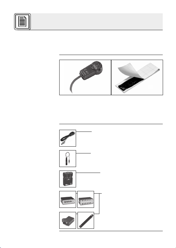
1 C 411
III
Klebemasse
Kontrollieren Sie bitte, ob die Verpackung alle
oben angeführten Teile enthält. Falls etwas fehlt,
wenden Sie sich bitte an Ihren AKG-Händler.
• Mikrofonkabel MK 9/10: 10 m 2-polig
geschirmtes Kabel mit XLR-Stecker
und XLR-Kupplung
• Phantomspeiseadapter
MPA III L (für C 411
• Batteriespeisegerät
B 29 L (für C 411
III
III
• Phantomspeise ge räte
N 62 E, N 66 E,
B 18, B 15
(für C 411
III
PP)
L)
L)
2
Page 3

1 Beschreibung
• Robuster Körperschallwandler für Instrumentalabnahme auf der Bühne.
• Frequenzgang speziell für akustische Gitarre,
Banjo, Zither und Streichinstrumente ausgelegt.
• Klebemasse für die direkte Montage am Instrument im Lieferumfang enthalten.
Der Pickup C 411
III
ist ein Körperschallwandler
und nimmt den Schall direkt von der Oberfläche
des schwingenden Resonanzkörpers eines akustischen Instruments auf.
Der Pickup wurde speziell für die direkte Montage
an akustischen Gitarren, Banjos, Zithern und
Streichinstrumenten entwickelt und garantiert eine
absolut klangtreue, unverfälschte Wiedergabe Ihres Instruments.
Die Klebemasse zur Befestigung des Pickups ist
absolut unschädlich für Holz-, Kunststoff- und
Metalloberflächen.
Der Pickupist in zwei Ausführungen erhältlich:
• Für 9 bis 52 V Universal-Phantomspeisung.
3 m langes, fix verbundenes Anschlusskabel
mit Phantomspeiseadapter mit integriertem
3-poligem XLR-Stecker.
• Für Speisung mittels Batteriespeisegerät
B 29 L, Phantomspeiseadapter MPA III L oder
AKG.WIRELESS-Taschensender. 1,5 m langes, fix verbundenes Anschlusskabel mit
3-poligem Mini-XLR-Stecker.
1.4 Besondere
Merkmale
1.5 Kurz beschreibung
1.6 Varianten
III
C 411
C 411
PP
III
L
3
Page 4

2 Anschluss
2.1 Einleitung
Der C 411
und benötigt daher eine Stromversorgung.
III
Pickup ist ein Kondensatorwandler
Wichtig!
쇵
2.2 C 411
2.2.1 Anschluss
an symmetri-
sche Eingänge
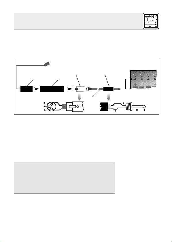
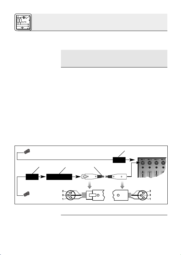
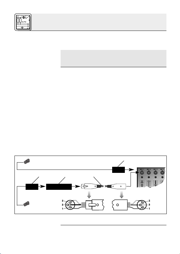
Siehe Abb. 1.
MPA
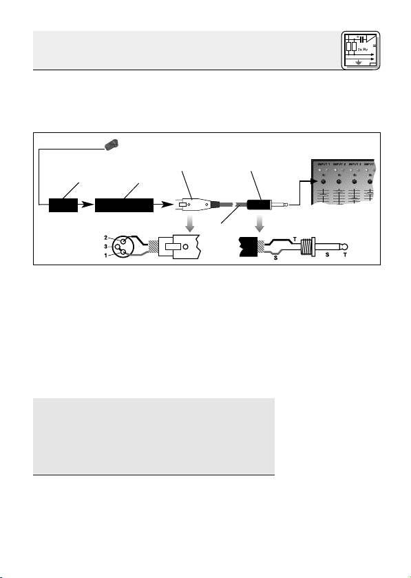
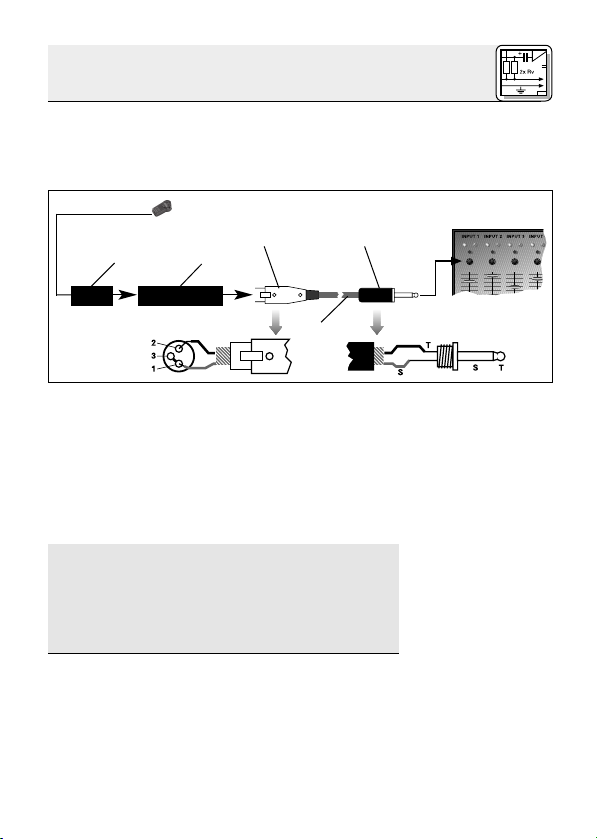
Abb. 1: Anschluss an symmetrischen Eingang
Wenn Sie andere als die von AKG empfohlenen Speisegeräte verwenden, kann der
Pickup beschädigt werden und erlischt
die Garantie.
III
PP
1. Stecken Sie den Phantomspeiseadapter (1) am
Kabel des Pickups an einen symmetrischen
XLR-Mikrofoneingang mit Phantom speisung an.
2. Schalten Sie die Phantomspeisung ein. (Lesen
Sie dazu in der Betriebsanleitung des jeweiligen Gerätes nach.)
3. Wenn Ihr Mischpult keine Phantom -
speisung besitzt, stecken Sie den
Phantomspeiseadapter (1) an ein optionales
AKG-Phantom speise gerät (2) (N 62 E, N 66 E,
B 18, B 15) an und verbinden Sie das
Phantomspeisegerät mit Hilfe eines XLRKabels (3) (z.B. AKG MK 9/10 - nicht mitgliefert) mit einem symmetrischen Eingang.
Phantom
MPA
4
Page 5
2 Anschluss
Phantomspeisegeräte (2) von AKG können Sie auch
an einen asymmetrischen Eingang an schließen.
Verwenden Sie dazu ein Kabel (3) mit XLRStecker (weiblich) und Mono-Klinkenstecker:
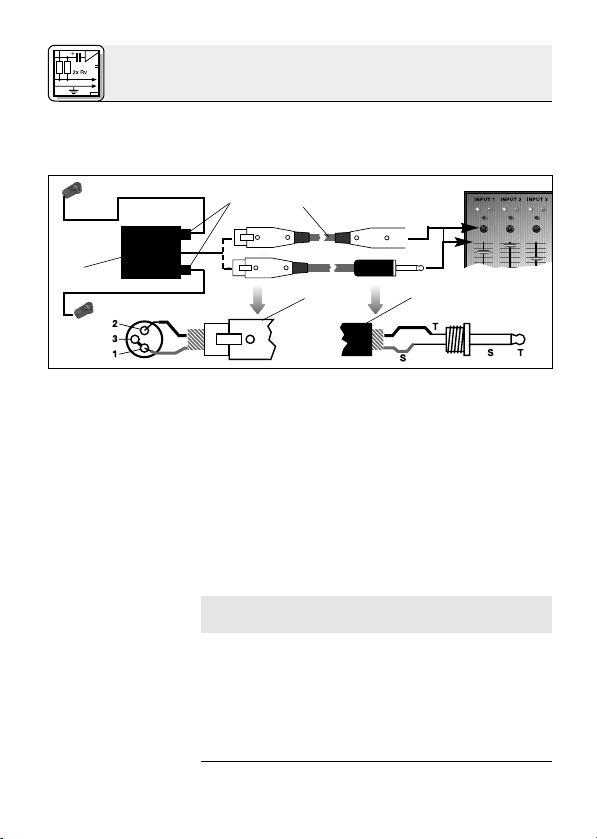
PhantomMPA
Abb. 2: Anschluss an asymmetrischen Eingang
1. Verbinden Sie im XLR-Stecker (4) mittels einer
Drahtbrücke Stift 1 mit Stift 3 und mit der
Abschirmung.
2. Verbinden Sie die innere Ader des Kabels mit
Stift 2 des XLR-Steckers (4) und der Spitze
des Klinkensteckers (5).
Beachten Sie, dass asymmetrische Kabel Einstreuungen aus Magnetfeldern (von Netz- und
Lichtkabeln, Elektromotoren usw.) wie eine Antenne aufnehmen können . Bei Kabeln, die länger als 5 m sind, kann dies zu Brumm- und
ähnlichen Störgeräuschen führen.
2.2.2 Anschluss
an asymmetrische Eingänge
Siehe Abb. 2.
Hinweis:
☞
5
Page 6
2 Anschluss
2.3 C 411
2.3.1 Anschluss
mittels B 29 L
III
L
Mit dem optionalen Batteriespeisegerät B 29 L
können Sie den Pickup an symmetrische oder
asymmetrische Eingänge ohne Phantomspeisung
anschließen.
B 29 L
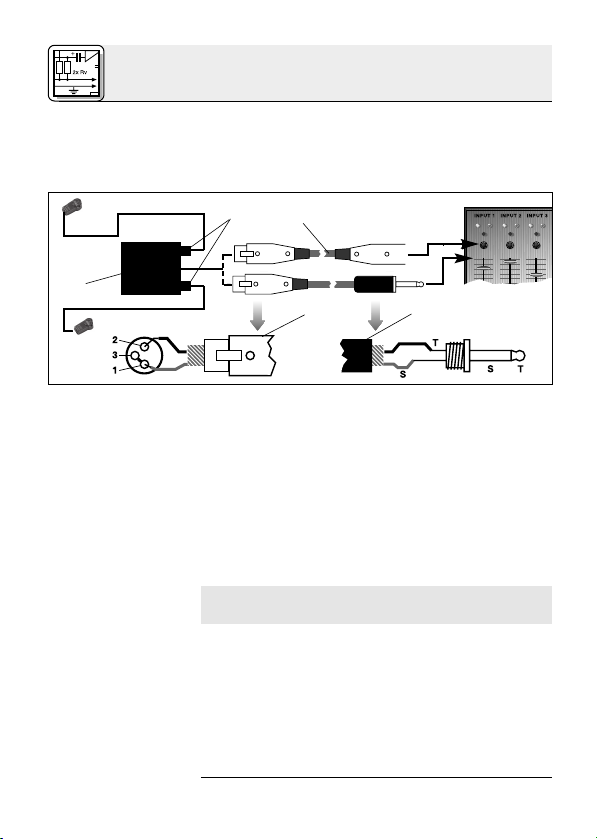
Abb. 3: Anschluss-Schema mit B 29 L
Siehe Abb. 3.
Wichtig!
쇵
Symmetrischer
Eingang:
Siehe Abb. 3.
Asymmetrischer
Eingang:
1. Kabel anstecken: Stecken Sie den Mini-XLR-
Stecker (1) am Kabel des Pickups bis zum
Anschlag in eine der beiden Mini-XLRBuchsen am B 29 L (2).
Der Stecker (1) verriegelt sich automatisch.
Kabel abziehen: Zum Abziehen des Kabels
drücken Sie auf den Entriegelungsknopf am
Mini XLR-Stecker (1) und ziehen Sie den
Stecker (1) aus der Buchse heraus.
Um das Kabel nicht zu beschädigen, ziehen Sie niemals am Kabel selbst!
2. Verbinden Sie das B 29 L (2) mit dem
gewünschten Eingang.
Zum Anschluss an einen symmetrischen
Eingang verwenden Sie ein handelsübliches
XLR-Kabel (3).
Siehe Kapitel 2.2.2.
6
Page 7
2 Anschluss
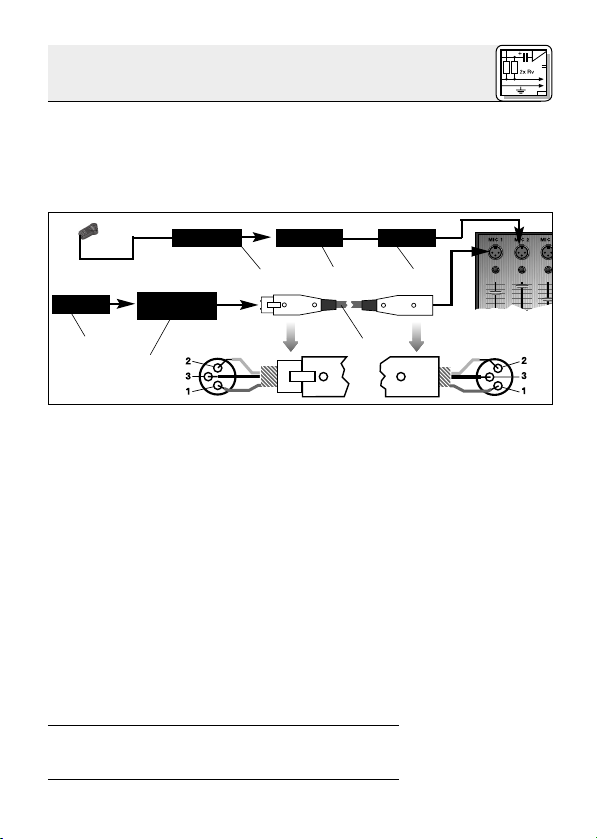
1. Kabel anstecken: Stecken Sie den Mini-XLR-
Stecker (1) am Kabel des Pickups bis zum
Anschlag in die Mini-XLR-Kupplung (2) am
Anschlusskabel des MPA III L (3).
Der Stecker (1) verriegelt sich automatisch.
Mini XLR Mini XLR MPA
MPA
Phantom
Abb. 4: Anschluss-Schema mit MPA III L
Kabel abziehen: Siehe Kapitel 2.3.1.
2. Stecken Sie den MPA III L (3) an einen symmetrischen XLR-Mikrofoneingang mit
Phantomspeisung an.
3. Schalten Sie die Phantomspeisung ein. (Lesen
Sie dazu in der Betriebsanleitung des jeweiligen Gerätes nach.)
4. Wenn Ihr Mischpult keine Phantom -
speisung besitzt, stecken Sie den MPA III L
(3) an ein optionales AKG-Phantom speise gerät (4) (N 62 E, N 66 E, B 18, B 15) an und
verbinden Sie das Phantomspeisegerät (4) mit
Hilfe eines XLR-Kabels (5) (z.B. AKG MK 9/10
- nicht mitgliefert) mit einem symmetrischen
Eingang.
2.3.2 Anschluss
mittels MPA III L
Siehe Abb. 4.
Siehe Abb. 4.
Lesen Sie in der Bedienungsanleitung Ihres
Taschensenders nach.
2.3.3 Anschluss an
Taschensender
7
Page 8

3 Anwendung
3.1 Einleitung
3.2 Befestigung
am Instrument
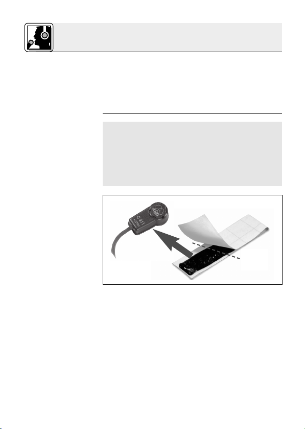
☞
Hinweis:
Abb. 5: Klebe-
masse auf die
Unterseite des
Pickups drücken.
Siehe Abb. 6 bis 9
auf Seite 9.
Da die Resonanzkörper akustischer Instrumente
an verschiedenen Punkten in unterschiedlicher
Weise schwingen, können Sie durch Variieren des
Schallabnahmepunkts verschiedene Klangfarben
erhalten.
Bewährte Positionierungen und weitere Anwendungshinweise finden Sie in Kapitel 3.2.
Wenn Sie den Pickup auf einer lackierten Oberfläche befestigen wollen, kontrollieren Sie vorher
den Zustand des Lacks.
Auf porösem, brüchigem Lack ist die Haltekraft
der Klebemasse geringer und es besteht die Gefahr, dass die Klebemasse beim Entfernen des
Pickups die Lackschicht weiter beschädigt.
✂
1. Ziehen Sie die Schutzfolie von der mitgelieferten Klebemasse ab.
2. Drücken Sie einen Teil der Klebemasse (etwa
gleich groß wie der Pickup) auf die Unterseite
des Pickups.
3. Drücken Sie den Pickup auf den Steg oder in
der Nähe des Stegs auf die Decke des Instruments.
8
Page 9

3 Anwendung
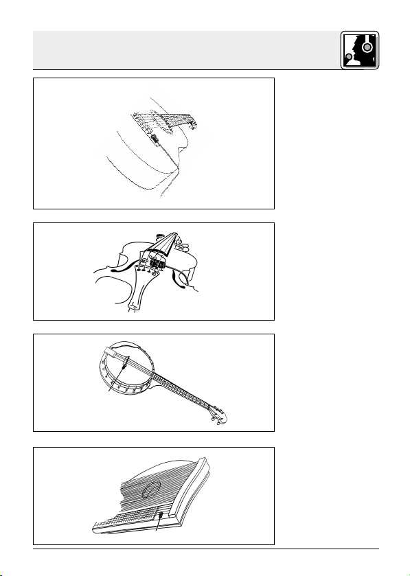
Abb. 6: Gitarre
Abb. 7: Violine
Abb. 8: Banjo
Abb. 9: Zither
9
Page 10

5 Fehlerbehebung
Fehler
Kein Ton:
Verzerrungen:
Mögliche Ursache
1. Mischpult und/oder
Verstärker ausgeschaltet.
2. Kanal-Fader oder
Summenpegelregler
am Mischpult oder
Lautstärkeregler des
Verstärkers steht auf
Null.
3. Pickup nicht an
Mischpult oder
Verstärker angeschlossen.
4. Kabelstecker nicht
richtig angesteckt.
5. Kabel defekt.
6. Keine Speise spannung.
1. Gain-Regler am
Mischpult zu weit
aufgedreht.
2. Mischpulteingang zu
empfindlich.
Abhilfe
1. Mischpult und/oder
Verstärker ein schalten.
2. Kanal-Fader oder
Summenpegelregler
am Mischpult oder
Lautstärkeregler des
Verstärkers auf gewünschten Pegel
ein stellen.
3. Pickup an Mischpult
oder Verstärker an schließen.
4. Kabelstecker
nochmals anstecken.
5. Kabel überprüfen
und falls nötig er setzen.
6. Phantomspeisung
einschalten.
Phantomspeisegerät: ans Netz
anschließen bzw.
Batterie(n) einlegen.
Kabel überprüfen
und falls nötig er setzen.
1. Gain-Regler zurückdrehen.
2. 10-dB-Vorabschwächung
zwischen Pickupkabel und Eingang
stecken.
10
Page 11
6 Technische Daten
Arbeitsweise: Kondensatorwandler mit Permanentladung
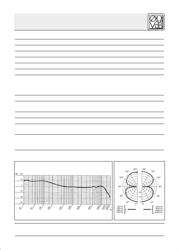
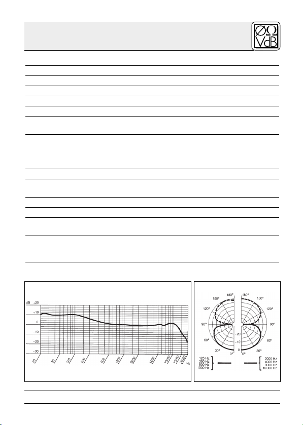
Richtcharakteristik: Achter
Übertragungsbereich: 10 – 18.000 Hz
Empfindlichkeit: 1 mV/ms-2(Körperschallwandler)
Elektrische Impedanz bei 1000 Hz: 200 Ω asymmetrisch
Empfohlene Lastimpedanz: ≥1000 Ω
Grenzschalldruck für 1 % / 3% Klirrfaktor: 96 dB / 103 dB
Speisespannung: C 411
Stromaufnahme: ca. 2,2 mA
Kabellänge/Steckerart: C 411
Oberfläche: mattschwarz
Abmessungen: 27 x 14 x 9,5 mm
Netto/Bruttogewicht: C 411
Dieses Produkt entspricht den in der Konformitätserklärung angegebenen
Normen. Sie können die Konformitätserklärung auf http://www.akg.com oder
per E-Mail an sales@akg.com anfordern.
Frequenzgang Polardiagramm
III
PP: 9–52 V Phantomspeisung
III
L: Batteriespeisegerät B 29 L,
C 411
Phantomspeiseadapter MPA III L, AKG
WMS Taschensender
III
PP: 3 m / XLR 3-polig
III
C 411
L: 1,5 m / Mini-XLR 3-polig
III
PP: 98 g / 225 g
III
C 411
L: 18 g / 150 g
Reinigung: Reinigen Sie das Gehäuse des Pickups mit einem mit Wasser befeuchteten Tuch.
11
Page 12
1 Precaution/Description
1.1 Precaution
1.2 Unpacking
1.3 Optional
Accessories
Please make sure that the piece of equipment
your pickup will be connected to fulfills the safety
regulations in force in your country and is fitted
with a ground lead.
1 C 411
III
Adhesive compound
Check that the packaging contains all of the components listed above. Should anything be miss ing, please contact your AKG dealer.
• MK 9/10 microphone cable: 10-m
(30-ft.) 2-conductor shielded cable
w/male and female XLR connectors
• MPA III L phantom power adapter
(for C 411
• B 29 L battery power supply
(for C 411
III
III
• N 62 E, N 66 E, B 18, B15
phantom power suppplies
(for C 411
III
PP)
L)
L)
12
Page 13

1 Description
• Rugged vibration pickup for instrument miking
on stage.
• Frequency response tailored to acoustic guitar,
banjo, zither, and bowed string instrument miking.
• Complete with adhesive compound for mount ing the pickup directly on the instrument.
The C 411
III
is a vibration pickup that converts the
vibrations of an instrument’s soundboard into an
electrical signal.
The C 411
III
has been specifically designed for
direct attachment to an acoustic guitar, banjo,
zither, or bowed string instrument and ensures
absolutely accurate, coloration-free reproduction.
The supplied adhesive compound for attaching
the pickup will leave wooden, plastic, and metal
surfaces untainted.
The C 411
III
is available in two versions:
• For 9 to 52 V universal phantom power. 10-ft.
(3-m) permanently attached connecting cable
with phantom power adapter with integrated
3-pin XLR connector.
• For use with the B 29 L battery power supply,
MPA III L phantom power adapter, or
AKG.WIRE LESS bodypack transmitters. 5-ft.
(1.5-m) permanently attached connecting cable with 3-pin mini XLR connector
1.4 Features
1.5 Brief
Description
1.6 Versions
III
C 411
C 411
PP
III
L
13
Page 14
2 Interfacing
2.1 Introduction
The C 411
therefore needs a power supply.
III
pickup is a condenser transducer and
Important!
쇵
2.2 C 411
2.2.1 Connecting
to Balanced
Inputs
Refer to fig. 1.
MPA
Fig. 1: Connecting to a balanced input.
Using any power supply other than those
recommended by AKG may damage your
pickup and will void the warranty.
III
PP
1. Connect the phantom power adapter (1) on the
pickup cable to a balanced XLR microphone
input with phantom power.
2. Switch the phantom power on. (Refer to the instruction manual of the unit to which you
connected your pickup.)
3. If your mixer provides no phantom power:
Connect the phantom power adapter (1) to an
optional AKG phantom power supply (2) (N 62 E,
N 66 E, B 18, B 15) and use an XLR cable (3)
(e.g., an optional MK 9/10 from AKG) to connect
the phantom power supply to the desired balanc ed input.
Phantom
MPA
14
Page 15

2 Interfacing
You may connect any AKG phantom power supply (2) to an unbalanced input, too.
Use a cable (3) with a female XLR connector and
TS jack plug:
PhantomMPA
Fig. 2: Connecting to an unbalanced input.
1. On the XLR connector (4), use a wire bridge to
connect pin 1 to pin 3 and the cable shield.
2. Connect the inside wire of the cable to pin 2
on the XLR connector (4) and the tip contact
of the jack plug (5).
3. Connect the shield of the cable to the shaft
contact on the jack plug (5).
Unbalanced cables may pick up interference
from stray magnetic fields near power or lighting
cables, electric motors, etc. like an antenna.
This may introduce hum or similar noise if you
use a cable that is longer than 16 feet (5 m).
2.2.2 Connecting
to Unbalanced
Inputs
Refer to fig. 2.
Note:
☞
15
Page 16
2 Interfacing
2.3 C 411
2.3.1 Using the
Optional B 29 L
III
L
The optional B 29 L battery supply allows you to
connect the pickup to balanced or un balanced
inputs with no phantom power.
B 29 L
Fig. 3: Using the B 29 L to power the microphone.
Refer to fig. 3.
Important!
쇵
Refer to fig. 3.
Balanced input:
Unbalanced input:
1. Connecting the cable: Push the mini XLR
connector (1) on the pickup cable into one of
the two mini XLR sockets on the B 29 L (2) to
the stop.
The connector will lock automatically.
Disconnecting the cable: To disconnect the
cable, press the unlocking button on the mini
XLR connector (1) and pull the connector (1)
out of the socket.
To avoid damaging the cable, never try to
pull out the cable itself!
2. Connect the B 29 L (2) to the desired input.
• Use a commercial XLR cable (3) to connect
• Refer to section 2.2.2 above.
the B 29 L (2) to a balanced input.
16
Page 17

2 Interfacing
1. Connecting the cable: Push the mini XLR
connector (1) on the pickup cable into the mini
XLR socket (2) on the cable of the MPA III L (3)
to the stop.
The connector will lock automatically.
Mini XLR Mini XLR MPA
MPA
Phantom
Fig. 4: Connection diagram with MPA III L.
Disconnecting the cable: Refer to section
2.3.1 above.
2. Connect the MPA III L (3) to a balanced XLR
microphone input with phantom power.
3. Switch the phantom power on. (Refer to the instruction manual of the unit to which you
connected your pickup.)
4. If your mixer provides no phantom power:
Connect the MPA III L (3) to an optional AKG
phantom power supply (4) (N 62 E, N 66 E, B 18,
B 15) and use an XLR cable (5) (e.g., an optional
MK 9/10 from AKG) to connect the phantom
power supply (4) to the desired balanc ed input.
2.3.2 Using the
MPA III L
Refer to fig. 4.
Refer to fig. 4.
Refer to the manual of your bodypack transmitter.
2.3.3 Connecting
to a Bodypack
Transmitter
17
Page 18
3 Use
3.1 Introduction
3.2 Attaching
the Pickup to
the Instrument
☞
Note:
Fig. 5: Pressing the
adhesive com -
pound on the
underside of the
pickup.
Refer to figs. 6
through 9
on page 19.
Since a soundboard vibrates differently in different
places, you can get diferent sounds by carefully
selecting the spot where you mount the pickup.
Section 3.2 describes proven techniques that you
may want to use as starting points for your own
experiments.
If you are going to attach the pickup to a lacquer ed surface, check the condition of the lacquer
coat first.
If the lacquer coat is porous or cracked, the ad hesive compound will lose some of its tack and
may damage the lacquer coat further when you remove the pickup.
✂
1. Remove the backing from the supplied ad hesive compound.
2. Press some of the adhesive compound (just
enough to cover the "footprint" of the pickup)
on the underside of the pickup.
3. Press the pickup onto the bridge of your instrument or onto the soundboard, near the bridge.
18
Page 19
3 Use
Fig. 6: Guitar
Fig. 7: Violin
Fig. 8: Banjo
Fig. 9: Zither
19
Page 20
5 Troubleshooting
Problem
No sound:
Distortion:
Possible Cause
1. Power to mixer
and/or amplifier is
off.
2. Channel or master
fader on mixer, or
volume control on
amplifier is at zero.
3. Pickup is not
connected to mix er or amplifier.
4. Cable connectors
are seated loosely.
5. Cable is defective.
6. No supply voltage.
1. Gain control on
the mixer set too
high.
2. Mixer input sensitivity too high.
Remedy
1. Switch power to
mixer or amplifier
on.
2. Set channel or
master fader on
mixer or volume
control on amplifier to desired
lev el.
3. Connect pickup to
mixer or amplifier.
4. Check cable
connectors for secure seat.
5.
Check cable and replace if damaged.
6. Switch phantom
power on.
Phantom power
supply: connect to
power outlet or insert battery
(batteries).
Check cable and replace if necessary.
1. Turn gain control
down CCW.
2. Connect a 10-dB
preattenuation
pad between
pickup cable and
input.
20
Page 21

6 Specifications
Type: pre-polarized condenser transducer
Polar pattern: figure 8
Frequency range: 10 Hz to 18,000 Hz
Sensitivity at 1 kHz: 1 mV/ms
Impedance: 200 Ω, unbalanced
Recommended load impedance: ≥1000 Ω
Max. SPL for 1%/3% THD: 96 / 103 dB SPL
Power requirement:
Current consumption: approx. 2.2 mA
Cable length/Connector: C 411
Finish: matte black
Size: 27 x 14 x 9.5 mm (1 x 0.6 x 0.4 in.)
Net/shipping weight: C 411
This product conforms to the standards listed in the Declaration of Conformity.
To order a free copy of the Declaration of Conformity, visit http://www.akg.com
or contact sales@akg.com.
Frequency Response Polar Diagram
-2
(vibration pickup)
III
C 411
PP: 9 to 52 V universal phantom power
III
L: B 29 L battery power supply,
C 411
MPA III L phantom adapter,
AKG WMS bodypack transmitters
III
PP: 3 m (10 ft.) / 3-pin male XLR
III
C 411
L: 1.5 m (5 ft.) / 3-pin mini XLR
III
PP: 98 g (3.5 oz.) / 225 g (8 oz.)
III
C 411
L: 18 g (0.6 oz.) / 150 g (5.3 oz.)
Cleaning: To clean the pickup case, use a soft cloth moistened with
water.
21
Page 22

1 Consigne de sécurité / Description
1.1 Consigne de
sécurité
1.2 Fournitures
1.3 Accessoires
optionnels
Vérifiez si l’appareil auquel vous voulez raccorder
le micro-contact répond aux prescriptions relatives à la sécurité en vigueur et s’il possède une
mise à la terre de sécurité.
1 C 411
III
Mastic
Contrôlez si le carton contient bien tous les éléments énumérés ci-dessus. Si ce n’est pas le cas,
veuillez contacter votre distributeur AKG.
•
Câble de micro MK 9/10 : câble blindé
bipolaire de 10 m, avec connecteurs
XLR mâle et femelle
• Adaptateur pour alimentation
fantôme MPA III L (pour C 411
• Alimentations à piles
B 29 L (pour C 411
•
Appareils d’alimentation fantôme
N 62 E, N 66 E, B 18, B 15
(pour C 411
III
III
III
PP)
L)
L)
22
Page 23

1 Description
• Micro-contact robuste pour la prise d’instruments sur scène.
• Réponse en fréquence spécialement adaptée
pour la guitare acoustique, le banjo, la cithare
et des instruments à cordes.
• Du mastic pour le montage direct sur l’instrument est fourni avec le micro.
Le micro-contact C 411
III
est un transducteur de
vibrations de structure qui prend le son directement à la surface de la caisse de résonnance en
vibration d’un instrument acoustique.
Le C 411
III
a été conçu spécialement pour le montage direct sur la guitare acoustique, le banjo, la
cithare et des instrumens à cordes et garantit toujours une restitution absolument fidèle et non dénaturée de votre instrument.
Le mastic pour la fixation du micro-contact ne risque absolument pas d’abîmer le bois, la matière
plastique ou la surface métallique.
Le micro-contact existe en deux versions
différentes:
• Pour alimentation fantôme universelle de 9 à
52 V. Câble de raccordement fixe de 3 m de long
avec module d’alimentation fantôme comportant un connecteur XLR 3 points intégré.
• Pour alimentation par boîtier à pile B 29 L, mo-
dule d’alimentation fantôme MPA III L ou émetteur de poche AKG.WIRELESS. Câble de raccordement fixe de 1,5 m de long, avec connecteur mini-XLR 3 points.
1.4
Caractéristiques
particulières
1.5 Description
succincte
1.6 Versions
III
C 411
PP
III
C 411
L
23
Page 24

2 Raccordement
2.1 Introduction
Le micro-contact C 411
trostatique ; il a donc besoin d’une alimentation.
III
est un transducteur élec-
Important!
쇵
2.2 C 411
Raccordement
sur une entrée
symétrique
Voir fig. 1.
MPA
Fig. 1 : Raccordement sur une entrée symétrique
L’utilisation d’alimentations autres que celles recommandées par AKG peut provoquer
des dégâts sur le micro et entraîne la perte
de la garantie.
III
PP
1. Connectez l’adaptateur pour alimentation
2.2.1
Phantom
fantôme (1) du câble micro sur une entrée de
micro symétrique type XLR avec alimentation
fantôme.
2. Mettez l’alimentation fantôme sous tension
(Veuillez vous reporter à la notice de l’alimentation utilisée).
3. Si vous n’avez pas d’alimentation
fantôme sur votre table de mixage, branchez l’adaptateur pour alimentation fantôme
(1) sur une alimentation fantôme AKG optionnelle (2) (N 62 E, N 66 E, B 18, B 15) et raccordez l’alimentation fantôme à une entrée
symétrique à l’aide d’un câble XLR (3) (p.ex.
AKG MK 9/10 – n’est pas fourni avec le micro).
MPA
24
Page 25

2 Raccordement
Vous pouvez aussi connecter les alimentations fantôme
d’AKG (2) sur une entrée asymétrique.
Il vous faut un câble (3) avec une fiche XLR femelle
et une fiche à jack mono:
PhantomMPA
Fig. 2 : Raccordement sur une entrée asymétrique
1. Pontez les contacts 1 et 3 de la fiche XLR (4) et
reliez-les au blindage du câble.
2. Reliez le conducteur interne du câble au
contact 2 de la fiche XLR (4) et à la pointe de la
fiche à jack (5).
3.
Reliez le blindage du câble à la tige de la fiche à jack.
Les câbles asymétriques peuvent capter
comme une antenne les interférences de
champs magnétiques (câbles lumière ou force,
moteurs électriques, etc.). Si le câble mesure
plus de 5 m ce phénomène pourra se traduire
par des ronflements et autres parasites.
2.2.2
Raccordement
sur une entrée
asymétrique
Voir Fig. 2.
N.B.
☞
25
Page 26

2 Raccordement
2.3 C 411
Raccordement
au moyen du
III
2.3.1
B 29 L
Voir Fig. 3.
L
L’alimentation à pile B 29 L optionnelle vous permet de raccorder le micro à des entrées symétriques ou asymétriques sans alimentation fantôme.
1. Brancher le câble : Enfoncez le connecteur
mini-XLR (1) du câble du micro à fond dans une
des deux embases mini-XLR du B 29 L (2).
Le connecteur (1) se verrouille automatiquement.
B 29 L
Fig. 3 : Schéma de raccordement avec B 29 L
Débrancher le câble : Pour détacher le câble,
appuyez sur le bouton de déverrouillage du
connecteur mini-XLR (1) et sortez le connecteur de la prise.
Important !
쇵
Entrée symétrique:
Entrée asymétrique:
26
Cf. Fig. 3.
Pour ne pas risquer d’abîmer le câble, ne
sortez jamais le connecteur en tirant sur
le câble.
2. Raccordez le B 29 L (2) sur l’entrée voulue.
• Pour le raccordement sur une entrée sym-
• Voir point 2.2.2.
étrique, utilisez un câble XLR (3) en vente
dans le commerce.
Page 27

2 Raccordement
1.
Brancher le câble :
Enfoncez le connecteur
mini-XLR (1) du câble micro jusqu’en butée
dans l’accouplement mini-XLR (2) du câble de
raccordement du MPA III L (3).
Le connecteur (1) se verrouille automatiquement.
Mini XLR Mini XLR MPA
MPA
Phantom
Fig. 4: Schéma de raccordement avec MPA III L
Débrancher le câble : Voir point 2.3.1.
2. Connectez le MPA III L (3) sur une entrée de
micro symétrique type XLR avec alimentation
fantôme.
3. Mettez l’alimentation fantôme sous tension
(Veuillez vous reporter à la notice de l’alimentation utilisée).
4. Si vous n’avez pas d’alimentation
fantôme sur votre table de mixage, branchez le MPA III L (3) sur une alimentation
fantôme AKG optionnelle (4) (N 62 E, N 66 E,
B 18, B 15) et raccordez l’alimentation fantôme
à une entrée symétrique à l’aide d’un câble
XLR (5) (p.ex. AKG MK 9/10 – n’est pas fourni
avec le micro).
Conformez-vous aux instructions du mode d’emploi de votre émetteur de poche.
2.3.2
Raccordement
avec MPA III L
Voir Fig. 4.
Voir Fig. 4.
2.3.3
Raccordement
sur un émetteur
de poche
27
Page 28

3 Utilisation
3.1 Introduction
3.2 Fixation sur
un instrument
☞
N.B. :
Fig. 5: Application
du mastic sur la
face inférieure du
micro-contact.
Voir page 29,
Fig. 6 à 9.
Etant donné que le comportement de vibration
des caisses de résonnance des instruments acoustiques varie suivant les points, vous pouvez obtenir des tonalités différentes en changeant le
point de prise de son.
Pour les positions donnant normalement les meilleurs résultats, veuillez vous reporter au point 3.2
où vous trouverez également des conseils relatifs
à l’utilisation.
Si vous souhaitez fixer le micro-contact sur une
surface vernie, assurez-vous d’abord que le vernis est en bon état.
Le mastic adhère moins bien sur un vernis poreux
ou qui s’écaille et dans ce cas vous risquez en outre d’abîmer un peu plus le vernis en enlevant le
mastic.
✂
1. Enlevez la feuille de protection recouvrant le
mastic fourni avec le micro-contact.
2. Appliquez une partie du mastic (correspondant
en gros à la surface du micro-contact) sur la
base du micro-contact.
3. Appliquez le micro-contact sur le chevalet ou
sur la table de l’instrument, à proximité du chevalet.
28
Page 29

3 Utilisation
Fig. 6: Guitare
Fig. 7: Violon
Fig. 8: Banjo
Fig. 9: Cithare
29
Page 30

5 Dépannage
Problème
Pas de son :
Distorisons :
Cause possible
1. La console de mixage
et/ou l’amplificateur ne
sont pas sous tension.
2. Le fader du canal ou le
réglage de niveau master de la console de
mixage ou le réglage
de niveau sonore de
l’ampli est sur zéro.
3. Le micro n’est pas
connecté à la console
de mixage ou à l’ampli.
4. La fiche est mal enfoncée.
5. Le câble est abîmé.
6. Pas de tension d’alimentation.
1. Le réglage de gain de
la table de mixage est
trop haut.
2. L’entrée de la table de
mixage est trop sensible.
Remède
1. Mettre la console de
mixage et/ou l’amplificateur sous tension.
2. Régler le fader du canal ou le réglage de niveau master de la console de mixage ou le
réglage de niveau sonore de l’ampli sur la
valeur voulue.
3. Connecter le micro à la
console de mixage ou
à l’ampli.
4. Enfoncer la fiche correctement.
5. Contrôler le câble et le
remplacer le cas
échéant.
6. Mettre l’alimentation
fantôme sous tension.
Appareil d’alimentation
fantôme : brancher sur
le secteur ou mettre
une (des) pile(s).
Contrôler le câble et le
remplacer le cas
échéant.
1. Baisser le réglage de
gain.
2. Insérer un pré-atténuateur de sensibilité entre
le câble du micro et
l’entrée.
30
Page 31

6 Caractéristiques techniques
Fonctionnement: transducteur électrostatique à charge per-
manente
Directivité: figure en 8
Réponse en fréquence: 10 … 18.000 Hz
Sensibilité : 1 mV/ms
-2
(transducteur de vibrations)
Impédance électrique à 1.000 Hz: 200 Ω, asymmétrique
Impédance de charge recommandée: ≥1000 Ω
Niveau maximum de pression sonore pour 1% / 3% de DHT: 96 / 103 dB SPL
III
Tension d’alimentation: C 411
PP: 9 … 52 V, al. fantôme universelle
III
L: alimentation à piles B 29 L,
C 411
adaptateur fantôme MPA III L,
émetteurs de poche AKG WMS
Consommation: env. 2,2 mA
III
Connecteur: C 411
PP: 3 m / type XLR, 3 points
III
C 411
L: 1,5 m / type mini-XLR, 3 points
Couleur: noir mat
Dimensions: 27 x 14 x 9,5 mm
III
Poids net/brut : C 411
C 411
III
PP: 98 g / 225 g
L: 18 g / 150 g
Ce produit est conforme aux normes citées dans la Déclaration de
Conformité, dont vous pouvez prendre connaissance en consultant le site
http://www.akg.com ou en adressant un e-mail à sales@akg.com.
Réponse en fréquence Diagramme polaire
Nettoyage : Le boîtier du micro se nettoie avec un chiffon légèrement
humide (eau claire).
31
Page 32

1 Indicazione per la sicurezza / Descrizione
1.1 Indicazione
per la sicurezza
1.2 In dotazione
1.3 Accessori
raccomandati
Controllate per favore se l’apparecchio che volete
collegare al pickup corrisponde alle norme di sicurezza vigenti e se è dotato di una messa a terra di
sicurezza.
1 C 411
III
Massa adesiva
Controllate per favore se la confezione contiene
tutti i componenti di cui sopra. Se manca qualcosa rivolgetevi al vostro rivenditore AKG.
• Cavo microfonico MK 9/10: cavo lungo
10 m, schermato, a 2 poli, con connettore
XLR e accoppiamento XLR.
• Adattatore phantom
MPA III L (per C 411
• Alimentatore a batteria
B 29 L (per C 411
III
III
• Alimentatori phantom
N 62 E, N 66 E, B 18, B 15
(per C 411
III
PP)
L)
L)
32
Page 33

1 Descrizione
• Robusto convertitore di vibrazioni per la ripresa di strumenti sul palco.
• Risposta in frequenza ideata specialmente per
chitarra acustica, banjo, cetra e strumenti ad
arco.
• Massa adesiva per il montaggio diretto sullo
strumento in dotazione.
Il pickup C 411
III
è un convertitore di vibrazioni e
assorbe il suono direttamente dalla superficie del
corpo risonante vibrante di uno strumento acustico.
III
Il C
411
è stato sviluppato specialmente per il montaggio diretto su chitarre acustiche, banjo, cetre e
strumenti ad arco, e garantisce una riproduzione assolutamente fedele e genuina del vostro strumento.
La massa adesiva per il fissaggio del pickup è assolutamente innocua per ogni superficie di legno, plastica o metallo.
Il pickup è disponibile in due versioni:
• Per alimentazione phantom universale da 9 a
52 V. Cavo di collegamento lungo 3 m, fisso,
con adattatore phantom e connettore XLR a tre
poli integrato.
• Per alimentazione mediante alimentatore a
batterie B 29 L, adattatore per alimentazione
phantom MPA III L oppure trasmettitore da tasca AKG.WIRELESS. Cavo di collegamento
lungo 1,5 m, fisso, con connettore mini XLR a
tre poli.
1.4
Caratteristiche
particolari
1.5 Breve
descrizione
1.6 Varianti
III
C 411
C 411
PP
III
L
33
Page 34

2 Collegamento
2.1 Introduzione
III
Il C 411
quindi bisogno di alimentazione.
è un trasduttore a condensatore e ha
Importante!
쇵
2.2 C 411
Collegamento
ad ingressi
simmetrici
Vedi fig. 1.
MPA
Fig. 1: Collegamento ad un ingresso simmetrico
Se usate alimentatori diversi da quelli raccomandati dall’AKG, il pickup può subire
danni e la garanzia si estingue.
III
PP
1. Collegate l’adattatore per l’alimentazione
2.2.1
Phantom
phantom (1) disposto sul cavo del pickup a un
ingresso microfonico XLR simmetrico con alimentazione phantom.
2. Inserite l’alimentazione phantom. (Leggete in merito
le istruzioni per l’uso del rispettivo apparecchio.)
3. Se il vostro mixer non è dotato di alimen-
tazione phantom, inserite l’adattatore per alimentazione phantom (1) in un alimentatore
phantom AKG opzionale (2) (N 62 E, N 66 E,
B 18, B 15) e collegate l’alimentatore phantom
servendovi di un cavo XLR (3) (p.e. AKG
MK 9/10 – non in dotazione) ad un ingresso
simmetrico.
MPA
34
Page 35

2 Collegamento
Gli alimentatori phantom (2) dell’AKG possono venir collegato anche ad un ingresso asimmetrico.
Usate un cavo (3) con una presa XLR (4) e una
spina jack mono (5):
PhantomMPA
Fig. 2: Collegamento ad un ingresso asimmetrico
1. Nella presa XLR (4), collegate con un ponte a filo i
contatti 1 e 3 e portateli sullo schermo del cavo.
2. Collegate il conduttore interno del cavo con il
contatto 2 della presa XLR (4) e la punta della
spina jack (5).
3. Collegate lo schermo del cable con il gambo
della spina jack.
Tenete presente che i cavi asimmetrici possono assorbire, come un’antenna, irradiazioni
da campi magnetici (cavi di rete, cavi della
luce, elettromotori ecc.). Nel caso di cavi la cui
lunghezza supera i 5 m, questo fenomeno può
causare ronzìi ed altri rumori disturbanti.
2.2.2
Collegamento
ad ingressi
asimmetrici
Vedi fig. 2.
Nota:
☞
35
Page 36

2 Collegamento
2.3 C 411
Collegamento
con B 29 L
III
2.3.1
L
Con l’alimentatore a batterie opzionale B 29 L potete collegare il pickup ad ingressi simmetrici o
asimmetrici senza alimentazione phantom.
B 29 L
Fig. 3: Schema di collegamento con B 29 L
Vedi fig. 3.
Importante!
쇵
Vedi fig. 3.
Ingresso
simmetrico:
Ingresso
asimmetrico:
1. Inserire il cavo: Inserite il connettore mini-XLR
(1) sul cavo del pickup in una delle due prese
mini-XLR sul B 29 L (2) fino all’arresto.
Il connettore (1) si blocca automaticamente.
Sfilare il cavo: Per sfilare il cavo, premete il
bottone di sblocco sul connettore mini-XLR (1)
e sfilate il connettore (1) dalla presa.
Per non danneggiare il cavo, non esercitate mai trazione direttamente sul cavo!
2. Collegate il B 29 L (2) con l’ingresso prescelto.
• Per il collegamento ad un ingressso simme-
• Vedi capitolo 2.2.2.
trico servitevi di un cavo XLR commerciale (3).
36
Page 37

2 Collegamento
1. Inserire il cavo: Inserite il connettore mini-XLR
(1) disposto sul cavo del pickup fino all‘arresto
nell‘accoppiamento mini-XLR (2) disposto sul
cavo di collegamento dell’MPA III L (3).
Il connettore (1) si blocca automaticamente.
Mini XLR Mini XLR MPA
MPA
Phantom
Fig. 4: Schema di collegamento con MPA III L
Sfilare il cavo: Vedi capitolo 2.3.1.
2. Collegate l’MPA III L (3) disposto sul cavo del
pickup a un ingresso microfonico XLR simmetrico con alimentazione phantom.
3. Inserite l’alimentazione phantom. (Leggete in
merito le istruzioni per l’uso del rispettivo apparecchio.)
4. Se il vostro mixer non è dotato di alimen-
tazione phantom, inserite l’MPA III L (3) in un
alimentatore phantom AKG opzionale (4) (N 62 E,
N 66 E, B 18, B 15) e collegate l’alimentatore
phantom (4) servendovi di un cavo XLR (5) (p.e.
AKG MK 9/10 – non in dotazione) ad un ingresso simmetrico.
Leggete al riguardo le istruzioni per l’uso del vostro trasmettitore da tasca.
2.3.2
Collegamento
con MPA III L
Vedi fig. 4.
Vedi fig. 4.
2.3.3
Collegamento
ad un trasmettitore da tasca
37
Page 38

3 Impiego
3.1 Introduzione
3.2 Fissaggio
sullo strumento
☞
Nota:
Fig. 5: Premere la
massa adesiva
sulla parte inferiore
del pickup.
Vedi pagina 39,
figg. 6 - 9.
Dato che il corpo risonante vibrante degli strumenti acustici presenta, a seconda dei punti, un
comportamento vibratorio differente, variando il
punto di assorbimento del suono potete ottenere
diversi timbri.
Posizioni del pickup che hanno dato buona prova
ed altre indicazioni d’impiego sono contenute nel
capitolo 3.2.
Se volete fissare il pickup su una superficie verniciata, controllate prima lo stato della vernice.
Su vernice porosa o screpolata, la massa adesiva
non attacca bene; quando il pickup viene rimosso
c’è il pericolo che la massa adesiva danneggi ulteriormente la vernice.
✂
1. Staccate il foglio protettivo dalla massa adesiva in dotazione.
2. Premete una parte della massa adesiva (dimensionata all’incirca come il pickup) sulla
parte inferiore del pickup.
3. Premete il pickup sul ponticello o sulla tavola
armonica dello strumento, vicino al ponticello.
38
Page 39

3 Impiego
Fig. 6: Chitarra
Fig. 7: Violino
Fig. 8: Banjo
Fig. 9: Cetra
39
Page 40

5 Eliminazione di difetti
Difetto
Nessun suono:
Distorsioni:
Possibili cause
1. Mixer e/o amplificatore sono dis inseriti.
2. Fader del canale o regolatore principale
del mixer o regolatore
del volume dell’amplificatore sono in posizione zero.
3. Il pickup non è
collegato al mixer o
all’amplificatore.
4. Il connettore del cavo
non è inserito bene.
5. Il cavo è difettoso.
6. Non c’è alimentazione.
1. Il regolatore gain sul
mixer è aperto
troppo.
2. L’ingresso del mixer è
troppo sensibile.
Rimedio
1. Inserire il mixer e/o
l’amplificatore.
2. Portare al livello desiderato il fader del canale o il regolatore
principale del mixer o
il regolatore del volume dell’amplificatore.
3. Collegare il pickup al
mixer o all’amplificatore.
4. Inserire di nuovo il
connettore del cavo.
5. Controllare il cavo e
sostituirlo se necessario.
6. Inserire l’alimentazione phantom.
Alimentatore phantom: collegarlo alla
rete oppure inserire
batteria(e).
Controllare il cavo e,
se necessario, sostituirlo.
1. Portare indietro il regolatore gain.
2. Inserire un preattenuatore di 10 dB tra il
cavo del pickup e l’ingresso.
40
Page 41
6 Dati tecnici
Modo di funzionamento:
trasduttore a condensatore con carica permanente
Direttività: ipercardioide
Risposta in frequenza: 10 - 18.000 Hz
Sensibilità: 1 mV/ms
-2
(convertitore di vibrazioni)
Impedenza elettrica a 1000 Hz: 200 Ω, asimmetrica
Impedenza di carico raccomandata: ≥1000 Ω
Livello di pressione acustica limite per un coefficiente di distorsione armonica
di 1% / 3%: 96 / 103 dB SPL
Tensione di alimentazione: C 411
III
PP: al. phantom universale 9 - 52 V
III
L: alimentatore a batterie B 29 L,
C 411
adattatore phantom MPA III L,
trasmettitori da tasca AKG WMS
Assorbimento: 2,2 mA circa
III
Lunghezza del cavo / connettore: C 411
PP: 3 m / XLR a 3 poli
III
C 411
L: 1,5 m / mini-XLR a 3 poli
Superficie: nero opaco
Dimensioni: 27 x 14 x 9,5 mm
III
Peso netto/lordo: C 411
C 411
PP: 98 g / 225 g
III
L: 18 g / 150 g
Questo prodotto corrisponde alle norme elencate nella dichiarazione di
conformità, che è disponibile al sito http://www.akg.com oppure all’indirizzo
email sales@akg.com.
Risposta in frequenza Diagramma polare
Pulizia: Pulite la scatola del pickup con un panno inumidito con acqua.
41
Page 42

1 Indicaciones de seguridad / Descripción
1.1 Indicaciones
de seguridad
1.2 Volumen de
suministro
1.3 Accesorios
opcionales
Sírvase verificar si el aparato al cual quiere conectar el pickup cumple con las disposiciones de seguridad vigentes y está equipado con una toma
de tierra de seguridad.
1 C 411
III
Masa adhesiva
Sírvase controlar si el embalaje contiene todas las
piezas indicadas arriba. Si falta algo, le rogamos dirigirse a su distribuidor AKG.
• Cable de micrófono MK 9/10: 10 m
de cable bipolar apantallado con conec-
tor y acoplamiento XLR.
• Adaptador de alimentación
fantasma MPA III L
(para C 411
• Alimentador por batería
B 29 L (para C 411
III
L)
III
L)
• Alimentadores fantasma
N 62 E, N 66 E, B 18
(para C 411
III
PP)
42
Page 43

1 Descripción
• Robusto transductor de vibraciones para la toma
de instrumentos en el escenario.
• Respuesta de frecuencia dimensionada especialmente para guitarra, banjo, cítara, instrumentos de arco.
• Masa adhesiva para el montaje directo en el instrumento incluída en el volumen de suministro.
El pickup C 411
III
es un transductor de vibraciones
que recoge el sonido directamente de la superficie
del cuerpo de resonancia vibrante de un instrumento
acústico.
III
El C 411
ha sido desarrollado especialmente para el
montaje directo en guitarras acústicas, banjos, cítaras e instrumentos de arco. Garantiza una reproducción totalmente fiel y sin falsificar del sonido de su instrumento.
La masa adhesiva para la fijación del pickup es totalmente inofensiva a las superficies de madera, plástico o metálicas.
El pickup puede adquirirse en dos modelos:
• Para alimentación fantasma universal de 9 a 52 V.
Dispone de un cable de conexión fijo de 3 m con
adaptador de alimentación fantasma con conector XLR de 3 polos integrado.
• Para alimentación por medio del alimentador por
batería B 29 L, un adaptador de alimentación fantasma MPA III L o un emisor de bolsillo
AKG.WIRE LESS. Cable de conexión fijo de 1,5 m
con mini-conector XLR de 3 polos.
1.4
Características
especiales
1.5 Breve
descripción
1.6 Variantes
III
C 411
C 411
PP
III
L
43
Page 44
2 Conexión
2.1 Introducción
III
El C
411
cesita, por lo tanto, alimentación de corriente.
es un transductor de condensador y ne-
¡Importante!
쇵
2.2 C
2.2.1 Conexión a
Fig. 1: Conexión a una entrada balanceada
411
entradas
balanceadas
Ver Fig. 1.
MPA
Si se utilizan alimentadores diferentes a los
recomendados por AKG puede dañarse el
pickup, cesando con ello la garantía.
III
PP
1. Conecte el adaptador de alimentación fantasma (1) del cable del pickup a una entrada de
micrófono XLR balanceada con alimentación
fantasma.
2. Concecte la alimentación fantasma (consulte
para ello el Modo de empleo del aparato correspondiente).
3. Si su pupitre de mezclas no tiene ali-
mentación fantasma, enchufe el adaptador
de alimentación fantasma (1) al alimentador de
tensión fantasma de AKG opcional (2) (N 62 E,
N 66 E, B 18, B 15) y conecte luego el alimentador de tensión fantasma a una entrada balanceada utilizando un cable XLR (3) (por ej.:
AKG MK 9/10 - no incluido en el suministro).
Phantom
MPA
44
Page 45
2 Conexión
Los alimentadores fantasma (2) de AKG pueden
conectarse también a una entrada no balanceada.
Use un cable (3) con una hembra de conector XLR
y un conector jack mono:
PhantomMPA
Fig. 2: Conexión a una entrada no balanceada
1. Una mediante un puente de alambre la espiga 1
del conector XLR (4) con la espiga 3 y con la
pantalla del cable.
2. Una el conductor interno del cable con la
espiga 2 del conector XLR (4) y la punta del
conector jack (5).
3. Una la pantalla del cable con el mango del
conector jack (5).
Los cables no balanceados pueden recoger interferencias de campos magnéticos (de los cables de red, de alumbrado, de motores eléctricos, etc.) igual que una antena. En los cables
de más de 5 m de largo, esto puede producir
ruidos de zumbido u otras perturbaciones.
2.2.2 Conexión a
entradas no
balanceadas
Ver Fig. 2.
Nota:
☞
45
Page 46

2 Conexión
2.3 C 411
2.3.1 Conexión
utilizando el
III
B 29 L
Ver Fig. 3.
L
Utilizando el alimentador por batería B 29 L opcional
puede conectar el pickup a entradas balanceadas o
no balanceadas sin alimentación fantasma.
1. Conexión del cable: Para conectar el pickup
al B 29 L, enchufe el conector mini-XLR macho
del cable del pickup (1) en uno de los dos
conectores mini-XLR hembra del B 29 L (2) introduciéndolo hasta que haga tope.
El conector macho (1) queda automáticamente
bloqueado.
B 29 L
Fig. 3: Esquema de conexión con B 29 L
Desconexión del cable: Para desconectar el
cable, presione el desbloqueador del conector
mini-XLR macho (1) y separe el conector macho del cable del pickup (1) del conector hembra del B 29 L (2).
¡Importante!
쇵
46
Ver Fig. 3.
Entrada
balanceada:
Entrada no
balanceada:
¡No tire nunca del cable para desconectarlo porque lo puede dañar!
2. Conecte el B 29 L (2) a la entrada deseada.
• Para conectar el pickup a una entrada ba-
• Ver capítulo 2.2.2.
lanceada, utilice un cable XLR común (3) en
venta en cualquier tienda del ramo.
Page 47

2 Conexión
1. Conexión del cable: Enchufe el conector
mini-XLR (1) del cable del pickup, hasta que
llegue al tope, en el acoplamiento mini-XLR (2)
en el cable de conexión del MPA III L (3).
El conector (1) se enclava automáticamente.
Desconexión del cable: Ver capítulo 2.3.1.
Mini XLR Mini XLR MPA
MPA
Phantom
Fig. 4: Esquema de conexión con MPA III L
2. Conecte el adaptador de alimentación fantasma del cable del pickup a una entrada de
micrófono XLR balanceada con alimentación
fantasma.
3. Concecte la alimentación fantasma (consulte
para ello el Modo de empleo del aparato correspondiente).
4. Si su pupitre de mezclas no tiene ali-
mentación fantasma, enchufe el MPA III L
(3) al alimentador de tensión fantasma de AKG
opcional (4) (N 62 E, N 66 E, B 18, B 15) y
conecte luego el alimentador de tensión fantasma (4) a una entrada balanceada utilizando
un cable XLR (5) (por ej.: AKG MK 9/10 - no incluido en el suministro).
Consulte las instrucciones de uso de su emisor de
bolsillo.
2.3.2 Conexión
mediante el
MPA III L
Ver Fig. 4.
Ver Fig. 4.
2.3.3 Conexión a
un emisor de
bolsillo
47
Page 48

3 Utilización
3.1 Introducción
3.2 Fijación al
instrumento
☞
Nota:
Fig. 5: Pegue masa
adhesiva a la parte
inferior del pickup.
Ver página 49,
Fig. 6 a 9.
Dado que las cajas de resonancia de los instrumentos acústicos tienen diferentes comportamientos de
vibración en los diferentes puntos, puede producir
diferentes timbres variando el punto de toma de sonido.
Las posiciones más seguras y otras indicaciones de
uso las puede encontrar en el Capítulo 3.2.
Si desea fijar el pickup a una superficie laqueada,
debe controlar primero el estado de la laca.
El poder de fijación de la masa adhesiva es menor
sobre laca porosa o resquebrajada y existe el peligro
de que, al despegar el pickup, la masa adhesiva
dañe aún más la superficie laqueada.
✂
1. Quite el envoltorio de protección de la masa adhesiva suministrada.
2. Pegue un trozo de masa adhesiva (de un tamaño
similar al del pickup) a la parte inferior del pickup.
3. Pegue el pickup al puente o a la tapa armónica
del instrumento, cerca del puente.
48
Page 49

3 Utilización
Fig. 6: Guitarra
Fig. 7: Violín
Fig. 8: Banjo
Fig. 9: Cítara
49
Page 50

5 Eliminación de fallos
Fallo
No hay sonido:
Distorsiones:
Causa posible
1. Están desconectados:
el pupitre de mezcla
y/o el amplificador.
2. Están en cero: el fader
del canal o el regulador
del nivel de suma del
pupitre de mezcla o el
regulador de volumen
del amplificador.
3. El pickup no está
conectado al pupitre de
mezcla o al amplificador.
4. Los conectores del cable no están bien enchufados.
5. El cable está dañado
(fallado, defectuoso).
6. No hay tensión de alimentación.
1. El nivel de ganancia de
la mesa de mezcla está
muy alto.
2. La entrada de la mesa
de mezcla es muy sensible.
Eliminación
1. Conectar el pupitre de
mezcla y/o el
amplificador.
2. Ajustar en el nivel deseado el fader, el regulador master del pupitre de mezcla o el regulador de volumen del
amplificador.
3. Conectar el pickup al
pupitre de mezcla o al
amplificador.
4. Enchufar nuevamente
los conectores del cable.
5. Controlar el cable y renovarlo si es necesario.
6. Conecte la alimentación fantasma.
Alimentador de tensión
fantasma: conéctelo a
la red o coloque batería(s).
Controle el cable y, si
es necesario, reemplácelo.
1. Disminuya el nivel de
ganancia con el regulador de ganancia.
2. Conecte un preatenuador de 10 dB entre el
cable del pickup y la
entrada.
50
Page 51

6 Datos técnicos
Modo de funcionamiento: Transductor de condensador con carga
permanente
Característica direccional: Figura de ocho
Gama de frecuencia: 10 - 18000 Hz
Sensibilidad: 1 mV/ms
Impedancia eléctrica a 1000 Hz:
-2
(transductor de vibraciones)
200 Ω, no balanceada
Impedancia de carga recomendada: ≥1000 Ω
Presión sonora límite para 1% / 3% de distorsión no lineal: 96 / 103 dB SPL
III
Tensión de alimentación: C 411
PP: Al. fantasma universal 9 - 52 V
III
L: Alimentador por batería B 29 L,
C 411
adaptador fantasma MPA III L.
emisores de bolsillo AKG WMS
Toma de corriente: Aprox. 2,2 mA
III
Longitud del cable / conector: C 411
PP: 3 m / XLR de 3 polos
III
C 411
L: 1,5 m / mini-XLR de 3 polos
Superficie: Negro opaco
Dimensiones: 27 x 14 x 9,5 mm
III
Peso neto/bruto: C 411
C 411
PP: 98 g / 225 g
III
L: 18 g / 150 g
Este aparato corresponde a las normas citadas en la declaración de
conformidad. Esta última está disponible en el sitio http://www.akg.com o
puede ser solicitada al correo electrónico sales@akg.com.
Respuesta de frecuencia Diagrama polar
Limpieza: Limpie la caja del pickup con un paño humedecido con
agua.
51
Page 52

1 Aviso de segurança / Descrição
1.1 Aviso de
segurança
1.2 Volume de
fornecimento
1.3 Acessórios
opcionais
Certifique-se de que o aparelho ao qual pretende
ligar o pickup está ligado à terra e que corresponde às normas de segurança.
1 C 411
III
Massa adesiva
Verifique se a embalagem contém todos os componentes acima indicados. Caso falte algo, favor
entre em contato com a concessionária da AKG.
• Cabo de microfone MK 9/10: cabo
blindado a dois polos de 10 m com plu-
gue XLR e tomada XLR.
• Adatador de alimentação fantasma
MPA III L (para C 411
• Alimentador a pilhas B 29 L
(para C 411
III
III
• Alimentadores fantasma
N 62 E, N 66 E, B 18, B 15
(para C 411
III
PP)
L)
L)
52
Page 53

1 Descrição
• Captador de vibração robusto para captação
instrumental em palcos.
• A resposta de freqüência é concebida especialmente para a captação da guitarra acústica, do banjo, da cítara e de instrumentos de
arco.
• Massa adesiva para a montagem direta no instrumento incluída na embalagem.
O pickup C 411
III
é um captador de vibração que
converte a vibração do corpo de um instrumento
acústico em sinal elétrico.
O C 411
III
foi desenvolvido especialmente para a
montagem direta em guitarras acústicas, banjos,
cítaras e instrumentos de arco, e garante uma reprodução absolutamente fiel e livre de coloração do
som de seu instrumento.
A massa adesiva para a montagem do pickup não
deixa resíduo em superfícies de madeira, plástico e
metálicas.
O pickup é disponível em duas versões:
• Para alimentação fantasma universal de 9 a
52 V. Cabo de conexão fixo de 3 m com adatador de alimentação fantasma com conetor
XLR tripolar integrado.
• Para a ligação ao alimentador a pilhas B 29 L,
adatador de alimentação fantasma MPA III L
ou a emissores de bolso AKG.WIRELESS.
Cabo de conexão de 1,5 m com conetor miniXLR tripolar travador.
1.4
Características
especiais
1.5
Apresentação
1.6 Versões
III
C 411
C 411
PP
III
L
53
Page 54

2 Conexão
2.1 Introdução
III
O C 411
precisa de uma alimentação de corrente.
é um transdutor condensador e por isso
Importante!
쇵
2.2 C 411
2.2.1 Conexão a
entradas
balanceadas
Veja fig. 1.
Veja fig. 1.
MPA
Fig. 1: Conexão a uma entrada balanceada
Se usar outros alimentadores senão aqueles recomendados pela AKG, o pickup pode
ser danado e caduca a garantia.
III
PP
1. Conete o adatador de alimentação fantasma
(1) no cabo a uma entrada de microfone XLR
com alimentação fantasma.
2. Ligue a alimentação fantasma. (Veja as instruções de uso do equipamento ao qual o
pickup está ligado.)
3. Se a sua mesa de mixagem não possuir
uma alimentação fantasma, ligue o adaptador de alimentação fantasma (1) a um alimentador fantasma opcional da AKG (2) (N 62 E,
N 66 E, B 18, B 15) e ligue o alimentador fantasma a uma entrada balanceada com um
cabo XLR (3) (por exemplo AKG MK 9/10 - não
fornecido na embalagem).
Phantom
MPA
54
Page 55
2 Conexão
Pode conetar os alimentadores fantasma (2) da AKG
a uma entrada ou balanceada ou desbalanceada.
Use um cabo (3) com um conector XLR fêmea e
um plug banana mono:
PhantomMPA
Fig. 2: Conexão a uma entrada não balanceada
1. Solde em ponte os pinos 1 e 3 no conetor XLR
(4) e conete à malha do cabo.
2. Conete o núcleo do cabo com o pino 2 do conetor XLR (4) e com a ponta do plug banana (5).
3. Conete a malha do cabo com a aste do plug banana (5).
Os cabos desbalanceados podem absorver
radiações de campos magnéticos (cabos de
rede, cabos de iluminação, motores elétricos,
etc.) como uma antena. Em cabos com mais
de 5 m de comprimento isto poderá levar a
zumbidos e outros ruídos.
2.2.2 Conexão a
entradas des balanceadas
Veja fig. 2.
Obs.:
☞
55
Page 56

2 Conexão
2.3 C 411
2.3.1 Conexão
através do
III
B 29 L
Veja fig. 3.
L
Com o alimentador a pilhas opcional B 29 L pode
ligar o pickup a entradas balanceadas ou des balanceadas sem alimentação fantasma.
1. Ligar o cabo: Coloque o conetor mini-XLR (1)
do cabo do pickup numa das duas entradas
mini-XLR no B 29 L (2) até atingir o ponto final.
O conetor (1) é travado automaticamente.
B 29 L
Fig. 3: Esquema de conexão com B 29 L
Tirar o cabo: Para tirar o cabo pressione o
botão de destrava no conetor mini-XLR (1), tirando o conetor (1) da entrada.
Importante!
쇵
balanceada:
Entrada des -
balanceada:
56
Entrada
Veja fig. 3.
Para não prejudicar o cabo, nunca o tire segurando o próprio cabo!
2. Ligue o B 29 L (2) à entrada desejada:
• Para ligar a uma entrada balanceada utilize
• Veja capítulo 2.2.2.
um cabo XLR (3) comum.
Page 57

2 Conexão
1. Ligar o cabo: Insera até ao encosto o conetor
mini-XLR (1) fixado ao cabo do pickup na tomada mini-XLR (2) do cabo de conexão do
MPA III L (3).
O conetor (1) é travado automaticamente.
Mini XLR Mini XLR MPA
MPA
Phantom
Fig. 4: Esquema de conexão com MPA III L
Tirar o cabo: Veja capítulo 2.3.1.
2. Conete o MPA III L (3) a uma entrada de microfone XLR com alimentação fantasma.
3. Ligue a alimentação fantasma. (Veja as instruções de uso do equipamento ao qual o
pickup está ligado.)
4. Se a sua mesa de mixagem não possuir
uma alimentação fantasma, ligue o MPA III L
(3) a um alimentador fantasma opcional da
AKG (4) (N 62 E, N 66 E, B 18, B 15) e ligue o alimentador fantasma a uma entrada balanceada
com um cabo XLR (5) (por exemplo AKG
MK 9/10 - não fornecido na embalagem).
2.3.2 Como usar
o MPA III L
Veja fig. 4.
Veja fig. 4.
Leia o manual do seu emissor de bolso.
2.3.3 Ligar a um
emissor de bolso
57
Page 58

3 Aplicação
3.1 Introdução
3.2 Fixar o
pickup no
instrumento
☞
Obs.:
Fig. 5: aplicar a
massa adesiva no
lado inferior do
pickup.
Veja fig. 6 a 9
na página 59.
Visto que as vibrações da caixa de ressonância de
um instrumento acústico são diferentes em diferentes pontos, o som irá depender de onde você monta
o pickup.
As técnicas de captação aprovadas descritas no
capítulo 3.2 poderão servir de ponto de referência.
Se desejar fixar o pickup numa superfície envernizada, será necessário controlar antes o estado do
verniz.
Se o verniz estiver poroso e rachado a capacidade
de fixação da massa adesiva será menor e poderá
prejudicar a camada de verniz ao retirar o pickup.
✂
1. Retire a folha de proteção da massa adesiva
fornecida na embalagem.
2. Coloque uma parte da massa adesiva (aproximadamente do mesmo tamanho do que o
pickup) no lado inferior do pickup.
3. Coloque o pickup no cavalete ou perto do
mesmo no tampo do instrumento.
58
Page 59

3 Aplicação
Fig. 6: Guitarra
Fig. 7: Violino
Fig. 8: Banjo
Fig. 9: Cítara
59
Page 60

5 Resolver problemas
Problema:
Não há som:
Distorções:
Causa possível:
1. A mesa de mixagem
e/ou o amplificador
está desligado.
2. O fader do canal do
pickup ou o regulador
do nível total na mesa
de mixagem ou o regulador de volume no
amplificador está em
zero.
3. O pickup não está ligado à mesa de
mixagem ou ao amplificador.
4. O conetor do cabo
não está ligado corretamente.
5. O cabo está com defeito.
6. Não há tensão de alimentação.
1. O nível do regulador
Gain na mesa de
mixagem é demasiadamente alto.
2. A entrada na mesa de
mixagem é demasiadamente sensível.
Resolução:
1. Ligar a mesa de
mixagem e/ou o amplificador.
2. Ajustar o fader do canal ou o regulador do
nível total na mesa de
mixagem ou no amplificador ao nível desejado.
3. Ligar o pickup à mesa
de mixagem ou ao
amplificador.
4. Ligar o conetor do
cabo mais uma vez.
5. Controlar o cabo e
substituir se for necessário.
6. Ligar a alimentação
fantasma.
Alimentador fantasma: ligar à rede ou
colocar a(s)pilha(s).
Verificar o cabo e
substituir, se for
necessário.
1. Baixar o nível do regulador gain.
2. Colocar um pre atenuador de 10 dB
entre o cabo do
pickup e a entrada.
60
Page 61

6 Especificações
Tipo: transdutor de condensador com carga
permanente
Caraterística direccional: figura 8
Resposta de freqüência: 10 - 18.000 Hz
Sensibilidade: 1 mV/ms
-2
(captador de vibração)
Impedância elétrica: 200 Ω, desbalanceada
Impedância de carga recomendada: ≥1000 Ω
Pressão sonora limite para 1% / 3% de distorsão: 96 / 103 dB SPL
III
Tensão de alimentação: C 411
PP: 9 a 52 V (al. fantasma universal)
III
L: Alimentador por pilhas B 29 L,
C 411
adatador fantasma MPA III L,
emissores de bolso WMS da AKG
Consumo de corrente: aprox. 2,2 mA
III
Tipo de conetor: C 411
PP: XLR tripolar
III
C 411
L: mini-XLR tripolar
Superfície: preto mate
Dimensões: 27 x 14 x 9,5 mm
III
Peso líquido/: C 411
C 411
PP: 98 g / 225 g
III
L: 18 g / 150 g
Este produto corresponde às normas citadas na declaração de conformidade,
que pode pedir na nossa página da web http://www.akg.com, ou enviando-nos
um email para sales@akg.com.
Resposta de freqüência Diagrama polar
Limpeza: Limpe a carcaça do pickup com um pano molhado em água.
61
Page 62

Notizen - Notes - Notes - Note - Notas - Notas
62
Page 63

Notizen - Notes - Notes - Note - Notas - Notas
63
Page 64

Mikrofone · Kopfhörer · Drahtlosmikrofone · Drahtloskopfhörer · Kopfsprechgarnituren · Akustische Komponenten
Microphones · Headphones · Wireless Microphones · Wireless Headphones · Headsets · Electroacoustical Components
Microphones · Casques HiFi · Microphones sans fil · Casques sans fil · Micros-casques · Composants acoustiques
Microfoni · Cuffie HiFi · Microfoni senza filo · Cuffie senza filo · Cuffie-microfono · Componenti acustici
Micrófonos · Auriculares · Micrófonos inalámbricos · Auriculares inalámbricos · Auriculares con micrófono · Componentes acústicos
Microfones · Fones de ouvido · Microfones s/fios · Fones de ouvido s/fios · Microfones de cabeça · Componentes acústicos
AKG Acoustics GmbH
Lemböckgasse 21–25, 1230 Vienna/AUSTRIA, phone: (+43-1) 86654-0*
e-mail: sales@akg.com
For other products and distributors worldwide visit www.akg.com
Technische Änderungen vorbehalten. Specifications subject to change without notice. Ces caractéristiques sont susceptibles de m
Ci riserviamo il diritto di effettuare modifiche tecniche. Nos reservamos el derecho de introducir modificaciones técnicas. Esp
a mudanças sem aviso prévio.
Printed in Austria.
ecificações sujeitas
odifications.
15/ 1/9100 U10340
 Loading...