

AKG C-411 Owners manual
C 411
Bedienungshinweise . . . . . . . . . . . . . . . . . . S. 2
Bitte vor Inbetriebnahme des Gerätes lesen!
User Instructions . . . . . . . . . . . . . . . . . . . . p. 12
Please read the manual before using the equipment!
Mode d’emploi . . . . . . . . . . . . . . . . . . . . . . p. 22
Veuillez lire cette notice avant d’utiliser le système!
Istruzioni per l’uso . . . . . . . . . . . . . . . . . . . p. 32
Prima di utilizzare l’apparecchio, leggere il manuale!
Modo de empleo . . . . . . . . . . . . . . . . . . . . p. 42
Antes de utilizar el equipo, lea por favor el manual!
Instruções de uso . . . . . . . . . . . . . . . . . . . p. 52
Por favor leia este manual antes de usar o equipamen
III
to!
1 Sicherheitshinweis/Beschreibung
1.1 Sicherheitshinweis
1.2
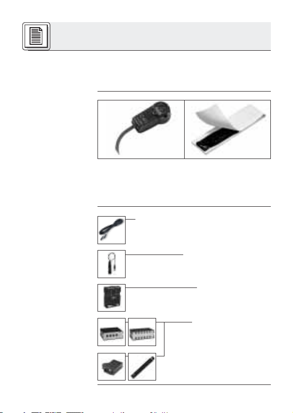
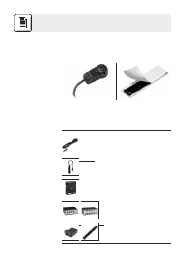
Lieferumfang
1.3 Optionales
Zubehör
Überprüfen Sie bitte, ob das Gerät, an das Sie das
Mikrofon anschließen möchten, den gültigen Sicherheitsbestimmungen entspricht und mit einer
Sicherheitserdung versehen ist.
1 C 411
III
Klebemasse
Kontrollieren Sie bitte, ob die Verpackung alle
oben angeführten Teile enthält. Falls etwas fehlt,
wenden Sie sich bitte an Ihren AKG-Händler.
• Mikrofonkabel MK 9/10: 10 m 2-polig
geschirmtes Kabel mit XLR-Stecker
und XLR-Kupplung
• Phantomspeiseadapter
MPA III L (für C 411
• Batteriespeisegerät
B 29 L (für C 411
III
III
• Phantomspeisegeräte
N 62 E, N 66 E,
B 18, B 15
(für C 411
III
PP)
L)
L)
2

1 Beschreibung
• Robuster Körperschallwandler für Instrumentalabnahme auf der Bühne.
•Frequenzgang speziell für akustische Gitarre,
Banjo, Zither und Streichinstrumente ausgelegt.
• Klebemasse für die direkte Montage am Instrument im Lieferumfang enthalten.
Der Pickup C 411
III
ist ein Körperschallwandler
und nimmt den Schall direkt von der Oberfläche
des schwingenden Resonanzkörpers eines akustischen Instruments auf.
Der Pickup wurde speziell für die direkte Montage
an akustischen Gitarren, Banjos, Zithern und
Streichinstrumenten entwickelt und garantiert eine
absolut klangtreue, unverfälschte Wiedergabe Ihres Instruments.
Die Klebemasse zur Befestigung des Pickups ist
absolut unschädlich für Holz-, Kunststoff- und
Metalloberflächen.
Der Pickup ist in zwei Ausführungen erhältlich:
• Für 9 bis 52 V Universal-Phantomspeisung.
3 m langes, fix verbundenes Anschlusskabel
mit Phantomspeiseadapter mit integriertem
3-poligem XLR-Stecker.
• Für Speisung mittels Batteriespeisegerät
B 29 L, Phantomspeiseadapter MPA III L oder
AKG.WIRELESS-Taschensender. 1,5 m langes, fix verbundenes Anschlusskabel mit
3-poligem Mini-XLR-Stecker.
1.4 Besondere
Merkmale
1.5 Kurzbeschreibung
1.6 Varianten
III
C 411
C 411
PP
III
L
3
2 Anschluss
2.1 Einleitung
Der C 411
und benötigt daher eine Stromversorgung.
III
Pickup ist ein Kondensatorwandler
Wichtig!
(
2.2 C 411
2.2.1 Anschluss
an symmetri-
sche Eingänge
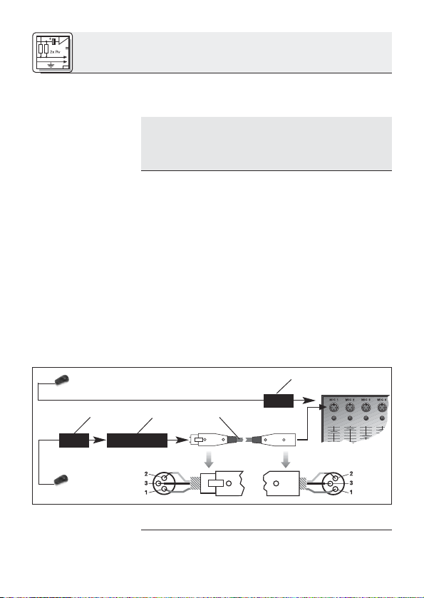
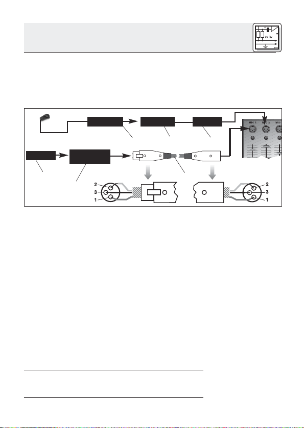
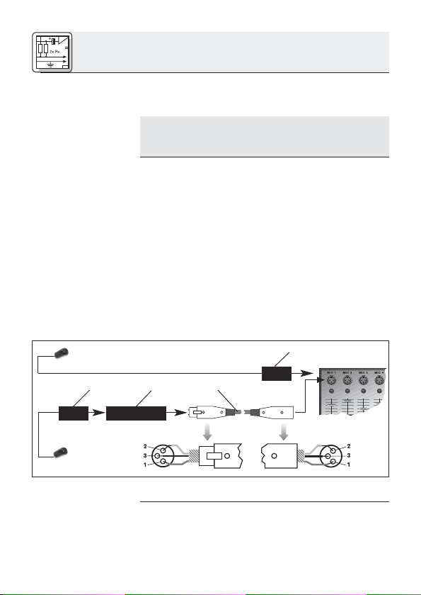
Siehe Abb. 1.
MPA
Abb. 1: Anschluss an symmetrischen Eingang
Wenn Sie andere als die von AKG empfohlenen Speisegeräte verwenden, kann der
Pickup beschädigt werden und erlischt
die Garantie.
III
PP
1. Stecken Sie den Phantomspeiseadapter (1) am
Kabel des Pickups an einen symmetrischen
XLR-Mikrofoneingang mit Phantomspeisung an.
2. Schalten Sie die Phantomspeisung ein. (Lesen
Sie dazu in der Betriebsanleitung des jeweiligen Gerätes nach.)
3. Wenn Ihr Mischpult keine Phantom-
speisung besitzt, stecken Sie den
Phantomspeiseadapter (1) an ein optionales
AKG-Phantomspeisegerät (2) (N 62 E, N 66 E,
B 18, B 15) an und verbinden Sie das
Phantomspeisegerät mit Hilfe eines XLRKabels (3) (z.B. AKG MK 9/10 - nicht mitgliefert) mit einem symmetrischen Eingang.
Phantom
MPA
4

2 Anschluss
Phantomspeisegeräte (2) von AKG können Sie auch
an einen asymmetrischen Eingang anschließen.
Verwenden Sie dazu ein Kabel (3) mit XLRStecker (weiblich) und Mono-Klinkenstecker:
PhantomMPA
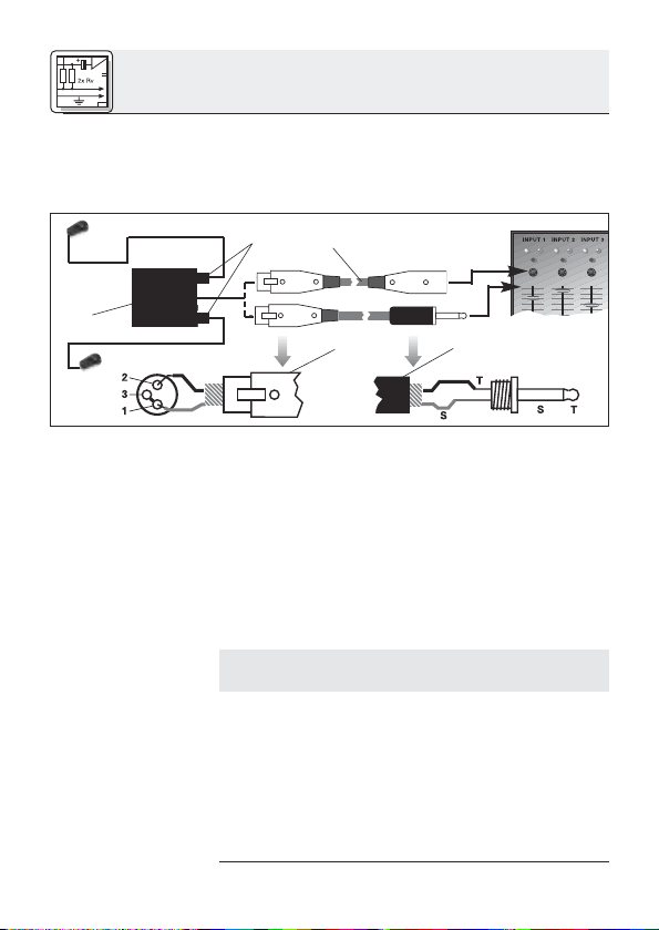
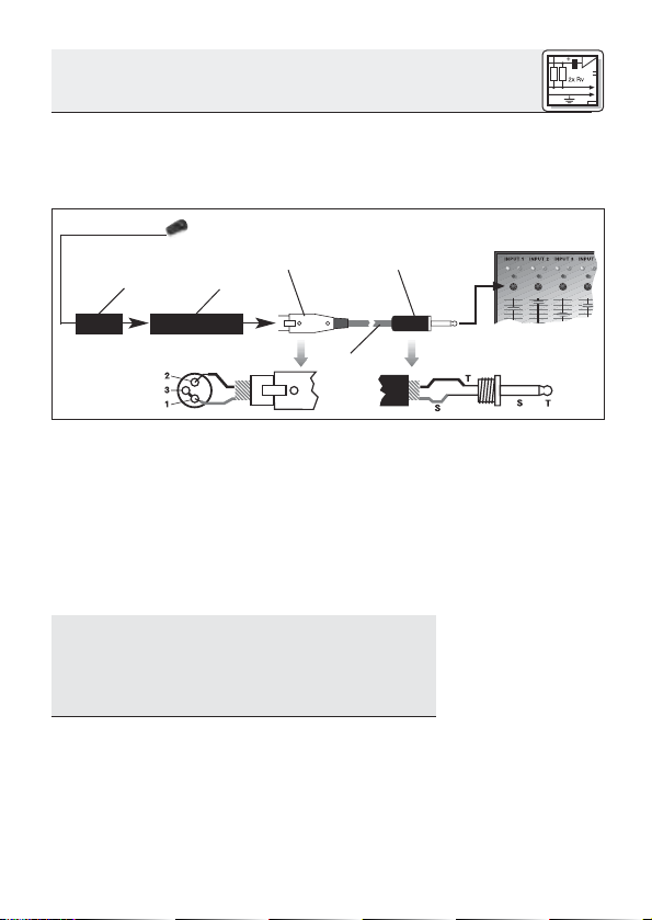
Abb. 2: Anschluss an asymmetrischen Eingang
1. Verbinden Sie im XLR-Stecker (4) mittels einer
Drahtbrücke Stift 1 mit Stift 3 und mit der
Abschirmung.
2. Verbinden Sie die innere Ader des Kabels mit
Stift 2 des XLR-Steckers (4) und der Spitze
des Klinkensteckers (5).
Beachten Sie, dass asymmetrische Kabel Einstreuungen aus Magnetfeldern (von Netz- und
Lichtkabeln, Elektromotoren usw.) wie eine Antenne aufnehmen können . Bei Kabeln, die länger als 5 m sind, kann dies zu Brumm- und
ähnlichen Störgeräuschen führen.
2.2.2 Anschluss
an asymmetrische Eingänge
Siehe Abb. 2.
Hinweis:
☞
5
2 Anschluss
2.3 C 411
2.3.1 Anschluss
mittels B 29 L
III
L
Mit dem optionalen Batteriespeisegerät B 29 L
können Sie den Pickup an symmetrische oder
asymmetrische Eingänge ohne Phantomspeisung
anschließen.
B 29 L
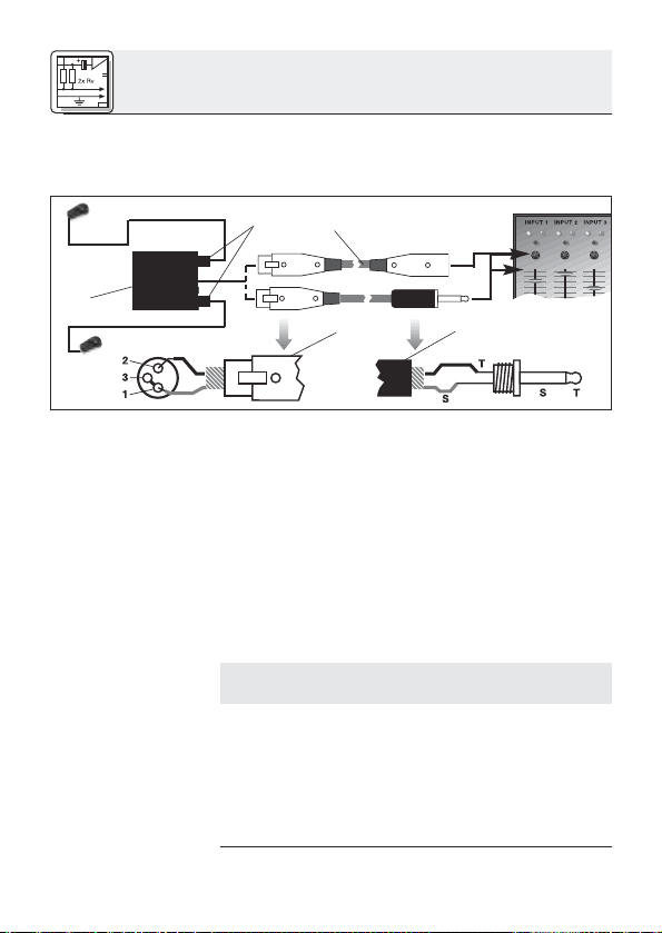
Abb. 3: Anschluss-Schema mit B 29 L
Siehe Abb. 3.
Wichtig!
(
Symmetrischer
Eingang:
Siehe Abb. 3.
Asymmetrischer
Eingang:
1. Kabel anstecken: Stecken Sie den Mini-XLR-
Stecker (1) am Kabel des Pickups bis zum
Anschlag in eine der beiden Mini-XLRBuchsen am B 29 L (2).
Der Stecker (1) verriegelt sich automatisch.
Kabel abziehen: Zum Abziehen des Kabels
drücken Sie auf den Entriegelungsknopf am
Mini XLR-Stecker (1) und ziehen Sie den
Stecker (1) aus der Buchse heraus.
Um das Kabel nicht zu beschädigen, ziehen Sie niemals am Kabel selbst!
2. Verbinden Sie das B 29 L (2) mit dem
gewünschten Eingang.
Zum Anschluss an einen symmetrischen
Eingang verwenden Sie ein handelsübliches
XLR-Kabel (3).
Siehe Kapitel 2.2.2.
6
2 Anschluss
1. Kabel anstecken: Stecken Sie den Mini-XLR-
Stecker (1) am Kabel des Pickups bis zum
Anschlag in die Mini-XLR-Kupplung (2) am
Anschlusskabel des MPA III L (3).
Der Stecker (1) verriegelt sich automatisch.
Mini XLR Mini XLR MPA
MPA
Phantom
Abb. 4: Anschluss-Schema mit MPA III L
Kabel abziehen: Siehe Kapitel 2.3.1.
2. Stecken Sie den MPA III L (3) an einen symmetrischen XLR-Mikrofoneingang mit
Phantomspeisung an.
3. Schalten Sie die Phantomspeisung ein. (Lesen
Sie dazu in der Betriebsanleitung des jeweiligen Gerätes nach.)
4. Wenn Ihr Mischpult keine Phantom-
speisung besitzt, stecken Sie den MPA III L
(3) an ein optionales AKG-Phantomspeisegerät (4) (N 62 E, N 66 E, B 18, B 15) an und
verbinden Sie das Phantomspeisegerät (4) mit
Hilfe eines XLR-Kabels (5) (z.B. AKG MK 9/10
- nicht mitgliefert) mit einem symmetrischen
Eingang.
2.3.2 Anschluss
mittels MPA III L
Siehe Abb. 4.
Siehe Abb. 4.
Lesen Sie in der Bedienungsanleitung Ihres
Taschensenders nach.
2.3.3 Anschluss an
Taschensender
7
3 Anwendung
3.1 Einleitung
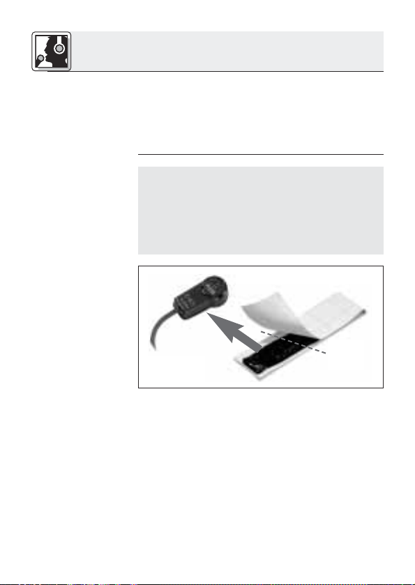
3.2 Befestigung
am Instrument
☞
Hinweis:
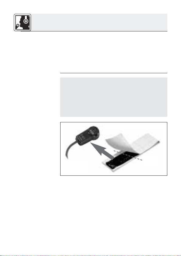
Abb. 5: Klebe-
masse auf die
Unterseite des
Pickups drücken.
Siehe Abb. 6 bis 9
auf Seite 9.
Da die Resonanzkörper akustischer Instrumente
an verschiedenen Punkten in unterschiedlicher
Weise schwingen, können Sie durch Variieren des
Schallabnahmepunkts verschiedene Klangfarben
erhalten.
Bewährte Positionierungen und weitere Anwendungshinweise finden Sie in Kapitel 3.2.
Wenn Sie den Pickup auf einer lackierten Oberfläche befestigen wollen, kontrollieren Sie vorher
den Zustand des Lacks.
Auf porösem, brüchigem Lack ist die Haltekraft
der Klebemasse geringer und es besteht die Gefahr, dass die Klebemasse beim Entfernen des
Pickups die Lackschicht weiter beschädigt.
✂
1. Ziehen Sie die Schutzfolie von der mitgelieferten Klebemasse ab.
2. Drücken Sie einen Teil der Klebemasse (etwa
gleich groß wie der Pickup) auf die Unterseite
des Pickups.
3. Drücken Sie den Pickup auf den Steg oder in
der Nähe des Stegs auf die Decke des Instruments.
8
3 Anwendung
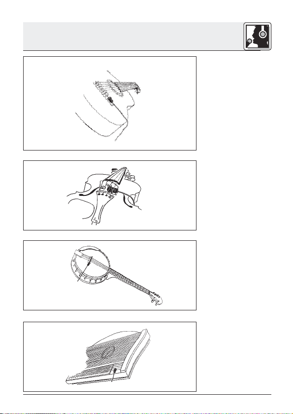
Abb. 6: Gitarre
Abb. 7: Violine
Abb. 8: Banjo
Abb. 9: Zither
9

5 Fehlerbehebung
Fehler
Kein Ton:
Verzerrungen:
Mögliche Ursache
1. Mischpult und/oder
Verstärker ausgeschaltet.
2. Kanal-Fader oder
Summenpegelregler
am Mischpult oder
Lautstärkeregler des
Verstärkers steht auf
Null.
3. Pickup nicht an
Mischpult oder
Verstärker angeschlossen.
4. Kabelstecker nicht
richtig angesteckt.
5. Kabel defekt.
6. Keine Speisespannung.
1. Gain-Regler am
Mischpult zu weit
aufgedreht.
2. Mischpulteingang zu
empfindlich.
Abhilfe
1. Mischpult und/oder
Verstärker einschalten.
2. Kanal-Fader oder
Summenpegelregler
am Mischpult oder
Lautstärkeregler des
Verstärkers auf gewünschten Pegel
einstellen.
3. Pickup an Mischpult
oder Verstärker anschließen.
4. Kabelstecker
nochmals anstecken.
5. Kabel überprüfen
und falls nötig ersetzen.
6. Phantomspeisung
einschalten.
Phantomspeisegerät: ans Netz
anschließen bzw.
Batterie(n) einlegen.
Kabel überprüfen
und falls nötig ersetzen.
1. Gain-Regler zurückdrehen.
2. 10-dB-Vorabschwächung
zwischen Pickupkabel und Eingang
stecken.
10
6 Technische Daten
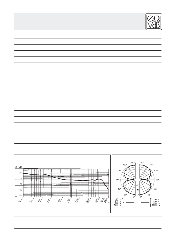
Arbeitsweise: Kondensatorwandler mit Permanentladung
Richtcharakteristik: Achter
Übertragungsbereich: 10 – 18.000 Hz
Empfindlichkeit: 1 mV/ms-2(Körperschallwandler)
Elektrische Impedanz bei 1000 Hz: 200 Ω asymmetrisch
Empfohlene Lastimpedanz: ≥1000 Ω
Grenzschalldruck für 1 % / 3% Klirrfaktor: 96 dB / 103 dB
Speisespannung: C 411
Stromaufnahme: ca. 2,2 mA
Kabellänge/Steckerart: C 411
Oberfläche: mattschwarz
Abmessungen: 27 x 14 x 9,5 mm
Netto/Bruttogewicht: C 411
Dieses Produkt entspricht der Norm EN 500-82/1, vorausgesetzt, dass nachgeschaltete Geräte CE-konform sind.
Frequenzgang Polardiagramm
III
PP: 9–52 V Phantomspeisung
III
L: Batteriespeisegerät B 29 L,
C 411
Phantomspeiseadapter MPA III L, AKG
WMS Taschensender
III
PP: 3 m / XLR 3-polig
III
C 411
L: 1,5 m / Mini-XLR 3-polig
III
PP: 98 g / 225 g
III
C 411
L: 18 g / 150 g
Reinigung: Reinigen Sie das Gehäuse des Pickups mit einem mit Wasser befeuchteten Tuch.
11
1 Precaution/Description
1.1 Precaution
1.2 Unpacking
1.3 Optional
Accessories
Please make sure that the piece of equipment
your pickup will be connected to fulfills the safety
regulations in force in your country and is fitted
with a ground lead.
1 C 411
III
Adhesive compound
Check that the packaging contains all of the components listed above. Should anything be missing, please contact your AKG dealer.
• MK 9/10 microphone cable: 10-m
(30-ft.) 2-conductor shielded cable
w/male and female XLR connectors
• MPA III L phantom power adapter
(for C 411
• B 29 L battery power supply
(for C 411
III
III
• N 62 E, N 66 E, B 18, B15
phantom power suppplies
(for C 411
III
PP)
L)
L)
12

1 Description
• Rugged vibration pickup for instrument miking
on stage.
•Frequency response tailored to acoustic guitar,
banjo, zither, and bowed string instrument miking.
• Complete with adhesive compound for mounting the pickup directly on the instrument.
The C 411
III
is a vibration pickup that converts the
vibrations of an instrument’s soundboard into an
electrical signal.
The C 411
III
has been specifically designed for
direct attachment to an acoustic guitar, banjo,
zither, or bowed string instrument and ensures
absolutely accurate, coloration-free reproduction.
The supplied adhesive compound for attaching
the pickup will leave wooden, plastic, and metal
surfaces untainted.
The C 411
III
is available in two versions:
• For 9 to 52 V universal phantom power. 10-ft.
(3-m) permanently attached connecting cable
with phantom power adapter with integrated
3-pin XLR connector.
• For use with the B 29 L battery power supply,
MPA III L phantom power adapter, or
AKG.WIRELESS bodypack transmitters. 5-ft.
(1.5-m) permanently attached connecting cable with 3-pin mini XLR connector
1.4 Features
1.5 Brief
Description
1.6 Versions
III
C 411
C 411
PP
III
L
13
2 Interfacing
2.1 Introduction
The C 411
therefore needs a power supply.
III
pickup is a condenser transducer and
Important!
(
2.2 C 411
2.2.1 Connecting
to Balanced
Inputs
Refer to fig. 1.
MPA
Fig. 1: Connecting to a balanced input.
Using any power supply other than those
recommended by AKG may damage your
pickup and will void the warranty.
III
PP
1. Connect the phantom power adapter (1) on the
pickup cable to a balanced XLR microphone
input with phantom power.
2. Switch the phantom power on. (Refer to the instruction manual of the unit to which you
connected your pickup.)
3. If your mixer provides no phantom power:
Connect the phantom power adapter (1) to an
optional AKG phantom power supply (2) (N 62 E,
N 66 E, B 18, B 15) and use an XLR cable (3)
(e.g., an optional MK 9/10 from AKG) to connect
the phantom power supply to the desired
balanced input.
Phantom
MPA
14
2 Interfacing
You may connect any AKG phantom power supply (2) to an unbalanced input, too.
Use a cable (3) with a female XLR connector and
TS jack plug:
PhantomMPA
Fig. 2: Connecting to an unbalanced input.
1. On the XLR connector (4), use a wire bridge to
connect pin 1 to pin 3 and the cable shield.
2. Connect the inside wire of the cable to pin 2
on the XLR connector (4) and the tip contact
of the jack plug (5).
3. Connect the shield of the cable to the shaft
contact on the jack plug (5).
Unbalanced cables may pick up interference
from stray magnetic fields near power or lighting
cables, electric motors, etc. like an antenna.
This may introduce hum or similar noise if you
use a cable that is longer than 16 feet (5 m).
2.2.2 Connecting
to Unbalanced
Inputs
Refer to fig. 2.
Note:
☞
15
2 Interfacing
2.3 C 411
2.3.1 Using the
Optional B 29 L
III
L
The optional B 29 L battery supply allows you to
connect the pickup to balanced or unbalanced
inputs with no phantom power.
B 29 L
Fig. 3: Using the B 29 L to power the microphone.
Refer to fig. 3.
Important!
(
Refer to fig. 3.
Balanced input:
Unbalanced input:
1. Connecting the cable: Push the mini XLR
connector (1) on the pickup cable into one of
the two mini XLR sockets on the B 29 L (2) to
the stop.
The connector will lock automatically.
Disconnecting the cable: To disconnect the
cable, press the unlocking button on the mini
XLR connector (1) and pull the connector (1)
out of the socket.
To avoid damaging the cable, never try to
pull out the cable itself!
2. Connect the B 29 L (2) to the desired input.
•Use a commercial XLR cable (3) to connect
• Refer to section 2.2.2 above.
the B 29 L (2) to a balanced input.
16

2 Interfacing
1. Connecting the cable: Push the mini XLR
connector (1) on the pickup cable into the mini
XLR socket (2) on the cable of the MPA III L (3)
to the stop.
The connector will lock automatically.
Mini XLR Mini XLR MPA
MPA
Phantom
Fig. 4: Connection diagram with MPA III L.
Disconnecting the cable: Refer to section
2.3.1 above.
2. Connect the MPA III L (3) to a balanced XLR
microphone input with phantom power.
3. Switch the phantom power on. (Refer to the instruction manual of the unit to which you
connected your pickup.)
4. If your mixer provides no phantom power:
Connect the MPA III L (3) to an optional AKG
phantom power supply (4) (N 62 E, N 66 E, B 18,
B 15) and use an XLR cable (5) (e.g., an optional
MK 9/10 from AKG) to connect the phantom
power supply (4) to the desired balanced input.
2.3.2 Using the
MPA III L
Refer to fig. 4.
Refer to fig. 4.
Refer to the manual of your bodypack transmitter.
2.3.3 Connecting
to a Bodypack
Transmitter
17
3 Use
3.1 Introduction
3.2 Attaching
the Pickup to
the Instrument
☞
Note:
Fig. 5: Pressing the
adhesive com-
pound on the
underside of the
pickup.
Refer to figs. 6
through 9
on page 19.
Since a soundboard vibrates differently in different
places, you can get diferent sounds by carefully
selecting the spot where you mount the pickup.
Section 3.2 describes proven techniques that you
may want to use as starting points for your own
experiments.
If you are going to attach the pickup to a lacquered surface, check the condition of the lacquer
coat first.
If the lacquer coat is porous or cracked, the adhesive compound will lose some of its tack and
may damage the lacquer coat further when you remove the pickup.
✂
1. Remove the backing from the supplied adhesive compound.
2. Press some of the adhesive compound (just
enough to cover the "footprint" of the pickup)
on the underside of the pickup.
3. Press the pickup onto the bridge of your instrument or onto the soundboard, near the bridge.
18

3 Use
Fig. 6: Guitar
Fig. 7: Violin
Fig. 8: Banjo
Fig. 9: Zither
19

5 Troubleshooting
Problem
No sound:
Distortion:
Possible Cause
1. Power to mixer
and/or amplifier is
off.
2. Channel or master
fader on mixer, or
volume control on
amplifier is at zero.
3. Pickup is not
connected to mixer or amplifier.
4. Cable connectors
are seated loosely.
5. Cable is defective.
6. No supply voltage.
1. Gain control on
the mixer set too
high.
2. Mixer input sensitivity too high.
Remedy
1. Switch power to
mixer or amplifier
on.
2. Set channel or
master fader on
mixer or volume
control on amplifier to desired
level.
3. Connect pickup to
mixer or amplifier.
4. Check cable
connectors for secure seat.
5.
Check cable and replace if damaged.
6. Switch phantom
power on.
Phantom power
supply: connect to
power outlet or insert battery
(batteries).
Check cable and replace if necessary.
1. Turn gain control
down CCW.
2. Connect a 10-dB
preattenuation
pad between
pickup cable and
input.
20
 Loading...