

Page 1
C214
BEDIENUNGSANLEITUNG . . . . . . . . . .S. 2
Bitte vor Inbetriebnahme des Gerätes lesen!
USER INSTRUCTIONS . . . . . . . . . . . . . . .p. 16
Please read the manual before using the equipment!
MODE D’EMPLOI . . . . . . . . . . . . . . . . . . . . .p. 30
Veuillez lire cette notice avant d’utiliser le système!
ISTRUZIONI PER L’USO . . . . . . . . . . . . .p. 44
Prima di utilizzare l’apparecchio, leggere il manuale!
MODO DE EMPLEO . . . . . . . . . . . . . . . . . . .p. 58
¡Sirvase leer el manual antes de utilizar el equipo!
INSTRUÇÕES DE USO . . . . . . . . . . . . . . .S. 72
Favor leia este manual antes de usar o equipamento!
Page 2

Inhaltsverzeichnis
Seite
Sicherheitshinweis ..................................................................................................3
1 Beschreibung ....................................................................................................3
1.0 Einleitung .....................................................................................................3
1.1 Lieferumfang ................................................................................................3
1.2 Optionales Zubehör .......................................................................................3
1.3 Kurzbeschreibung .........................................................................................3
1.4 Bedienelemente............................................................................................4
2 Stromversorgung...............................................................................................5
3 Anwendungshinweise .......................................................................................6
3.1 Einleitung .....................................................................................................6
3.2 Tiefenabsenkung...........................................................................................6
3.3 Vorabschwächung.........................................................................................6
3.4 Montage am Stativ ........................................................................................6
3.5 Aufstellungstipps ..........................................................................................6
3.5.1 Solostimme..........................................................................................7
3.5.2 Chor/Begleitchor ..................................................................................8
3.5.3 Violine, Viola.........................................................................................8
3.5.4 Kontrabass, Violoncello.........................................................................9
3.5.5 Akustische Gitarre ................................................................................9
3.5.6 Querflöte ...........................................................................................10
3.5.7 Klarinette...........................................................................................10
3.5.8 Tenor-/Sopransaxophon ......................................................................10
3.5.9 Trompete/Posaune .............................................................................11
3.5.10 Flügel/Pianino ..................................................................................11
3.5.11 E-Gitarre/E-Bass ..............................................................................12
3.5.12 Schlagzeug......................................................................................12
4 Reinigung ........................................................................................................13
4.1 Mikrofon.....................................................................................................13
4.2 Windschutz.................................................................................................13
5 Technische Daten ............................................................................................14
2 C 214
Page 3

Sicherheitshinweis
L
• Überprüfen Sie bitte, ob das Gerät, an das Sie das Mikrofon anschließen
möchten, den gültigen Sicherheitsbestimmungen entspricht und mit einer Sicherheitserdung versehen ist.
1 Beschreibung
Vielen Dank, dass Sie sich für ein Produkt aus dem Hause AKG entschieden haben. Bitte lesen Sie die Bedienungsanleitung aufmerksam durch, bevor Sie
das Gerät benützen, und bewahren Sie die Bedienungsanleitung sorgfältig auf,
damit Sie jederzeit nachschlagen können. Wir wünschen Ihnen viel Spaß und Erfolg!
• Mikrofon C 214
• Elastische Mikrofonaufhängung H 85
• Schaumstoff-Windschutz W 214
• Hochwertiger Transportkoffer für Mikrofon und mitgeliefertes Zubehör
• Kontrollieren Sie bitte, ob die Verpackung alle oben angeführten Teile enthält.
Falls etwas fehlt, wenden Sie sich bitte an Ihren AKG-Händler.
• Optionales Zubehör finden Sie im aktuellen AKG-Katalog/Folder oder auf
www.akg.com. Ihr Händler berät Sie gerne.
Die Konstruktion dieses Großmembran-Kondensatormikrofons stützt sich auf die
Erfahrungen, die mit den Modellen C 12, C 12A, C 414 EB, C 414 B-ULS, C 414 BTL II sowie C 414 XL II im langjährigen Studiobetrieb weltweit gemacht wurden.
Basierend auf handselektierten modernen und zuverlässigen Bauteilen und fortschrittlichen Produktionsprozessen wird das Mikrofon höchsten professionellen
Anforderungen gerecht und wird auch einem langzeitigen anspruchsvollen Studioeinsatz standhalten.
Die Elektronik des Mikrofons wurde neu überarbeitet, wobei größter Wert auf maximale Dynamik und Linearität gelegt wurde. Das geringe Eigenrauschen und der
hohe Aussteuerungsbereich garantieren einen Dynamikbereich von 143 dB (Abewertet).
Die Wandlerkapsel ist in moderner Backplate-Technologie aufgebaut und besitzt
eine einseitig goldbedampfte Membrane. Diese Bauweise verhindert auch bei
höchsten Schalldrücken örtliche Kurzschlüsse zur Gegenelektrode.
Das Ganzmetallgehäuse wirkt sehr gut gegen mögliche HF-Einstreuungen, wenn
Sie das Mikrofon in Sendernähe oder gemeinsam mit drahtlosen Mikrofonen oder
sonstigen Kommunikationsanlagen verwenden.
!
L
1.0 Einleitung
1.1 Lieferumfang
1.2 Optionales
Zubehör
1.3 Kurzbeschreibung
3C 214
Page 4
1 Beschreibung
1.4 Bedien elemente Das C 214 bietet je einen Wahlschalter für Vorabschwächung und Tiefenabsenkung.
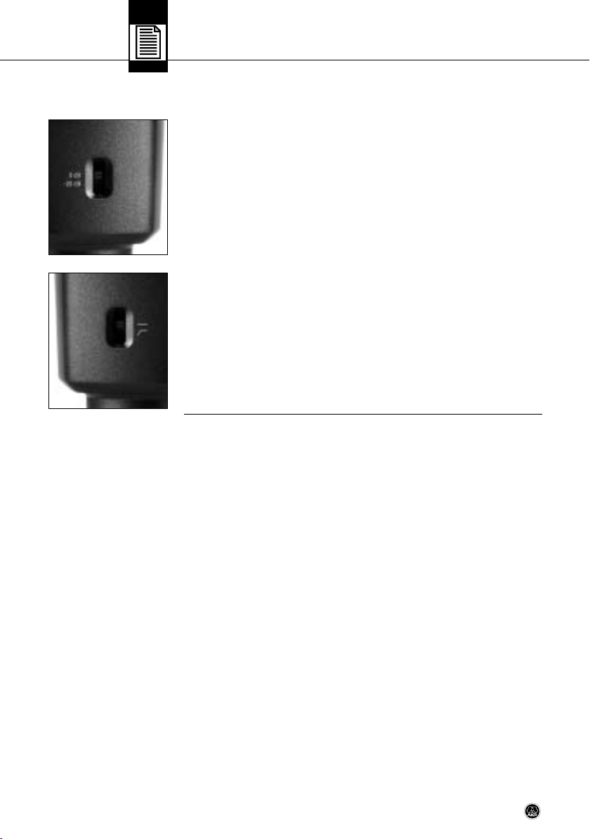
1 Wahlschalter für Vorabschwächung
Der Wahlschalter 1 an der linken Seite des Mikrofons (siehe Abb. 1) erlaubt Ihnen,
die Aussteuerungsgrenze um 20 dB hinaufzusetzen, um verzerrungsfreie Aufnahmen auch sehr lauter Schallquellen sowie im Nahbereich von Schall quellen machen zu können. Diese Vorabschwächung verhindert, dass der Ausgangspegel des
Mikrofons besonders bei tiefen Frequenzen kritische Aus steuerungsgrenzen von
Kleinsttransformatoren, die z.B. in Mischpulteingängen verwendet werden, überschreitet.
Abb. 1: Wahlschalter für Vorabschwächung
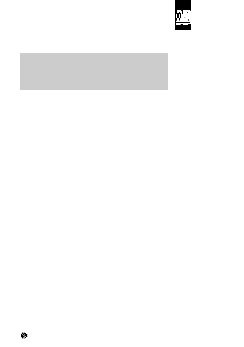
2 Wahlschalter für Tiefenabsenkung
Rumpel- oder Windgeräusche usw. können bei tiefsten Frequenzen Verzerrungen
verursachen. Die schaltbare Tiefenabsenkung (siehe Abb. 2) reduziert diese Verzerrungen zusätzlich. Die Steilheit des Filters beträgt 6 dB/Oktave bei einer Eckfrequenz von 160 Hz. Die Tiefenabsenkung wirkt auch dem Naheffekt entgegen, der
bei geringen Mikrofon abständen (weniger als 15 cm) zur Schallquelle auftreten
kann.
Abb. 2: Wahlschalter für Tiefenabsenkung
4 C 214
Page 5
2 Stromversorgung
Das C 214 zeichnet sich durch niedriges Eigenrauschen (nur 13 dB(A)!) und gleichzeitig hohe Übersteuerungsfestigkeit aus. Dieses Mikrofon benötigt eine Phantomspeisung von 12 bis 52 V nach IEC 61938.
• Verbinden Sie das Mikrofon ausschließlich mit Phantom speisequellen
(Eingang mit Phantomspeisung oder externes Phantomspeisegerät)
nach IEC mit erdfreiem Anschluss und verwenden Sie dazu ausschließlich ein symmetrisches Kabel mit Studiosteckverbindern nach
IEC 268-12. Nur so kann ein sicherer und problemloser Betrieb garantiert werden.
!
L
Wichtig!
5C 214
Page 6
3 Anwendungshinweise
3.1 Einleitung
3.2 Tiefenabsenkung
3.3 Vor abschwächung
3.4 Montage am Stativ
Neben der hohen Aussteuerbarkeit bei geringsten Verzerrungen und der temperatur- und feuchtigkeitssicheren Konstruktion bietet das Mikrofon einmalige universelle Anwendbarkeit.
Der ausgeglichene Frequenzverlauf orientiert sich an dem für AKG-Großmembran-Mikrofone typischen Klangcharakter.
Das C 214 können Sie sowohl im Studio als auch auf der Bühne für die meisten
Musikinstrumente einsetzen (siehe auch Kapitel 3.5). Mit seiner nierenförmigen
Richtcharakteristik eignet es sich für viele verschiedene Aufnahmesituationen,
insbesondere Nahfeldmikrofonierung.
Die schaltbare Tiefenabsenkung erlaubt Ihnen, "akustische Störquellen" wie z.B.
Luftströmungen von Klimaanlagen oder tieffrequente Vibrationen infolge von Bodenschwingungen, Hantierungs geräuschen usw. wirksam auszublenden, ohne
den Klang charakter des/der aufzunehmenden Instruments/Stimme zu verändern.
Mit der schaltbaren 20-dB-Vorabschwächung können Sie die akustische Aussteuerbarkeit des Mikrofons von 136 auf 156 dB SPL erhöhen. Achten Sie jedoch darauf, dass der maximale Pegel am Ausgang des Mikrofons von den nachgeschalteten Geräten (Mikrofon vorverstärker, Mischpulteingängen, Eingängen von Aufnahme geräten) verzerrungsfrei verarbeitet werden kann.
• Die mitgelieferte elastische Aufhängung H 85 besitzt einen Standard-3/8"Gewindeeinsatz. Damit können Sie das Mikrofon auf nahezu allen handelsüblichen Stativen und Aufhängungen mit 3/8"-Gewinde montieren.
• Zur Montage auf Stativen mit 5/8"-Gewinde entfernen Sie den Gewindeeinsatz
und schrauben Sie die elastische Halterung direkt auf das Stativ.
• Um die elastische Halterung vom Mikrofon abzunehmen, drehen Sie die bajonettähnliche Sicherung am unteren Ende der Halterung gegen den Uhrzeigersinn, um die Sicherung zu öffnen.
3.5 Aufstellungstipps
Tabelle 1: Empfohlene
Anwendungen
6 C 214
Wir empfehlen das C 214 für folgende Anwendungen:
Aufnahmequelle Studio Bühne
Lead/Solo Vocals • •
Backing Vocals/Chor • • • •
Sprache • •
Akust. Gitarre • • • •
E-Gitarre • • • •
E-Bass • •
Kontrabass • • • •
Violine • • •
Cello • • •
Zither • • •
Flügel (klassische Musik) • • • •
Page 7

3 Anwendungshinweise
Aufnahmequelle Studio Bühne
Klavier (Rock&Jazz) • • • •
Orgel • • •
Trompete • • • •
Posaune • • •
Horn • • • •
Tuba • • •
Saxophon • • • •
Querflöte • • • •
Klarinette • • • •
Bass Drum • • •
Tom s • •
Becken • • • •
Bongos, Congas • • • •
• • Besonders empfohlen
• Empfohlen
Als Einstieg in die "Wissenschaft der Aufnahmetechnik" finden Sie im folgenden
einige bewährte Mikrofonaufstellungen.
Tabelle 1 (Forts.)
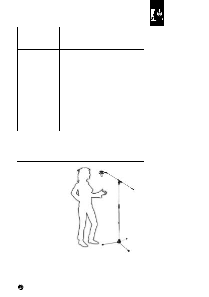
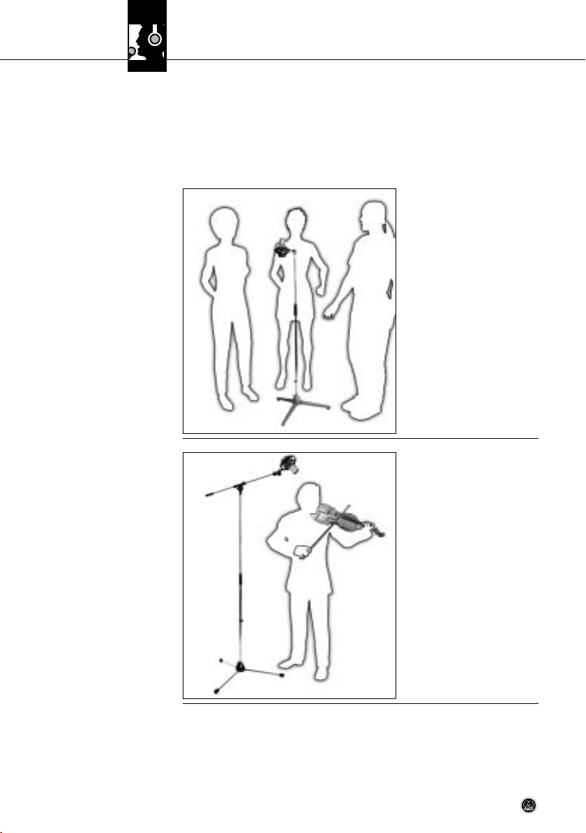
• Mikrofonabstand: 15 bis
30 cm
• Tiefenabsenkung: ein
• Für optimale Ergebnisse
empfehlen wir, einen Popschutz, z.B. PF 80 von AKG,
aufzustellen. Falls kein
Popschutz zur Hand ist,
können Sie auch den mitgelieferten Windschutz
W 214 verwenden.
• Wir empfehlen, während
der Aufnahme dem/der Sänger/in bzw. dem/der Sprecher/in zur besseren Kon trolle der eigenen Stimme
seine eigene Spur im Kopfhörer zu zumischen.
3.5.1 Solostimme
Abb. 3: Solosängerin
7C 214
Page 8

3 Anwendungshinweise
3.5.2 Chor/Begleitchor
Siehe Kapitel 3.5.1
Solostimme.
Abb. 4: Begleitchor mit
einem Mikrofon
3.5.3 Violine, Viola
Für große Chöre empfehlen wir ein Mikrofonpaar sowie je ein Stützmikrofon für
Sopran, Alt, Tenor und Bass.
In akustisch optimalen Räumen können Sie gerade mit nur zwei hochwertigen Mikrofonen hervorragende Ergebnisse erzielen.
Begleitchor/Variante 1: Falls genügend Spuren vorhanden sind, empfehlen wir,
jede Stimme einzeln nacheinander aufzunehmen.
Begleitchor/Variante 2:
Wenn Sie mit einer oder zwei
Spuren auskommen müssen,
verwenden Sie je ein Mikrofon
für zwei oder maximal drei Personen. Platzieren Sie den Chor
in einem Halbkreis vor dem Mikrofon.
Solovioline:
Richten Sie das Mikro fon aus
einer Höhe von 1,8 bis 2,5 m
auf die F-Löcher aus.
Große Streicher grup pen:
Verwenden Sie ein Mikrofonpaar in XY-, ORTF- oder anderer Anordnung, kombiniert mit
Stütz mikro fo nen im Nah bereich.
Viola:
Richten Sie das Mikro fon aus
einer Höhe von 2,2 bis 3 m auf
die F-Löcher aus.
Abb. 5: Violine
8 C 214
Page 9
3 Anwendungshinweise
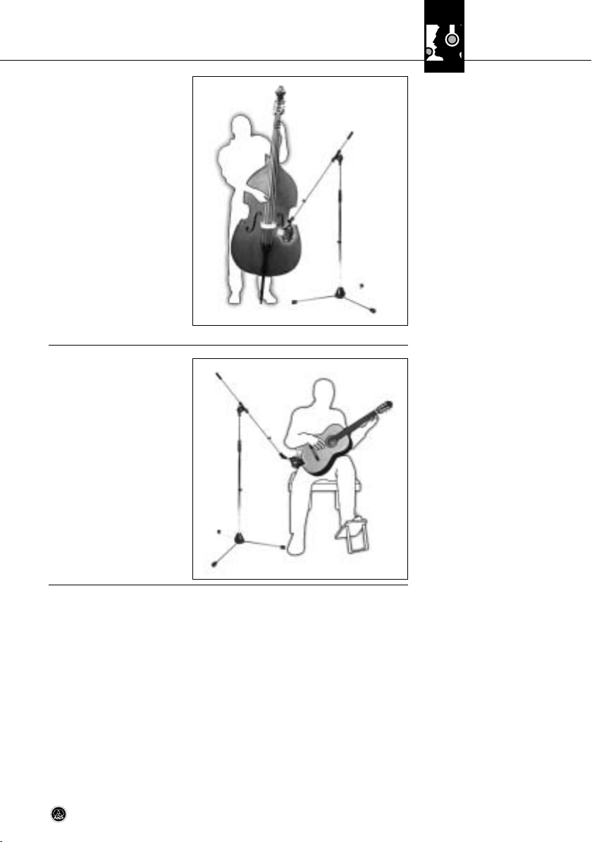
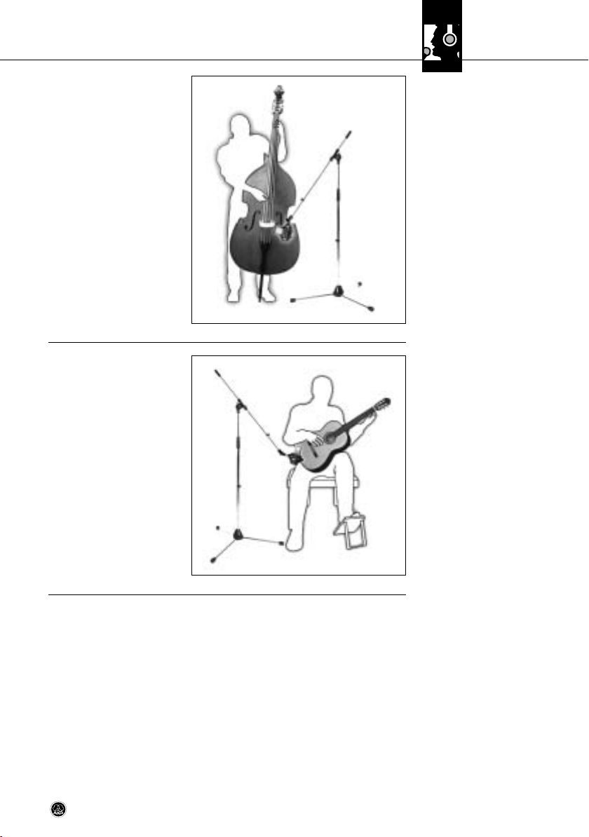
Kontrabass:
Richten Sie das Mikro fon aus
einer Entfernung von ca. 40 cm
auf eines der F-Löcher. Falls
Sie den Kontrabass gleich zeitig
mit einem Ensemble aufnehmen müssen, verringern Sie
den Abstand, um Übersprechen anderer Instru mente in
das Mikrofon zu vermeiden.
Violoncello/Variante 1:
Siehe Kontrabass.
Violoncello/Variante 2:
Nahbereichsmikrofon wie Variante 1 plus Raummikrofon. Pegel des Nahbereichsmikrofons
ca. 20 dB niedriger als Pegel des Raummikrofons einstellen.
Siehe Abb. 7.
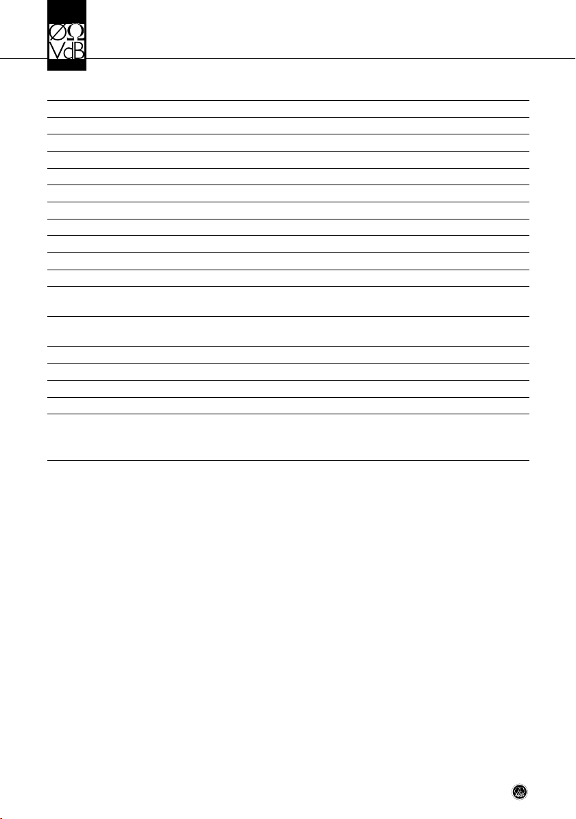
Richten Sie das C 214 im Abstand von 50 cm bis 1 m schräg
auf den Bereich zwischen Schallloch und Hals aus.
Zur besonders exakten Gestaltung des Sounds empehlen wir,
zwei Mi krofone zu verwenden:
Richten Sie ein C 214 aus einer
Entfernung von 30 bis 60 cm
auf das Schallloch aus. Lassen
Sie ein Kleinmembran mikrofon
(z.B. C 451B) aus ca. 50 cm bis
1 m Entfernung auf den Bereich zwischen Schallloch und
Hals zeigen.
3.5.4 Kontrabass,
Violoncello
Abb. 6: Kontrabass
3.5.5 Akustische Gitarre
Abb. 7: Akustische Gitarre
mit einem C 214
9C 214
Page 10

3 Anwendungshinweise
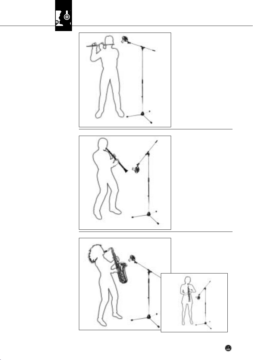
3.5.6 Querflöte
Abb. 8: Abnahme der
Querflöte mit nur einem
Mikrofon
3.5.7 Klarinette
Wir empfehlen, zwei Mi krofone
zu verwenden.
Richten Sie Mikrofon 1 schräg
von oben auf den Mund des
Spielers (wenig Anblasgeräu sche), Mikro 2 seitlich auf das
Instrument.
Abnahme mit nur einem Mikrofon: Wie Mikrofon 1, in ca. 2 m
Abstand, 2 bis 2,5 m über dem
Fuß boden.
Richten Sie das Mikro fon auf
die letzte untere Klappe. Um
Klappen geräusche zu minimieren, stellen Sie das Mi krofon
etwas seitlich vom Instrument
auf.
Abb. 9: Klarinette
3.5.8 Tenor/
Sopransaxophon
Abb. 10: Tenorsaxophon (a),
Sopransaxophon (b)
10 C 214
Richten Sie das Mikro fon aus
a
einer Entfernung von ca. 50 cm
bis 1 m auf die Mitte des Instru ments aus.
b
Page 11

3 Anwendungshinweise
Stellen Sie das Mikrofon ca.
30 cm vor dem In strument, etwas außerhalb der Achse des
Schallbechers, auf. Schal ten
Sie am Mikro fon die Vorabschwäch ung ein. Der mitgelieferte Windschutz hilft, Blasgeräusche zu reduzieren.
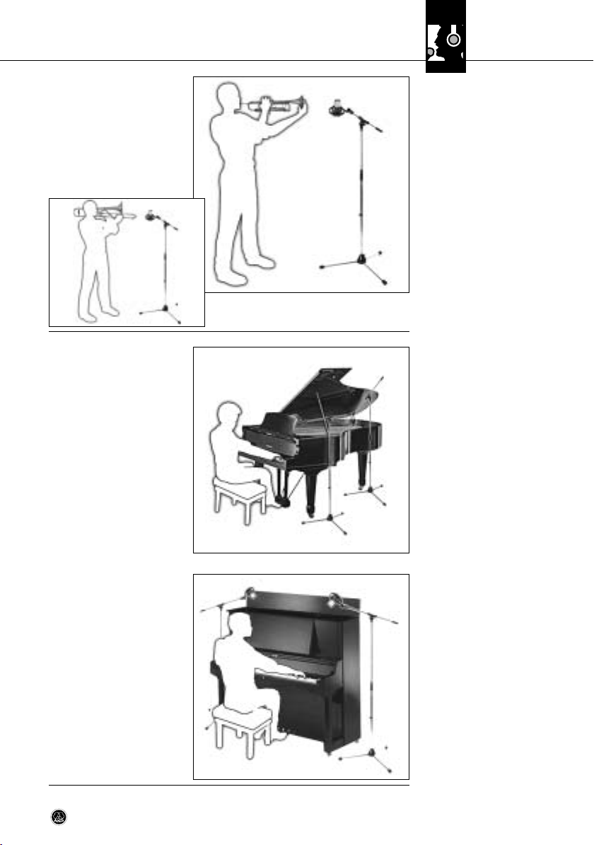
Flügel:
Richten Sie ein C 214 oder zwei
C 214 in XY- oder ORTF-Anord nung aus einer Höhe von 1,5
bis 2 m auf die mittleren Saiten
aus.
Für Rock/Pop-Sounds verwenden Sie zwei C 214, ca.
20-40 cm über den Saiten.
Richten Sie Mikro 1 auf den
Diskant bereich, Mikro 2 auf
den Bassbereich jeweils ca.
15 cm hinter den Dämpfern.
3.5.9 Trompete/Posaune
a
b
Abb. 11: Trompete (a),
Posaune (b)
3.5.10 Flügel/Pianino
Pianino:
Abnahme wie Flügel. Öffnen
Sie den Deckel und lassen Sie
die Mikrofone von oben "in das
Instru ment schauen".
Abb. 12: Flügel
Abb. 13: Pianino
11C 214
Page 12

3 Anwendungshinweise
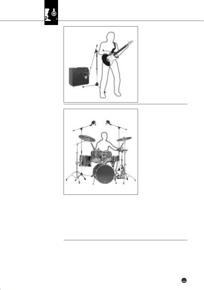
3.5.11 E-Gitarre/E-Bass
Abb. 14: E-Gitarre
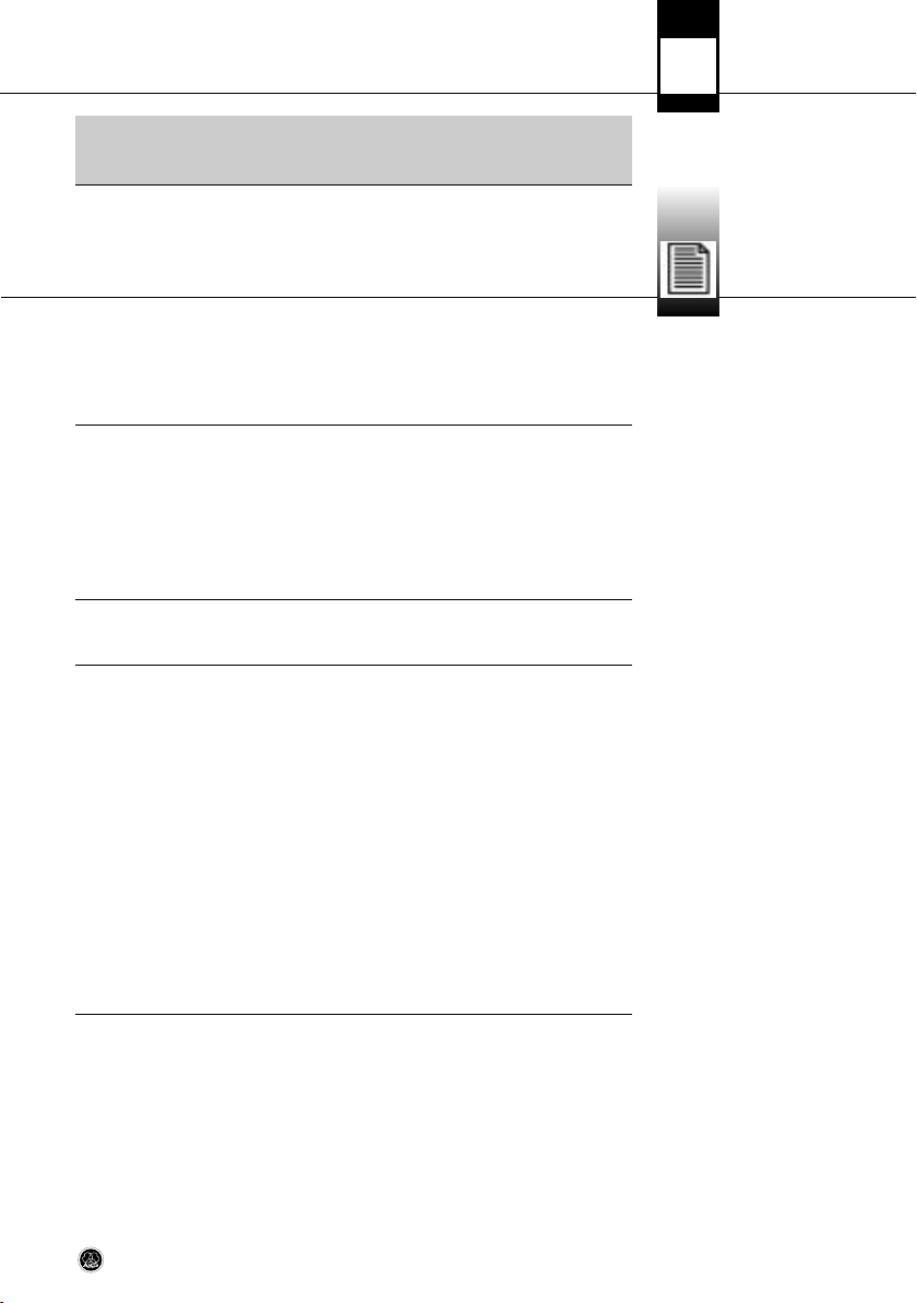
3.5.12 Schlagzeug
Abb. 15: Schlagzeug
E-Gitarre:
Stellen Sie das Mikrofon in einem Abstand von 8-15 cm
leicht außerhalb der Mitte der
Laut sprechermembran auf. Aktivieren Sie Tiefenab senkung
und Vorab schwächung. Eventuell ein zweites Raum mikro fon
einsetzen.
E-Bass:
Wie E-Gitarre. Sie können zusätzlich das direkte Signal vom
Line-Ausgang des Bassverstärkers über eine DI-Box zum Mikrofon signal mischen.
Overhead-Abnahme:
Positionieren Sie zwei C 214 in
AB- oder XY-Anordnung 80 cm
bis 120 cm über dem Kopf des
Schlagzeugers. Die se Technik
liefert ein sehr natürliches
Klang-bild des gesamten
Schlagzeugs (wenig oder gar
keine Entzerrung/Klangregelung einsetzen!).
Hänge-Toms und FloorToms:
Richten Sie aus einer Entfernung von 5 bis 10 cm ein Mikrofon pro Tom oder je ein Mikrofon zwischen zwei Toms auf
den Rand des Schlagfells aus.
Um Übersprechen von anderen Instrumenten zu reduzieren, senken Sie am
Mischpult die Höhen über 10 kHz ab.
Bassdrum:
• Aktivieren Sie unbedingt die Vorabschwächung (-20 dB), da die Bassdrum ex-
trem hohe Schallpegel erzeugen kann.
• Positionieren Sie das Mikrofon direkt im Kessel.
Für einen sehr trockenen Klang (“Click”) mit viel Attacke platzieren Sie das Mikrofon in einem Winkel von 45° nahe am Schlagfell.
Für einen Klang mit mehr Bauch positionieren Sie das Mikrofon näher beim
Resonanzfell oder bis zu 15 cm außerhalb der Öffnung des Resonanzfells.
12 C 214
Page 13

4 Reinigung
• Reinigen Sie die Gehäuseoberfläche des Mikrofons mit einem mit Wasser befeuchteten Tuch.
• Waschen Sie den Schaumstoff-Windschutz mit Seifenwasser. Der Windschutz
ist sofort nach dem Trocknen wieder einsatzbereit.
4.1 Mikrofon
4.2 Windschutz
13C 214
Page 14
5 Technische Daten
Arbeitsweise: 25 mm-Großmembransystem nach Druckgra-
Richtcharakteristik: Niere
Leerlauf-Übertragungsfaktor: 20 mV/Pa (-34 dBV)
Übertragungsbereich: 20 bis 20.000 Hz (siehe Frequenzkurven)
Elektrische Impedanz: ≤ 200 Ohm
Empfohlene Lastimpedanz: ≥ 1000 Ohm
Steilheit des Tiefenabsenkungs-Filters: 6 dB/Oktave mit Einsatzpunkt bei 160 Hz
Vorabschwächung: 0/-20 dB, schaltbar
Äquivalentschalldruckpegel nach IEC 60268-4 (A-bewertet): 13 dB(A) (0 dB Vorabschwächung)
Geräuschpegelabstand bez. auf 1 Pa (A-bew.): 81 dB
Grenzschalldruck für k = 0,5% : 136/156 dB SPL (0/-20 dB)
Dynamikbereich (A-bewertet): 123/143 dB (0/-20 dB)
Zulässige klimatische Verhältnisse: Temperaturbereich: -10°C bis +60°C
Speisespannung: 12 - 52 Volt Phantomspeisung
Stromaufnahme: < 2 mA
Steckerbeschaltung: XLR-3 Type nach IEC
Äussere Abmessungen: 54 x 43 x 160 mm
Gewicht: 290 g, netto
Dieses Produkt entspricht den in der Konformitätserklärung angegebenen Normen. Sie können die Konformitätserklärung auf http://www.akg.com oder per E-Mail an sales@akg.com anfordern.
dientenprinzip, mit Backplate-Technologie
Rel. Luftfeuchte: 95% (+20°C), 85% (+60°C)
nach IEC 61938
14 C 214
Page 15
5 Technische Daten
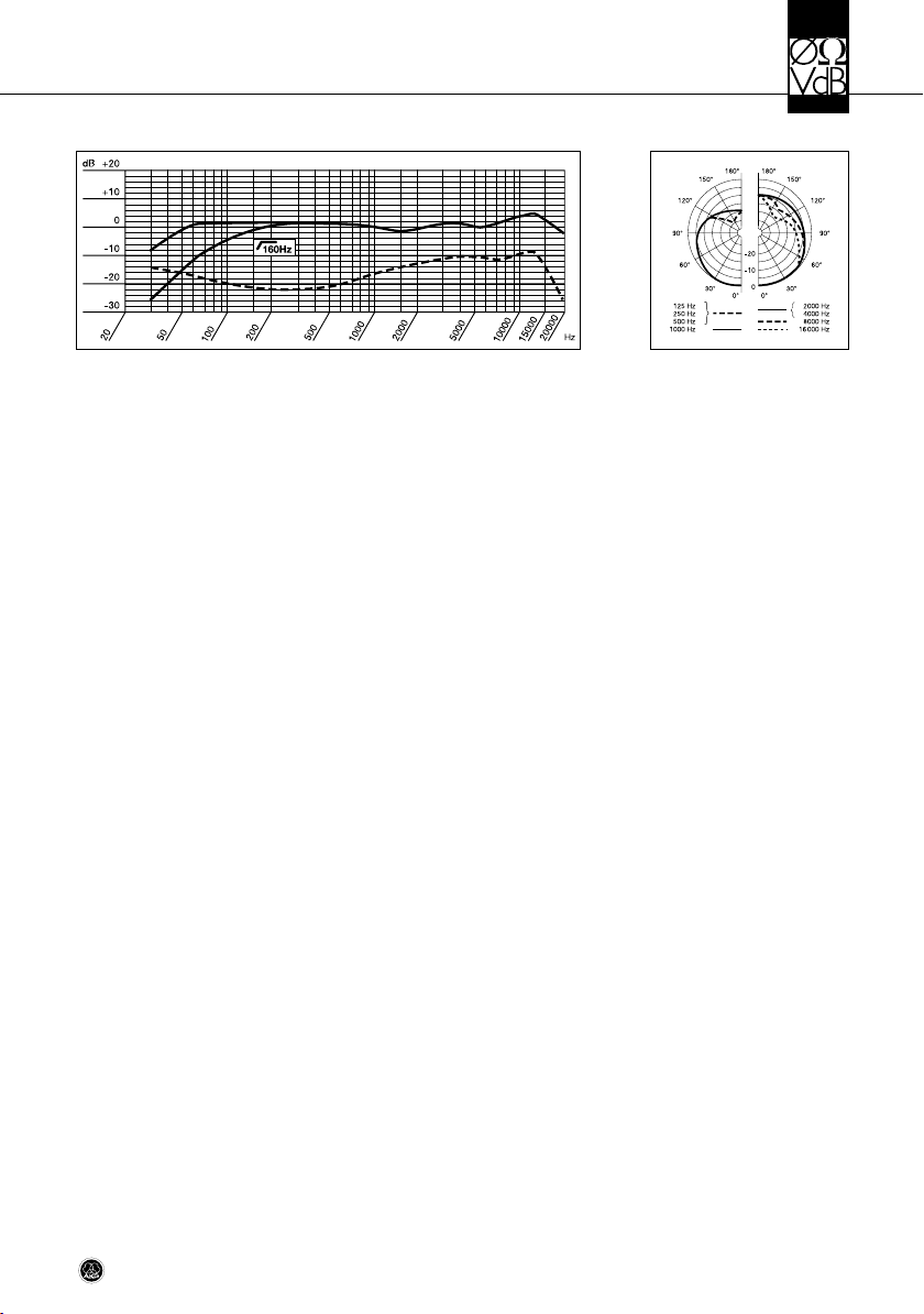
Frequenzgang Polardiagramm
15C 214
Page 16
Table of Contents
Page
Safety ..................................................................................................................17
1 Description..........................................................................................................17
1.0 Introduction ................................................................................................17
1.1 Packing List ................................................................................................17
1.2 Optional Accessories ...................................................................................17
1.3 Brief Description..........................................................................................17
1.4 Controls......................................................................................................18
2 Powering.............................................................................................................19
3 Using the Microphone .........................................................................................20
3.1 Introduction ................................................................................................20
3.2 Bass Cut Filters ...........................................................................................20
3.3 Preattenuation Pads ....................................................................................20
3.4 Stand Mounting...........................................................................................20
3.5 Hints on Microphnone Placement..................................................................20
3.5.1 Lead Vocals........................................................................................21
3.5.2 Choir/Backing Vocals..........................................................................22
3.5.3 Violin, Viola.........................................................................................22
3.5.4 Double Bass, Cello..............................................................................23
3.5.5 Acoustic Guitar ...................................................................................23
3.5.6 Flute..................................................................................................24
3.5.7 Clarinet..............................................................................................24
3.5.8 Tenor/Soprano Saxophone...................................................................24
3.5.9 Trumpet/Trombone .............................................................................25
3.5.10 Grand and Upright Pianos..................................................................25
3.5.11 Electric Guitar/Bass ..........................................................................26
3.5.12 Drums .............................................................................................26
4 Cleaning ..............................................................................................................27
4.1 Microphone ................................................................................................27
4.2 Windscreen ................................................................................................27
5 Specifications .....................................................................................................28
16 C 214
Page 17
Safety
L
• Please make sure that the piece of equipment your microphone will be
connected to fulfills the safety regulations in force in your country and
is fitted with a ground lead.
1 Description
Thank you for purchasing an AKG product. This Manual contains important instructions for setting up and operating your equipment. Please take a few minutes
to read the instructions below carefully before operating the equipment.
Please keep the Manual for future reference. Have fun and impress your audience!
• C 214 microphone
• H 85 shock mount
• W 214 foam windscreen
• High quality carrying case for microphone and standard accessories
• Check that the packaging contains all of the components listed above. Should
anything be missing, please contact your AKG dealer.
• For optional accessories, refer to the current AKG catalog or folder, or visit
www.akg.com. Your dealer will be glad to help.
This large-diaphragm condenser microphone has been designed on the basis of
feedback from sound engineers who have used the C 12, C 12 A, C 414 EB,
C 414 B-ULS, C 414 B-TL II, and C 414 XL II microphones in recording studios
around the world for years. Using hand-selected state-of-the-art, reliable components as well as advanced manufacturing processes, the C 214 meets the highest professional standards and will withstand severe handling in the recording
studio for many years.
The electronic circuitry of the microphone has been redesigned to achieve maximum dynamic range and a flat frequency response. Low self-noise and high headroom add up to a dynamic range of 143 dB (A-weighted).
The transducer element uses advanced backplate technology and a diaphragm
that is gold-sputtered on one side only to prevent local shorting to the back electrode even at extremely high sound pressure levels.
The all-metal body ensures efficient rejection of RF interference so you can use
the microphone near transmitter stations, along with wireless microphones or
other communications equipment.
!
L
1.0 Introduction
1.1 Packing List
1.2 Optional Accessories
1.3 Brief
Description
17C 214
Page 18

1 Description
1.4 Controls
The C 214 provides selector switches for the preattenuation pad and bass cut
filter.
1 Preattenuation Selector
The selector switch on the left-hand side of the microphone (fig. 1) lets you increase the microphone's headroom by 20 dB for distortion-free recordings of very
loud sound sources or close to sound sources. The preattenuation pads prevent
the microphone's output level, particularly at low frequencies, from overloading
the miniature transformers used in mixer input stages, etc.
Fig. 1: Preattenuation selector.
2 Bass Cut Selector
Rumbling or wind noise may cause distortion at very low frequencies. The microphone's switchable bass cut filter (refer to fig. 2) further reduces low-end distortion. The filter slope is more than 6 dB/octave at 160 Hz and below. The bass cut
also minimizes the proximity effect that may arise when close-in miking from less
than 6 inches.
Fig. 2: Bass cut selector.
18 C 214
Page 19
2 Powering
The C 214 provides low self-noise (just 13 dB(A)!) yet high headroom. The microphone requires a phantom power source providing 12 to 52 V as per IEC 61938.
• Do not connect the microphone to any power supply other than a phantom power source (input with phantom power or external IEC standard
phantom power supply) with a floating connector, using a balanced cable
with studio grade connectors to IEC 268-12 only. This is the only way to
ensure safe and reliable operation.
!
L
Important!
19C 214
Page 20
3 Using the Microphone
3.1 Introduction
3.2 Bass Cut Filter
3.3 Preattenuation Pad
3.4 Stand Mounting
3.5 Hints on
Microphone Placement
Table 1: Recommended
applications.
The C 214 features a smooth frequency response similar to the typical sound of
AKG large-diaphragm microphones.
You can use the C 214 for most musical instruments in the studio and on stage
(see also section 3.5). With its cardioid polar pattern, the microphone will give excellent results in a multiplicity of recording situations, particularly, in close miking.
The selectable bass cut filter will effectively cancel out any unwanted noise such
as fan noise from air conditioning systems or low-frequency noise due to floor vibrations, handling noise, etc. without affecting the sound of the recorded voice or
instrument on tape.
The selectable 20-d B preattenuation pad allows you to increase the microphone's
headroom from 136 to 156 dB SPL. Remember to check that the equipment connected to the microphone (microphone preamp, mixer input, recorder input) can
handle the maximum output level of the microphone without causing distortion.
• The supplied H 85 shock mount has a standard 3/8" thread insert so you can
mount the microphone on almost every commercial stand or suspension with
a 3/8" thread.
• To fix the shock mount on a stand with a 5/8" thread, remove the tread insert
and screw the shock mount directly on the stand.
• To remove the shock mount from the microphone, rotate the bayonet-type
lock at the lower end of the shock mount CCW to the point that the shock
mount unlocks.
We recommend the C 214 for the following applications:
Sound source Studio Stage
Lead/solo vocals • •
Backing vocals/choir • • • •
Speech • •
Acoustic guitar • • • •
Electric guitar • • • •
Electric bass • •
Double bass • • • •
Violin • • •
Cello • • •
Zither • • •
Grand piano (classical music)
• • • •
20 C 214
Page 21
3 Using the Microphone
Sound source Studio Stage
Piano (rock & jazz) • • • •
Organ • • •
Trumpet • • • •
Trombone • • •
French horn • • • •
Tuba • • •
Saxophone • • • •
Flute • • • •
Clarinet • • • •
Kick drum • • •
Tom s • •
Cymbals • • • •
Bongos, congas • • • •
• • First choice
• Good alternative
As an introduction to the "secret science of making good recordings", the following sections describe some proven miking techniques.
Table 1 (cont’d)
• Working distance: 6 to 12 in.
(15 to 30 cm)
• Bass cut: ON
• For best results, be sure to
use a pop screen, e.g. the
PF 80 from AKG. If no pop
screen is available, use at
least the supplied W 214
windscreen.
• To give the talent better
control of their own voice,
we recommend adding the
talent's track to their headphone monitor signal.
3.5.1 Lead Vocals
Fig. 3: Solo vocalist.
21C 214
Page 22
3 Using the Microphone
3.5.2 Choir/
Backing Vocals
Refer to section 3.5.1
Lead Vocals above
Fig. 4: Backing vocalists
sharing a single
microphone.
3.5.3 Violin, Viola
To mic up a large choir, we recommend using a pair of microphones plus one spot
microphone each for the soprano, alto, tenor, and bass sections.
In rooms with perfect acoustics, using just a pair of high quality microphones is a
proven way to get superb-sounding recordings.
Backing vocals/technique 1: If enough tracks are available, we recommend
overdubbing each voice separately.
Backing vocals/technique 2:
If only one or two tracks are
available for backing vocals,
use one microphone each for
two or three vocalists maximum. Place the vocalists in a
semicircle in front of the microphone.
Solo violin:
Direct the microphone to the f
holes from a height of 6 to 8 feet
(1.8 to 2.5 m) above the floor.
Large string sections:
Use a combination of a pair of
microphones in an XY, ORTF, or
other stereo configuration and
close-in spot microphones.
Viola:
Direct the microphone to the f
holes from a height of 7 to 10 ft.
(2.2 to 3 m) above the floor.
Fig. 5: Violin.
22 C 214
Page 23
3 Using the Microphone
Double bass:
Align the microphone with one
of the f holes from a distance of
about 16 in. (40 cm). If you
need to record the double bass
together with an ensemble,
place the microphone closer to
the instrument to prevent leakage from other instruments into
the microphone.
Cello/technique 1:
Refer to "Double bass" above.
Cello/technique 2:
Use a close-in microphone as
in technique 1 above plus a distant microphone. Set the level
of the close-in microphone approx. 20 dB lower than the distant mic level.
Refer to fig. 7.
Place the microphone 20 to
40 in. (0.5 to 1 m) away from
the guitar and aim it obliquely
at a point between the sound
hole and neck.
Using two microphones gives
you even better control of the
sound. Point a C 214 at the
sound hole from a distance of
one to two feet (30 to 60 cm).
Place a small-diaphragm microphone (e.g., a C 451B) 20 to
40 in. (0.5 to 1 m) away from
the guitar and align it with a
point between the sound hole
and neck.
3.5.4 Double Bass, Cello
Fig. 6: Double bass.
3.5.5 Acoustic Guitar
Fig. 7: Miking an acoustic
guitar with a single C 214.
23C 214
Page 24
3 Using the Microphone
3.5.6 Flute
Fig. 8: Miking the flute
with a single microphone.
3.5.7 Clarinet
We recommend using two microphones.
Place mic 1 above and to one
side of the player (to reduce
blowing noise) and align it with
the player's mouth, and aim
mic 2 at the instrument from
the side.
If you prefer to use a single microphone, place the microphone as mic 1 above at a
distance of about 7 to 8 1/2 ft.
(2 to 2.5 m) above the floor.
Point the microphone at the
lowest key. To minimize key
noise, place the microphone a
little ways to the side of the instrument.
Fig. 9: Clarinet.
3.7.8 Tenor and Soprano
Saxophones
Fig. 10: Tenor saxophone (a),
soprano saxophone (b).
24 C 214
Aim the microphone at the mid-
a
dle of the instrument from a
distance of about 2 to 3 1/2 ft.
(50 cm to 1 m).
b
Page 25
3 Using the Microphone
Place the microphone about
1 ft. (30 cm) in front of the instrument, slightly off the bell
axis. Switch in one of the preattenuation pads.
Using the supplied windscreen
will help reduce blowing noise.
Grand piano:
Aim a single C 214 or an XY or
ORTF pair of C 214s at the
middle strings from a height
of 5 to 7 ft. (1.5 to 2 m).
For a rock/pop sound, place two
C 214s roughly 8 to 16 in. (20 to
40 cm) above the strings. Align
mic 1 with the treble strings and
mic 2 with the bass strings, both
at a point about 6 in. (15 cm) behind the dampers.
3.5.9 Trumpet,
a
Trombone
b
Fig. 11: Trumpet (a),
trombone (b).
3.5.10 Grand and
Upright Pianos
Upright piano:
Use the same technique as for
the grand. Open the lid and
have the microphones "peek
into the instrument" from
above.
Fig. 12: Grand piano.
Fig. 13: Upright piano.
25C 214
Page 26
3 Using the Microphone
3.5.11 Electric
Guitar/Bass
Fig. 14: Electric guitar.
3.5.12 Drums
Fig. 15: Typical drum kit.
Electric guitar:
Position the microphone 3 to
6 in. (8 to 15 cm) in front of the
speaker, aiming at a point off
the speaker diaphragm center.
Use the bass cut and a preattenuation pad. You may want to
use an additional distant microphone.
Electric bass:
Use the same technique as for
the electric guitar. You can use
a DI box to add the direct signal
of the line output on the bass
amp to the microphone signal.
Overhead miking:
Place two C 214s in an AB or
XY configuration about 2 3/4 to
4 ft. (80 to 120 cm) above the
drummer's head. This technique will pick up the entire kit,
delivering a highly natural sound.
Use little or no EQ!
Hanging and floor toms:
Use one microphone for each
tom or for every two toms,
aligning the microphone with
the rim of the top head. To reduce leakage from other instruments, attenuate the HF range
above 10 kHz using the channel EQ(s).
Kick drum:
• Be sure to switch the preattenuation pad in (-20 dB) because the kick drum
may produce extremely high sound pressure levels.
• Place the microphone right inside the shell.
For a dry, "click" type sound with lots of attack, position the microphone near
the head, at an angle of 45 degrees.
For a fatter sound, place the microphone closer to the front head or outside the
shell, up to 6 in. (15 cm) from the opening in the front head.
26 C 214
Page 27

4 Cleaning
• Use a soft cloth moistened with water to clean the surface of the microphone
body .
• Wash the foam windscreen in soap suds. Do not use the windscreen before it
has dried completely.
4.1 Microphone
4.2 Windscreen
27C 214
Page 28

5 Specifications
Type: 1-inch large-diaphragm backplate pressure
Polar patterns: cardioid
Open-circuit sensitivity: 20 mV/Pa (-34 dBV)
Frequency range: 20 to 20,000 Hz (see frequency
Impedance: ≤ 200 ohms
Recommended load impedance: ≥ 1000 ohms
Bass cut filter slope: 6 dB/octave at 160 Hz
Preattenuation pad: 0/-20 dB (switchable)
Equivalent noise level to
Signal/noise ratio re 1 Pa (A-weighted): 81 dB
Max. SPL for 0.5% THD: 136/156 dB SPL (0/-20 dB)
Dynamic range (A-weighted): 123/143 dB (0/-20 dB)
Environment: temperature: -10°C to +60°C
Powering: 12 to 52 V phantom power
Current consumption: < 2 mA
Connector: IEC standard 3-pin XLR
Dimensions: 54 x 43 x 160 mm / 2.1 x 1.7 x 6.3 in.
Net weight: 290 g / 10.2 oz.
This product conforms to the standards listed in the Declaration of Conformity. To order a free copy of the Declaration of Conformity, visit http://www.akg.com or contact sales@akg.com.
IEC 60268-4 (A-weighted):
gradient microphone
response graphs)
13 dB(A) (0 dB preattenuation)
R.H.: 95% (+20°C); 85% (+60°C)
to IEC 61938
28 C 214
Page 29

5 Specifications
Frequency Response Polar Diagram
29C 214
Page 30

Sommaire
Page
Consigne de sécurité..............................................................................................31
1 Description..........................................................................................................31
1.0 Introduction ................................................................................................31
1.1 Fournitures d’origine ...................................................................................31
1.2 Accessoires optionnels ................................................................................31
1.3 Description succinte ....................................................................................31
1.4 Commandes ...............................................................................................32
2 Alimentation ........................................................................................................33
3 Conseils d’utilisation ...........................................................................................34
3.1 Introduction ................................................................................................34
3.2 Réduction des basses..................................................................................34
3.3 Pré-attenuation...........................................................................................34
3.4 Montage sur un pied....................................................................................34
3.5 Conseils de positionnement..........................................................................34
3.5.1 Soliste vocal.......................................................................................35
3.5.2 Chorale / Choristes .............................................................................36
3.5.3 Violon, alto .........................................................................................36
3.5.4 Contrebasse, violoncelle......................................................................37
3.5.5 Guitare sèche.....................................................................................37
3.5.6 Flûte traversière .................................................................................39
3.5.7 Clarinette...........................................................................................39
3.5.8 Saxophone ténor / soprano..................................................................39
3.5.9 Trompette / Trombone .........................................................................40
3.5.10 Piano à queue / piano droit ................................................................40
3.5.11 Guitare élecgtrique / Guitare basse.....................................................41
3.5.12 Batterie............................................................................................41
4 Nettoyage............................................................................................................42
4.1 Microphone ................................................................................................42
4.2 Bonnette anti-vent.......................................................................................42
5 Caractéristiques techniques................................................................................43
30 C 214
Page 31

Consigne de sécurité
L
• Vérifiez si l’appareil auquel vous voulez raccorder le microphone répond
aux prescriptions relatives à la sécurité en vigueur et s’il possède une
mise à la terre de sécurité.
1 Description
Nous vous remercions d’avoir choisi un produit d’AKG et vous invitons à lire attentivement le présent mode d’emploi avant de mettre votre micro en service. Conservez soigneusement le mode d’emploi pour l’avoir toujours sous la
main lorsque vous avez besoin de le consulter. Nous espérons que vous aurez
beaucoup de satisfaction et de succès avec votre micro.
• Microphone C 214
• Suspension élastique pour le microphone H 85
• Luxueuse mallette de transport pour le microphone et les accessoires fournis
• Vérifiez que l’emballage contient bien toutes les pièces énumérées ci-dessus.
Si une pièce venait à manquer, adressez-vous à votre revendeur AKG.
• Vous trouverez la liste des accessoires optionnels dans le catalogue/dépliant
AKG actuel ou sur www.akg.com. Votre fournisseur se tient à votre disposition
pour vous conseiller.
La construction de ce microphone électrostatique à grand diaphragme repose sur
l’expérience acquise avec les modèles C 12, C 12 A, C 414 EB, C 414 B-ULS,
C 414 B-TL II et C 414 XL II au cours de longues années d’utilisation en studio
dans le monde entier. Basé sur des composants modernes et fiables, sélectionnés
à la main, et sur des processus de production bénéficiant des tout récents progrès
de la technique, ce microphone répond aux plus hautes exigences professionnelles et satisfera très longtemps aux besoins astreignants du studio.
L’électronique du microphone a été repensée en accordant la plus grande importance à l’obtention d’une dynamique et d’une linéarité maximales. Le bruit propre
très faible et la limite de surcharge élevée garantissent une plage dynamique de
143 dB (pondéré A).
Le transducteur a été réalisé en technologie backplate moderne, avec diaphragme
métallisé or sur une face. Cette construction évite les courts-circuits locaux avec la
contre-électrode, même sous les plus fortes pressions sonores.
Le boîtier entièrement métallique protège parfaitement le micro d’éventuels parasites HF lorsque vous utilisez celui-ci à proximité d’un émetteur ou en même
temps que des micros ou autres équipements de communication sans fil.
!
L
1. 0 Introduction
1.1 Fournitures d’origine
1.2 Accessoires
optionnels
1.3 Description
succincte
31C 214
Page 32

1 Description
1.4. Commandes Le C 214 possède un sélecteur de pré-atténuation et un sélecteur de réduction
des basses.
1 Sélecteur de pré-atténuation
Le sélecteur de pré-atténuation au coté gauche du micro (voir Fig. 1) vous permet
de relever la limite de surcharge de 20 dB, pour pouvoir enregistrer sans distorsion
des sources sonores de très haut niveau ou d’enregistrer a proximité des sources
sonores. Cette pré-atténuation évite que le niveau de sortie du micro ne dépasse,
en particulier dans les fréquences basses, les limites de surcharge critiques de
très petits transformateurs utilisés p.ex. sur les entrées des pupitres de mixage.
Fig. 1 : Sélecteur de pré-atténuation
2 Sélecteur de réduction des basses
A très basses fréquences, le rumble et les bruits de vent peuvent provoquer des
distorsions. Le sélecteur de réduction des basses commutable (voir Fig. 2)
concourt à réduire ces distorsions. La pente du filtre est de 6 dB/octave pour une
fréquence de coupure de 160 Hz. La réduction des basses neutralise par ailleurs
l’effet de proximité qui peut se produire lorsque le micro se trouve à faible distance
(moins de 15 cm) de la source sonore.
Fig. 2 : Sélecteur de réduction des basses
32 C 214
Page 33

2 Alimentation
Le C 214 se distingue par son bruit propre faible (13 dB(A) seulement!) s’accompagnant d’un très faible risque de surcharge. Ce micro nécessite une alimentation
fantôme de 12 à 52 V selon IEC 61938.
• Utilisez le microphone exclusivement avec une source d’alimentation
fantôme (entrée disposant d’une alimentation fantôme ou bloc d’alimentation fantôme externe) à la norme CEI sans mise à la terre, et employez à cet effet uniquement un câble symétrique équipé de broches
professionnelles à la norme CEI 268-12. Ce n’est qu’ainsi que vous avez
la garantie d’un fonctionnement sûr et sans problèmes.
!
L
Important !
33C 214
Page 34

3 Conseils d’utilisation
3.1 Introduction
3.2 Réduction
des basses
3.3 Préatténuation
3.4 Montage sur un pied
Outre la grande plage de son niveau de gain et sa construction le mettant à l’abri
des variations de température et d’humidité, ce microphone est caractérisé par
une polyvalence exceptionnelle.
La réponse en fréquence équilibrée s’oriente sur le caractère sonore typique des
microphones AKG à grand diaphragme.
Vous pouvez utiliser le C 214 avec la plupart des instruments de musique, aussi
bien en studio que sur la scène (voir aussi le chapitre 3.5). Grâce à sa caractéristique cardioïde, il peut être utilisé dans les situations de prise de son les plus diverses, en particulier pour la capture de proximité.
La réduction des basses commutable vous permet de faire disparaître efficacement des « sources parasites acoustiques », comme par exemple le souffle des
climatiseurs aussi bien que les vibrations de basses fréquences dues aux oscillations de sol, à des bruits de manipulation etc., sans pour cela modifier les caractéristiques sonores des instruments ou des voix à enregistrer.
La pré-atténuation de 20 dB commutable permet d’augmenter le niveau de pression acoustique maximal du microphone de 136 à 156 dB SPL. Veillez toutefois à
ce que le niveau maximal à la sortie du microphone puisse être transmis sans distorsion aux appareils raccordés (préamplificateurs de microphone, entrées de
console de mixage, entrées des appareils d'enregistrement).
• La suspension élastique H 85, fournie avec le microphone, dispose d’un filetage standard de 3/8". Celui-ci vous permet de monter le microphone sur la
plupart des pieds et suspensions disponibles dans le commerce.
• Pour monter le microphone sur un filetage de 5/8", il suffit d’enlever le filetage
d’origine et de monter directement la suspension élastique sur le pied.
• Pour désaccoupler la suspension élastique du microphone, tournez la baïonnette située au bas du microphone dans le sens contraire aux aiguilles d’une
montre pour ouvrir le loquet.
3.5 Conseils
de positionnement
Tableau 1 : Applications
recommandées
34 C 214
Nous recommandons le C 214 pour les applications suivantes :
Source sonore Studio Sonorisation
Soliste vocal • •
Choristes/chorale • • • •
Parole • •
Guitare sèche • • • •
Guitare électrique • • • •
Guitare basse • •
Contrebasse • • • •
Violon • • •
Violoncelle • • •
Cithare • • •
Piano à queue (m. classique)
• • • •
Page 35

3 Conseils d’utilisation
Source sonore Studio Sonorisation
Piano droit (rock & jazz) • • • •
Orgue • • •
Trompette • • • •
Trombone • • •
Cor • • • •
Tuba • • •
Saxophone • • • •
Flûte traversière • • • •
Clarinette • • • •
Grosse caisse • • •
Tom s • •
Cymbales • • • •
Bongos, congas • • • •
• • particulièrement recommandé
• recommandé
En guise d’introduction aux techniques de l’enregistrement, vous trouverez cidessous l’essentiel des règles de positionnement de microphones.
Tableau 1 (cont.)
• Distance du microphone : 15
- 30 cm
• Pour obtenir un résultat optimal nous conseillons
d’utiliser un écran antipops, p.ex. le PF 80 d’AKG.
Si vous n’avez pas d’écran
anti-pops à portée de la
main vous pouvez prendre
la bonnette anti-vent W 214
fournie.
• Nous recommandons, pour
un meilleur con-trôle de la
voix, de lui consacrer une
piste à part au retour de
casque du/de la soliste.
3.5.1 Soliste vocal
Fig. 3 : Chanteuse
35C 214
Page 36

3 Conseils d’utilisation
3.5.2 Chorale / choristes
Voir le chapitre 3.5.1
Voix soliste.
Fig. 4 : Choristes avec un
microphone
3.5.3 Violon, alto
Pour les grands chœurs nous conseillons d’utiliser une paire de micros ainsi
qu’un microphone de soutien chaque pour les registres soprano, alto, ténor et
basse.
Dans une salle présentant des conditions acoustiques optimales vous pouvez déjà
obtenir d’excellents résultats avec deux micros de haute qualité.
Chœur d’accompagnement/Variante 1 : Si vous disposez d’un nombre suffisant de voies nous vous conseillons d’enregistrer successivement chaque voix séparément.
Chœur d’accompagnement/Variante 2 :
Si vous ne disposez que d’une
ou deux voies, utilisez un micro
pour deux ou trois personnes
au maximum. Placez le chœur
en demi-cercle devant le microphone.
Violon solo :
Dirigez le microphone vers les
ouïes, à une hauteur de 1,8 m à
2,5 m.
Grands ensembles à cordes :
Utilisez une paire de microphones en configuration stéréo
XY, ORTF ou autre, combiné à
des microphones d’appoint à
proximité des instruments.
Alto :
Dirigez le microphone vers
les ouïes, à une hauteur de 2,2
à 3 m.
Fig. 5 : Violon
36 C 214
Page 37

3 Conseils d’utilisation
Contrebasse :
Placez le microphone à environ
40 cm de l’une des ouïes. Si la
contrebasse doit être enregistrée au sein d’un ensemble instrumental, réduisez la distance,
pour éviter que d’autres in struments n’interfèrent sur le microphone de la contrebasse.
Violoncelle/variante 1 :
Voir la contrebasse.
Violoncelle/variante 2 :
Un microphone de proximité
comme dans la variante 1, auquel on adjoint un microphone
d’ambiance. Le niveau du microphone de proximité est plus bas d’environ 20 dB que celui du microphone
d’ambiance.
Voir Fig. 7.
Orientez le C 214 obliquement
sur l’espace entre l’ouïe et le
manche, en le plaçant à une
distance de 50 cm à 1 m.
Si vous souhaitez une très
grande exactitude du son nous
recommandons d’utiliser deux
micros : placez un C 214 à une
distance de 30 à 60 cm en
l’orientant sur l’ouïe et un microphone à petit diaphragme
(p.ex. C 451B) à une distance de
50 cm à 1 m en l’orientant sur
l’espace entre ouïe et manche.
3.5.4 Contrebasse,
violoncelle
Fig. 6 : Contrebasse
3.5.5 Guitare sèche
Fig. 7 : Guitare sèche
avec un C 214
37C 214
Page 38

3 Conseils d’utilisation
3.5.6 Flûte traversière
Fig. 8 : Prise de son d’une
flûte traversière au moyen
d’un microphone unique
3.5.7 Clarinette
Nous recommandons l’utilisation de deux microphones.
Placez le microphone 1 audessus de la bouche de l’instrumentiste (pour éviter les
bruits de souffle) et dirigé vers
celle-ci, et dirigez le microphone 2 latéralement vers
l’instrument.
Prise de son au moyen d’un microphone unique :
comme avec le microphone 1,
à environ 2 m et à une hauteur
de 2 m à 2,5 m au-dessus du
sol.
Dirigez le microphone vers la
clef la plus basse. Pour réduire
les bruits de clefs, placez le microphone légèrement en biais
par rapport à l’instrument.
Fig. 9 : Clarinette
3.5.8 Saxophone
ténor / soprano
Fig. 10 : Saxophone ténor (a),
saxophone soprano (b)
38 C 214
Dirigez le microphone vers le
a
milieu de l’instrument, à une
distance de 50 cm à 1 m.
b
Page 39

3 Conseils d’utilisation
Placez le microphone devant
l’instrument, à environ 30 cm
et hors de l’axe du pavillon. Sélectionnez la pré-atténuation
sur le microphone. La bonnette
anti-vent fournie permet de réduire les bruits de souffle.
Piano à queue :
Dirigez un C 214 ou deux
C 214 en configuration XY ou
ORTF vers les cordes du registre médium, à une hauteur
d’environ 1,5 à 2 m.
Pour obtenir un son pop ou
rock, utilisez deux C 214 placés
à environ 20 à 40 cm au-dessus des cordes. Dirigez le microphone 1 vers le registre médium et le microphone 2 vers
les basses, à environ 15 cm
derrière les étouffoirs.
3.5.9 Trompette /
a
trombone
b
Fig. 11 : Trompette (a),
trombone (b)
3.5.10 Piano à queue /
piano droit
Fig. 12 : Piano à queue
Piano droit :
Procédez comme pour le piano
à queue. Ouvrez le couvercle et
dirigez les microphones vers
l’intérieur de l’instrument.
Fig. 13 : Piano droit
39C 214
Page 40

3 Conseils d’utilisation
3.5.11 Guitare életrique /
Guitare basse
Fig. 14 : Guitare électrique
3.5.12 Batterie
Fig. 15 : Batterie
Guitare électrique :
Placez le microphone à une
distance de 8 à 15 cm de la
membrane du haut-parleur, légèrement décalé par rapport
au centre de celle-ci. Sélectionnez la réduction des basses
et la pré-atténuation. Prévoy ez
éventuellement un deuxième
microphone d’ambiance.
Guitare basse :
Procédez comme pour la guitare électrique. Vous pouvez
ajouter au mixage le signal direct, en passant par une boîte
de direct (DI-Box) en utilisant la sortie en ligne de l’amplificateur de la basse.
Prise de son « overhead » :
Placez deux C 214 en configuration AB ou XY à une distance
de 80 à 120 cm au-dessus de
la tête du batteur. Cette technique permet une prise de son
très naturelle de l’ensemble de
la batterie (peu ou pas d'utilisation de l’égaliseur recommandée).
Toms-toms et floor-toms :
Dirigez à une distance de 5 à
10 cm un microphone vers
chaque tom ou dirigez un microphone entre deux toms, vers
le bord de la peau. Pour mini-
miser les interférences provenant d’autres instruments, baissez les aigus au-dessus de 10 kHz sur la console
de mixage.
Grosse caisse :
• Il est indispensable d’activer la pré-atténuation (-20 dB), le niveau sonore
fourni par la grosse caisse pouvant être extrêmement élevé.
• Placez le micro directement dans la caisse.
Pour obtenir un son très sec (« click ») avec une forte attaque, placez le micro
près de la peau de frappe sous un angle de 45°.
Pour obtenir un son ayant plus de rondeur, placez le micro plus près de la peau
de résonance ou jusqu’à 15 cm à l’extérieur de l’ouverture de cette dernière.
40 C 214
Page 41

4 Nettoyage
• Pour nettoyer le micro, utilisez un chiffon légèrement humide, jamais un chiffon mouillé.
• Lavez la bonnette anti-vent en mousse à l'eau savonneuse. Une fois sèche, la
bonnette anti-vent peut être immédiatement réutilisée.
4.1 Microphone
4.2 Bonnette anti-vent
41C 214
Page 42

5 Caractéristiques techniques
Principe :
Directivité : cardioïde
Sensibilité (tension de circuit ouvert) : 20 mV/Pa (-24 dBV ± 0,5 dB)
Réponse en fréquence : 20 à 20.000 Hz
Impédance électrique : ≤ 200 ohms
Impédance de charge recommandée : ≥ 100 ohms
Pente du filtre de réduction des basses : 6 dB/octave à 160 Hz
Pré-atténuation : 0 / -20 dB, commutable
Niveau de bruit équivalent
selon CEI 60268-4 (valeur pondérée A) : 13 dB(A) (pré-atténuation à 0 dB)
Rapport signal/bruit pour 1 Pa (valeur pondérée A) : 81 dB
Niveau de pression acoustique maxi.
pour 0,5% de distorsion par harmonique : 136 / 156 dB SPL (0 / -20 dB)
Dynamique (valeur pondérée A) : 123 / 143 dB (0 / -20 dB)
Conditions climatiques tolérées : Température : -10°C à +60°C
Tension d’alimentation : Alimentation fantôme, 12 - 52 V,
Consommation : < 2 mA
Connecteur : Type XLR-3 selon norme CEI
Dimensions extérieures : 54 x 43 x 160 mm
Poids net : 290 g
système backplate à large membrane de 25 mm
selon le principe des gradients de pression
(voir courbe de réponse)
Humidité relative : 95% (+20°C),
85% (+60°C)
selon norme CEI 61938
Ce produit est conforme aux normes citées dans la Déclaration de Conformité, dont vous pouvez prendre connaissance en consultant le site http://www.akg.com ou en adressant un e-mail à sales@akg.com.
42 C 214
Page 43

5 Caractéristiques techniques
Réponse en fréquence Diagramme polaire
43C 214
Page 44

Indice
Pagina
Indicazione per la sicurezza ...................................................................................45
1 Descrizione .........................................................................................................45
1.0 Introduzione................................................................................................45
1.1 In dotazione ................................................................................................45
1.2 Accessori opzionali......................................................................................45
1.3 Breve descrizione ........................................................................................45
1.4 Elementi di comando ...................................................................................46
2 Alimentazione......................................................................................................47
3 Istruzioni per l’impiego........................................................................................48
3.1 Introduzione................................................................................................48
3.2 Attenuazione dei bassi .................................................................................48
3.3 Preattenuazione..........................................................................................48
3.4 Montaggio su supporto ................................................................................48
3.5 Consigli per il posizionamento......................................................................48
3.5.1 Voce solista ........................................................................................49
3.5.2 Coro/coro d’accompagnamento...........................................................50
3.5.3 Violino, viola .......................................................................................50
3.5.4 Contrabbasso, violoncello....................................................................51
3.5.5 Chitarra acustica ................................................................................51
3.5.6 Flauto traverso ...................................................................................52
3.5.7 Clarinetto...........................................................................................52
3.5.8 Sassofono tenore/soprano...................................................................52
3.5.9 Tromba/trombone...............................................................................53
3.5.10 Pianoforte a coda/pianoforte verticale.................................................53
3.5.11 Chitarra elettrica/basso elettrico ........................................................54
3.5.12 Batteria............................................................................................54
4 Pulizia .................................................................................................................55
4.1 Microfono...................................................................................................55
4.2 Antisoffio....................................................................................................55
5 Dati tecnici ..........................................................................................................56
44 C 214
Page 45
Inidcazione per la sicurezza
L
• Controllate per favore se l’apparecchio che volete collegare al microfono corrisponde alle norme di sicurezza vigenti e se è dotato di una
messa a terra di sicurezza.
1 Descrizione
Vi ringraziamo di aver scelto un prodotto dell‘AKG. Leggete per favore attentamente le istruzioni per l’uso prima di usare l’apparecchio e conservate le
istruzioni per l’uso per poterle consultare in caso di necessità. Vi auguriamo buon
divertimento e molto successo!
• Microfono C 214
• Sospensione elastica del microfono H 85
• Antisoffio in espanso W 214
• Pregiata valigetta di trasporto per il microfono e gli accessori in dotazione
• Controllate, per favore, se la confezione contiene tutti i componenti sopra elencati. Se dovesse mancare qualche cosa, rivolgetevi al vostro rivenditore AKG.
• Accessori opzionali si trovano nel catalogo/folder attuale dell'AKG o al sito
www.akg.com. Il vostro rivenditore è a vostra disposizione per eventuali consigli.
La costruzione di questo microfono a condensatore a grande membrana si basa
sulle esperienze fatte su scala mondiale, nell'esercizio pluriennale in studio, con i
modelli C 12, C 12 A, C 414 EB, C 414 B-ULS, C 414 B-TL II e C 414 XL II. Basato
su componenti moderne e affidabili, selezionate a mano e processi avanzati di
produzione, il microfono corrisponde alle più alte esigenze professionali e resisterà
anche al lungo ed esigente impiego in studio.
L'elettronica del microfono è stata rielaborata; si è posta grandissima attenzione
alla massima dinamica e linearità. Il rumore proprio ridotto e la vasta gamma di
modulazione garantiscono una dinamica di circa 143 dB (ponderazione A).
Il trasduttore è composto di tecnologia moderna backplate ed è provvisto di una
membrana vaporizzata in oro su un lato. Questa costruzione evita cortocircuiti locali con il controelettrodo anche con altissime pressioni sonore.
La scatola interamente metallica agisce bene contro eventuali dispersioni RF
quando usate il microfono nelle vicinanze di un trasmettitore o insieme a microfoni
senza filo o altri apparecchi di comunicazione.
!
L
1.0 Introduzione
1.1 In dotazione
1.2 Accessori opzionali
1.3 Breve descrizione
45C 214
Page 46

1 Descrizione
1.4 Elementi
di comando
Il C 214 è dotato di un selettore per selezionare la preattenuazione ed uno per l'attenuazione dei bassi.
1 Selettore per la preattenuazione
Il selettore disposto sul lato sinistro del microfono (vedi fig. 1) Vi permette di aumentare il limite di modulazione di 20 dB, per poter effettuare registrazioni libere
da distorsioni anche di fonti sonore di volume molto alto, nonché nelle vicinanze
della fonte sonora. Questa preattenuazione impedisce che il livello d'uscita del microfono, particolarmente nel caso di frequenze basse, superi i limiti critici di modulazione dei mini-trasformatori usati per es. per ingressi di mixer.
Fig. 1: Selettore per la preattenuazione
2 Selettore per l'attenuazione dei bassi
Rumori o vento ecc. possono causare distorsioni nelle frequenze più basse. L'attenuazione dei bassi regolabile (vedi fig. 2) riduce addizionalmente queste distorsioni. La transconduttanza del filtro supera i 6 dB/ottava al di sotto di una frequenza limite di 160 Hz. L'attenuazione dei bassi riduce anche l'effetto di prossimità, che può causarsi quando il microfono dista poco (meno di 15 cm) dalla fonte
sonora.
Fig. 2: Selettore per l'attenuazione dei bassi
46 C 214
Page 47

2 Alimentazione
Il C 214 si contraddistingue per il rumore proprio basso (solo 13 dB(A)!) e la contestuale elevata resistenza ai sovraccarichi. Questo microfono necessita di un'alimentazione phantom da 12 fino a 52 V secondo IEC 61938.
• Collegate il microfono esclusivamente a fonti d’alimentazione phantom
(ingresso con alimentazione phantom oppure alimentatore phantom
esterno) secondo IEC con collegamento senza terra e utilizzate solo un
cavo simmetrico con connettori da studio secondo IEC 268-12. Solo in
questo modo è garantito l’esercizio sicuro e senza problemi.
!
L
Importante!
47C 214
Page 48

3 Istruzioni per l’impiego
3.1 Introduzione
3.2 Attenuazione
dei bassi
3.3 Preattenuazione
3.4 Montaggio
su supporto
Oltre alla larga gamma di modulazione con minime distorsioni e alla costruzione
resistente a temperature estreme e all’umidità, il microfono offre possibilità uniche
d’impiego universale.
La risposta in frequenza equilibrata si orienta al carattere sonoro tipico per microfoni a grande membrana AKG.
Il C 214 può essere impiegato sia nello studio che sul palco per la maggior parte
degli strumenti musicali (vedi anche il capitolo 3.5). Con la sua direttività cardioide
è adatto a diverse situazioni di ripresa, particolarmente per la ripresa nelle dirette
vicinanze.
L’attenuazione dei bassi commutabile Vi permette di filtrare in modo efficace fonti
di disturbo acustiche, come p.e. correnti d’aria prodotte da impianti di climatizzazione o vibrazioni a basse frequenze causate da oscillazioni del suolo, rumori prodotti dal tocco delle mani ecc., senza alterare il carattere sonoro della voce/dello
strumento da riprendere.
Con la preattenuazione di 20 dB commutabile potete aumentare la gamma di modulazione acustica del microfono da 136 a 156 dB SPL. Fate attenzione affinché il
livello massimo all’uscita microfonica possa venir elaborato, senza distorsioni, dagli apparecchi collegati a valle (preamplificatore microfonico, ingressi di mixer, ingressi di apparecchi di registrazione).
• La sospensione elastica in dotazione H 85 è provvista di un adattatore di filetto
da 3/8" con cui potete montare il microfono su quasi tutti i supporti in uso
commerciale e su sospensioni con filetti da 3/8".
• Per montare il microfono su supporti con filetti da 5/8", togliete l’adattatore di
filetto e avvitate la sospensione elastica direttamente sul supporto.
• Per sfilare la sospensione elastica dal microfono, girate il dispositivo di sicurezza del tipo baionetta disposto sull’estremità inferiore della sospensione in
senso antiorario per aprire il dispositivo.
per il posizionamento
3.5 Consigli
Tabella 1: Impieghi
raccomandati
48 C 214
Raccomandiamo il C 214 per i seguenti impieghi:
Fonte sonora Nello studio Sul palco
Voce solista • •
Backing vocals/coro • • • •
Voce parlata • •
Chitarra acustica • • • •
Chitarra elettrica • • • •
Basso elettrico • •
Contrabbasso • • • •
Violino • • •
Violoncello • • •
Cetra • • •
Pianof. a coda (m. classica)
• • • •
Page 49

3 Istruzioni per l’impiego
Fonte sonora Nello studio Sul palco
Pianof. vert. (rock & jazz) • • • •
Organo • • •
Tromba • • • •
Trombone • • •
Corno • • • •
Tuba • • •
Sassofono • • • •
Flauto traverso • • • •
Clarinetto • • • •
Bass drum • • •
Tom s • •
Piatti • • • •
Bongos, congas • • • •
• • Adattissimo
• Adatto
Per rendervi familiari con la "scienza della tecnica di registrazione" vi diamo qui di
seguito alcuni consigli per posizionamenti di microfoni che si sono dimostrati validi.
Tabella 1 (cont.)
• Distanza dal microfono: 15
- 30 cm
• Attenuazione dei bassi: inserita
• Per ottenere risultati ottimi
consigliamo di posizionare
un antipopping, ad es. un
PF 80 dell'AKG. Se non esiste l'antipopping, potete
usare anche l'antisoffio
W 214 in dotazione.
• Raccomandiamo di far
ascoltare attraverso la cuffia al cantante/relatore, durante la ripresa, la propria
traccia, per permettergli di
controllare meglio la sua
voce.
3.5.1 Voce solista
Fig. 3: Cantante solista
49C 214
Page 50

3 Istruzioni per l’impiego
3.5.2 Coro/coro d’accompagnamento
Vedi capitolo 3.5.1
voce solista.
Fig. 4: Coro d’accompa-
gnamento con un
microfono solo
3.5.3 Violino, viola
Per grandi cori raccomandiamo un paio di microfoni nonché rispettivamente un
microfono di supporto per soprano, contralto, tenore e basso.
In sale acusticamente ottimali potete raggiungere risultati eccellenti soprattutto
con soli due microfoni d'alta qualità.
Coro d'accompagnamento/variante 1: Se c'è a disposizione un numero sufficiente di tracce, raccomandiamo di registrare separatamente ogni voce, una dopo
l'altra.
Coro d'accompagnamento/
variante 2:
Se avete solo una o due tracce
a disposizione, usate un microfono per due o per un massimo
di tre persone. Posizionate il
coro in un semicerchio davanti
al microfono.
Violino solista:
Posizionate il microfono da
un’altezza di 1,8 a 2,5 m in
modo che sia orientato sulle
effe.
Grandi gruppi di archi:
Usate un paio di microfoni in
posizione XY, ORTF o in un’altra
posizione stereo, combinato
con microfoni di supporto nelle
vicinanze.
Viola:
Posizionate il microfono da
un’altezza di 2,2 a 3 m in modo
che sia orientato sulle effe.
Fig. 5: Violino
50 C 214
Page 51

3 Istruzioni per l’impiego
Contrabbasso:
Posizionate il microfono da una
distanza di circa 40 cm in
modo che sia orientato su una
delle effe. Se il contrabbasso
deve venir ripreso contemporaneamente ad un complesso, riducete la distanza per evitare il
leakage di altri strumenti nel
microfono.
Violoncello/variante 1:
Vedi contrabbasso.
Violoncello/variante 2:
Un microfono a distanza ravvicinata come nella variante 1 ed
in più un microfono spaziale.
Regolate il livello del microfono ravvicinato circa 20 dB al di sotto di quello spaziale.
Vedi fig. 7.
Posizionate il C 214 in una distanza da 50 cm fino ad 1 m in
modo obliquo tra foro di risonanza e collo.
Per la configurazione particolarmente esatta del suono consigliamo di usare due microfoni: posizionate un C 214 ad
una distanza tra 30 e 60 cm sul
foro di risonanza. Orientate un
microfono a membrana piccola
(ad es. C 451B) ad una distanza
di ca. 50 cm fino ad 1 m verso
l'area tra foro di risonanza e
collo.
3.5.4 Contrabbasso,
violoncello
Fig. 6: Contrabbasso
3.5.5 Chitarra acustica
Fig. 7: Chitarra acustica
con un C 214 solo
51C 214
Page 52

3 Istruzioni per l’impiego
3.5.6 Flauto traverso
Fig. 8: Ripresa del flauto
traverso con un
microfono solo
3.5.7 Clarinetto
Raccomandiamo l’uso di due
microfoni.
Orientate il microfono 1 obliquamente da sopra sulla bocca
dello strumentalista (meno rumori da soffio), il microfono 2
lateralmente sullo strumento.
Ripresa con un microfono solo:
come il microfono 1, ad una distanza di circa 2 m, a 2 - 2,5 m
sopra il pavimento.
Orientate il microfono sull’ultima chiavetta inferiore. Per minimizzare i rumori prodotti dalle
chiavette, posizionate il microfono un po’ lateralmente dallo
strumento.
Fig. 9: Clarinetto
3.5.8 Sassofono
tenore/soprano
Fig. 10: Sassofono
tenore (a), sassofono
soprano (b)
52 C 214
Orientate il microfono da una
a
distanza di circa 50 cm – 1 m
sul centro dello strumento.
b
Page 53

3 Istruzioni per l’impiego
Posizionate il microfono ad una
distanza di circa 30 cm davanti
allo strumento, un po’ fuori dell’asse del padiglione. Inserite sul
microfono la preattenuazione.
L’antisoffio in dotazione aiuta a
ridurre i rumori prodotti dal soffio.
Pianoforte a coda:
Orientate un C 214 oppure due
C 214 in posizione XY o ORTF
da un’altezza di 1,5 - 2 m sulle
corde centrali.
Per i sound rock/pop usate due
C 214, circa 20-40 cm sopra le
corde. Orientate il microfono 1
sulla zona delle corde centroacute, il microfono 2 sulla zona
dei bassi, sempre circa 15 cm
dietro gli smorzatori.
3.5.9 Tromba/trombone
a
b
Fig. 11: Tromba (a),
trombone (b)
3.5.10 Pianoforte
a coda/pianoforte
verticale
Pianoforte verticale:
Ripresa come per il pianoforte
a coda. Aprite lo strumento e
fate "guardare" i microfoni dall’alto nello strumento.
Fig. 12: Pianoforte
a coda
Fig. 13: Pianoforte
verticale
53C 214
Page 54

3 Istruzioni per l’impiego
3.5.11 Chitarra
elettrica/basso elettrico
Fig. 14: Chitarra elettrica
3.5.12 Batteria
Fig. 15: Batteria
Chitarra elettrica:
Posizionate il microfono ad una
distanza di 8-15 cm leggermente fuori del centro della
membrana degli altoparlanti.
Atti vate l’attenuazione dei
bassi e la preattenuazione.
Usate eventualmente un secondo microfono spaziale.
Basso elettrico:
Come la chitarra elettrica. In più
potete mixare il segnale diretto
con il segnale microfonico, con
un box DI collegato all’uscita
Line dell’amplificatore del basso.
Ripresa overhead:
Posizionate due C 214 in tecnica AB o XY ad una distanza di
80 cm - 120 cm sopra la testa
del batterista. Questa tecnica
fornisce un’immagine sonora
molto naturale di tutta la batteria (usare poca o nessuna
equalizzazione/regolazione del
suono).
Toms sospesi e floor toms:
Da una distanza di 5 a 10 cm
orientate un mi crofono per tom
o ri spettivamente un microfono
tra due toms sull’orlo della
pelle. Per ridurre il leakage di
altri strumenti, riducete sul mixer gli acuti superiori ai 10 kHz.
Bassdrum:
• Attivate in ogni caso la preattenuazione (-20 dB), poiché il bassdrum può produrre livelli sonori estremamente alti.
• Posizionate il microfono direttamente nella cassa.
Per un suono molto aspro (“clicc”) con molto attacco, posizionate il microfono
in un angolo di 45° vicino alla pelle battente.
Per un suono con più profondità posizionate il microfono più vicino alla membrana di risonanza o fino a 15 cm fuori dal foro della membrana di risonanza.
54 C 214
Page 55

4 Pulizia
• Pulite la superficie della scatola del microfono con un panno inumidito con acqua.
• Lavate l’antisoffio in espanso con acqua e sapone. Dopo l’asciugamento l’antisoffio può venir usato subito.
4.1 Microfono
4.2 Antisoffio
55C 214
Page 56

5 Dati tecnici
Modo di funzionamento: Sistema backplate a grande membrana da 25 mm
Direttività: cardioide
Sensibilità: 20 mV/Pa (-34 dBV)
Risposta in frequenza: da 20 a 20.000 Hz
Impedenza elettrica: ≤ 200 Ohm
Impedenza di carico raccomandata: ≥ 1000 Ohm
Transconduttanza del filtro di attenuazione dei bassi:
Preattenuazione: 0/-20 dB (regolabile)
Livello di pressione equivalente
secondo IEC 60268-4 (pond. A.): 13 dB(A) (0 dB preattenuazione)
Rapporto segnale/rumore rif. a 1 Pa (pond. A.): 81 dB
Pressione acustica limite per un coefficiente
di distorsione armonica dello 0,5%: 136/156 dB SPL (0/-20 dB)
Gamma dinamica (pond. A.): 123/143 dB (0/-20 dB)
Condizioni climatiche ammissibili: temperature: da -10°C fino a +60°C
Tensione di alimentazione: 12 - 52 Volt alimentazione phantom
Assorbimento: < 2 mA
Cablaggio connettori: tipo XLR-3 secondo IEC
Dimensioni esterne: 54 x 43 x 160 mm
Peso: 290 g netti
secondo il principio del gradiente di pressione
(vedi curva di risposta in frequenza)
6 dB/ottava con punto d’inserzione a 160 Hz
umidità d’aria relativa: 95% (+20°C), 85%
(+60°C)
secondo IEC 61938
Questo prodotto corrisponde alle norme elencate nella dichiarazione di conformità, che è disponibile al sito
http://www.akg.com oppure all'indirizzo email sales@akg.com.
56 C 214
Page 57

5 Dati tecnici
Risposta in frequenza Diagramma polare
57C 214
Page 58

Índice
Página
Indicaciones de seguridad .....................................................................................59
1 Descripción .........................................................................................................59
1.0 Introducción................................................................................................59
1.1 Volumen de suministros...............................................................................59
1.2 Accesorios opcionales .................................................................................59
1.3 Breve descripción ........................................................................................59
1.4 Controles....................................................................................................60
2 Alimentación .......................................................................................................61
3 Indicaciones de aplicación ..................................................................................62
3.1 Introducción................................................................................................62
3.2 Atenuación de bajos ....................................................................................62
3.3 Preatenuación.............................................................................................62
3.4 Montaje en el soporte ..................................................................................62
3.5 Consejos para el emplazamiento...................................................................62
3.5.1 Vocalista solista ..................................................................................63
3.5.2 Coro/coro de acompañamiento............................................................64
3.5.3 Violín, viola .........................................................................................64
3.5.4 Contrabajo, violoncelo.........................................................................65
3.5.5 Guitarra acústica ................................................................................65
3.5.6 Flauta travesera..................................................................................66
3.5.7 Clarinete............................................................................................66
3.5.8 Saxofón tenor/soprano........................................................................66
3.5.9 Trompeta/trombón..............................................................................67
3.5.10 Piano de cola/vertical........................................................................67
3.5.11 Guitarra eléctrica/bajo eléctrico .........................................................68
3.5.12 Batería.............................................................................................68
4 Limpieza..............................................................................................................69
4.1 Micrófono...................................................................................................69
4.2 Pantalla antiviento........................................................................................69
5 Datos técnicos.....................................................................................................70
58 C 214
Page 59

Indicaciones de seguridad
L
• Sírvase verificar si el aparato al cual quiere conectar el micrófono cumple con las disposiciones de seguridad vigentes y está equipado con
una toma de tierra de seguridad.
1 Descripción
Muchas gracias por haberse decidido por un producto de la empresa AKG. Tómese, por favor, unos momentos para leer el Modo de Empleo antes de usar el
aparato. Guarde las instrucciones de empleo en un lugar seguro de modo que
pueda consultarlas si se le presenta alguna duda. ¡Que se divierta y que tenga mucho éxito con su nuevo equipo!
• Micrófono C 214
• Suspensión de micrófono elástica H 85
• Pantalla antiviento de goma espuma W 214
• Maletín de transporte de excelente calidad para el micrófono y los acceso-
rios suministrados.
• Sírvase controlar que el embalaje contenga todas las piezas arriba mencionadas. Si falta algo, rogamos dirigirse a su distribuidor AKG.
• Los accesorios opcionales los encontrará en el más reciente Catálogo/Folleto
de AKG o en www.akg.com. Su distribuidor lo asesorará con mucho gusto.
La construcción de este micrófono de condensador de gran membrana se basa en
las experiencias obtenidas durante largos años en los estudios en todo el mundo
con los modelos C 12, C 12 A, C 414 EB, C 414 B-ULS, C 414 B-TL II y C 414 XL II.
Recurriendo a componentes electrónicas seguras, modernas y seleccionadas manualmente y a procesos de producción avanzados, el micrófono está a la altura de
las más elevadas exigencias profesionales y es capaz de resistir el uso prolongado
y riguroso en un estudio.
La electrónica del micrófono fue reelaborada, haciendo hincapié en una dinámica
y linealidad máximas. El reducido ruido inherente y la amplia gama de modulación
garantizan un margen de volumen de 143 dB (ponderado en A).
La cápsula transductora está construida con la moderna tecnología de contraplaca y dispone de una membrana metalizada con oro por un lado. Este método de
construcción impide que – incluso con las más altas presiones sonoras – se produzcan cortocircuitos con el contraelectrodo.
La caja enteramente de metal sirve muy bien contra posibles interferencias de RF
cuando se usa el micrófono en las cercanías del transmisor o junto con micrófonos inalámbricos u otros equipos de comunicación.
!
L
1.0 Introducción
1.1 Volumen de
suministros
1.2 Accesorios
opcionales
1.3 Breve descripción
59C 214
Page 60

1 Descripción
1.4 Controles
El C 214 dispone de conmutadores-selectores para la preatenuación y la atenuación de bajos.
1 Conmutador-selector para preatenuación
El conmutador-selector en la parte izquierda del micrófono (véase Fig. 1) le permite subir en 20 dB el límite de modulación para poder hacer grabaciones sin distorsiones tanto de fuentes sonoras con mucho volumen como también en las proximidades de fuentes sonoras. Esta preatenuación impide que – sobre todo con
frecuencias bajas - el nivel de salida del micrófono sobrepase los niveles críticos
de modulación de microtransformadores que son utilizados, por ejemplo, en las
entradas de los pupitres de mezcla.
Fig. 1: Conmutador-selector para preatenuación
2 Conmutador-selector para atenuación de bajos
Los ronguidos, ruidos de viento u otros ruidos pueden producir distorsiones con
las frecuencias más bajas. La atenuación de bajos conmutable (véase Fig. 2) reduce aun más estas distorsiones. La transductancia del filtro asciende a 6 dB/octava con una frecuencia de corte de 160 Hz. La atenuación de bajos contrarresta
también el efecto de proximidad que puede producirse con reducidas distancias
(de menos de 15 cm) entre el micrófono y la fuente sonora.
Fig. 2: Conmutador-selector para atenuación de bajos
60 C 214
Page 61

2 Alimentación
El C 214 se caracteriza por un reducido ruido inherente (¡tan sólo 13 dB(A)!) y al
mismo tiempo por una elevada resistencia a la sobremodulación. Este micrófono
necesita una alimentación fantasma de 12 a 52 V según IEC 61938.
• Conecte el micrófono exclusivamente a fuentes de alimentación fantasma (entrada con alimentación fantasma o unidad de alimentación
fantasma externa) según IEC con conexión sin toma de tierra y utilice
para ello exclusivamente un cable balanceado con conexiónes de enchufe para estudios según IEC 268-12. Sólo de esta manera puede garantizarse un funcionamiento seguro y sin problemas.
!
L
¡Importante!
61C 214
Page 62

3 Indicaciones de aplicación
3.1 Introducción
3.2 Atenuación de bajos
3.3 Preatenuación
3.4 Montaje
en el soporte
Además de la elevada capacidad de modulación, las más mínimas distorsiones y
de su construcción a prueba de humedad y de cambios de temperatura, el micrófono ofrece una aplicabilidad universal extraordinaria.
La equilibrada curva de respuesta se orienta por el timbre tan típico de los micrófonos de gran membrana de AKG.
El C 214 puede ser utilizado tanto en el estudio como en el escenario para la mayoría de los instrumentos musicales (véase también el Capítulo 3.5). Con su característica direccional cardioide es muy adecuado para las más diversas situaciones de grabación, sobre todo la microfonía de campo próximo.
La atenuación de bajos conmutable permite hacer desvanecerse muy eficazmente
"fuentes acústicas perturbadoras", como ser corrientes de aire provenientes de
instalaciones de aire acondicionado o bien vibraciones de baja frecuencia debidas
a oscilaciones del suelo, ruidos de manejo, etc., sin alterar la característica sonora
del instrumento o de la voz que se esté grabando.
Con la preatenuación de 20 dB conmutable puede aumentar el límite de modulación acústica del micrófono de 136 a 156 dB SPL. No obstante, debe velar porque
el nivel máximo de la salida del micrófono pueda ser procesado sin distorsiones
por los aparatos postconectados (preamplificador microfónico, entradas de pupitres de mezcla, entradas de aparatos de grabación).
• La suspensión elástica H 85 suministrada tiene un inserto roscado estándar de
3/8". Esto permite montar el micrófono en prácticamente todos los soportes y
suspensiones con roscas de 3/8" corrientes en el comercio.
• Para el montaje en soportes con roscas de 5/8", retire el inserto roscado y
atornille la suspensión elástica directamente en el soporte.
• Para retirar la suspensión elástica del micrófono, gire el dispositivo de seguridad de tipo bayoneta, que se encuentra en el extremo inferior de la suspensión, en sentido contrario a las agujas del reloj para abrir la fijación.
para el emplazamiento
3.5 Consejos
Tabla 1: Aplicaciones
recomendadas
62 C 214
Recomendamos el C 214 para las siguientes aplicaciones:
Fuente sonora Estudio Escena
Lead/solo vocals • •
Backing vocals/coro • • • •
Palabra • •
Guitarra acústica • • • •
Guitarra eléctrica • • • •
Bajo eléctrico • •
Contrabajo • • • •
Violín • • •
Violoncelo • • •
Cítara • • •
Piano de cola (música clásica)
• • • •
Page 63

3 Indicaciones de aplicación
Fuente sonora Estudio Escena
Piano vertical (rock y jazz) • • • •
Organo • • •
Trompeta • • • •
Trombón • • •
Cuerno • • • •
Tuba • • •
Saxofón • • • •
Flauta travesera • • • •
Clarinete • • • •
Bombo • • •
Tom s • •
Batería, platillos • • • •
Bongos, congas • • • •
• • Recomendado especialmente
• Recomendado
A continuación, y a guisa de introducción a la "ciencia de la técnica de grabación",
encontrará algunos consejos, avalados por la experiencia, para el emplazamiento
del micrófono.
Tabla 1 (cont.)
• Distancia del micrófono: 15
a 30 cm
• Atenuación de bajos: conectada
• Para obtener resultados óptimos recomendamos utilizar un filtro pop, por ejemplo el PF 80 de AKG. Si no
tiene a la mano un filtro pop
puede utilizar también la
pantalla antiviento suministrada W 214.
• Recomendamos que durante la grabación se le adicione mezclando en el auricular su propia pista al cantante/orador para que
pueda controlar mejor su
propia voz.
3.5.1 Vocalista solista
Fig. 3: Cantante solista
63C 214
Page 64

3 Indicaciones de aplicación
3.5.2 Coro/coro de
acompañamiento
Véase el Capítulo 3.5.1
Vocalista solista.
Fig. 4: Coro de acompaña-
miento con un micrófono
3.5.3 Violín, viola
Para coros grandes recomendamos un par de micrófonos además de sendos micrófonos de apoyo para sopranos, altos, tenores y bajos.
En salas con acústica óptima se pueden obtener excelentes resultados con tan
sólo dos micrófonos de primera calidad.
Coro de acompañamiento/Variante 1: si hay pistas suficientes recomendamos
grabar cada una de las voces una tras otra.
Coro de acompañamiento/
Variante 2: si no dispone de
más de una o dos pistas utilice
sendos micrófonos para dos o
tres personas como máximo.
Emplace el coro en un semicírculo delante del micrófono.
Violín solista: oriente el micrófono sobre las efes desde una
altura de 1,8 a 2,5 m.
Conjuntos grandes de cuerdas: utilice un par de micrófo-
nos en una configuración estéreo XY, ORTF u otra, combinado
con micrófonos de apoyo en
proximidad.
Viola: oriente el micrófono sobre las efes desde una altura
de 2,2 a 3 m.
Fig. 5: Violín
64 C 214
Page 65

3 Indicaciones de aplicación
Contrabajo:
Oriente el micrófono sobre una
de las efes desde una altura de
unos 40 cm. Si el contrabajo ha
de ser grabado sumultáneamente con un conjunto, debe
disminuirse la distancia, para
evitar la diafonía de otros instrumentos con el micrófono.
Violoncelo/Variante 1:
Véase Contrabajo.
Violoncelo/Variante 2:
Micrófono de proximidad como
en la Variante 1 más un micrófono ambiental. El nivel del micrófono de proximidad debe
estar unos 20 dB por debajo del nivel del micrófono ambiental.
Véase Fig. 7.
Oriente el C 214 en forma diagonal sobre el campo entre la
abertura acústica y el mango a
una distancia de 50 cm hasta
1 m.
Para una configuración muy
exacta del sonido recomendamos utilizar dos micrófonos:
oriente un C 214 sobre la abertura acústica a una distancia de
30 a 50 cm y un micrófono de
membrana pequeña (por ejemplo el C 451B) sobre el campo
entre la abertura acústica y el
mango a una distancia de
50 cm hasta 1 m.
3.5.4 Contrabajo,
violoncelo
Fig 6: Contrabajo
3.5.5 Guitarra acústica
Fig. 7: Guitarra acústica
con un C 214
65C 214
Page 66

3 Indicaciones de aplicación
3.5.6 Flauta travesera
Fig. 8: Toma de una flauta
travesera con un
solo micrófono
3.5.7 Clarinete
Recomendamos utilizar dos
micrófonos.
Oriente el micrófono 1 en
forma oblicua desde arriba sobre la boca del flautista (poco
ruido de soplido) y el micrófono
2 lateralmente sobre el instrumento.
Toma con un solo micrófono:
igual que con el micrófono 1, a
una distancia aproximada de
2 m y a 2 hasta 2,5 m sobre el
suelo.
Oriente el micrófono sobre la
última llave de abajo. Para hacer mínimo el ruido de llaves,
posicione el micrófono ligeramente al costado del instrumento.
Fig. 9: Clarinete
3.5.8 Saxofón
tenor/soprano
Fig. 10: Saxofón tenor (a),
saxofón soprano (b)
66 C 214
Oriente el micrófono sobre el
a
centro del instrumento desde
una distancia de unos 50 cm a
1 m.
b
Page 67

3 Indicaciones de aplicación
Emplace el micrófono a unos
30 cm delante del instrumento
algo fuera del eje del pabellón.
Conecte la preatenuación en el
micrófono. La pantalla antiviento su minstrada ayuda a reducir los ruidos de soplidos.
Piano de cola:
Oriente uno o dos C 214
guración XY ó ORTF sobre las
cuerdas del centro desde una
altura de 1,5 a 2 m.
Para sounds rock/pop utilice
dos C 214 a unos 20 - 40 cm
sobre las cuerdas. Oriente el
mi crófono 1 sobre los tiples y el
micrófono 2 so
unos 15 cm
nas.
detrás de las sordi-
en confi-
bre los bajos a
3.5.9 Trompeta/trombón
a
b
Fig. 11: Trompeta (a),
trombón (b)
3.5.10 Piano
de cola/vertical
Piano vertical:
Toma igual que la del piano de
cola. Abra la tapa y deje que los
micrófonos "miren" desde
arriba al interior del instrumento.
Fig. 12: Piano de cola
Fig. 17: Piano vertical
67C 214
Page 68

3 Indicaciones de aplicación
3.5.11 Guitarra elétrica/
bajo eléctrico
Fig. 14: Guitarra eléctrica
3.5.12 Batería
Fig. 19: Batería
Guitarra eléctrica:
Emplace el micrófono a una
distancia de 8 - 15 cm ligeramente alejado del centro del
diafragma del altavoz. Ponga
en marcha la atenuación de
bajos y la preatenuación. De
ser necesario, utilice un segundo micrófono ambiental.
Bajo eléctrico:
Igual que para la guitarra eléctrica. Además pue de mezclar la
señal directa de la salida de línea del amplificador de bajo
con la señal microfónica a través de una caja DI.
Toma en alto:
Posicione dos C 214 en configuración AB ó XY entre 80 a
120 cm sobre la cabeza del baterista. Esta técnica permite
obtener un timbre muy natural
de toda la batería (¡debe recurrirse poco o nada a ecualización/control de sonido!).
Tom-toms suspendidos y
tom-toms de pie:
Desde una distancia de 5 a
10 cm oriente un micrófono por
tom-tom sobre el borde de la
piel de batido, o bien un micrófono entre dos tom-toms. Para
reducir diafonías de otros ins-
trumentos, reduzca en el pupitre de mezcla los agudos de más de 10 kHz.
Bombo:
• Es indispensable activar la preatenuación (-20 dB), puesto que el bombo
puede producir niveles sonoros sumamente altos.
• Posicione el micrófono directamente en la copa.
Para obtener un sonido muy seco ("click") con mucho ataque coloque el micrófono en un ángulo de 45° cerca de la piel de batido.
Para un sonido con más abombamiento coloque el micrófono más cerca de la
membrana de resonancia o hasta 15 cm fuera de la abertura de la membrana
de resonancia.
68 C 214
Page 69

4 Limpieza
• Limpie la superficie de la caja del micrófono con un paño humedecido con
agua.
• Lave la pantalla antiviento de goma espuma con lejía sabonosa. Inmediatamente después de secarse se puede volver a utilizar la pantalla antiviento.
4.1 Micrófono
4.2 Pantalla antiviento
69C 214
Page 70

5 Datos técnicos
Funcionamiento: sistema “backplate” de diafragma grande de
Característica direccional: cardioide
Sensibilidad: 20 mV/Pa (-34 dBV)
Respuesta de frecuencia: 20 a 20.000 Hz
Impedancia eléctrica: ≤ 200 ohmios
Impedancia de carga recomendada: ≥ 1000 ohmios
Transconductancia del filtro de atenuación de bajos: 6 dB/octava con punto inicial en 160 Hz
Preatenuación: 0/-20 dB (conmutable)
Nivel de ruido equivalente según IEC 60268-4 (pond. en A): 13 dB(A) (0 dB preatenuación)
Relación señal/ruido rel. a 1 Pa (pond. en A): 81 dB
Presión sonora máx. para 0,5% de distorsión: 136/156 dB SPL (0/-20 dB)
Gama de dinámica: 123/143 dB (0/-20 dB)
Condiciones climáticas aceptables: gama de temperaturas: -10°C a +60°C
Tensión de alimentación: alimentación fantasma de 12 a 52 V
Toma de corriente: < 2 mA
Conector: tipo XLR-3 según IEC
Dimensiones exteriores: 54 x 43 x 160 mm
Peso: 290 g, neto
Este aparato corresponde a las normas citadas en la declaración de conformidad. Esta última está disponible
en el sitio http://www.akg.com o puede ser solicitada al correo electrónico sales@akg.com.
25 mm, según el principio de gradiente de
presión
(véanse las curvas de frecuencias)
humedad ambiental rel.: 95% (+20°C), 85%
(+60°C)
según IEC 61938
70 C 214
Page 71

5 Datos técnicos
Respuesta de frecuencia Diagrama polar
71C 214
Page 72

Índice
Página
Aviso de segurança................................................................................................73
1 Descrição ............................................................................................................73
1.0 Introdução ..................................................................................................73
1.1 Conteúdo da embalagem .............................................................................73
1.2 Acessórios opcionais ...................................................................................73
1.3 Apresentação..............................................................................................73
1.4 Elementos de controle .................................................................................74
2 Alimentação ........................................................................................................75
3 Aplicação.............................................................................................................76
3.1 Introdução ..................................................................................................76
3.2 Atenuação dos graves .................................................................................76
3.3 Pré-atenuação............................................................................................76
3.4 Montagem no tripé ......................................................................................76
3.5 Dicas para o posicionamento........................................................................76
3.5.1 Voz solista ..........................................................................................77
3.5.2 Coro/coro acompanhante....................................................................78
3.5.3 Violino, viola .......................................................................................78
3.5.4 Contrabaixo, violoncelo .......................................................................79
3.5.5 Violão acústico ...................................................................................79
3.5.6 Flauta transversa................................................................................80
3.5.7 Clarinete............................................................................................80
3.5.8 Saxofone tenor e soprano....................................................................80
3.5.9 Trompete/trombone............................................................................81
3.5.10 Piano de cauda/piano vertical ............................................................81
3.5.11 Violão elétrico/baixo elétrico ..............................................................82
3.5.12 Bateria.............................................................................................82
4 Limpeza...............................................................................................................83
4.1 Microfone...................................................................................................83
4.2 Paravento...................................................................................................83
5 Especificações ....................................................................................................84
72 C 214
Page 73

Aviso de segurança
L
• Certifique-se de que o aparelho ao qual pretende ligar o microfone está
ligado à terra e que corresponde às normas de segurança.
1 Descrição
Agradecemos a sua preferência por um produto da AKG. Por favor reserve alguns
minutos para ler este manual antes de acionar este equipamento e guarde as
instruções cuidadosamente para sempre poder consultá-las em caso de aparecerem quaisquer perguntas. Divirta-se e bom trabalho!
• Microfone C 214
• Suspensão elástica H 85 para o microfone
• Paravento de borracha esponjosa W 214
• Mala de transporte de alta qualidade para o microfone e os acessórios in-
cluídos na embalagem
• Certifique-se de que a embalagem contém todos os componentes acima indicados. Caso falte um dos componentes, dirija-se a uma concessionária da
AKG.
• Os acessórios opcionais encontrará no catálogo/na brochura atual da AKG ou
em www.akg.com. A concessionária terá mais informações disponíveis.
A construção deste microfone condensador baseia-se nas experiências feitas durante anos de utilização em estúdios no mundo inteiro com os modelos C 12,
C 12 A, C 414 EB, C 414 B-ULS, C 414 B-TL II e C 414 XL II. Visto que consiste em
componentes modernos e resistentes selecionados por mão e em virtude dos processos de fabricação mais atualizados, este microfone satisfaz as mais sofisticadas exigências profissionais e resistirá à utilização exigente em estúdio a longo
prazo.
A eletrônica do microfone foi novamente elaborada, atribuindo à dinâmica máxima
e à linearidade a maior importância possível. O baixo ruído próprio e o elevado
ponto de sobrecarga garantem uma dinâmica na faixa de 143 dB (ponderação A).
O transdutor é construído conforme a técnica moderna backplate e possui uma
membrana vaporizada com ouro em um lado só. Este modo de construção evita
curtos-circuitos locais em relação ao contra-eletrodo também com altas pressões
sonoras.
A carcaça construída completamente de metal possui bons efeitos contra possíveis interferências RF quando usar o microfone perto de microfones sem fio ou
outros sistemas de comunicação.
!
L
1.0 Introdução
1.1 Conteúdo
da embalagem
1.2 Acessórios
opcionais
1.3 Apresentação
73C 214
Page 74

1 Descrição
1.4 Elementos
de controle
O C 214 proporciona um comutador de seleção para pré-atenuação e um para a
redução dos graves.
1 Comutador de seleção para a pré-atenuação
O comutador de seleção no lado esquerdo do microfone (veja fig. 1) permite aumentar o limite de sobrecarga em 20 dB, para poder efetuar gravações sem distorções de fontes sonoras muito altas ou na proximidade de fontes sonoras. Esta
pré-atenuação evita que o nível de saída do microfone ultrapasse particularmente
em freqüências baixas limites críticos de sobrecarga de transformadores miniaturizados usados, por exemplo, em entradas de mesas de mixagem.
Fig. 1: Comutador de seleção para a pré-atenuação
2 Comutador de seleção para a atenuação dos graves
Ruídos de zoada ou de vento etc. poderão provocar distorções em freqüências
muito baixas. A atenuação dos graves regulável (veja fig. 2) reduz ainda melhor
estes ruídos. A inclinação do filtro é de 6 dB/oitava com uma freqüência de corte
de 160 Hz. A atenuação dos graves reduz também o efeito de proximidade que
poderá ocorrer em distâncias muito pequenas (menos de 15 cm) entre o microfone e a fonte sonora.
Fig. 2: Comutador de seleção para a atenuação dos graves
74 C 214
Page 75

2 Alimentação
O C 214 distingue-se pelo baixíssimo ruído próprio (apenas 13 dB(A)!) e, simultaneamente, por uma alta resistência de sobrecarga. Este microfone necessita de
uma alimentação fantasma de 12 a 52 V conforme IEC 61938.
• Conecte o microfone apenas a fontes de alimentação fantasma (entrada
com alimentação fantasma ou um aparelho de alimentação fantasma
externo) conforme a norma IEC com conexão sem terra e utilize para
tanto apenas um cabo balanceado com conectores de estúdio conforme
a norma IEC 268-12. Só desta forma é possível garantir o funcionamento sem problemas.
!
L
Importante!
75C 214
Page 76

3 Aplicação
3.1 Introdução
3.2 Atenuação
dos graves
3.3 Pré-atenuação
3.4 Montagem no tripé
Além do elevado limite de sobrecarga, das distorções mínimas, e da construção
resistente a todo tipo de temperaturas e umidade, o microfone proporciona o funcionamento ideal para uma grande variedade de aplicações.
A resposta de freqüência equilibrada orienta-se pela característica de som de microfones de membrana grande típica da AKG.
Pode usar o C 214 para a maior parte dos instrumentos musicais (veja também
capítulo 3.5) no estúdio e também no palco. Com a sua característica cardióide é
adequado para várias situações de gravação, sobretudo para a captação na proximidade da fonte sonora.
A atenuação dos graves comutável permite suprimir, de forma eficaz, "fontes
acústicas perturbadoras" como por exemplo correntes do ar condicionado, ou vibrações a freqüências baixas em virtude de vibrações do solo, ruídos de mão etc.,
sem alterar o caráter sonoro do instrumento/da voz a gravar.
Com a pré-atenuação de 20 dB comutável pode aumentar o nível de sobrecarga
acústica do microfone de 136 a 156 dB SPL. É preciso observar, porém, que os
aparelhos conectados (amplificadores de microfone, entradas de mesa de mixagem, entradas de aparelhos de gravação) possam elaborar o nível máximo na
saída do microfone sem quaisquer distorções.
• A suspensão elástica H 85 incluída na embalagem possui uma rosca padrão
3/8". Desta forma pode fixar o microfone em quase todos os tripés comuns no
comércio providos de conexões roscadas 3/8".
• Para a montagem em tripés providos de roscas 5/8" retire a rosca e conecte a
suspensão elástica diretamente no tripé.
• Para retirar a suspensão elástica do microfone, gire o dispositivo de segurança
em forma de baioneta no lado de baixo da suspensão elástica no sentido antihorário para abrir o dispositivo de segurança.
para o posicionamento
3.5 Dicas
Tabela 1: aplicações
recomendadas
76 C 214
Recomendamos o C 214 para as seguintes aplicações :
Fonte sonora Estúdio Palco
Voz lead/solista • •
Backing vocals/coro • • • •
Palavra • •
Violão acústico • • • •
Violão elétrico • • • •
Baixo elétrico • •
Contrabaixo • • • •
Violino • • •
Violoncelo • • •
Cítara • • •
Piano de cauda
(música clássica)
• •
• •
Page 77

3 Aplicação
Fonte sonora Estúdio Palco
Piano vertical
(rock e jazz)
Órgão • • •
Trompete • • • •
Trombone • • •
Trompa • • • •
Tuba • • •
Saxofone • • • •
Flauta transversa • • • •
Clarineta • • • •
Bumbo • • •
Tom s • •
Pratos • • • •
Bongôs, congas • • • •
• • muito recomendado
• recomendado
Como introdução à "ciência da técnica de gravação" encontrará em seguida algums posicionamentos já bem conhecidos.
• • • •
Tabela 1 (cont.)
• Distância do microfone: 15
a 30 cm
• Atenuação dos graves: ligada
• Para resultados ótimos recomendamos colocar um
filtro anti-pop, por exemplo,
o PF 80 da AKG. Caso um
filtro anti-pop não esteja à
disposição, poderá usar o
paravento W 214 incluído
na embalagem.
• Recomendamos inserir a
sua própria pista nos fones
de ouvido do cantor/locutor para melhor controlar a sua própria voz.
3.5.1 Voz solista
Fig. 3: Cantora solista
77C 214
Page 78

3 Aplicação
coro acompanhante
3.5.2 Coro/
Veja capítulo 3.5.1
Voz solista.
Fig. 4: Coro acompanhante
com um microfone só
3.5.3 Violino, viola
Para grandes coros recomendamos um par de microfones assim como um microfone de suporte para cada voz de soprano, contralto, tenor e baixo.
Em ambientes com acústica ideal poderá obter resultados ótimos com apenas
dois microfones de alta qualidade.
Coro acompanhante/variante 1: Se há pistas suficientes à disposição recomendamos gravar cada voz por uma sucessivamente.
Coro acompanhante/
variante 2:
Caso estejam à disposição
apenas uma ou duas pistas,
use um microfone por cada
duas ou três pessoas no máximo. Posicione o coro num semicírculo diante do microfone.
Violino solista: direcione o microfone de uma altura de 1,8 a
2,5 m para os ff.
Grandes grupos de instrumentos de corda: utilize um
par de microfones em disposição estéreo XY, ORTF ou outra,
combinado com microfones de
suporte nas proximidades.
Viola: direcione o microfone de
uma altura de 2,2 a 3 m para
os ff.
Fig. 5: Violino
78 C 214
Page 79

3 Aplicação
Contrabaixo:
Direcione o microfone duma
distância de ca. 40 cm para um
dos ff. Se o contrabaixo for gravado num conjunto, é preciso
diminuir a distância para evitar
diafonias provocadas por outros instrumentos no microfone.
Violoncelo/variante 1:
Veja contrabaixo.
Violoncelo/variante 2:
Microfone de proximidade, veja
variante 1 mais um microfone
de ambiente. Ajustar o microfone de proximidade ca. 20 dB
abaixo do microfone de ambiente.
Veja fig. 7.
Posicione o C 214 a uma distância de 50 cm a 1 m direcionando-o em posição diagonal
na área entre a boca do violão e
o braço.
Para poder afeiçoar o som de
forma muito precisa recomendamos usar dois microfones: direcione um C 214 a uma distância de 30 a 60 cm para a boca
do violão. Posicione um microfone de membrana pequena
(por exemplo um C 451B) a uma
distância de ca. 50 cm a 1 m
para a área entre a boca do violão e o braço.
3.5.4 Contrabaixo,
violoncelo
Fig. 6: Contrabaixo
3.5.5 Violão
acústico
Fig. 7: Violão acústico
com um C 214 só
79C 214
Page 80

3 Aplicação
3.5.6 Flauta transversa
Fig. 8: Captar a flauta com
um só microfone
3.5.7 Clarinete
Recomendamos usar dois
microfones.
Direcione o microfone 1 inclinado de cima para a boca do
tocador (poucos ruídos de sopro), direcione o microfone 2
para uma posição lateral em
relação ao instrumento.
Gravação com um microfone
só: como microfone 1, a uma
distância de ca. 2 m a 2,5 m
acima do solo.
Direcione o microfone para
a última chave de baixo. Para
evitar ruídos, coloque o microfone numa posição lateral
em relação ao instrumento.
Fig. 9: Clarinete
3.5.8 Saxofone
tenor e soprano
Fig. 10: Saxofone tenor (a),
saxofone soprano (b)
80 C 214
Direcione o microfone duma
a
distância de ca. 50 cm a 1 m
para o centro do instrumento.
b
Page 81

3 Aplicação
Posicione o microfone a ca.
30 cm diante do instrumento,
um pouco fora do eixo do pavilhão. Ligue a pré-atenuação no
microfone. O paravento ajuda a
reduzir os ruídos de sopro.
Piano de cauda:
Direcione um C 214 ou dois
C 214 em arranjo XY ou ORTF
duma altura de 1,5 a 2 m para
as cordas do centro.
Para sons rock/pop utilize dois
C 214, ca. 20 - 40 cm acima das
cordas. Direcione o microfone a
1 m para a área do soprano, o
microfone 2 para a área do
baixo, posicionando cada um a
ca. 15 cm atrás dos amortecedores.
3.5.9 Trompete/
a
trombone
b
Fig. 11: Trompete (a),
trombone (b)
3.5.10 Piano de cauda/
piano vertical
Piano vertical:
Gravação como piano de
cauda. Abra a tampa e deixe os
microfones "olhar de cima para
dentro do instrumento".
Fig. 12: Piano de cauda
Fig. 13: Piano vertical
81C 214
Page 82

3 Aplicação
3.5.11 Violão elétrico/
baixo elétrico
Fig. 14: Violão elétrico
3.5.12 Bateria
Fig. 15: Bateria
Violão elétrico:
Posicione o microfone a uma distância de 8-15 cm, um pouco
fora do centro da membrana do
alto-falante. Ative a atenuação
dos graves e a pré-atenuação.
Eventualmente pode usar um
microfone de ambiente adicional.
Baixo elétrico:
Como violão elétrico. Pode adicionar o sinal direto da uma
saída line do amplificador do
baixo através dum box DI ao sinal de microfone.
Captação overhead:
Posicione dois C 214 em técnica AB ou XY 80 cm a 120 cm
acima da cabeça do baterista.
Esta técnica proporciona um
som muito natural de toda a
bateria (utilizar apenas um
pouco ou desistir totalmente do
equalizador!).
Toms suspensos ou floortoms:
Direcione a uma distância de 5
a 10 cm um microfone por tom
ou um microfone entre dois
toms para a borda da pele.
Para evitar diafonias provocadas por outros instrumentos,
reduza na mesa de mixagem os agudos acima de 10 kHz.
Bumbo:
• É necessário ativar a pré-atenuação (-20 dB), porque o bumbo poderá produzir níveis de som extremamente altos.
• Posicione o microfone diretamente na caixa.
Para obter um som muito seco (“clique”) com muito “ataque” posicione o microfone a um ângulo de 45° perto da pele.
Para obter um som mais volumoso posicione o microfone mais perto da pele
de ressonância ou até 15 cm em frente do orifício na pele de ressonância.
82 C 214
Page 83

4 Limpeza
• Limpe a superfície da carcaça do microfone com um pano molhado em água.
• Lave o paravento com água de sabão. Logo após a secagem o paravento poderá ser usado novamente.
4.1 Microfone
4.2 Paravento
83C 214
Page 84

5 Especificações
Tipo: microfone de gradiente de pressão de mem-
Características direcionais:
Sensibilidade: cardióide 20 mV/Pa (-34 dBV)
Resposta de freqüência: 20 a 20.000 Hz (veja curva de freqüência)
Impedância elétrica: ≤ 200 ohms
Impedância de carga recomendada: ≥ 1000 ohms
Transcondutância do filtro de atenuação dos graves: 6 dB/oitava com ponto inicial em 160 Hz
Pré-atenuação: 0/-20 dB (regulável)
Nível de ruído equivalente
segundo IEC 60628-4 (ponderação A): 13 dB(A) (0 dB pré-atenuação)
Relação sinal/ruído relativa a 1 Pa (ponderação A):
Pressão sonora para 0,5% de distorsão: 136/156 dB SPL (0/-20 dB)
Faixa dinâmica: 123/143 dB (0/-20 dB)
Condições climáticas permitidas: faixa de temperatura: -10°C a +60°C
Tensão de alimentação: alimentação fantasma de 12 a 52 V
Consumo de corrente: < 2 mA
Conector: tipo XLR-3 segundo IEC
Dimensões externas: 54 x 43 x 160 mm
Peso: 290 g, neto
Este produto corresponde às normas citadas na declaração de conformidade, que pode pedir na nossa página
da web http://www.akg.com, ou enviando-nos um email para sales@akg.com.
brana grande de 25 mm, com técnica backplate
81 dB
umidade do ar relativa: 95% (+20°C), 85%
(+60°C)
segundo IEC 61938
84 C 214
Page 85

5 Especificações
Resposta de freqüência Diagrama polar
85C 214
Page 86

Notizen | Notes | Notes | Note | Notas | Notas
86 C 214
Page 87

Notizen | Notes | Notes | Note | Notas | Notas
87C 214
Page 88

Mikrofone · Kopfhörer · Drahtlosmikrofone · Drahtloskopfhörer · Kopfsprechgarnituren · Akustische Komponenten
Microphones · Headphones · Wireless Microphones · Wireless Headphones · Headsets · Electroacoustical Components
Microphones · Casques HiFi · Microphones sans fil · Casques sans fil · Micros-casques · Composants acoustiques
Microfoni · Cuffie HiFi · Microfoni senza filo · Cuffie senza filo · Cuffie-microfono · Componenti acustici
Micrófonos · Auriculares · Micrófonos inalámbricos · Auriculares inalámbricos · Auriculares con micrófono · Componentes acústicos
Microfones · Fones de ouvido · Microfones s/fios · Fones de ouvido s/fios · Microfones de cabeça · Componentes acústicos
AKG Acoustics GmbH
Lemböckgasse 21–25, A-1230 Vienna/AUSTRIA, phone: (+43-1) 86654-0*
e-mail: sales@akg.com
AKG Acoustics, U.S.
8400 Balboa Boulevard, Northridge, CA 91329, U.S.A, phone: (+1 818) 920-3212
e-mail: akgusa@harman.com
For other products and distributors worldwide visit www.akg.com
Technische Änderungen vorbehalten. Specifications subject to change without notice. Ces caractéristiques sont susceptibles de modifications.
Ci riserviamo il diritto di effettuare modifiche tecniche. Nos reservamos el derecho de introducir modificaciones técnicas. Especificações sujeitas
a mudanças sem aviso prévio.
Printed in Austria 04/08/9100 U 12400
 Loading...