

Aker Plastics 141079, 141080, 141081, 141082, 141482 Installation Manual
141078-141356
TO-3060 R
TO-3060 L (shown)
TO-3060 AFR R
TO-3060 AFR L
141350-141357
TO-3260 R
TO-3260 L (shown)
141351-141358
TO-3260 AFR R
TO-3260 AFR L
GUIDELINES
FOR UNIT
INSTALLATION
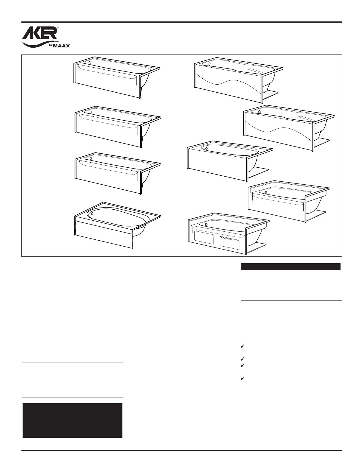
Alcove-Style (Flanged) Bath Modules
141080
SBA-3660 R
SBA-3660 L (shown)
141079
SBA-3260 R
SBA-3260 L (shown)
141352-141359
TO-3660 R
TO-3660 L (shown)
141353-141360
TO-3660 AFR R
TO-3660 AFR L
141354-141361
TO-4260 R
TO-4260 L (shown)
141355-141362
TO-4260 AFR R
TO-4260 AFR L
These guidelines are recommended by
Aker Plastics Company Inc. (hereafter
“MAAX”) for the proper installation of their
product. A careful review of these procedures
(and any referenced publications) before
starting is important in avoiding unnecessary
problems resulting in an improper assembly
or installation.
NOTE: All drawings in this publication are
typical, and may appear different than the
actual items being installed. In addition,
optional items may be shown on the units
which may not have been ordered on the
unit being installed.
ON WHIRLPOOL EQUIPPED MODELS,
A SEPARATE SET OF INSTRUCTIONS
IS PACKED WITH THE UNIT FOR THE
WHIRLPOOL SYSTEM. READ THEM
BEFORE INSTALLING UNIT!
WARNING!
NEVER LIFT OR HANDLE WHIRLPOOL
BY SYSTEM PIPING AT ANY TIME.
LIFTING THE UNIT BY THE PIPING CAN
CAUSE SYSTEM DAMAGE.
141082
GT-4260 R
GT-4260 L (shown)
Special Notes to Installer
* It is the sole responsibility of the installer
to determine, prior to the installation, the
requirements necessary for compliance
with all codes involving the unit or the
installation!
* All paperwork packaged with the unit and
any associated options or accessories
should be saved and presented to the
homeowner upon completion of the
installation!
* HANDLE THE UNIT BY THE SHELL
ONLY! Never lift any unit by attachments
or piping on the shell.
* All published unit dimensions are for
reference only. Any critical dimensions
required for installation should be taken
directly from the unit being installed!
* Any independent changes made to the
unit (or to any options and accessories
supplied with the unit) beyond those
required for normal installation can void
all warranties! (Refer to warranties for
further information.)
141081
OVA-4260 R
OVA-4260 L (shown)
141482
GT-4260 with access panel
Inspection Guidelines
A careful check of the unit should be
conducted upon receipt. Notify your supplier
immediately if any questions or problems are
encountered during this process.
DO NOT INSTALL ANY UNIT
WITHOUT FIRST ADDRESSING
QUESTIONS WHICH ARISE DURING
THE INSPECTION!
Basic Module Check
Check that the unit drain corresponds to
the bathroom drain location.
Check for unit surface damage.
Check unit color for coordination to
other bathroom fixtures.
Check for proper options and
accessories.
Whirlpool and Accessories Check
An individual system check list is included
in the assembly and operational guidelines
packaged with whirlpool equipped models
and various accessories. Refer to the listed
publications for further information before
continuing.
GUIDELINES
FOR UNIT
INSTALLATION
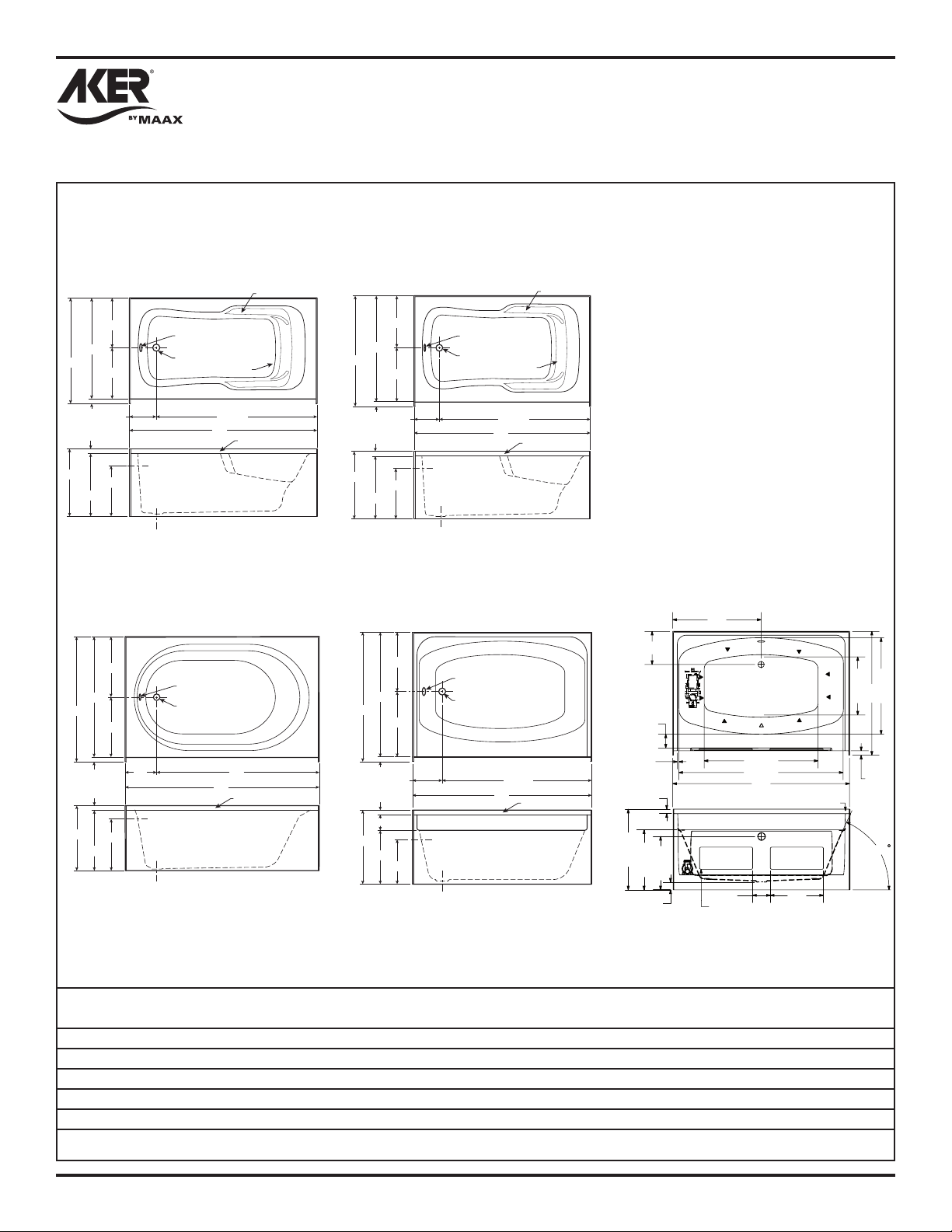
Unit Data and Dimensional Guidelines (Tolerance: +0/ -3/8 inch)
Page 2
141079
SBA-3260 R
SBA-3260 L (Shown)
15-1/4"
32-1/2"
34"
17-1/4"
1-1/2"
8-3/8" 51-5/8"
1-1/2"
"
18-1/2"
21-1/4"
Ø 2-3/8" Overflow
Ø 2" Drain
141081
OVA-4260 R
OVA-4260 L (Shown)
21"
42"
43-1/2"
21"
Ø 2-3/8" Overflow
Ø 2" Drain
Lumbar
60"
Arm Rest
Nailing Flange
141080
SBA-3660 R
SBA-3660 L (Shown)
38"
22-3/4"
17-1/4"
36-1/2"
19-1/4"
1-1/2"
8-3/8" 51-5/8"
1-1/2"
18-1/2"
21-1/4"
Ø 2-3/8" Overflow
Ø 2" Drain
141082
GT-4260 R
GT-4260 L (Shown)
19-1/4"
Ø 2-3/8" Overflow
40-1/2"
42"
21-1/4"
Ø 2" Drain
Lumbar
60"
Arm Rest
Nailing Flange
141482
GT-4260 with access panel
30"
11 1/4"
4 5/8"
"8/5 23
42"
19 3/4"
38 5/8"
55 3/4"
60"
Fastening Flange
6"
Access Panel Hole
18"
22-3/4"
1-1/2"
21-1/4"
10" 50"
17-1/4"
60"
Nailing Flange
1-1/2"
9-1/2" 50-1/2"
1-1/2"
5-1/2"
24-3/4"
17-3/4"
14-3/4"
60"
Nailing Flange
1/2"
1 1/2"
27 3/8"
2 5/8"
20 3/8"
18 1/8"
Unit Sump Bottom Dry Unit Avg. Oper. Max. Sump Floor
Model Surface Dim. (W x L) Weight (1) Volume Capacity Loading
141079 - SBA-3260 Gelcoat 20 x 45 in. 111 lb. 37 gal. 74 gal. N/A
141080 - SBA 3660 Gelcoat 24 x 45 in. 113 lb. 42 gal. 84 gal. N/A
141081 - OVA-4260 Gelcoat 23-1/2 x 38 in. 122 lb. 45 gal. 71 gal. N/A
141082 - GT-4260 Gelcoat 19-1/2 x 40-1/2 in. 116 lb. 45 gal. 65 gal. N/A
141482 - GT-4260 Gelcoat 19-1/2 x 40-1/2 in. 116 lb. 45 gal. 65 gal. N/A
1. Dry unit weight includes whirlpool system.
1 1/2"
65
GUIDELINES
FOR UNIT
INSTALLATION
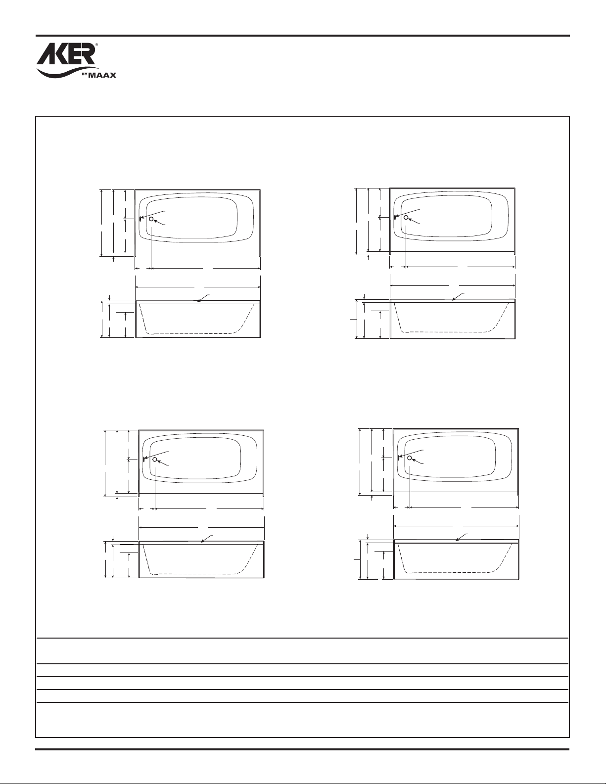
Unit Data and Dimensional Guidelines (Tolerance: +0/ -3/8 inch)
Page 3
141078-141356
TO-3060 R
TO-3060 L (Shown)
13-1/2"
30-1/2"
31-1/2"
17"
1"
1"
17"
16"
8" 52"
13-5/8"
141350-141357
TO-3260 R
TO-3260 L (Shown)
Ø 2-3/8" Overflow
Ø 2" Drain
60"
Nailing Flange
141078-141356
TO-3060 AFR R
TO-3060 AFR L (Shown)
18-3/4"
30-1/2"
31-1/2"
17-3/4"
13-1/2"
17"
1"
1"
15-3/8"
Ø 2-3/8" Overflow
Ø 2" Drain
8" 52"
141351-141358
TO-3260 AFR R
TO-3260 AFR L (Shown)
60"
Nailing Flange
33"
17"
16"
32"
1"
1"
13-5/8"
15"
17"
8" 52"
Ø 2-3/8" Overflow
Ø 2" Drain
60"
Nailing Flange
18-3/4"
33"
32"
1"
1"
17-3/4"
15"
17"
8" 52"
15-3/8"
Ø 2-3/8" Overflow
Ø 2" Drain
60"
Nailing Flange
Unit Sump Bottom Dry Unit Avg. Oper. Max. Sump Floor
Model Surface Dim. (W x L) Weight Volume Capacity Loading
141078-141356 - TO-3060 Gelcoat 19-1/4 x 45 in. 62 lb. N/A 39 gal. N/A
141350-141357 - TO-3260 Gelcoat 19-1/4 x 45 in. 65 lb. N/A 39 gal. N/A
141351-141358 - TO-3260AFR Gelcoat 19-1/4 x 45 in. 65 lb. N/A 39 gal. N/A
 Loading...