

Page 1

Catalogue
1. FRONT & BACK VIEW………………………….. p1
2. FUNCTION BOARD POSITION…………………..p2
3. SPEAKER & KEY- BOARD………………………..p3
4. I/R- RECEIVER & TUNER- BOARD……………...p4
5. AUDIO –BOARD & A/D- BOARD........………….. p5
6. I/O PORT OF A/D BOARD…………………………p6
7. POWER BOARD……………………………………p7
8. WIRES……………………………………………….p8
ASSEMBLY/DISASSEMBLY INSTRUCTION OF
9.
THEBBOARD
10 TROUBLE SHOOTING LIST………………………p13
11. BLOCK DIAGRAM…………………….…….…….p15
…………………………………………….p9
Page 2
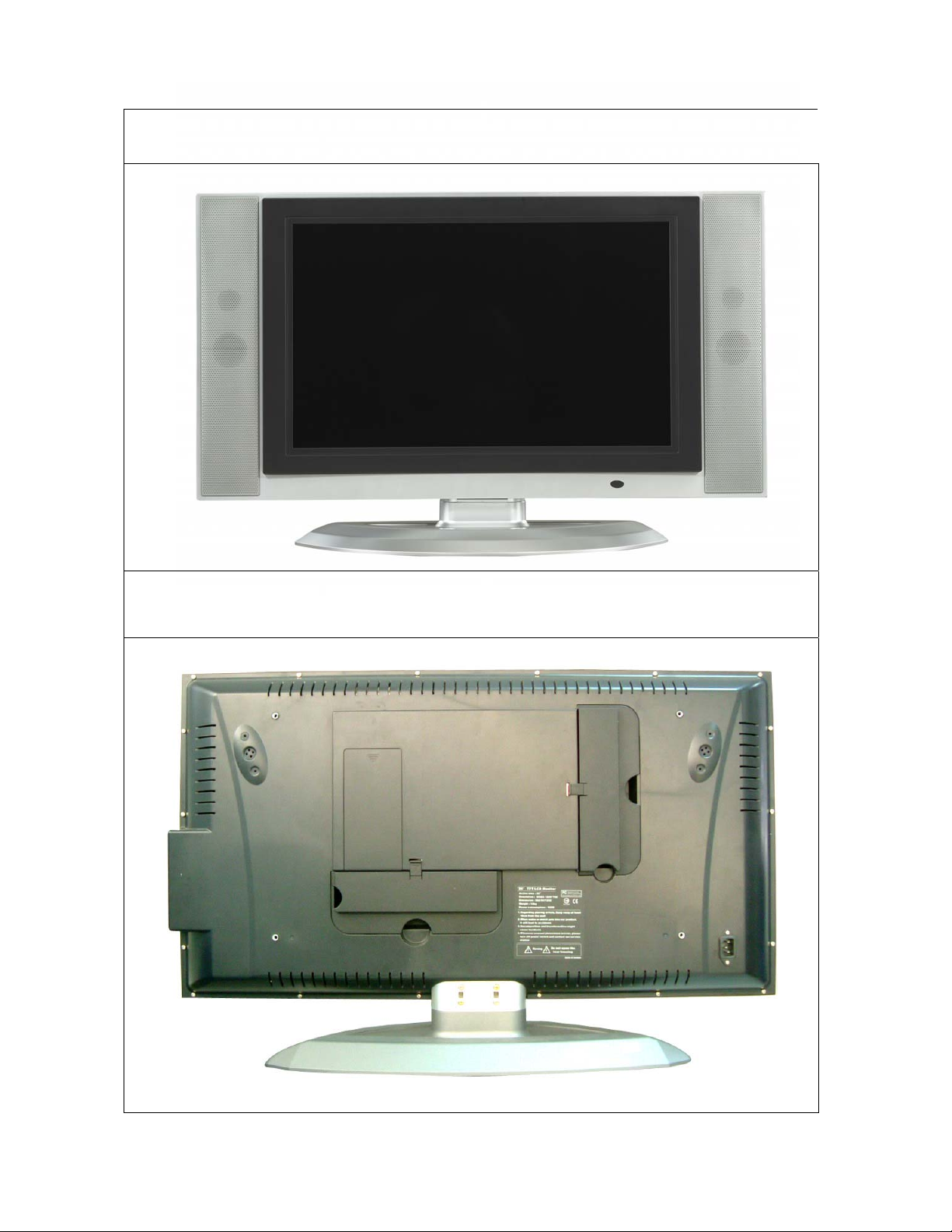
Front view
Back view
1
Page 3
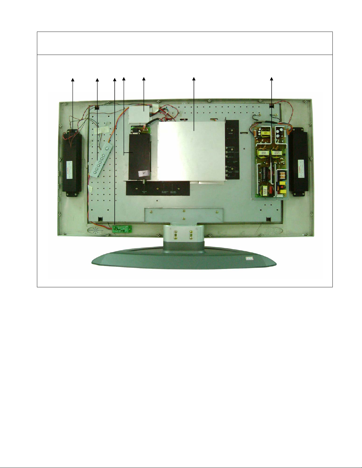
FUNCTION BOARD POSITION
12
3
4
5
6
7
ʳ
˄Ηໞ(SPEAKER)ʳ
˅Ηሽሁࣨʳ (KEY BOARD)ʳ
ˆΗદ؆ᒵ൷گሽሁࣨ(I/R RECEIVER BOARD)ʳ
ˇΗ࠰ᓳᕴሽሁࣨ(TUNER BOARD)ʳ
ˈΗଃயሽሁࣨ(AUDIO BOARD)ʳ
ˉΗᣊֺᑇۯሽሁࣨ(A/D BOARD)ʳ
ˊΗሽᄭሽሁࣨ(POWER BOARD)
ʳ
2
Page 4
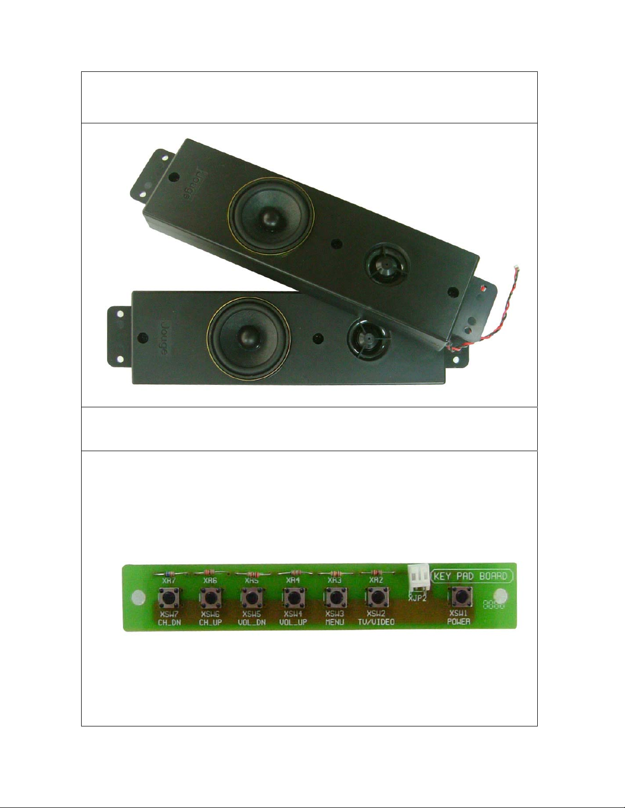
SPEAKER
KEY- BOARD
3
Page 5
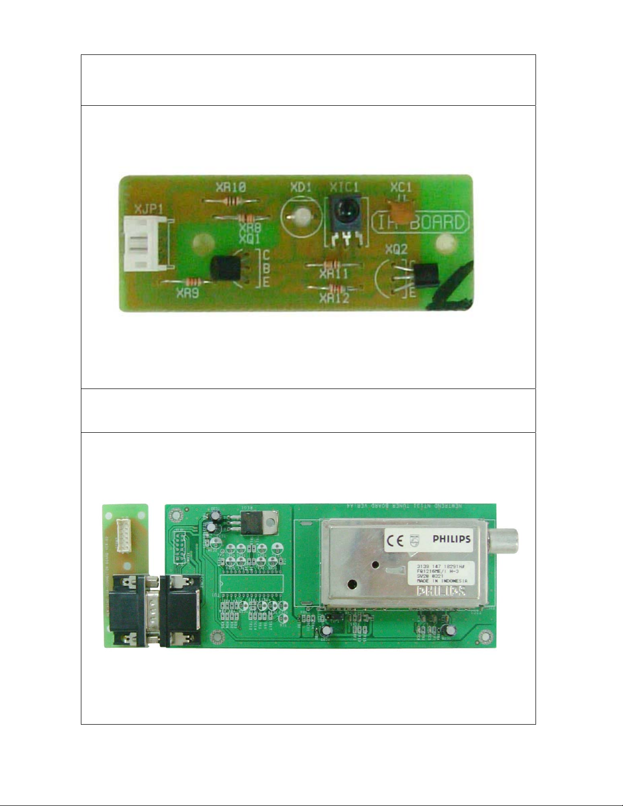
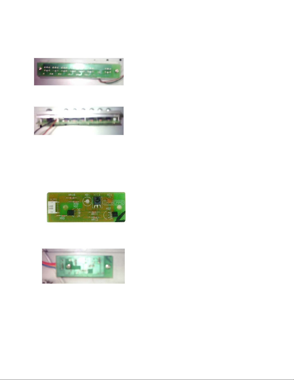
I/R- RECEIVER
TUNER- BOARD
4
Page 6

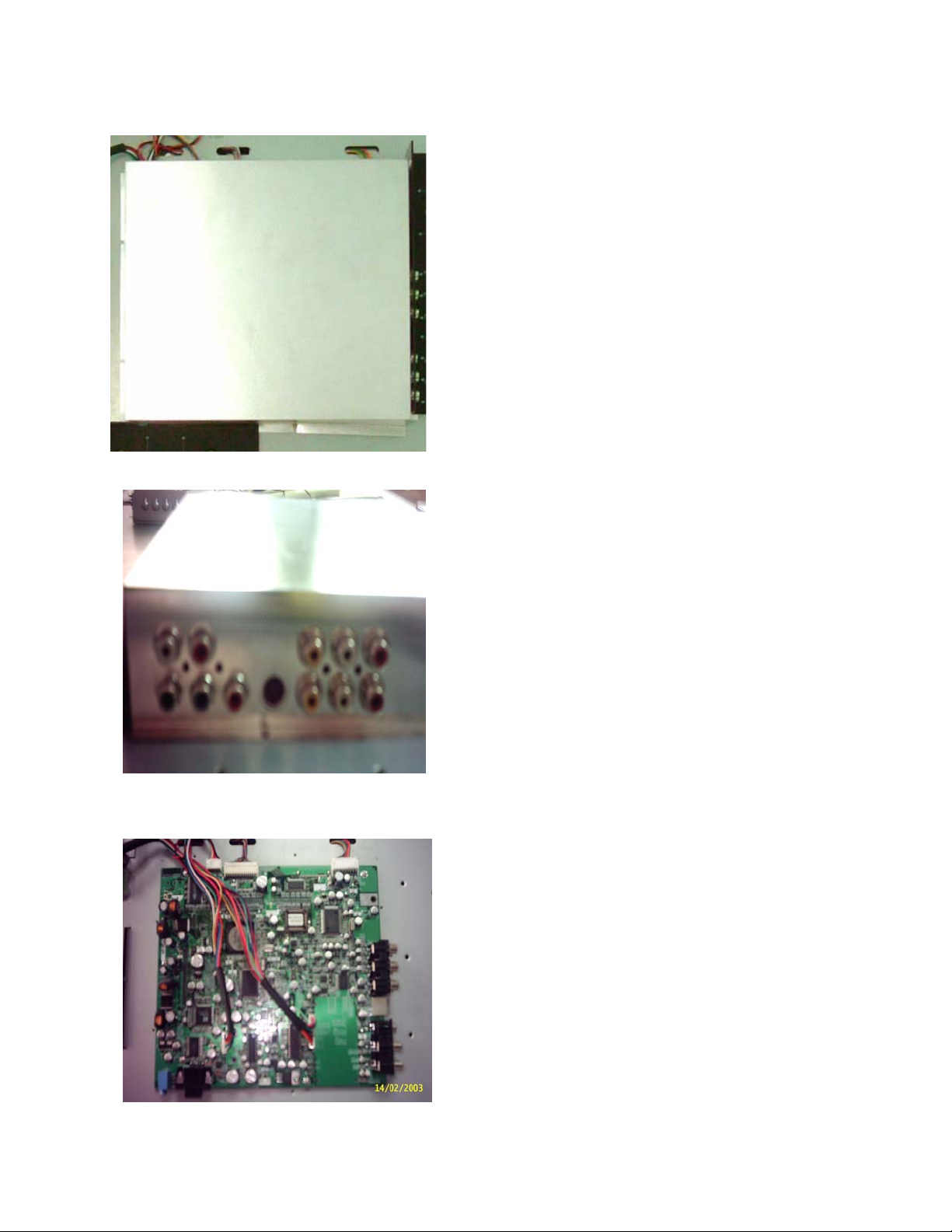
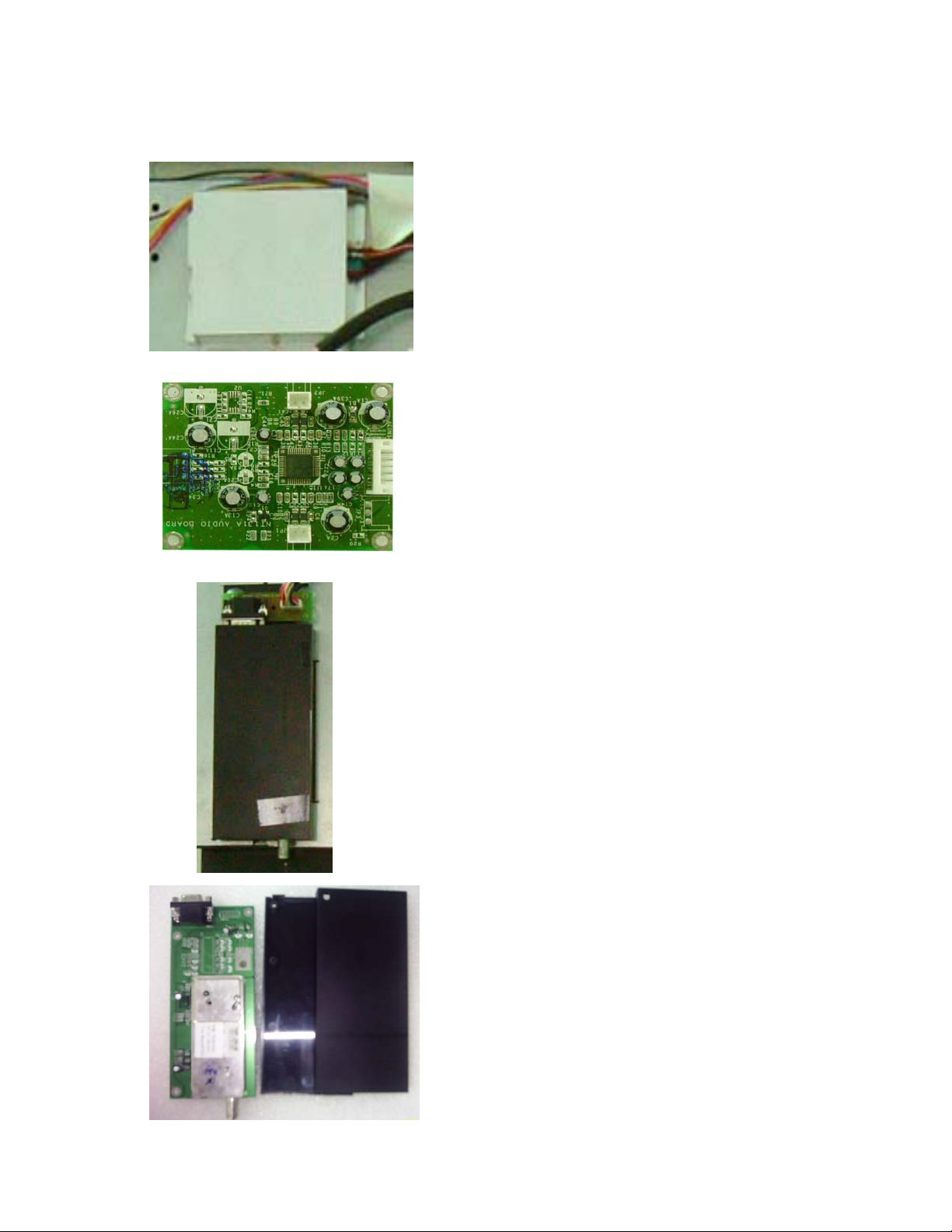
AUDIO -BOARD
A/D- BOARD (ANALOG/DIGITAL BOARD)
5
Page 7

I/O PORT OF A/D BOARD
1
2
3
4
5
6
12
11
1ΗP/A WIRE CONNECTER
2ΗK/A WIRE CONNECTER
3ΗA/P WIRE CONNECTER
4Η AV I N P U T
5Η S-VIDEO INPUT
10
9
8
7ΗSCART INPUT
8ΗT/A WIRE CONNECTER
9ΗA/A WIRE CONNECTER
10ΗDVI INPUT
11ΗD-SUB(VGA) INPUT
7
6. Y/Pb/Pr &Y/Cb/Cr INPUT
12ΗPC AUDIO INPUT
6
Page 8

POWER BOARD
24V-OUTPUT
12V-OUTPUTAC-INPUT
7
Page 9

WIRES
ˆʳ
˅ʳ
ˇʳ
ˈʳ
˄ʳ
1ΗPOWER JACK
2ΗK/A WIRE : (KEY BOARD Ù A/D BOARD)
3ΗA/A WIRE : (AUDIO BOARD Ù A/D BOARD)
4ΗT/A WIRE : (TUNER BOARD Ù A/D BOARD)
5ΗP/A WIRE : (PANEL Ù A/D BOARD)
6ΗA/P WIRE : (A/D BOARD Ù POWER BOARD)
ˉʳ
ˊʳ
7ΗI/P WIRE : (INVERTER BOARD Ù POWER BOARD)
ʳ
8
Page 10

POWER BOARD Assembly/Disassembly Instruction
STEP 1Κ
1ΕTurn off the main power switch on the back
of the set and unplug the power cord from
the outlet.
2Ε Remove the 18pcs of screws (M4*10) on
the edge of the back cover.
3Ε ˥˸˸ʳ˻˸ʳ˜˂ˢʳʳ˶˸ʳ˴˷ʳremove the
2pcs of the screws (M4*8)
4Ε Lift up the back cover but without
removing it. Unplug the power connector
lines for the Power Jack. Upon detach their
connector lines and remove the back cover.
STEP 2Κ
1Ε Unplug the AC -in power connector
lines for the Power Jack (3PIN).
2Ε Unplug the two power connector lines
for the DC 12V OUT A/P wire connector
(10PIN) & DC 24V OUT I/P wire
connector (10PIN).
3Ε Change the power board, and remove
the 4pcs of screws (M2.5*4)
9
Page 11
A/D BOARD Assembly/Disassembly Instruction
STEP 1Κ
1Ε Remove the 6pcs screws (M2*4) on the A
board cover.
2Ε Change the A/D board cover , remove the
4pcs screws (M3*6) on the A/D board cover
right side.
STEP 2Κ
1Ε Unplug the signal transmission line for the
A/A wire connector (7PIN).
2Ε Unplug the signal transmission line for the
T/A wire connector (7PIN).
3Ε Unplug the signal transmission line for the
K/A wire connector (6PIN)
4Ε Unplug the signal transmission line for the
A/P wire connector (9PIN).
5Ε Unplug the signal transmission line for the
P/A wire connector (30PIN).
6Ε To change the A/D board and remove the
4pcs of screws (M2.5*4)
/D
10
Page 12
AUDIO BOARD & TUNER BOARD Assembly/Disassembly Instruction
STEP 1Κ
1Ε Remove the 4pcs screws (M2*4) on the A
board cover.
2Ε Unplug the signal transmission line for the
A/A wire connector (7PIN).
3Ε Unplug the signal transmission line for the
speaker connector (2PIN)).
4Ε To change the A/D board, remove the 4pcs
of screws (M2.5*4)
STEP2Κ
1Ε Remove the 1pcs screw (M4*25) on the
Tuner cover
2Ε Unplug the signal transmission line for the
T/A wire connector (12PIN).
3Ε Change the Tuner board and remove the
3pcs of screws (M2*4)
/D
11
Page 13
KEY BOARD & IR RECEIVER BOARD
STEP1Κ
1. Unplug the signal transmitting line for the
Key board K/A wire connector (2PIN).
2. To change the key board, remove the 2pcs o
screws (M3*6)
Assembly/Disassembly Instruction
f
STEP2Κ
1 Unplug the signal transmitting line for the IR
receiver board K/A wire connector (4PIN).
2. Change the IR receiver board and remove
the 2pcs of screws (M3*6)
12
Page 14

TROUBLE SHOOTING LIST
ITEM
POWER
AUDIO/
SOUND
PROBLEM
NO
WORKING
HAVE SOUND
BUT NO
IMAGE
HAVE IMAGE
BUT NO
SOUND
ʳ
REASON
1.Power wire not connect
well with the connecter.
2. Battery no electric. of
the Remote control
3. Power damage.
4. A/D board damage.
1. Inverter damage or
connecter loose
2. Tuner damage.
3. A/D board damage.
4. Cable wire connect
wrong position
1. Tuner damage.
2. A/D board damage.
SOLUTION/
CHANGE PART
1.Power wire re-connect
with the connecter
again.
2. Change new battery.
3. Change new power.
4. Change the A/D board.
1. Re-connect the wire or
change new inverter.
2. Change new tuner.
3. Change new A/D board.
4. Try to connect right
position again.
1. Change new tuner.
2. Change new A/D board.
REMARK
ʳ
ʳ
ʳ
PC MODE
FUNCTION
KEY
FUNCTION
PICTURE SHIFT
& UNCLEAR
PICTURE IS
ABNORMAL OF
PIP/POP
FUNCTION
ʳ
CHANNEL UP
& DOWN NOT
WORKING
1. Set up the wrong
frequency of picture
signal.
1. Set up the right
frequency and
auto-adjust the TV.
1. A/D board damage. 1. Change new A/D board.
1. Not scan the channel .
2. Key-board damage.
3. A/D board damage.
1.Scan the channel .
2.Change new key board.
3. Change new A/D board.
ʳ
ʳ
13
Page 15
TROUBLE SHOOTING LIST
ITEM
REMOTE
CONTROL
PROBLEM
NOT
WORKING
ONLY GET
THE
CHANNEL1~12
CAN’T SHOW
ALL CHANNEL
NUMBERS ON
TV FUNCTION.ʳ
REASON
1.Battery no electric.
2.Not scan the channel.
3.I/R-receiver board
damage.
4. A/D board damage.
1. Change the Air/CATV
mode wrong function
position.
1. Not scan all channels or
you set up something
wrong with channel
memory last time.
SOLUTION/
CHANGE PART
1. Change new battery.
2. Try to scan the channel .
3. Change the new I/R
receiver board.
4. Change new A/D board.
1. Try to set up the
Air/CATV mode function
again.
˄ˁ Try to scan the channel
again.
ʳ
REMARK
ʳ
VIDEO/
IMAGE
PICTURE
NOT
PERFECT
PICTURE IS
ABNORMAL
AND IMAGE
IS BAD
SERIOULY.ʳ
1.TV cable wire quality is
bad or cable connect
not well.
2 The cable signal input is
weak.
1. LVDS cable wire not
connect well.
2.A/D board damage.
3.LCD panel damage.
1. Change the good quality
cable wire.
2. Increase to set up the
signal cleaner.
1.Re-connect the cable
wire or change new
one.
2. Change the A/D board.
3. Change the new LCD
panel.
14
Page 16

1515
BLOCK DIAGRAM
 Loading...