Page 1
,,0,
f1't'
SERVilCEMANUAT
3
PARTS
LIST
B
'roDEr
GX.635D
Page 2
0
é'
;.j-i-ii;'i
s
STEREO
Mo,)',,
SECTION 1 SERVICE
SECTION2
SECTION3
PARTS
TAPE
GX'635D
MANUAL.
DIAGRAM
DECI(
I
........43
......67
Page 3
TECHNICAL
I.
DATA
TRACK
SYSTEM
REEL CAPACITY
TAPE SPEED
& FLUTTER
WOW
FREQUENCY
DISTORTION
SIGNAL
ERASE
CROSS
CHANNEL
FREQUENCY
BIAS
RESPONSE
(1.000
TO NOISE
RATIO
TALK
SEPARATION
HEADS
MOTORS
TIME COUNTER
REAL
FF & RWD
OUTPUT
TIME
JACKS
INPUT JACKS
DIN JACK
DIMENSIONS
WEIGHT
POWER
REQUIREMENT
"0"
Hz
RATIO
VU)
2 channel
4 lrack
to 10-l/2"
Up
x0.8%
19 cm/s
cm/s
9.5
(Pitch
control: more
than 0.03%
Less
than
Less
than
Less
than 0.10%
Less
to 27,000
30
21,000 Hz
30 to
to 25,000
30
to
30
19.000
than 05%
Less
than 62
Better
than 70 dB
Better
Better than
than 55 dB
Better
kHz
100
(6):
Two GX
(3):
One
to 99
Up
using 550m
sec
120
(2):
Line
Required
(1):
Phone
Microphone
stereo/monaural
reel
-l12
(7
(3-314
xl.0%
WRMS at
WRMS at 9.5
0.04%
DIN
0.08%
DIN
13
dB at 19
Hz
13
dB at 9.5
t3
dB at 19
Hz
Hz 13 dB
aI 19
dB DIN
(at
(at
40
dB
(at
Recording
AC Servo Motor
min 59 sec,
(0
0.775V
load impedance:
mV/8 ohms
100
(2):
0.25
Required microphone
(2):
LINE
Input 2.0 mV,
x 483(H)
440(W)
(46.4
ke
2l
100V.50/60
120V,60
Hz
2201240V,50
1 lO | 120 | 220
impedance
70 mV
impedance
x 256(D)
lbs)
Hz for JPN
for US
Hz for
24 0V, 5 0/60
I
ips)
ips)
t6%)
lhan
19 cm/s
at 19
45500
at 9.5 cm/s
45500
cm/s using
cm/s
cm/s using
cm/s using
at 9.5
cmls
45500
1,000 Hz)
Hz)
1,000
Hz)
1,000
Heads,
for capstan
than
Less
(1,800
ft.) TaPe
VU)
more
mV
impedance:
l0 kohms,
mm,
& Canada
Europe, UK
Hz internally
cm/s
Two
r1.5%
than
100
system
cm/s
using
GX
Drive
20 kohms
600
kohms
O
(17.4
and
Tape
WR
WR Tape
Tape
LN
Tape
LN
Playback
Two
ohms
t
0.3V
x 10.1")
x 19'0
Australia
switchable
Heads, Two
AC Eddy
for other
Erase
current
countries
Heads
Motors
for Reel
Drive
*
Specifications
*
improvement'purposes'
For
determined with
specifications
LN-150-7 or SCOTCH #21
Akai
and design
are subject
1 tape unless
to change
without
otherwise
notice.
noted.
4
Page 4
II. DISMANTLING
OF UNIT
In
in reverse
of trouble, etc. necessitating
case
order.
dismantling,
please
dismantle
6
in
the order shown in the
photographs.
Reassemble
SCREWS A ffML KrcBS
Page 5
)
Page 6
III.
CONTROLS
1. PITCH
2.
3. BUILT-IN
4.
5. PINCH
CONTROL
SUPPLY REEL TABLE
REEL RETAINER
LEFT
TENSION ARM
ROLLER
6. RECORDING MUTE
7, REEL
8. REVERSE
9. POWER
10.
11.
12.
13,
14.
15. HEADPHONE
16.
SIZE SELECTOR
SELECTOR
SWITCH
VU METER
VU METER
(Right)
(Left}
TAPE SELECTOR
TAPE
TIMER
SPEED
START
SELECTOR
JACK
OUTPUT
LEVEL CONTROL
(Left}
SWITCH
(REC
MUTE)/TIMING
LAMP
Fig. I
17. MONITOR SWITCH
18. REAL TIME
19.
TAKE-UP
20. BUILT-lN REEL RETAINER
21. RIGHT TENSION ARM
HEAD
22.
23. RECORDING
24. PAUSE INDICATOR
25. REVERSE DIBECTION/STAND
26. FORWARD DIRECTION/STAND
27. MODE BUTTONS
MICROPHONE INPUT
28.
29. MEMORY MARKERS
30. LINE INPUT CONTROLS
MICROPHONE JACKS
31.
32. RECORDING
COUNTER
REEL TABLE
COVER
INDICATOR LAMP
MODE
and RESET
(Risht)
LAMP
CONTROLS
(Left/Right)
SWITCH
Controls
BUTTON
INDICATOR
BY
BY INDICATOR LAMP
LAMP
Page 7
IV. PRINCIPAL PARTS LOCATION
SWITCH
MICRO
BRAKE
sw906
PLUNGER SL9O3
BRAKE
RNCH ROLLER
PLUNGER SL9O2
PLUNGER SL9O4
PAJSE
TENSION
ARM(L}
REC MUTE SWITCH
REEL SIZE S1,VITCH SW9O3
REVERSE SELECTOR SWITCH
POWER SWTTCH SW90l
SW9O4
",n,.**
{.
OIJTPUT LEVEL CONTROL
PHONES JACK
VOLUME
MONITOR SWITCH
TAPE SPEED SWITCH
IIMER START SWITCH
LR
REC MOOE SWITCH
TAPE SELECTOR SWITCH
PIÍCH
CONTROL
VR9OI
TIME
REAL
TENSION
HEAD
OPERATION ELOCK
REC
MIC
rrrup
COUNÍER
ARM
BLOCK
INOICATOR
MODE
r
RÊc
l-
J VOLUME
Fig.2 Front
VOLUME
(R)
LEVEL
J
View
Page 8
REEL
MOTOR
M902 24XO-TD
RIGHT
REMO,CON JACK J9O5
VOLTAGE
SELECTOR
FUSE
TH-20rro
PC
BOARD
OPERATION
OPERATION P.C
TH-2041
ÍH-2042
VOLUME
TH-5002
P,C
PC
BOARO
BOARO
BGRD
SYS.CON PC
CAPSTAN MOTOR
M903
PRE
TH-rOr5
SCM-200
AMP PC
TH-500r4
BOARD
BOARD
Fie. 3 Rear View
Page 9
V. CIRCUIT
OPERATING
PRINCIPLES
1. SYSTEM
CONTROL OPERATION
NOT
CIRCUIT
NAND
CIRCUIT
NOR
CIRCUIT
SYMBOL
X=A
X=AE
X=A+B
TRUTH
F-tfit
loll
I'IFI
TABLE
rl
LEVEL
LOW
O=
HIGH LEVEL
I:
J
Chart-1
J
10
Page 10
0
I
ll
tl
t
3o
.3d:j*
HTiY
usF
i
a! ,oi"dado
_:i|.@
aJ4s !r ?
Í
{
ql
l=
|\;
lq
':,.+.
qEê
i^ -_.--;-È
I r r lío
!.1 r;;:,';r
t'1 ,
t.
:.-:-..
tJ::'"'. :ln
m
+,
lHs
io!
-,r:(--!J
I Íl
3i
TÍ
:l
11
u
o
*
'
-L
ri+*:rBe
ó
L"J
i3
F
$ ó"f|e
r'_f
Lt É
gI
.Íi
:tl
'l
jó51
\t.E I
t-l
-*i
-_,_l
6
oI
I
dË
=r
I
MODE
Schematic-l
STOP
l1
Page 11
it
ii
-È
."*,ffi't" i* *"
;:Tm!!!@
*A;1'
-=
,-o
-:---_..!;_Ë ^
I tgv
,
:'
Ir+' r r
q;-r+;r;+;-;JPF
.}l
toí
lLj
J
t2
"':ï'r;
l3l
*
,t:'*f;U;
.ffilMffitutu
'i:
_t-.-_--_l_
I r r lgo
!.' l;* l:;:r
:' ioq
"-
|
t,
.--:-..-;r;J_uts
i 1)-
< irr;
r
*
i
t: l
',ií
Ê:'
Ë
lH3
tdi
)
;<
t
G
E
Schematic-2
FWD-PLAYMODE
Page 12
I
T
I
|
|
|'=
I
i I lir-Q.t.'Q.r
ó
r I l-
=
",
L
- I *llr+,ir-*---. l'-t.,,
Èlii
t";
i
-l:]í:Itl
'iià,i'
:l:;
"iiài
.èàà:
.,;;i
'-;:it:
i!i:
'€q!:
li fi.>
_l li:
',rr#
tr--9\#r*
ll*!Y
| t:r l- * -
| l+'
::i
i
L!-
ï lá--'#
-ràÈllá
j..J
T
i
-
'.-,'."-lvr+
.+.
,r/\
,i:
I'
it_Y-
nit""
l*.eir
;,
:v
'"il-l"I't'i
iii
I è
:r.*
-,
'Ï'r:'"r,"iY_
I
Y
i
L
o
3o
o3
-
ai
:!Íea.ryl./1
..
!o@ w LMr
.a:/n@
'i.,+,
&?^
,.,..,. ""
t.1
'',...'"""ii
.;9
''j
-l-
Á:
6
<
trj{t
d' 3! ïÍ
t'l ;
-
-i4!x*
c, 5
:ïí )
t.
txg
i;H
fd f
t;1"-
-r*
-at
I
Schematic-3 REV-PLAYMODE
l3
Page 13
(>
l'."r
L
ó C,oirE
L..l É
3g
a
g
i:l
x! | -.1;it(:Ë
-t'
9r |
Él
^u, l
6-
t4
Schematic-4
FWD-REC MODE
Page 14
I
,
El
!:
r!:
I
6
uï
t
I
*
l;A
@
Irl
Schematic-5
REV-REC
MODE
15
Page 15
ffi*e
.*:l
:
i
^t
r,Ër
a;-*J
l
I
to
-
H
r3
i:.
tIo
t-s
I
,lii@&g
ar-) {'ll I
lÍ
t< óill
I6
'gi
4F.--..:\io
1.9
rlr,,.' ::,p
:.t
I t15 I ldr
L.1,--áÈ..
3-t
zl
Cl
,
+alC)J d
rJ3iil: ?qn
::
c:
i
lË3
:ory
*
rlg
ts
'T'l6É
{ik
.
tG
s
Schematic-6
FF MODE
Page 16
0
_ni
r
I
lËil
È"i
i;
t"
LT]iIJ
I
; ;l:9
ï=ï1
ti.F#'
'iii:
lillir
raát:
u.t;Ft;
.9íii
t:ii
"rÈ
è:3
3e
o3
HÊ
l:! |
t." I
ta Ê
l!
l':
i
I
L@_
+
ïll
!*J
i,t
o;
L
-àL
q$
..Ll !
r('li
i5=
l- l>
JÉ
grt
tÈq
::.J I z'i
@l tsr
iàil i6
1__l
o
r,;;i
El
[Áq
.;,"*.
ói'tdh*ode ,m l"ft
:rÍ
@tunffi
'ii+,
,1L--_..-l*E
l , r l:<o
ri::.1 s::::
1.2
,'l
ria
I
L,-,.ij---<@uÈ
--r, i I a
<
tÉiÈt
{ 3ifi
3a!
lË
*". ".
)
':"
ql
.,
t'
I tdi
I l
lË3
ioN
[t
luïu
f
'Rt'
qíïË
l!
--.,l
o
9;
!:
:t
Schematic-7
RWD MODE
17
Page 17
I-I. CIRCUIT CONSTRUCTION
The design
REC,
its input
with
oi M54410P
FF, RWD,
terminals. GX-635D
FWD in
place
PLAY. Pause is controlled
separate
l)
IC.
Block Diagram
until now
PAUSE and
PAUSE
of
by a
ICI M544IOP
OF
trad STOP,
preventing
REC
circuit
REV in
and
flip flop with
pt-nY.
AR as
is
constructed
place
of
a
ST
T
I
I
)
I
--'l
4.,
\)7
I
I
I
'--
FAST
FF
/.
1
@
Fig. 4
I
M544l0P
l8
Page 18
Terminals
2)
and
their
functions
Operation
input
terminals
Control
Output
terminals
Operation
3)
Terminal
terminal AR
input
activated
Name
STOP
FF
RWD
FWD
REV
REC-
FAST
FF
F}VD
REV
REC
by each
lnput terminal
Input terminal
Input terminal
Input
Input terminal
Input
Input terminal
Terminal
Terminal
Terminal
Terminal
Terminal
input
for
stopping
for fast
for rewind
with
with
with
with
with
for
for
for
"H"
"H"
"H"
"H"
"H"
terminal
terminal for recording
forward
playback in the
playback in
preventing recording
output
signal
output during
signal
output
signal
output
signal
output
signal
Terminal
operation
forward direction
the reverse
during
during
during
during
Function
direction
forward or rewind
fast
fast forward mode
forward
reverse
recording
playback
playback mode
or
mode
mode
REC/Pause mode
Chart-2
lnpul
STOF
REC/FWD
REE/REV
NOTES:
Signal
FF
RWD
FWD
REV
1. The
2. The
3. AR
When
4.
5. At the
FAST
L
H
H
L
L
L
L
input signal
is maintained
output
control
is a
"L"
=
AR
moment
FF
L
H
L
L
L
L
L
is activated
input terminal
signal
power
the
by
until
is supplied
is on,
Output
fall
the
the next
the REC
and
during
all output
FWD
L
L
L
H
L
H
L
_]-f
of
.
input signal.
output
REC output
the
will be
REV
L
L
L
L
H
L
H
is not
"L"
"H"
is
and
REC
L
L
L
L
L
H
H
when
"H",
REC
the Stop
AR
output
mode
becomes
will be
Mode
STOP
FF Mode
Mode
RWD
Mode
FWD
Mode
REV
"L".
Mode
Output
REC/FWD
REC/REV
effected.
Mode
Mode
Chart-3
Regarding
4)
Previously
first terminal
terminal
pLly
is used
Consequently,
(FWD)
the input
M54410P
was
PAUSE
was
gÍounding
not allow
will
circuit's diode
been so
has
FLAY input
input. But
for REV
the modes
and
only
Dl3
designed
and
in
PAUSE
6th terminal
the
to be
the
that
the sixth
GX-635D,
for FWD.
changed
directly
reason,
through
addition,
both
designed
from
the first
diode
F\tD and
to take
FF or RWD
if there
even
terminal
Dl3
prioritY.
(ngVt
releasing
are simultaneous
REV,
FWD
to
FF
mode
FWD.
also
is
and
For this
grounded
RWD.
into
inputs
output
In
is
t9
Page 19
VELOCITY + PULSE
WIDTH
r\
501
@
CONVERSION
Fig.5
Block
Diagram
PREVENTING CLICK
CIRCUIT
I-2.
l) When
recording must
circuit
recorded. Also when
Final Mute must operate
circuit ceases to operate
recorded.
from
In
2)
to TR28
ON.
Amp
operating
head and
When the
3)
stand-by,
base
turned ON.
potential is not supplied
is
operate
Since
electric
and
Because
fier
is
TR20 and
4)
and
When the
the
become lower than the
and
current thereby
turned
(Stop-)
This releases
and
This operation takes
circuit
out.
FOR
power
the
is in full operation
This
being recorded.
ordinary
Therefore,
only while C42
turned off. Consequently
R90.
circuit
avoided.
for
charging
turns ON. TR2l
the stop mode
recording, base
base through
P.C Board) connected
to
supply
the recording mode
power
base electric current
When
Rec head
and
turns off
TR27
current
relay
in
is
TR2l
this reason C32 and C33 are
power
on, C32
becomes
the deck
stops and
DURING
is turned
take
circuit
Rec Final
is turned ON
flows
RLI function
complete
is OFF during
is turned off
voltage on C33
and is turned
is discharged, and
ground
is effected.
therefore the click
TIMER
on for timer
place
after
else
or
power
the
before
oÍ else click
prevents
electric
R89 and
Mute relay
to TR28 collector
the signals
is effected.
is supplied
is being charged
TR27 is turned
to TR28
relay
is not supplied
C42
once
to TR28 base
only after
operation,
in this condition,
emitter in electric
is
supplied with
also
potential
from the recording
place
before
NOISE
RECORDING
recording,
the amplifier
will be
noise
click
is turned off,
the
noise
such click
cuÍrent
R90, and TR28
to the recording
timer recording
at
and
ON,
base
RLI does
with a signal.
is
charged,
through
the click
recording mode
charged.
TR20 base
on. When
ICI terminal 2
through D24.
the amplifier
noise is cut
Rec
amplifier
will be
noise
flows
RLI
@re
TR27
to
TR27
electric
and TR28
base
R89
the ampli-
noise
potential
electric
TR21
mode
not
by
will
2.THF. SAMPLE
SERVO
signals
Servo
l)
the number
either as
The motor
tions.
frequency deviation
of the
etc.,
drive circuit
motor
sion.
pulse
is
is
is
is
This
deviations
deviation
held at
is
pulse,
and
circuit.
Meanwhile,
because 112
rotation, time
the
Sample
reduced compared
deflection
For the reasons above,
to
motor
perature,
In addition,
voltage
voltage holding circuit,
voltage has
smooth
of wow
AND HOLD SYSTEM
MOTOR
of revolutions
frequency
width
in the number
is detected,
that voltage
then impressed
since
detection
revolutions,
and fewer
holding circuit,
been sharply
and stable
flutter.
&
(SCM-200)
generally created
deviations
employed
unaffected
load circuit
through
proportionately to
varies
of
converted
until
it requires
pulse
constants
and
due
generated for each
are
of circuits
Hold
circuit
the conventional
to
system.
it
minimum
chances
to the
ripple content
ripple
transport
tape
OPERATION
proportionately to
of the motor
or voltage
in
by time constants,
input signal
as
pulse
motor rotations.
to a voltage
the next servo
into
a holding
features
faulty mechanism.
of
inclusion
content of
reduced
are
GX-635D
width conver-
the motor drive
circuit
coming
can be
quick response
influence
of the
of
to result
with a minimum
shown
deflec-
uses
to the
the
The
value,
signal
and
motor
before
greatly
voltage
tem-
by
servo
the servo
the servo
in a
L|l
20
Page 20
3-3/4
+7-l/2
R4 220
t5 2,?K
e
Í
-
TR4
ÍsERVo
I
9l
!
ourPUn
lx
t-
9;
*l
cro ooilí
.-r--
:+
_2
.E
INPUT
FG
SIGNAL
ó
r.
\:
TR5
=lÈ
É
lo
lrRro *
(
/á
=[
tn
ró
3
x
I
t:
I
:
TR12
CtA
t/tOO
E
K
T_
I
in
L__
TR13
---1
r.
trt
__J
I
I
t
I
O
'_.\
ÍR6
\
a8.
",
3:
TR7
(
IR€
(
;
q
9
i
rK8
lprrrclrJoNrRoll
Át
\j
-O-
AADE
D9
qE
ry
L
I
MoToE
FÀPSTAN
Fig. 6
(d)
TR8
(e)
TRB
(Í)
TR9
(9)
rRlO
(h)
TRrl
(r)TRl2
(j)
TR12
BASE
COLLECTOR
COLLECTOR
BASE
COLLECTOR
i'
1_i*
^l t
uJ-
__L
THRESHOLD
LEVEL
Fis.7
2l
Page 21
Explanation
2)
Figs.
6, 7)
velocity
The
frequency
period
the
(a)
in
tiated and enters TR7 base. This makes TR7's
collector output as in
during the time of the negative
Meanwhile TR8 base is
(d)
like
TR8
is turned on. A waveform
width
the time
potential
Consequently, TRI I
inèreases
"tr ".
When
pulse
the
threshold
stant due to
period
the
pulse
the
velocity.
(g)
and
TRl0 and TRll. When the electric
was charged to
TRl I is ON
tionate
"e"
as its basis, Cl6 is charged
time of the standard
charging voltage
The voltage is then
pulse.
voltage
This
a servo signal
"E"
controls
As
shown
servo signal ripples are made small and a near
direct
the
time constants of the
also be made
minimized.
of the circuit operation
signal obtained
generator
of
on collector TR6. This signal is
and when it reaches the threshold
"
"11
is obtained
"T"
decreases
and
period
the
width
level.
the
that TR
width
(h)
show
"t1",
to
the velocity can be obtained.
"e"
TR13 and drives the motor.
above,
current servo signal
is shaped into a waveform in
"T"
proportionate
supplied with a waveform
from
that
TR28 is ON, TR9 base electric
TRI I
is also
"T"
"
"t1
varies according
But when
time constant.
is ON as
"
"t2
is constant
the
ON and OFF condition of
is
C16
discharged during
a signal voltage of
pulse
"e"
the
held
is supplied
"E"
is obtained. This servo
since
that
small
from
(c)
and turns ON TRl0
pulse.
the collector. During
electric
base
turned
varies
with the
TRl0 is
the
during
width
charging
until the
to the TRl2
"tt "
and
is
obtained.
smoothing circuit can
phase
lag
(Refer
the motor's
to the velocity as
differen-
(e)
with
potential
for the
ON
velocity,
to TRS's
it
on,
that
So
regardless
"t,
by using
standard
charge
the time
"e"
propor-
Next,
the limited
",
and by the
is
stopped.
hext standard
base and
"t2 "
are small,
In
addition,
factor
to
level,
pulse
time
is con-
pulse,
of the
that
with
signal
can be
22
Page 22
VI. MECHANISM
ADJUSTMENT
ADJUSTING
(U
TYPE)
WASHER
IENSION IVICRO SWITCH
GUIDE ROLLER
1.
Adjust
(d)
0.1 mm when the
by
2. TENSION
Adjust the
cam and the
0.8 mm. Check
the arm lock
the
stopper
that the loose
so
arrow mark
MICRO
screws
smoothly
ADJUSTING
LOOSE
ADJUSTMENT
(roller pulley
play gap
guide
roller is moved as
in Fig.
8.
SWITCH
ADJUSTMENT
(e)
that the
so
switch is approximately 0.5 to
micro
that
the micro switch works and that
disengages.
WASHER
(U
TYPE)
PLAY
(Refer
the
on
is approximately
POSITION
(Refer
gap
between
Fig.
to
right)
indicated
to Fig.
the
8)
screw
8)
arm
ROLLER
3.
Use the U type
(c)
and
between
should
NOTE:
to adjust
be 43 mm.
Fig.8 Roller Block
BLOCK
ADJUSTMENT
adjusting washers for screws
the
guide
tape
the
I and 3 also apply
Steps
roller.
HEIGHT
(Refer
block height: the distance
roller
to the chassis board
center
to the right
to
(u), (b),
Fig.
guide
8)
Z)
Page 23
TABLE
REEL
FIXING SCREWS
Fig. 9
FIXATION
ADJUSTMENT
NUT
Fig. l0
SCREW
L-
REEL
4.
I ) Temporarily
2) Run
.A
L-
TABLE
gap
of 15 mm between
chassis
the tape and adjust
table
so
the reel.
Adjust the height
forward. of
HEIGHT ADJUSTMENT
in the fixing screws leaving a
screw
board.
that the tape is taken
Tighten fixing screws.
the right reel
of
the
left reel table at rewind.
(Refer
the reel
the height of
table and the
in the center of
up
table
to
Fig.
the
at
9)
reel
fast
CAPSTAN
5.
Adjust
to
0.2
shaft
Tighten
condition.
SHAFT
ADJUSTMENT
by turning
degree of
mm
is moved
fixation nut
LOOSE
Adjustment
play
loose
as indicated
to maintain
PLAY
(Refer
Screw
when
the arrow
by
optimum
to Fig.
to
obtain
the capstan
adjusted
10)
0.1
a
mark.
Page 24
55os
!5og
BRAKE
LEVER
íÀ\
''*'
BRAKE
swtTcH
MICRO
o
,
\
ERAKE LEVER
Fig. I I
Fig. l3
E
€
IL
Fig.
12
BRAKE BAND POSITION
6.
AND BRAKE
Adjust the
1)
ing the screws
Work the
2)
TENSION
(Refer
brake lever to
(a)
brake
(a').
and
plunger
ADJUSTI\{ENT
ADJUSTMENT
to Figs.
position
180"
to check that the
11 to 13)
by loosen-
brake
band is not slanted.
position
3) Adjust
the
(b')
to obtain a brake tension
both brakes at stop
(Use
a 10009 spring
case
of tape.)
the
specified brake tension
diameter
In
obtained, connect
on the brake lever
and adjust.
4) By working the brake plunger
position
the
gap
the
switch body
the
of
between the brake
is
to
0.5
part
of the
mode.
gauge
for
the
springs to
microswitch
lever and the
1.0
mm.
with screws
of 550 1 50g
a reel
with 60 mm
cannot be
the other
with a finger,
(c)
screw
(b)
and
holes
adjust
that
so
micro-
on
25
Page 25
sYs.coN Pc
-
TH
r0t5
VR2
sOKB
(7-l/2in)
VRI
5OKB
(3-3l4in)
Fig. l6
10. TAPE
Set
the
the
I
,000
SPEED
Tape
Speed Switch to7-l12
-l
Hz,7
Connect a frequency
adjust VR2
50 kB until
!0.5%.
Next,
adjust
500
Hz
set the
VRI
Tape
50 kB until the frequency
t0.5%.
ADJUSTMENT
(Refer
Test tape.
12
counter to
the counter reads
Speed Switch
Fig. 16)
to
ips and
playback
LINE OUT
1,000 Hz
to
3-314 ips
counter
and
and
reads
27
Page 26
VII. HEAD
ADJUSTMENT
ERASE
HEAD
E4-241
RECORDING
HEAD
R4-241
TAPE GUIDE
HEIGHT ADJUSTMENT
NUT
PLAYBACK RECORDING
HEAD HEAD
P4-241
R4-241
ERASE
HEAD
E4-241
Fig.
17
28
Page 27
Step
Adjustment
Item
Test Tape
Supply
Signal
Mode
Adjustment
Point
Remarks
FWD Recording
2
4
6
1
Head Height
Head Height
Confirmation
FWD
Head Height
FWD
Head
FWD Playback
FWD Recording
Head Azimuth
Guide
Tape
Height
Erase
FWD
Playback
Playback
Azimuth
Alighment
Head Angle
Alignment
Alignment
Optional
Optional
Optional
Optional
8,000
3-3l4
Test
9,000
3-3l4
Test Tape
Scotch
15,000
-20
Tape
#2ll
dBm
Hz
ips
Hz
ips
Hz
Tape
FWD
FWD
FWD
FWD
FWD
FWD
REC
Tape Guide
Height
Adjustment
Nut
(a)
(b) (c)
(d) (e) (f)
(f)
(h)
(c)
that tape
does
edges
edge of
so
twist.
not
thread
of Left Ch.
height.
Left Ch. head
of Left Ch. head
the same
output,
gap
the
supply
1) Adjust
2) Do not
Upper
are the same
Upper
higher than upper edge
Upper edges
tape are
Maximum
Adjust head
change in output
applied to
Maximum output.
travels smoothly
tape over
height.
both channels.
surface
level
reel side.
both channels.
tension arm.
head core
tape.
of
that there
so
when tension
and tape
core is
core and
and
0.1 mm
is no
is
FWD Recording
8
NOTES: l.
Angle
Head
Alignment
perfect
As
properly.
out
careful
Be
2.
Use only
J,
Á
Demagnetize
ï.
tape speed
5.
Set
Adjustments
6.
exactly
are
Scotch
head
not to
tape
new
heads with
to
outlined
the same.
Tape
#211
Hz
15,000
-20
dBm
adjustments
use a magnetized driver
as level
7-1
variation is likely
head demagnetizer
ips.
l2
in
Chart
REC
aÍe vital to
4 are only
Adjust head
(c)
to
occur
before
FWD
performance,
and after
tape deck
or other magnetized
for
when
side
change
applied
using old
heads.
gap
surface so
output level
in
to the
supply
in
tape.
the
that these
vicinity
be sure
tools
head adjustment'
However, adjustments
that there is no
when tension
reel side.
adjustments
of the heads.
for REV
is
Chart-4
are carried
side heads
29
Page 28
VIII. AMPLIFIER
ADJUSTMENT
VR3
VR4
VR5
VR2
VRI
TC2
TCI
VR7
L3
*
The
letter
kB
50
50 kB
lkB
kB
l0
l0 kB
PF
80
PF
80
kB
30
"b"
following an
FWD Playback
Playback kvel
REV
Level
VU Meter Sensitivity
FWD Recording
Recording
REV
FWD Frequency
Frequency
REV
Frequency
Filter Adjustment
Bias
adjustment
Level Adjustment
Level
Response Adjustment
Response
Response Adjustment
part
number
Adjustment
Adjustment
Adjustment
Adjustment
Adjustment
indicates
(7-l12
"RIGHT
rczb
TCrb
(331a
(3-3la
in)
CHANNEL"
TC2
in)
in)
VRI I IVR2
VR2b
VRIb
Fig. l8
30
Page 29
Step
Adjustment
Item
Tape
Test
Supply Signal
Mode
Adjustment
Point
Result
Remarks
FWD Playback
I
REV
2
J
,
5
FWD Frequency
6
REV
1
8
Level
Playback
Level
VU Meter
Sensitivity
FWD
Recording
Level
REV
Recording
Level
Response
(3-3la
ips)
Frequency
Response
(3-3la
ip9
Frequency
Response
(7-112
ips)
700H2
7-l
12
Test Tape
OVU
7O0Hz7-112
Test Tape
OVU
700H27-l12
Test Tape
OVU
Scotch
Scotch
-2OdBm
-20dBm
-20dBm
#2ll
1,000 Hz 0 dBm
Recording
#211
Hz 0 dBm
1,000
Recording
Scotch
#211
1.SkHz, 15kHz
Recording
Scotch
#211
I
Scotch
1.5kHz,
.5kHz,
Recording
#2ll
Recording
l5kHz
l5kHz
ips
ips
ips
Tape
Tape
Tape
Tape
Tape
FWD
REV
FWD
F\ryD-REC
REV.REC
FWD-REC
REV.REC
FWD-REC
VR3
50 kB
VR4
s0 kB
VR5
lkB
VR2
kB
10
VRI
l0 kB
TC2
TC1
VR7
kB
30
0t0.5dBm
(0.77sv)
010.5dBm
(0.77sv)
OVU
indication
0t0.5dBm
(0.77sv)
010.5dBm
(0.71sv)
1.5 kHz,
kHz
l5
flat
kHz,
1.5
kHz
l5
flat
1.5 kHz,
kHz
l5
flat
Tape Speed
Recheck
Level.
Tape Speed
Recheck
Level.
Tape
Recheck
Level.
Recording
Recording
Speed
Recording
3-3l4
3-3l4
-112
7
ips.
ips.
ips.
FWD Distortion
9
10
1l
Confirmation
REV
Confirmation
NOTES: 1.
2.
a
J.
A
ï.
5.
Distortion
Filter
Bias
Output
Except for Steps
Set
If it does not
Unless
Level Control
Tape Selector
comply with
the core
Scotch
1,000H2
Recording
Scotch
1,000
Tape
#211
0 dBm
Tape
#211
Hz, 0 dBm
Recording
be at maximum.
should
6 and 7, set Tape Speed
Switch
is moved
to Low
intentionally this adjustment
Noise
the specifications,
FWD-REC
REV-REC
REC
to 7-l12
position.
repeat Steps
ips.
is
not
6 and 7,
L3
and re-adjust.
necessary.
than
Less
05%
Less than
0.s%
Less than
-30
dB
NOTE 4
See
NOTE
See
Mic, Line
Max.
See
4
Volume at
5.
NOTE
Chart-5
31
Page 30
IX.
DC
RESISTANCE
OF
VARIOUS
COILS
Main Motor
Reel Motor
Pinch
Roller
Brake
REV
Pause
Erase Head
Recordine
Playback
Part
Plunger,
Plunger
Plunger
Relay
Relay
Relay
Head
Plunger
Head
Designation
SCM.2OO
24XO-TD
I664TLT
124OTLT
TDS.OTA
FRL.264
BR2I I
LAB2NS
E4-24r
R4-241
P4-241
DC Resistance
Between
Between
Between
Between
BLU-RED:
YLW-BRN: 170
Pick-up Coil:
BLU-RED:
YLW-BRN: 157
700
600
696
659
1,290
I,750
665
t10%
ohms
110%
ohms
r10%
slyns
r
6665
110%
ohms
t10%
ohms
ohms
2.1
5.9 ohms
ohms
219
I l0 ohms
ohms
ohms
ohms
30
ohms
15%
X. CLA.SSIFICATION
IDENTIFICATION
P.C BOARD
I.
TITLES
AND
P.C
Board
Con
Sys.
Pre Amp
Rec LED
Volume
Fuse
Operation
Operation
P.C
P.C Board
P.C
P.C
P.C Board
P.C
P.C
OF
VARIOUS
NUMBERS
Title
Board
Board
Board
(A)
Board
(B) TH-2042
Board
P.C
P.C Board
TH-I015
TH-s00lA
TH-50018
TH-5002
TH-2040
TH-2041
Chart-6
BOARDS
Number
Direction
Reverse
Sensing
Rec Mute
P.C
Board
P.C Board
P.C Board
P.C
Board
TH-2043
TH-2044
T:H-2045
TH-2046
Chart-7
Page 31
2. COMPOSITION OF
1) SYS. CON
SENSING
P.C BOARD
P.C BOARD
VARIOUS
TH-1015
TH-2045 &
P.C
BOARDS
(4ED),
REC
REVERSE
P.C BOARD
TH-2044,
MUTE P.C BOARD TH-2O46
.a
[JrË V
dt:
Ë z\
q'q
á-êl-sil E]-
Jv:]@|3
5. tÈl
lib.-è
_t"_
i
r- " 11ï .fl
I
f/sHqÍ
8Lx
I
-it
tl
J
-J
l,
i'
1
2
;
=
IrEl
lEsl
n_^.-t
tsG@
=Ëë
Hci
l! ;
iËi 5b
-l
9@,
"''
It
i:
Page 32
3) VOLI.]ME P.C BOARD TH.sOO2
TH-5001A
soora
lrH-
TH- 500r a
]ru-soora
T
r.t
rï*1
lï
4) DIRECTION P.C
-l
vR I
5OKA
rCl
BOARD TH-2043
@
Í7h
I'W
LT
04v
sR- to50
(2ED\
lFausE-l
!i'Íht
vo@
@oc
@
o.lJ"n,tfr1nr
ty
@o
??
??
rl
ii
il
^
ÍFwpl
\zt
rwl
rÏ*-l
NEI
tLr
s)
oPERATTON
OPERATION
Fld
r^r r\ í^
\y
\?
;t
È. d.
\-/
P.C
BOARD
PC BOARD(A)
lFÁrrÉt
tly
N
?
:+
c
I
(A)
(, (,
t?
ll
ll
TH-2041
ÍH-2041
@
6\ a\
\:2
e3
(2ED)
v
& OPERATTON
E@
^
\y
I+
ïH-rot5
REI\4O CON,
ïH
REI\4O
TH- t0t5
REMO
TH- r0r5
REIVIO CON.
-
lol5
CON.
CON. JACK
JACK
JACK
JACK
P.C
BOARD
OPERATION
\5/
I
(B)
TH-2042
P.C
lsroq
/A! !t
v"+
WHÍICROSS
WHT/LONG 8LK
(2ED)
BOARD(B) TH-2042
a)
Èl
BL(
r0r5
THREI,l|O
CON,
ÍH-t0r5
REMO
CON. JACK
ÍH- rorS
REMO CON,
JACK
JACK
35
Page 33
FUSE
6)
P.C
BOARD
TH-2040
(U/T)
[a_
o
lul
l=t 3
t:l
--o
i
I
---@
|
I
I
i
ol
I
ol
eli
7\ :
aj-:ir
-*-1
álr
lo
lo
l--ír-r
r?\i
ï"i
L{
ó@i
oJ
i
I
I
|
I
o
g<
ËË
6--
EëT
ï
=tr
ï
;r
<el
NY
Ll
-T-
.F
=r
orL
ot
<gz <gz
I
@
I
I
aT__)i'@-------
I
I
I I lir@--------
I
I I ll F---------
\l-lrl
io
i
L__-
L____.
I
@@@l
Tïïl
+
}.LII
Àl
&++l
!À !À
3Y ÊY
=EE
--l- .l
ËÀ
<He
ÊÏ
ïT*l-
lrt
6à
T
!r-
i
r----------
G)r
L----------
I
@>---
^
]rx-rors
lrrrr
rvroton
nËer-
I
Rrour
I
MOTOR
REEL
J
-'ors
]rn
I
w
JO
WÁRNING: ÁINOICATES
''' -
AVERTISSEMEflT:
SAF€ÍY
SÀFETY cRrïrcal
rue[rce
ffiCOMMENOEO
MAINTENIR
óó-riipó$NrtóoNj Lt FbNCTToNNEMENÍ
óue eln oqs
PARTS
INOIAU LES
ÁIL
LE DEGRE E
PrEcEs FECoMMANDEES
CRITICAL
@ilPOSANÍS
SECURITE
COMrcNENT9
cotrcNElÍs
DE L.APPAREIL
FOR CONTINUÉD
wlrB
oNLY
D€
CRIÍIQUES
Esr cRrrtouÊ
PÁR LE FASRlcaNT
SAFETY".
MANUFACTURERS
POUR
SUREE.
REMPLACEÊ LES
NE
rcuR LA sEcuRlrE
Page 34
(JPN,
P.C BOAR-D
FUSE
7)
,
TH-2O40
l$11
t:
roi
I-L
--{@
i +
i_-l-
|
rlO
i
o
i
ori+
\t+
4"1
i I
ti
.
tActrot6oHtl
A
@
oov
lAc
I
5Ol6OHz
I
I
---1
iD
i.j
|
| | cl
.l
l
i I
ki
@-l
lo
I
"do
@
@
oo
AAL, CSA)
rzov
vr-w
T
--T->
<P-i
T.
-
aÀL,csa
,rPN o.olll.4Kv
<
oor/r2oe)
il
aL_
o
T
-]-
I
-]-
e-r-
ugl
oY
-T.
T
T
&
@
?{
i
/-T-.)
tll
t_l_J
i
@@
T?
-L-L
I;E
-]- -L
<t <l
sz
TY
LI
-T- -T-
rrF
Tï
IT
oi
T---------
rJ@**-----
|
?
|
!---------
li 11
L----------
i
<se
OY
LI
@e*-
@-*-----
-rors
rH
]
Irrrr
ÈËÈr-
J
'l
nrcxr
REEL MOTOR
J
rors
]rr-,-
]rH-rors
WARNTNG:
AVERTISSEM€NÍ: ÁIL
SAÉETY
6,{DlCÀÍES
SAFETY
ffiPLACE
RECOÍMEflDED PÀRTS
ÍÀIilÍENtR LÉ OEGRE E
CONPO$NTS DOIT LE FOilCÍIONNEMENT
OUE
CFIÍICÁL COMrc{ENTS
INOIAU LES COMrcSÁNÍS CRIÍIOUES OE SRETE,
PAR
PIECES RECOMMANOEES PAR LE
OES
CRTTICÀl
SECURITE
COMPONEilTS FOR
CONTINUEo
ONLY WIÍH IANUFÁCTURER-S
L'APPAREIL NE
O€
ESI C8IÍIOUE rcUR LA SECURITE
FABRICANT
SÁFEÍí,
rcUR
reMPLACÉR
LES
37
Page 35
FUSE P.C BOARD
8)
sw905
,rt
240V
220V
'l
TH-2040,
(CEE,
UK)
tr-
@/z4of1
uKl
rcEE,
E
(9
t
I
WARNIN6:
À!FF_.5Sf
SAFEÍY
ArNDlCÀTES
FEPLACE
RECOMMEflDED
VLN_:
MAINTEN1R
CONPOSANTS OONT LE
OUE PAÊ OES PIECES RECOMMANDEES
CRITICAL COMPONENTS
SAFElY
CRITICAL COMPONENTS ONLY WITH MANUFACTURER'S
PARTS
r\OOU
^ L
LFS.OMPOSANTS
LE DEGRE
CRtTTOUES OE SUnetr.
SECURIÍE
DE
OE L'APPAREIL
FONCTONNEMENT EST CRITIQUE POUR
PÁF LE FAERICÁNI
]rr-rors
Irrpt
nËrr- uoron
-J
RIGHT
I
MOTOR
JREEL
rors
]rn-
FOR CONÍ|N!€0 SAFETY,
pOUn
REMPLACER
NE
LES
LA SECURIÍE
%
Page 36
SECTION 2
J
PAFITS
TABLE
RECOMMENDED
HEADBLOCK
MOTOR(SCM-200)BLOCK
R.EELTABLEBLOCK
ROLLERBLOCK
POWER
MECHA ASSEMBLY
P.C
(1)
(2)
(3)
(4)
AMP ASSEMBLY
9.
FINALASSEMBLYBLOCK
10.
LISTOF
11.
INDEX
SI.JPPLY
BOARDS
CON
SYS.
PRE AMP
voL.P.CBOARD(TH-5002)BLOCK
REC,LED
INTERCHANGEABLE . . .
SPARE
BLOCK
BLOCK ..
P.C
BOARD
P.C
BOARD
P.C
BOARD(TH-50018)BLOCK.
BLOCK ....d)
LIST
CONTENTS
OF
PARTS LIST. .
(TH-l0ls)
(TH-5001A)
BLOCK . . .
BLOCK . . . .
. . .46
.......48
...50
....
......5I
....52
. . .54
.. ...56
.....58
. .s8
s9
.......s9
...s9
.......62
. .&
.......65
Resistor
FOR
LIST
and
Capacitor
SERVICE
whhh is not listed
PARTS.
in this
parts
list,
please
refer to COMMON
43
Page 37
parts
This
\ilhen
ordering
How
to read List
-
The reference number
parts
I r-This
I I
I
|
t
Ref
No.
l2-ll5x
l2-ll6
12-ll7x
l2-r
12-l19
The
of
5.
Please
6.
The
parts
Both
7.
Parts
FLYWHEEL
8OO425
244506
244754
l8 251324
253080 Main
symbol numbers
Components
utilize
shape of the
shown,on the Electrical Parts
the kind
determine
It
is necessary
8.
Utilize
finding
separate
parts
HOW
list is compiled by
parts, please
list.
This number
in that figure.
I
r--A
2- | I 5 i
No.
sepaÍate
of
where a parts
"Price
Price
Description
BLOCK
FlywheelBlockAssy.Comp.
Flywheel
Felt, Flywheel
Main
Only
Metal
Metal
shown
of the
Schematic
"Common
parts
and
part
and installation position
number
of
all
listed at
3 above).
List for
is to
utilize
TO
USE THIS PARTS
various
describe
individual
parts
corresponds with
corresponds
number
corresponds with
"x"
small
in rhe Photo
#I3
Case
on the P.C.
Board
Diagram or
for
List
parts
name, etc.
Table of
is listed,
to
find the
Íight of
Parts"
Parts Number.
parts
to determine
the reference
blocks
number,
serial number,
illustration
with
the Figure
indicates
lllusrration.
or
Schematic
manufactured
(not
*13
RDr;
RD-233
RD-275
RD - 236
RD-237
list
can
Service Manual.
Service
Parts" for
can be
P.C.
Board.
can
utilize Parts
number
number.
LIST
based on
photo
or
Number.
the
individual parts
the inability
Diagram Number
required
be
confirmed by
be
determined
Index
This
in the
for
matched with
Resistor
at end
can be accomplished
Parts
price.
assembly
and
process.
model
number
number of that
index
to
show that
particular
of individual
part.
parts
order)
the
Composite Views
Parts orders.
comparing them with
Parts
by the
of
Index.
The
most simple
Parts
(meaning
Number.
List.
in detail.
particular
number
by
using the
of ref.
method
part
the
To
no.
of
CAUTION:
l.
2. Please
3.
.
INDICATES
A
SAFETY
CRITICAL
PARTS.
EMENT: A II
DEGRE
TNUQU
DE SECURITE
FONCTIONNEMENT
MANDEES
PAR
When placing
an order for
description. There
parts
cannot
be shipped
be careful not to
part
a
different from
Because
(Basic
parts
Parts
number
List)
reference.
SAFETY
CRITICAL
COMPONENTS
LES
COMPOSANTS
DE L'APPAREIL
EST
CRITIQUE
LE FABRICANT.
parts,
are instances
or the
make a mistake
the one ordered
parts
and
may be
partially
COMPONENTS.
ONLY
CRITIQUES DE
NE
POUR
be
in
wrong
unit
changed,
sure to list
which if
parts
will
in the
may
be delivered.
supply
FOR
any of this information
be delivered.
parts
in the
please
CONTINUED
parts
the
no. If the
Preliminary
use
this
WITH MANUFACTURER'S
SURETE. POUR
REMPLACER
LA SECURITE
LES
COMPOSANTS
PAR
QUE
no.
model no.,
is omitted,
parts
no. is
Service Manual
parts
SAFETY,
list
for
REPLACE
RECOMMENDED
MAINTENIR LE
DONT LE
DES PIECES
and
in error,
future.
all
RECOM-
Page 38
INLET SYSTEM
AC
J
This model
specific
because the
Please
before.
type. By
note,
is equipped
the AC
model is
however,
provided
that certain models
with an
CLASS
AC INLET
INLET SYSTEM,
with socket
I
SYSTEM.
AC
exclusively for
are not equipped
Please
(mains)
AC INLET
Picture l
AC
to be
installed
on machines
to the AC
refer
cord can be connected
(mains)
AC
with this system
cord on
its main body.
SYSTEM CHART
.r0 This mark
tion will be attached to
Danel
raÁ-:r Í---,-l-f-t
(O((o
\-Sry--/
INLET
INLET SYSTEM CHART below
to
disconnected
and
and has a built-in
CLASS II
indicating double insula-
o))O)
from the model
(mains)
AC
machine's rear
I llF=l
Ll_LJ--r
for the
coÍd
as
Parts List
Class
Class
Connects to
machine's
AC lnlet
for AC
Standard
I
II
(mains)
CEE
BEAB
SAA
UIT
CEE
BEAB
SAA
U/T
ntr
cou
,\sr
v \ -\//
O,/
Denmark
ffi,'
*t
Australia
differs
to wall
Cord Set
les
v)'l' v
'\J,.
,,,
according
socket
u.K.
Cord Set
Set BEAB
Cord
Cord Set
Cord Set
Cord Set
Set BEAB
Cord
Set SAA
Cord
Set
Cord
Picture
(mains)
AC
cord
Description
(3
CEE
(3
(3
SAA
(3
U/T
(2
CEE
(2
(2
(2
U/T
2
cores)
cores)
cores)
cores)
cores)
cores)
cores)
cores)
Connects
machine's
AC Inlet
Type of
to
AC Inlet
3P
3P
3P
3P
2P
2P
2P
2P
the
Most of
European
ies
ntr
cou
Australia
diÍfers according
to wall socket
Parts No.
F.W302993
8W302994
8W302996
F'W302646
EW638144
EW302995
8W302991
EW302899
45
Page 39
1. RECOMMENDED
SPARE
PARTS
LIST
parts
Because,
Recommended
if the
Parts No.
listed below are on hand, almost
Parts
Spare
Items.
84308262 Sys. Con
8A308263 Sys. Con
84308264
BA308275
8A308296
8H308217 Head
8M308310
Sys. Con
Pre
Ar4p
Pre
Amp
Block Comp. GXó35D
Motor
8M587518 Motor
BRs87553 Reel
8T308918
BT30891
9
BT30892
Table Block Comp. TE
Power
2\
Power
I
Power
I
Power
I
82308221 Roller
82308228 Roller
F.D698826 LED
ED283
1 38 LED GL-3PG1
ED303005 LED
ED30894s
8D313623
8D309069
ED30895
ED308941
8D308952
ED308953
ED306109
8D224550
EI308936 IC
I Zener Diode WZ-|2O
SR-IO5D
GL.3PYI
Silicon Diode
Zener
Diode HZ22-3
Zener Diode
Silicon Dode
Germanium Diode
Germanium
Silicon Diode
Silicon Diode 10D4
M544IOP ICI
EI43066r IC M532OOP
E1633960 IC
EIs73840
Er306141
EM309051
EM309050
M532O2P rc4
IC M532O4P
IC
LA417O ICI
vu Meter vu-50-003
vu Meter vu-50-005 JPN
EP309056 Plunser
EP3 10448 Plunger
FP310447
Pluneer
EP309061 Relay FRL-264
EP308949 Relay
EP308973 Relav
Description
P.C
Board
Comp. GX-63sD
P.C
Board
Comp. cX-635D
P.C
Board
Comp. cX-635D
P.C
Board
Comp. GX-635D
P.C
Board
Comp. cX-635D
Block Comp.
Block Comp. 24XO-TD TE
Trans.
Trans.
Trans.
(SCM-200)
THT-I U/T
GX-635D
(Take-up)
THT-2 JPN
THT-4
Trans. THT-3
(L)
Block Comp. cX-635D
(R)
Block
Comp. GX-635D
SVBl0-100
HZ6B-2
SVBl0-200
(Stop.
Type)
lK34A-LR
(Home.
Diode
W03B
TDS-07A
Type)
|664TLT
I240TLT
BR2l I
LAB2NS
any repair can be accomplished, we suggest that
Note
(U/T) (JPN)
(CSA) (AAL)
(CEE) (UK)
(U/T)
(JPN,
CSA,
AAL)
(CEE) (UK)
AAL
CSA,
CEE, UK
lK34A-LH
1c2,3
IC5
U/T,
CSA, AAL, CEE,
you
stock
these
UK
46
Page 40
Parts
No. Description
Note
ES3
I 3792
8S3089 I 4
ES3089
I 3
85308925
F,5313622
E5309059
8S3090s8
8S309094
E530143s Slide
E5308984
83308983
E3301436
ES301
5 Slide
71
85306292 Leaf
ET3l249l
8T301349
stice sw.
A
Push
SW.
Rotary
Push
SW. SUF12
Push
2\
Push
I
Push
I
Slide SW. SL|3-6-6-2-2-B
SW.
Push
SW. SUF44
Push
SW.
Slide SW. CL-206E
SW. SSB02214
SW. BSW-86
Transistor
Transistor
ET308947 Transistor
Transistor
8T522268 Transistor
Transistor 2SC945L
ET352146 Transistor
8T308978 FET
2SK68
ET31 1336 Transistor
Vol. VMl0E 1 kB
Semi-fixed/Vol.
Semi-fixed/Vol.
Semifixed/Vol.
EV30s636 Semi-fixed/Vo1.
8V306989 Semi-fixed/Vo1.
8V301 437
EV308966
8V308995
Axial2
Sinele
Semi-fixed/Vo1.
Double Axial2 Throw Vol. DM20R 50
TSSor2l83 CEE, UK
SUFI2
SRUI0235
SW.
(w/o
JP-27
SW.
JP-27
SW.
JP-24
SW.
CL-2108
J-K2023
(B) (C)
25D794
2SC2l30
2SC458LG
(P) (a)
(a) (R)
(G) (H)
(Q)
(Q)
(D)
&)
(H)
Vl8K3-6
Vl8K3-6
D8 Axial Type 10 kB
D8 Axial Type 50 kB
D8 Axial Type I kB
Throw Vol. GM70R-715 l0 kBx2
D8 Axial Type 30 kB
HE308149 ERASE HEAD E4-241
HP308146 PB HEAD P4.241
HR308148
M8308701
REC HEAD
Counter Belt
MP424023 Pinch
Roller
R4-241
KD
D=37
lavel) U/T,
CSA,
CEE,
YC408
(4US)
50
kB
(4US)
20
kB
kAx2
JPN
AAL
UK
Page 41
2. ILLUSTRATION
25_tp
OF HEAD
BLOCK
w
48
Page 42
HEAD BLOCK
2)
$
Parts
ft:l'
2-1x
2-2
2-3
2-4
2-S
2-6
2-7
2-8
2-9
2-1O
2-ll H8309408
2-12
2-13
2-14
2-15
2-r6
2-17
2-rB
2-r9
Z-zOx
2.21
2.22
2-23
2-24
2-25
2-26
2-21
2-28
2-29
2-3O
2-31x
2-32
2-33x
No.
8H3O8271
2W273914 Spring
ZS4|32O1
H252858r Tape
MHs78957
2W265522 M3 Nut,
2G466312
HZ3O|177
HB308681
H8309407
2G303300 Angle Adjust Spring
HB308685
256085O1 Screw,.pan
ZS4|'74O1
HA309409
He:oS+tO
HA308686
H4308ó87
HZ3O94Il
HE308149
HR3O8I48
HP308l4ó
HZ3O|366
23460440 Screw,
25608095 Screw,
2W309055
25201778 Screw,
ZW66a62l
EJ310390 4P
EJ310391
EJ310392 7P
EJ3|O446 7P Micro Connector
Head
Sctew,
Tape Guide
Angle Adjust Spting
TaPe
Head Sub Chassis
ER
ER Head Base
PB Head
Screw,
ER Head
ER
PB Head Ansle
PB Head Angle
P.C Board Terminal
ERASE HEAD
REC HEAD
PB HEAD
Head
Washer
M4 Spring
Micro Connector
4P Micro ConnectoÍ
Micro Connector
Description
Block Comp.
Washer, M4
pan
head 4x8
(A)
Guide
Prop
#2
(C)
Guide
Base
Head
Base
head
pan
head 3xl0
Angle
Head Angle
R4.247
P4-241
Shield
pan
head
head 2x5
Pan
D3x6x0.5t
pan
head
Washer
GX-635D
(E)
(A)
(B)
(B)
3xl2
(A)
(B)
(A)
(B)
Plate
84.241
2x4
(Black)
4x8
(Black)
w-H8004-020
w-H8004-02 r 26,6-30?
w-H8004-01
w-H8004-0r 7 26-6-309
ó 26-6-308
Schematic
No.
ND
0006
TD 0003
BS
0018
NE-0212
TH 0002
TH-0007
TH 0007
RD 55
TH
0005
TH-0008
TH-0008
TH 0006
TH 0006
TH-0009
NE-0211
26 6 306
c
When
ordering
parts,
Please describe
Parts Number, Description, and
Model Number
in detail.
49
Page 43
3. TLLUSTRATION
OF MOTOR
(SCM-200)
BLOCK
1
@-
2
ii
10
9
iL
MOTOR
3)
Pef
1i;.
x BM3O83l0
3-1
3-2 2W59"1543 Thrust
3-3
3-4
3-5 SKs 97633
3-6x
3-7
MV368886
3-8
M2585900
3-9
M259769O
3-10
1 2W4r3218
3-1
3-12 25413201
(SCM.2OO)
Parts
No.
2W6O5698
2W597622
25608308
82308315
Motor
Thrust Washer
Felt
Washer
Cap
Screw,
Detection
Steel Ball
Shaft Support
Ball Holder
Nut
M5. #1
Screw,
BLOCK
Descripr
ion
Block
Comp.
(scM-200)
Washer
(B)
pan
head
3xl
Gear Assy GX-635D
D3
pan
head 4x8
8, w/washer
GX-63s D
Schenatic
No,
KJ-?009
KJ 2009
KJ.7022
Kl ?023
LS-1203
KJ
?029
50
When
ordering parts,
Please
describe Parts
Number,
Description,
and
Model
Number in detail.
Page 44
$
4. ILLUSTRATION OF
REEL
TABLE BLOCK
s
When ordering
parts,
Please describe
REEL TABLE BLOCK
4)
Parts DescÍiption
ft::
4-lx 8R587553
4-2 MS34200o
ZGS4O6|7 Clamper Spring
4-3
M't534611 Reel Clamper
4-4
ZW27OO88'E'Ring
4-S
MTs34688
4-6
ZS4l961O Screw,
4-'l
4-8 MT43ó86O
4-9 2G317496
25424056
4-lO
MOTOR BLOCK
4-11, 8M587518
Parts Number, Description,
Reel Table Block Comp.
Reel
Shaft
Reel Table Rubber
Brake Cloth Comp. MR
Felt Tension
Screw,
Motor Block Comp.24XO-TD
and Model Number in detail.
1.9M
pan
pan
TE
head
3x12
Spring
head 4xl0
(Take-uP)
TE
Schenatic
No.
3R 108
TW-2096
TW-2032
6-r-9
TW 2033
MR-269
MR-260
<1
Page 45
5. LLUSTRATION
2.7
28
2.9
2I
26
20
24
19
16
11.
23
OF ROLLER
BLOCK
23
22
i ó --,)
-..-
\\-
-;-
9-
\
m
-
8
5
52
Page 46
5) ROLLER
BLOCK
O
Parts
ft:l'
5-1x BZ3O822'|
5-2x
5-3 SZ3O87l'l
5-4
5-5 52308718 Arm Damper
5-6
5-'7
5-8
5-9
5-10
5-l I
5-12
5-13
5-14
5-15
5-16
5-17
5-18 25422965 Screw,
5-1 9
.
5-2O
s-2r
5-22
5-23
5-24 ZW3Oa927 Washer Dl0.2xl4x0.5r
5-25x
5-26
5-27
5-2a
5-29
5-30 MR3o87l5
No.
Roller
82308228
25417216
EW3O8922 Washer D9.2x
ZW3O2a96 Nut D9xl1x2t
ES308929 Micro
25308931
ZW55069'l Washer
2G3O8722 Lock
2w308930
ZW27o1Or
25608321
2Gs67685 Azimuth
MI30870? Tension
EZ3OA7|2 Insu. Bush TH 2008
H2308?lo Tape Guide
M2535O72 Insulator Bush
HZ3oa'tO9
25479474
2G3r2399
2W313822 Washer
ZW3O'|294
MR30871 3 Counter Roller TH-2009
M83087r4 Roller tselt
2W308928 Washer
Roller
Arm
Screw,
Screw,2.6xl8
washer
'E'Ring
Screw,
Tape
Screw,
Spring
'C'Ring
Roller
Description
(L)
Block
(R)
Block Comp.
Base TH 2013
Damper
pan
head
l5x0.5t
VV-S
SW.
Spring
Guide
(Pan)
(SPC)
D2.9x7.4x0.51
D4.2x9x0.25t
3M 6-l-9
pan
head 3x6, W=8
Spring
Wheel
pan
head 3x15
(B)
(A)
(A)
pan
head 2.6x5
-3.2/0.2'31
Tl
D10.2xl4xO.l3t
STW-lo-C-3
D2.4x7xo.2t
(only
Pulley
Comp.
3x4
(ALP)
(P=0.7s)
(PBP)
(l
)
.s
(Polyslider)
(Teflon)
R)
GX-635t)
GX-635D
(Nylon)
schenatic
TH-2011
25 I
SE
TH 2018
CP
0040
TH'2001
TH 200?
TW'2075
TH 2006
613
TH
2010
TH 2011
o
When ordering
parts,
Please
describe
Parts Number,
Description, and
Model Number
in detail.
53
Page 47
6.ILLUSTRATION
OF POWER
SUPPLY BLOCK
/-*
,(e)
v
é
I
I
I
Page 48
POWER
6)
SUPPLY
BLOCK
t
$
T
Parrs No.
ft:l'
P.C BOARD BLOCK
FUSE
6-l x
EC5
5l 160
Ceramic/C. l)B82 t
A
o.01pF
EC294l l8 À Ceramic/C.
6-2x
EC3ol320 A MP/Cl. 4700PF
6-3x
POWER
BT3o89l8 À
6-4
BT3o89l9 À
6-5x
BT30892
6-6x
BT30892O
6-'7x
2W308916
6-8x
2543527 3 Screw,
6-9
ZW41326'l
6-10
EC249592 MP/C. 4+4pF 25OWV
l
6-r
25325495 Tapping
6-12
E!3o'12'74
6-13
ZS42l740 Screw,
6-14
b:.Z'631945
6-15
Flw3oó42 8 A
6-l 6
F]W3O6427
6-17x
EW305691
6-18x
8J301513
6-19x
ES3l
6-2ox
6-2lx
6-22x
6-23
6-24
6-25
6-26
6-27x
6-28x
6-29x
6-3ox
6-3lx
6-32x
6-33x
6-34x
3?92
25447761 Tapping
25422076
EJ262732 À Socket
h'.J249467
2S463353 Tapping
EIr56368l
E!'563703
EF6l65s5
baF57s932
UF-659698
Et'308923 ÀFuseSS-2
11F68331 3
F)F593706 À
EF623l
lpl.'
o.o
ST'PPLY
Power Trans. THT-I
Power
Power
I À
Power Trans. THT-3
À
Washer D4.5xl0xlt
Flange Nut
Remo. Con
9P
Strain
ACI Clord
ÀACl
AACCoTdCIUL(CSA,AAL)
2P
À
Slide SW. TSS0 | 2 | 8J
À
Screw,
A Voltage
F-use
A
Fuse
A
AFuse
l-use
À
F'usê
A
Fuse
À
Fuse
Fuse
o3 À
Description
(Z)
1.4
(I))
I 2swv
P.C
BOARD
Trans. THT-2
Trans. THT-4
binding head 4x I o
M4
Screw
pan
head 3x8
Relief
(u/T,
(U/T)
(JPN)
Cord
(CltlE.
Inlet
Screw
pan
head
(Volt.
Selector
Screw
lA
25oV
2,{ 2s0V
l.6A
o.8A 25oV
SS-2 2A 2sOV
SS-2 O.8A 250V
(SEMKO
s00mAT
(SF)MKO
NA
(Uir,
kwv
I)PNó600
(CSA,
(M)
(cI,lE.
sOwv
2
(U/T)
(JPN)
(csA,
(cEE.
(BR)
3x6
#2,
Socket
(Black)
SR-4N-4
JPN, CSA,
UK)
((lF-!.,
3x6(BR)
#2,
(Black) ({lE!1,
((lEt',,
3x5
Selector)
(U/1
3x8(BR)
#2,
(Black) (U/r)
(U/T)
(U/T,
JPN)
(U/T,
2s0V
(U/T,
(csA.
l.6A(CSA,AAL) 39 I56
(csA,
T Type)
(CEE,
T Type) I AT
(Cll1I1,
Schematic
uK)
UK)
uK)
UK)
UK)
UK)
UK)
)
24555
24 5
24 I r22
38 4 667
38 4
38 4 670
38 1 669
24 I 116
3t 1 223
26364
26363
26365
3l I 200
25 3 148
3l I 190
42 I 109
39 I
39 l's0
39 I 50
39 I 56
39 156
39 153
39 I 53
JPN)
YM
AAL)
AAL)
AAL) 27 19
(U/'l
)
JPN) 39 150
JPN)
AAL)
AAL)
70
668
50
When
ordering
parts,
Please describe Parts Number, Description, and Model Number in detail.
55
Page 49
7. ILLUSTRATION
MECHA
OF
ASSEMBLY BLOCK
56
@
I
i+
Tr
Page 50
7) MECHA
ASSEMBLY
BLOCK
{,r
Ref
Parts
No.
No.
Description
COUNTER BLOCK
7-l
j-2
7-3
'7-4x
'7-5
'7
-6
'7-'7
MC3O8242
EV3o89i?
PAUSE
EP3O9056
255923'78
ZW3
ZG3O8134
ZWz1OOa8
Counter
vol.VMloE
PLUNGER
Plunger
Screw,
13593 Washer (PBp)
Joint
'E'Rine
Part
BLOCK
TDS-O?A
pan
head
Spring
l.9M
MP499-O7
I kB
I)5.1x1o.3x0.5t
SW. BLOCK
7-B F]S3O89l4
'l-9
FlS3089l3
7-lO 25422076
't-r1
ED69882ó
7-12 ES30892
PR PLUNGER
7-13 EP3lO448
7-14 2W678'723
7-1s 2W29O283'U'Ring,2.85M
'l-16
MB428343
7-17 ZW27or23'E'Ring,4M
'7-l8x
2W26O076
'l-19
2W42O682
7-2o 2G3O8728
1-21
MS5 27591 Pinch
'7-22
2W413278
'7
-23
25444262
Push
SW. SUltl2
Rotary
SW. SRUl0235
pan
Screw,
LI.tD
SR-losD
Push
5
SW. SUF
BLOCK
Plunger
t664TLT
Washer
l)6.2x
Stopper Ruhber,
(Nylon)
Washer
(Nylon)
Washer
P
Spring
Roller
Nut
M5.
#l
Screw, binding
head
I 2
l3xo.2t
Shaft
2.6x3
3xs
(Teflon)
KD
D6.1xl0x0.5t
D4.2x9x0.5t
head
4x I
8
Schematic
9167
36634
44
I 105
TH
2031
619
25
5-301
25
6 161
45 15 16
25 5
304
44 I
106
6ll
KD
1088
619
TH
2025
ND 1030
Ref
Parts
No.
No
7-58x ZS60832l
7-59 2G30r340
7-6Ox ZW27
'l-6lx
-62
7
0156
ZW27OlOl
MP42402
7-63 2W376391
'7-64
zSS2768l
't-65
ML308904
7-66 ZW580l
7-67 ZG3t
'7-6ax
7-69
7-i
Ox
'l-7lx
-'|
7
2
3099
ZSJO9096
MB308?O1
ZW3304l2
2W330423
2c6'7
24'7 a
pan
Screw,
Pinch
Roller
'E'
Ring 6M
'E'
Ring
Pinch
3
Washer (Polyslider)
Pinch
Shifter
Guide
?3
Coil
Screw,
Counter
3M
Roller
Roller
Slide
Washer
Spring Tl-8.O/0.5-3
3xó
Belt
Adjust. Washer (U)
Adjust.
Washer (U)
Brake
Spring
Description
head
3x6,
Spring
KD D=3?
D6.lxl0x0.l3t
Set Screw
Part
(l'an)
w/Plug
W=8
I.5
D4x I 3xO.l
D4x
13x0.25t
3t
Schematic
NE
223?
619
619
KD 1084
ND
6019
TH l0l2
TD
1055
TH
l0l4
TE 10lz
BRAKE PLUNGER
b:.P3lO44J
7-24
7-25 ML3O89O5
'l-26
M2397181
7-2'7 ZGsaO522
OPERATION
"l-2a
ML3O8737
'l-29
ML3086?7
7-3O 2G576314
OPERATION
7-31
ZS3O2720
7-32 2W273756
LED P.C
BOARD BLOCK
7-33 ED283138
7-34 ltD303005
7-35
ED698826
7-36 ZW3O9O54
'7-37
7-3
MECHA
x
ZS4l32Ol
MB6O6'712
8
ASSEMBLY
2341967O
7-4Ox
2W273914
'7-4|x
ZW413r
'7
-42x
ZW2'74O26
2W413278
1-43x
'7
-44x
25325495
-45x
7
SA312529
1-46x
ZS4l'115O
'7
-4'l
25323'728
't
-48
ES313622
ES309059
7-49x
7-50x ES309058
't-sI
ESs73478
'7-52
ML582041
't-s3
MT314987
't-54
M2314998
?-55 25417216
'7-56
MLs820'7
7-5'7
MLs33643
88 Nut M4,
4
BLOCK
Plunger
t24OTL'|
Brake
Lever Part GX-635D
Lever
Cushion
Clutch
Lever
Spring
BLOCK
Operation Plate (A)
Operation Plate
FF
ldler
P.C
BOARD
Screw,
flat head
Nut
M3.
(B)
Spring
(A)
#1
LE,D GL-3PGl
LED GL-3PY1
LED
SR-l
Washer
osD
D3x6x0.2t
BLOCK
pan
Screw,
Stopper Rubber
Screw,
Spring Washer,
Spring Washer,
Nut M5.
Tapping
Rubber Foot (A-2)
Screw,
Screw, binding
Push
A
Push
À
Push
A
Micro
Brake Lever
Brake
Brake
Screw,
Brake Band
Brake
head
pan
head
M4
#l
M5
#1
Screw
#2,
pan
head
head
JP-27 (w/o
SW.
SW. JP-27 (CSA,
P-24
J
SW.
SW. K-3
(A)
Band
Retaining Plate
pan
head
Support
(B)
Lever
BLOCK
3x6
(Nylon)
4x8
KJ
3xl 2
3x6
I,art
4x6
(CEE,
3x4
(Black)
(BR)
3x5
label)
(u/r,
AAL)
UK)
JPN)
44 1
107
TH
2027
KD 1069
TD
20{5
TH 2034
TH 2034
PW
2030
45 l5 15
45
l5'18
45 l5
16
LE-6739
25
5 318
25 5
285
25
5-286
25131
TD 1019
M
R-213
MR 2I2
TD 1023
TW-1030
When
ordering parts,
Please
describe
Parts
Number,
Description,
and
Model Number
in
detail.
57
Page 51
P.C BOARDS
8.
(1)
SYS.
SY-mh'l
()-
N
(r
),r
(t)-2
(l
),3
(l
)-ICr
(
I
)-lct2,3
(l
)-rcr4
(1
)-tcs
(l
r
)-TR
(r
)-TR2
(l
)-TR3
(l)-TR4to8 ÉT639437
(l
(l)-TRl I ET63e43?
)-TR9.l
0
P.C BOARD
CON
Parts
No.
84308262
8A.108263
84308264
F.I308e36
E143o66l
Ijr633e60
EIs7384o
[.T3t2497
ET63e43'l
FlT3o7349
ET
5s46s7
(r)-TRr 2 ETss46s'7
(l)-TRl3
ET308947
(l)-TRl4,f s ET63943'7
2
l
0,1
s
7
ET308937
!Ts22268
FlT3O8
ET63e437
ET308937
ET
639
EI)308945
8D313623
FlD30894s
Et)309O6e
EI)30895
h.Ds I
l-rDs6091
ED308e4l
FlD3089s2
r
ED3O8e53
ED3O89s2
E.l)624903
L,Ds60913
ED308952
937
43'1
l
o't1 2
3
(l
)-TRl6to19
(r
)-TR20
(1)-TR2l FrT399846
(
I
).TR2
(l
)-TR23
(l
)-TR24,2s
(
R26to32
I
)-ï
(1
)"D
(l
)-D2
(
r
)-D3
(l
)-D4
(
I
)-Ds
(
1
)-D6
(t
)-D7,8
(l
)-De
(r
)-Dl
(r
)-Dl2,l3
(r)-Dr4
(t
)-Dl
(l
)-Dl6
(l)-Dt
(l)-Dl8 El)624903
(l)-l)l
(l
)-D24
(l)-l)26 l.ll)s60913
(t)-D27
(l
)-l)28
(1)-D2eto32
(l
),D33.,14
(l)-D3s
(t
)-D36to38
(1)-D39,40
91022
El)s6oel
3
E.r)624903
b:l)624993
1,.D3089s3
EDs609l3
El)3089s2
t.l)624903
ED3089s2
FlDs609r
3
(r)-D4t,42 ED3089s3
(t
)-D43
(l)-t)44 EI)308952
FlDs609l
3
(l)-l)4s ED308es3
(t
)-D46
(l
).I)47.48
(r
)-D49
El)308es2
EDs609l
ED306
r o9
(TH-101s)
Description
('()n
P.C
Sys.
CoÍnp.
(bn
Sys.
Cbnrp.
Con
Sys.
Cornp.
M544
IC
IC M5 32OOP
IC M5 3202P
tc M5 3204P
Transistor 2SC I O6 I
Transistor
Transistor 2SD7 94(PXQ)
Transistor 2SC94 5
Transistor 2SA7 3 3(PXQ)
'Iransistor
Transistor
Transistor 2SC2 336
Transistor
Transistor
Transistor 2SA733(Q)
Transist()r
Transistor 2S(12 | 3O((l)(H)
Transistor 2SC94
Transistor 2SCl2 I 30(G)(H)
'l'ransistor
Silicon
Zener I)iode HZ22-3
Silicon
Zener l)iode HZ6B-2
Zener l)iode WZ-l20
Zener Diode
Silicon
Silicon
Germanium l)iode
(Stop.
(]ermanium
(Home. Type)
Germanium Diode
(Stop.
Silicon
Silicon
Germanium
(Stop.
Silicon
Silicon
Silicon
Silicon
Silicon
Germanium I)iode
(Home.
Silicon
(iermanium
(Stop.
Silicon
Germanium
(Stop.
Silicon
Germanium Diode
(Home.
Silicon
()ermanium
(Stop.
Germanium l)iode
(Home.
Germanium Diode
(Stop.
3
Silicon
Silicon
Board
(iX-6-15
(iX-ó351)
(iX
I)iode SV B I 0- l O0
I)iode SV B I 0- l 0o
l)iode I 52473
Diode SVBI
Type) lK34A-LR
Type) | K34A-LI{
Di()dc 1S24?l
Diode I
Type) I
l)iode I S2473
l)iode lS24?3
l)iode I S2473
Diode I
Diode I
Type) I K34A-LH
l)iode I 52473
lype) IK34A-LR
Diode I
Type)
l)iode I 52473
Type) I
Diode I 52473
Type) I K34A-LR
Type) I K34A-LH
Type)
Diode lS24?3
t)iocle W0lB
(U
I)
P.(l
Board
((lSA)
l'.(l
Roard
-63
(ClIil'l)
I)
5
IOP
5
2SCl94
2SCl94 5
2SA7 3 3(PXQ)
5L(Q)(P)
2SC94
2SCl2 I 30(G)(H)
2SC94 5
5 L(Q)(P)
5 L(Q)(P)
2S('94
WZ-l20
l)iode
K34A-LH
I
52473
I)iode
K34A-l-R
S2473
52
l)iode
S2473
I)iode
lK34A-LR
K34A-LH
Diode
lK34A-LR
/T)
(JPN)
(AA L)
(UK)
(B)(C)
YC-408
L(Q)(P)
L(Q)(P)
L(Q)(P)
B(Q)(R)
L(Q)
VIt
0-2o0
VE
VB
VFI
47 3
VFI
VE
VE
VIi
BLOCK
Schematic
No.
45 8 301
45838
45 8 140
106
45 8
15196
15185
I 334
45
45185
45 | 124
45185
45 | t21
15 1 333
45185
15 I 317
t24
45 |
45185
15 I 3r7
45185
15 I 317
45185
452E2
15680
45282
15680
45667
15667
15323
15282
45347
45346
453 4?
45328
45323
45347
45328
45323
45328
4s323
45328
45346
15323
15347
45328
15347
15323
45316
15323
15317
15316
45347
15323
15278
Symol
No.
(l
)-Dso
(r)-Dsl,s2
(
I
3
)-r)s
(l).Ds4
(
s
l
)-r)s
(
|
6
).r)s
(
7
l
)-I)s
(l)-RLlto4
(l
)-RLs
(
r
)-RL6
(l)-swl
(l
)-vRl
(l
)-vR2
(l)-CRlto14
(l)-Rr
ro
(l).Rl
I
I
(l)-Rl
l2
(l
)-cr
(
I
)-c4
(1)-cs
(l
)-c7
(1)-cle
(r)-c20
(l
)-C3sto37
(l
)-c3e,4o
(l
)-u44,4s
(r
6,4'7
)-c4
(l)-c48
(
r
)-c4e
(r)-cs2
(
I
3
).crs
(l)-cr1g11e
(l)-4
(l)-s
126
Parts
No.
IlD30894 I
ED224550
El)56091
3
I..D2245s0
EI)s6091 3
Flt)2
24
0
55
I.l D5
EP30906
FlP30
60 9l
8949
3
I
EP2ao'l 43
F.S30 9094
F.V3027r
8
EV3090? l
ER
300 82 0
ER309092
ER
FlR30
30 895
89 5 5
6
8C295997
Flc4
50 27 0
EC459r45
Í-.c2204tO
EC3
l o 3?o
I1C3 I
0368
Frc304708
EC304
I 8
6
EC308940
I,rc30
895
0
IrC
3O8 943
EC3
s77
l 3
I-tc3to366
I1C
3 1O
374
EC3
l o 372
zs42r
806
zw2'73't56
l)escription
l)iode SVBI0-20O
Sif
icon
Diode l0D4
Silicon
Sif
l)iode I S247 3
icon
I)iode I
Silicon
Silicon
Silicon
Sif
icon
!'RL-264
Relay
Relay BR2l I
Relay BR I I I CDO24D
sw. sLt3-6-6.2-2-B
Sf ide
Semi-fixed
vl 8K3-6
Semi-fixed/Vol.
vr
8K3-6
Spark
Quencher
0.1p+t
(u/T, JPN,
Metal Oxide
Cement/R.
Cement/R.
Iilect./C.
Elect./C.
Elect./C.
Elect./C.
Metalized
(Vert. Type)
Metalized
(Vert. Type)
Tantalum/C.
NP/C.
NP/C.
Tantalum/C. l0pl"(M)
Elect./C. 470pF I6OWV
Fllect./C.
Metalized
(Vert.
Tantalum/C.
Metalized
(Vert.
Screw,
Nut M3,
oI)4
Diode I 52473
Diode I oD4
l)iode I 52473
/Vol.
(4US)
(4US)
CRU-l
20 ohms
2oW 22O
(Vert.
(Home.
Type)
o.47pF
r
Type) o.lpl'(M)
200wv
pan
I 25WV
CSA,
Film/R.2W
ohms(K)
820
(Home.
ohms(K)
(Home.
ohms(K)
36
20W
(Vert.
Type)
22OOpIr 3sWV
(Vert.
Type)
I"
I 000p
(Vert.
Type)
22OOIjF
(Vert.
Type)
l00opF
Film/C.
lSpF(K)
Irilm/C.
(K)
3.spF
(D
Type)
a?pF(M)
Type)
r opI.'(M)
Type)
o.47pl.'(M)
(Vert.
Type)
I O0pl.
I.ilm/C.
(M)
(l)
OopI.-(M)
Type)
Film/C.
(cDE,
head 3x8
#l
I 80WV
l8owv
l00wv
I soWV
3.1
sO kB 36 9
20 kB
AAL)
Type)
Type)
2 5WV
16WV
I oWV
6.3wV 24
l6WV
5OWV
6.3WV
sWV
VE
VI'l
VE
uK)
l2
Schenatic
45 2 82
45 216
.
45
45 2 16
45 3 23
15 216
45 3
47 137
47 2 3l
4?
25 3 159
36'9 26
11 163
35 l5 8
35'16 8l
35
24 129
24 12 I
21
21 16 12
3 23
23
l-31
26
16
81
24129
12
9
24 t6"t3
r5 12
24 17 26
2417 3r
24 15 12
24 12
32
24 12 46
24 16'11
12
24 r5
24 16 14
58
When ordering
parts,
Please
describe
Parts Number, Description,
and Model Number
in detail.
Page 52
(2)
PRE
AMP
P.C
BOARD
(TH-s0014)
BLOCK
Svmbol
(2)-r
t)\-)
(2)-IC1 EI306141
(2)-TR
(2
)-TR4
(2)-TRs,6
(2>TR7to9 F'T352r46
(2)-TRl0
(2)-TRl r ET308978
(2)-TR
(2)-TRl3to15
(2)-TRl6 ET208012
(2
)-TR
(2\-D1
(2
)-D3
(2)-D4
(2
)-Ds
(2)-Lr
(2)-L2
(2)-L3
(2)-L4
(2)-Ls,6
(2)J
1
(2)-12
(2
3
)-J
(2)-J3
(2)-swl
(2)-sw2
(2)-sw3
(2
)-Sw4
(2)-sws
(2)-sw6
(2
)-vR
(2)-vR3,4
(2)-vRs
(2
)-vR6
(2)-vR7
(2)-Pr,2
(2)-P3,4
(2)-RL1
(2)-R82
p1-rct,z
(2)-cl
(2)-c3
(2)-cl
(2)-c2O
(2)-C22
(2)-c2s
(2)-cZ9
(2)-c29 ECs
Parts
BA30 8 27 5
8A308296
F,T352146
I to3
ET308
ET638s04
ETó38s04
12 ET31 I
ET639437
7to23 E^f
f
,2
to8
l,2
s
639437
ED3089s2
ED5óO9t
ED308952
ED5óO9l
EO30
EO30 I 467
EO308982
EO308974
EO3
EJ305
EJ305
EJ308
EJ
3069 8 s
ES301
ES308
ES308
ES30
ES301 7
ES306
EV30s
EV305
EV306989
EV301437
EV308966
8J249333
E.J249366
EP308973
8R30629e
ECss8202
EC3138ó8
EC3Os6'77
EC313624
EC30642o
EC313868
EC308990
EC3O'671
No.
97 s
33ó
r 448
r 3608
629
7 3
986
435
984
98
l 436
1 5
2 92
637
636
1 670 l
Description
Pre Amp P.C
Comp.
Pre Amp
Comp.
IC LA4I7O
Ttansistor
Transistor
Transistor
Transistor
Transistor
FET
Transistor
Transistor
Transistor
Transistor 2SC94sL(QXP)
Germanium Diode
(Stop.
3
Silicon
Germanium
(Stop.
Silicon Diode
3
Inductor
Ferri
Inductor
OSC Coil 49H-364
Ferri
Headphone Jack JL3,\
Jack
Mic
9
4P PIN Jack
(U/T,
4P PIN Jack (CEE,
Slide SW. CL-210E
Push
Push
3
Slide SW. CL-2O6E
Slide
Leaf
SW. BSW-86
Semi-fixed/Vol. D8
Semi-fixed/Vol. D8
Semi-fixed/Vol. D8
Single Axial 2 Throw Vol.
GM70R-7
Semi-fixed/Vol. D8
Micro
Micro
Relay
Metal Oxide Film/R.
(Homing
Trimmer/C. TM-80A
Elect./C. (LL,
Styrol/C.2ooPF(K)
Elect./C. (LL,
Styrol/C.
Elect/C.
Styrol/C.
Styrol/C.
200PF(K) soWV
Styrol/C.
200PF(K)
Board
GX-635D
(JPN,
CSA,
P.C
Board
GX.63sD
2SC45 8LG(D)
2SC45
2SC945L(P)
2SC45 8LG(D)
2SC945L(P)
2SK68(M)
2SC2 I 30(H)
2S('c45
2SD57l
Type)
1K34A-LR
Diode
| 524'73
Diode
Type)
lK34A-LR
1S2473
45H-044 1MH
Inductor
RX-9P
22MH
Inductor
FL9H
JU2
JPN,
CSA,
SUF44
SW.
J-K2O23
SW.
SW. SSB022l4
Axial Type 10 kB
Axial Type 50 kB
Axial Type t kB
l
Axial Type
Connector 4P
Connector 7P
LAB2NS
Type)
2W 390
Homing)
t apF(M)
Homing)
22pF(M) 2
(Homing
7 5 OPF(J) 5 OWV 24-rr
(LL,
Homing)
lQpF(M)
(Homing
470PI,-(K)
(Homing
(Vert.
(U/T)
AAL)
(CEE)
(UK)
8(D)
L(QXP)
(K)
VE'.
VE
3.3MH(J)
2'7ot!H(J)
AAL)
UK)
s 10 kBx2
kB
30
Plug
w-P0504
Plug
w-P0s07
ohms(J)
8OPF
I 6WV
sOWV 24-11
sWV
Type)
1óWV 21 20
Type)
sOWV
Type)
(R)
Type)
(L)
soWV
Schematic
45 I 305
45t29
45'l-26
45185
45129
15185
14
45'12
15 l-317
45185
15 I 218
15-1-85
45 3-47
45323
45347
45323
23-r 277
23 1
275
23-l-300
23150
23 | 314
3l-2
90
31"2
89
3l-5-145
31 5 142
25-3-136
25-5-302
25
5 305
25
3 135
25
3 t27
25-10 3l
36 l0 273
36 r0
273
36-10-273
36-22-28
36 l0
273
12 | 104
42-l
101
17 230
35-11
22
21
2-26
24 20'19
14
24 20'rg
t4
rg
24'1t 14
24 r1-r1
24 r'3
Symbol
No.
(2
)-c3
(2
)-c3
(2)-c32
(2
)-C3
(2)-c48
(3)
VOL. P.C
svmbol
(3)-VR
(4)
REC, LED P.C
SYmbol
(4)-D1,2
EC3069
o
IlC405
0
EC
EC306438
6
Frc3l326s
l,2 EV3o89es
ED249377
Parts
30 5 677
BOARD
Parts
Parts
No.
No.
8
No.
8 7
98
Description
Styrol/C.
Styrol/C.
Styrol/C.
Styrol/C.
Styrol/C.
(Homing
470PF(J) soWV
(Vert.
470PI.(J) sOWV
(Homing
200PF(K) sOWV
(Homing
I00PF(J) 5OWV
(Vert.
l5oPF(J)
(TH-s002)
Descriptio
Double
Axial 2 Throw
Vol.
DM20R 50 kAx2 36'18-9
BOARD
Description
LED GL-3ARI
Type)
(R) 21 tl 11
Type)
(L)
Type)
Type)
Type)
sooWV
BLOCK
n
(TH-5001B)
BLOCK
Schematic
No.
2411 3
241r11
24-'L-11
24 lt
3
Schenatic
schmatic
15
15 14
When ordering
parts,
Please
describe
Parts
Number,
Description,
and Model Number
in detail.
59
Page 53
ILLUSTRATION
9.
OF
ASSEMBLY
AMP
BLOCK
Page 54
AMP ASSEMBLY BLOCK
9)
Parts
ft:l'
No. Description
REVERSE
EP31044?
9-l
MB6O67l2 Stopper
9-2
25422076
9-3
TIMER BLOCK
9-4 82308285
ASSEMBLY BLOCK
AMP
25325495 Tapping
9-5
2544784O
9-6
2w263946
9-'l
MZ30l O84
9-8
ML30l123
9-9
ZG3OIO'12 Reverse
9-l
0
ZG3OlOl3 Reverse
9-l1
ZG3l24OO
9-12
MHz57411
9-1 3
ZW2'tOOBa'E'Ring l.9M
9-14
ZW62S24l
9-l 5
EM309O5l VU MeteÍ
9-l6
EM309050 VU
9-l ?x
PLUNGER
PlungeÍ
BLOCK
I24OTLT
Rubber KJ
pan
Screw,
head 3x5
Timer Block
Tapping Screw
Nylon Rivet 4x5
Reverse
Reverse Arm
Spring
Connecting
Graduated
Screw
Joint
SW. Spring
SW. Spring
Tl-4.0/0.4-31.5
Washer
VU-50-003
(u/T,
csA,
Meter VU-50-OO5
GX-635D
Comp.
3x6
#2,
3x8
#2,
(A)
(B)
Pin
AAL, CEE, UK)
(JPN)
(BR)
(BR)
Schenatic
No.
11-l-107
KJ-2060
TH-2060
2-7'57
NE-5219
NE-5218
NE-5206
NE-5207
RD-2ll
6-1-9
MY-1013
16-1-209
46-1-199
When ordering
parts,
Please describe Parts
Number,
Description, and Model Number in detail.
6l
Page 55
IO.
PHOTO
OF
16
13
23
45
27
14
11
47
FINAL
ASSEMBLY BLOCK
:':ai'
-'
,g
t.Ë..'
"11.:ii1&i.,
38
39
35
37
36
49
20
19
11
12
18
21
44
43
40
25
15
31
\_
l0)
$:l'
FINAL
ASSEMBLY
Parts
No. Description
HEAD COVER
l0-l
1O-2x
BZ3O822O
BZ3O82L9
HEAD COVER
SC3O88l 3
l0-3
ML308810
l0-4x
ML3088 I I
l0-Sx
25608321
l0-óx
MECHA
BD3082ls
ro-7
o-8 SE30
I
ZWs7S'730
l0-9x
l0-10 SE308784
AMP
lo-l I BD3082
S830878
lO-12
3 SE308786
I 0-l
PANEL
I I
34
PANEL
l?
62
BLOCK
Head Cover
GX.635D
Head
Head Cover
Head Cover Holder
Head Cover
Screw,
Mecha
Reel
Speed
Counter
BLOCK
Amp
I Operate
Button
When ordering
Cover
BLOCK COMP.
BASE
pan
BLOCK
Panel
Table
Nut
Escutcheon
Panel
Escutcheon
Flscutcheon
(U/T)
BLOCK
Block Comp.
(CSA,
CF]F], UK)
Block Comp.
GX.635D
Base
(A)
(B)
Holder
head
Block "ïïluaro
Escutcheon
(P
Block Comp.
3x6,
Type)
parts,
w=8
(3)
GX.635
Please
(AAL)
-B)
(2
Schematic
TH 6055
TH 6055
TH 6010
TH
TH-6038
TD-6021
636
TH'601{
D
TH-6011
TH 6016
describe
No.
6038
Parts
ft:l
10-14 SE3O8780 Meter
10-l 5 SE3o6l43 Button
lo-16
10-17
10-18 58308910 Operate Button
l0-19
l0-20 S8308908
l0-21 58308907
1O-22x 52311866 Ring
10-23 58308785 Button
1O-24x
I
1O-26x
10-27
10-28x
1O-29x
10-30x SP308778 Bottom
1O-31 SA30l4l1 Square
Number, Description, and Model Number
Parts No. Description
SE305651 Button
SB3O891
S8308909
ZG3O8'7
SK305ó53
0-25
2G3O5657 Button
SK305654
2G305657
FINAL ASSEMBLY BLOCK
25325495 Tapping
I Operate
8'l Button Spring
Escutcheon
Escutcheon (A)
Escutcheon
Button
Operate Button
Operate Button
Operate Button
Felt TH-6054
(A)
Push
Button
Spring CN-6310
Push
Button
Button Spring
Screw
Plate
F-oot
(B)
(A)
GX-ó35D
Part
(B)
part
GX-635D
(C)
GX-635D
Part
(D)
Part GX-635D
(E)
Part GX-635D TH 6019
íA)
(B)
(BR)
3x6
#2,
Part GX-215D
in
detail.
Schematrc
TH 6010
CN
6308
CN 6352
TH 6018
TH 6020
TH-6021
TH-6022
TH 6015
TH-6017
CN-6309
CN 6309
CN-6310
TH-6008
2615
t{-
Page 56
Q,'f
:;'
t\().
tO-32x
I
I
I 0-35 SP308805
10-36
lo-37 2W5480r0
t0-38
1 0-39
l0-40 s2308782
l0-4lx
1O-42x SZ31 1866
I 0-43 SK308791
10-44 SK308?92
lo-45 SK308818
l0-46 sK308795
to-47 SK308793
l
l 0-49
lO-50x St)308798
|
I
10-53x SP3O8799
1O-54x
tO-SSK 25422965
0-33x
0-34x
0-48
I x
0-5
0-52x
Parts
No.
ZS4I
3234
Z520l
341
BC3 I 2396
2Ss20525
Z56l190l
ZW30a7
ML308783
sK308794
SK6326 I 0
SP30 8797
SP30880O
ZS29'7641
96
I)escripti()n
pan
Screw,
Screw.
Upper
Side
Scren', binding head 4x25
Spot
l)anel
Panel Washer
Memory
Memory Ring Holder
Ring Felt
Double Knob
I)ouble Knob
Knob
Knob (C)
Knob
Knob
Pinch
Back lloard
Back Board
Back Board
Back Board
Tapping
Screw,
head 4x
l2
(Upper)
(Lower)
(B)
#2,3x8
3x I
(Black)
Part TE
AAL)
UK)
5
head 4x8
truss
(B)
Clover
l)late
lircing
Washer
Screw
Ring TH
(fi)
(A)
(B)
Roller
Cap
(B) (U/T)
(A) (JPN)
(l)) (CSA,
(C) (CEll,
Screw
pan
head
(
lJlack)
(Bind)
W=lO
Schematit
No.
NE
6201
TH 6034
N'lti 6028
CW
6031
TH
6030
6012
1l{ 6013
TH 5054
TH 6025
TH
6026
TH 6046
TH
6029
TH 6027
TH 6028
TW
6019
TH 6031,6033
TH 6031,6032
TH
6031,6050
TH 6031,6049
When ordering
paÍts,
Please
describe
Parts
Number,
Description,
and Model Number
in detail.
o-J
Page 57
I I. LIST OF
INTERCHANGEABLE
SEMICONDUCTORS
If,
while
Description
2SC4s8
2SC4s8LG
2SCe4sL
2sce4sL
2SC2130
2SK68
servicing, the original
(D)
(D)
(P)
(a)
(P)
(H)
(M)
parts
Original
Parts No. Utilizine P.C
ET308975
8T352r46
ET638504
F.T639437
ET3 1
ET308978
M53200P F.t430661
M53202P E1633960
cannot be obtained, the interchangeable
Parts
Board Description
TH-s001A
parts
2SC94sL
TH-5003A
TH-50014
2SCr844
TH-5003A
TH-5001A
2SC4s8
TH-5003A
TH-50014
2SCl81s
TH-5003A
I 336 TH-s00lA
2SC7l
TH-5003A
TH-5001A
2SKl 17
TH-s0034
TH-1015 M8400/7400
TH-1015
M841711402 8I30s238
listed below can be substituted.
lnterchaneeable Parts
Parts
No.
(D)
(H)
l
(GR)
(P)
(E) (F)
(GR)
ET638504
8T308954
ET308975
ET308980
8T429148
8T303697
EI304
I 65
M53204P
rs2413
ts2473VE
IK34A-LR
IK34A-LH
EI5
FD624903
EDs609
8D3089s2
ED3089s3
w03B ED306109
t0D4
SR-I05D
GL.3ARI
NOTE:
Semi-conductors
8D224550
8D698826 TH-2043
8D249311
not listed on chart must be replaced by
73840 TH-1015 M841817404
I 3
TH-s00lA
TH-s003A
1S1588
TH-1015
TH-50014
IN34A 8D219464
TH-5003A
TH-l015
TH-1015
l0Dl 8D224526
TH-1015 1N4004
GL-3ARI
TH-2046
TH-5001B
SR-I05D
TH-5003B
the
original
parts.
81304166
8D557447
8D570273
8D249371
ED698826
Chart-8
64
Page 58
parts
No.
8A308262
BA308263
B4308264
8A3082 7 5
BA30 82 96
BC3 l 2396
8D3082 l 5
I ?
8D3082
8H308277
8M3083 1 0
BM58?sr8
8R587553
BT3089 I 8
r 9
8T3089
BT308920
8T30892
823082r9
BZ30az20
8230A227
8230A228
B23082 8 s
823083 r 5
IjC2204rO
EC249592
EC294 I l 8
8C29599'l
EC30
l 320
EC304 1 86
EC304708
EC30 s6 ? 7
EC30
5 67 7
EC3056'l7
EC306420
EC306438
EC3069 87
EC308940
EC308943
EC3089
50
EC308990
EC3 1
0366
EC3 1 0368
EC3 1 0370
EC3rO372
EC3 1 0374
EC3l
3265
EC31
3s77
8C3r3624
EC3 1
3868
EC3 l
3868
EC40
589 I
EC4so2'70
EC459145
EC5 1 670 l
EC551 160
EC5
5 8202
ED224ssO
F,D224550
8D224550
ED24937
ED283138
ED30300s
ED306
I 09
ËD30894
ED30894 r
ED30894
ED308945
ED3089 s l
ED308952
ED30
89 5 2
ED3089
5 2
ED3089
5 2
ED3089 5 2
ED30
89 5
ED30
89 52
ED308952
ED3089
52
ED3089
5
ED3089
s
ED3089
5 3
ED30
89 5 3
fflilï^[
(l)-l
(l)-2
(l)-3
(2)-r
(2)-2
I
x
0-34
r
0-7
10-11
2-l x
3-lx
4-11
4-lx
6-4
6-5x
6-7 x
l
6-6x
lO-2x
I0-l
5-1x
5-2x
9-4
3-'l
(
I
)-c7
6-l I
6-2x
(l
)-cl
6-3x
(1)-c3e,40
(
I
)-C3
(2)-c3
(2)-c2e
(2)-C32
(2)-c2o
(2)-C36
(2
)-c30
(
r
)-c44,4s
(1)-C48
(r)-c46,4'|
(2)-c2s
(1)-cs2
(r
)-c20
(l)-c1e
(l)-Cloltol28
(1)-cs3
(2)-C48
(
l
)-c4e
(2)-Cr
(2)-c1
(2)-c22
(2
)-c3o
(l
)-c4
(l)-cs
(2)-C2e
6-lx
(2)-rc1
(1)-D5l
(l)-Ds4
(1)-Ds6
(4)-D
7
1
5
2
3
3
r
/.JJ
'7-34
(
I
)-D4e
(
l
)-De
(
l
)-D50
(l)-Dl
(l
)-D3
(l)-Ds
(l)-Dl0,l
(l)-D14
(l)-Dl7
(l
)-D33,34
(
I
)-D36to38
(
1)-D44
(
I
)-D46
(z)-Dr,2
(2)-D4
(r)-D12,13
(
l
)-D28
(1)-D41,42
(l)-D4s
sto3 7
s
,2
,s2
,2
I s
Parts
ML308904 7-65
ML30890s 7-25
ML533643 7-57
MLs8204 l 7
ML582014 7-56
MP424023
MR308?
MR308715 5-30
MS342000 4-2
MS52?591 7-2r
MT3 14987 7-53
MT436860 4-8
MT53461't
MT534688
MV368886 3-8
M2301084
MZ3r4S9a 7-54
M2397
MZs3so12 5-20
M2585900
M2s97690 3-10
sA30l4l
SA312529 7-45x
s8308785
s8308907
s8308908 10-20
s8308909
sB308910 10-r8
sB3089l I l0-l
sc3088 l 3 r0-3
sE30l r34 10-8
sE30s6sl
sE306143 10-l 5
sE308780 rO-r4
sE308781
s8308784 r0-10
s8308786 lO-r3
sK305653 l0-25
sK305654 rO-27
sK308791
sK308792
sK308793
sK308794 10-48
sK308795
sK308818 10-45
sK597633 3-5
sK6326lO l0-49
SP308778 lo-3ox
SP3o8797 l0-5lx
SP308798
sP308?99 l0-53x
SP3o8800 lo-52x
sP308805 I 0-35
s23087r7 5-3
s2308? l 8 5-s
s23087a2 r0-40
SZ3ll86ó
SZ3ll866 1O-42x
zc30ro'72 9-10
zG30lo't3
ZGJOr340
2G303300 2-r2
2G3O5657 r0-26x
2G3O5657
2G308722 s-1 1
zG30a72A
2G30a734
2ZG3087g't rO-24x
2G312399
2G3r2400
2G3r3099
2G3r7496 4-9
2G466312 2-7
2G540617
2G5676a5
2G5763r4 7-30
zG1ao522
2G67241a
ZS2OI34l
zs20r71a 2-2a
fflilï
-52
'7-62
l 3 5-27
4-4
4-6
9-8
rar 7-26
3-9
l l0-31
rO-23
10-2 1
l0-19
10-16
l0-12
l0-43
rO-44
10-4'1
10-46
l0-50x
lO-22x
9-l
'|-59
l0-28x
7-20
't-6
5-23
9-12
7-6'1
4-3
5-l 5
't-2'l
7-72
l0-33x
7
l
^fl
Parts
Parts
ËD309069
ED3
l 362 3
ED5lO7't2
ED5609
l 3
ED5609 I 3
ED5609 I 3
ED5609 l
ED5609
8D5609
ED5609
ED5609 I 3
EDs609 l 3
ED5609
ED5609 l 3
ED5609 l
ED5609
8D624903
ED624903
ED624903
ED624903
ED624903
ED698826
ED69
EF30892
E,F
EF5 6 3 703
EF57
EF5
EF6r6555
EF623
EF6
EF6833
EI30ó r 4
EI30
EI43066
EI
EI6 3 3960
EJ249
E.J249366
E1249467
EJ262'l32
EJ30r513
EJ 30 s62 9
EJ305739
EJ
El3072'74
EJ30
EJ3
EJ3l039l
EJ3
EJ3
EM3090
FlM3090s 1
EO30 l 448
EO30 l 467
EO3089?4
EO308982
EO3
EP2 80743
EP308949
EP3089
EP3090 só
8P30906
EP3
EP3 I
EP3
l
ER300820
ER30ó299
ER3
ER308956
ER309092
ES30 I 43
ES301436
ES301715
ES3062
ES3089
ES3089 l 4
ES30892 s
ES30
ES30
882 6
563681
5932
9 3 706
l 03
s9698
893
5 73 840
3 33
3069 I 5
89 86
1 0390
I 0392
l 0446
I 3ó08
7 3
I
0447
0447
I 0448
089
92
892 9
89 8 3
l 3
I 3
l 3
r 3
r 3
l 3
1 3
l
6
1
50
s s
3
3
3
l
5
^[
fflilï
(
1)-D4
(l
)-D2
(1)-D6
(
l
)-D7,8
(l)-D16
(r
| 9to22
)-D
(
l
).D26
(1)-D29to32
(r)-D39,40
(
l
)-D43
(
l
)-D47,48
(
l
)-Ds3
(r)-Dss
(l)-Ds7
(2)-D3
(2)-D
s
to8
(l)-D1s
(l)-Dl8
(r)-D24
(r)-D27
(l)-D3s
-11
7
7-3 5
6-31x
6-26
6-27x
6-29x
6-3 3x
6-28x
6-34x
6-3ox
6-32x
(2)-rc
l
(1
l
)-IC
(
I
)-rc2,3
(1)-rc5
(l
)-rc4
(2)-Pt,2
(2)-P3,4
6-24
6-23
6-l
9x
(2)-I
I
(2)-J2
(2
3
)-J
6-l3
(2
3
)-J
2-30
2-3l x
2-33x
9-17 x
9-16
(2)-Ll
(2)-L2
(2)-L4
(2)-L3
(2)-Ls,6
(r
)-RL6
(
l
)-RLs
(2
l
)-RL
'7-3
(1)-RLltoa
'7-24
9-l
1-r 3
(1)-CRl
to14
(2)-R82
(1)-Rl
l2
(1)-Rl
l l
(1)-R11o
(2)-Swl
(2)-SW4
(2)-sws
(2)-Sw6
7-9
7-8
7-12
)-ó
(2)-Sw3
No.
ES308
9 84
ES3090
5 8
ES309059
Fls3
09094
ES3
I 3622
ES3
r 3?92
ES5
7347 8
ET2080 l 2
8T307349
ET3089 3 ?
8T30893 7
ET30893
ET308947
ET3089
ET3089
ET3ll336
8T3r2497
ET3
ET352146
ET399
ET52226A
ET5
LlTs s46 s ?
ET6
ET6
8T63943'l
ET639437
ET639437
ET6
ET639437
FT639437
ET639437
8T63943'7
EV30 I 437
EV302? r
EV30
EV305637
EV306989
EV3089
EV30896ó
EV3089
EV30907
EW305691
8W30642'7
EW306428
EW308922
EZ30A7
E263194s
H4308686
HA308687
HA309409
H43094 l
H830868
H 83086 8 5
H8309407
HB309408
HE308 r 49
HP308 1
HR308
HZ30 l
HZ30r7't7
H2308709
H23087
HZ3094r I
H2528581
M8308701
M83087 r 4
M8428343
M86067r2
M86067 | 2
MC308242
MH25'14'|7
MH5?8957
MI308707
ML301
ML308677
ML308737
ML308783
ML3088 l 0
ML3088l I
7 5
7 8
46
52 l
846
546 5 7
3 8 504
3 8 504
3943 7
56 36
I 7
9 5
12
46
148
366
1 0
123
7
8
I
0
I
^fl
fflilï
(2)-sw2
7-50x
7-49x
(r)-swl
7-48
6-2Ox
/-f, t
(2)-TR
r 6
(
l
)-rR3
(l)-TRl6tol9
(
l
)-TR22
(
l
)-TR24,2
(l)-rRl3
(2)-rR4
(2)-rRl
(2
)-TR
(l
)-TR
(2)-TR
(2)-TR7to9
(1)-TR21
(
1)-TR20
(
l
)-TR9,l
(l)-rRl2
(2)-rRs,6
(2)-TR
(1)-TR2
(1)-TR4to8
(l)-TRl
(1)-TRr4,l
(r
)-TR23
(l
)-TR26to32
(2)-TR
(2)-TR
(2)-vR6
(l)-vRr
(2)-VR3,4
(2)-vR
(2)-vRs
(2)-vR7
(3)-VRl,2
(
I
)-vR2
6-l 8x
b-t /x
6-16
5-6
5-t
6-15
2-t8
2-19
2-t6
2-13
2-to
2-11
2-21
2-23
2-22
2-24
2-8
5-2 |
5-1 9
2-2Ox
7-69
5-28
7-t 6
7-3
9-2
7-l
9-l3
z-J
5-16
9-9
7-24
l0-41x
l0-4x
I O-5x
s
l
2
r
l
I to3
0
l0
l
s
l3to
?to23
I
1,2
7
8
65
Page 59
INDEX
Parts
No.
2s297
64 |
2s302720
2s30893
zs30
zsJ23'728
ZS3
2s325495
zsJ2s49
2s32549
zs4t
zs4
zs4l320l
zs4t
zs4r7l50
zs4l72r6
zs4t72t6
zs4t 7 407
zs4r96'70
zs4
2s42t'740
zslzt
2s422076
2s4220't
2s4220'76
:Zs12296s
zs422S6S
2s421056
zs43
2s141262
L>q4
7.5447
z
2s.l6-1.1
zs4'79f
2s520525
zs5;7bS
zs592.r?3
zsfi0809
ZS608J0tJ
zs608.r:
2S60832
ZS6O832l
Z560E50
zs6ll90t
ZW26OO76
2w263946
2w265522
zw2'7008a
zw2
2w270088
2w270
ZW2TOrOl
zw2'70123
ZW27Ol56
zw27
2w2'7
2w2739t4
ZW21
2w274026
2w290283
2w302896
zw30'7294
2w30a796
ZW3O89l6
2w308927
2w308928
2w308e30
2w309054
2w30905
zw3
ZW3t
2W3304 l2
2W310423
zw3763er
ZW4l.ll88
:Zw4t3267
2w4t3278
zw4t
zw4t
2w420682
90
96
2 5.+9 5
3201
| 320 |
3234
| 967 0
ao6
6
s27
3
/ t6 |
84O
s4 6
0.1.+ O
5-r 6.25
i1
5 2-26
I
| 2-t4
?00
88
| Ot 5- I
J7 56 7-32
J'7 56 ( I
3914
13s93
3a22 5-2 5x
327a 7-22
J2'|A 7-43x
l
5
S
|
I 5-1,1
5 2-2'7
Ref. No.
Symbol No.
I 0-54x
7-31
5-9
7-6 8x
7
67-44x
9-5
I 0-29x
3-t2
7-3'7 K
l0-32x
'7-46x
5-4
7-5 5
2-t
4-'7
'7
6-t4
(l)-4
6-22x
?-lo
9-3
5-l8
lO-55x
4-
6-9
6-21x
9.ír
2-2 S
5-22
r0-,ró
'7-6'1
7-4x
.l-6x
7-5Ex
l0-6x
l0-38
7-l 8x
9-7
2-6
4-5
'7
9-14
't-6lx
7-t7
7-6Ox
2-2
7-4Ox
'l-42x
'l-t
5-7
5-26
I 0-3
6-8x
5-24
5-29
5-t 2
7-36
7-5
7.7Ox
7-7lx
7-63
7-4lx
6-10
3-l
7-19
&
-47
12
5
-39
10
-'|
3
)-s
S
9
I
Parts
No.
2w548010
2w550697
2W575'730
zw580l
73 7-66
2w59754J
zw
59't 622
2w605698
2w625241
2w66862r
zw6?8723
s;lilï
l0-37
5-10
lO-9x
3-2
3-4
3-3
9- l 5
2-29
'l-t4
^fl
P:rts
5;1ff,f,
parts
No.
l;lilï,u:
t
u
66
Page 60
c
T
SCHEMATIC
l.
Gx-63sD/DB
2.
GX-635D NO.2-2
NO.2-1 rs624r6{
SECTION
1562417A
3
DIAGIFIAM
SCHEMATTC
AMP
SCHEMATIC
DTAGRAM
DIAGRAM
67
Page 61
M544l0P
M53200P
fts@
M53202P
'r@
LA4t70
M53204P
)--w^-
Í
\____r
t.6x
IX
t30
-ourr
-6ND
68
Page 62
GX-635D,/DB
FUSE P,C
BOARD
TH-2040
RÊPLÁCE
SÀFETY
erLoxMEN0Ê0
ÁVEPTISSÉMENT
IDIOU
ÀLL
MÁ NÍEff R LÉ DEGRE
CONFOSÁNÍS DOAÍ LE FOMTONNEMENÍ
lUE PÁR
DES P ECES
COMPONÉNIS
CRÍICIL
oÀê-\
LES COMPOSÁNTS CF TIOIES DE SUREÍE POUR
SECURITE
DE
RECOMMANOEES PAR
FUSE P.C BOARD
ONLY WIÍH MÀNUFACTURÉR'S
DE L'ÀPPÁRE I NE REMPLACER
ESÍ CRIÍIOUE POUR LÁ SECUR TÊ
LE FÁ8RICAIT
ÍH-2o40
LES
FUSE P.C
BOARD
TH-2040
FUSE PC
BOARD
TH-2040
REVERSE P.C
TH-2044
SENSING
TH-20r+5
OPERATION PC
TH-2042
il^
I l<-+
ttF
ltE
IrM
f-----------=-
tÊ
I
Ir
I
OPERATION P.C
fH-2041
BOARD
PC BOARD
EOARD(B)
rÍl
ffi
tll
ffi
ffi
ác.
fl
W
6Tl
ffi
\c0i\eË{0qei
i
L-Ë-l
OIRECTION P.C
TH-2043
I I
BOARO
REC MUTE PC BOARD
TH-20.16
Page 63
i9
tií1l:,J1
:::i;:il:
SYSTEM CONTROL P.C
UTLÉ9S OÍHEilISE SPECIFIED
[L RE9rSrcË rt OH6 r/4ÍrJ'
aLL CÀPAC|mS
POWEF
(+J
5OWV(J)
tN
!F
TRÀNSrcilER
IS DIFFftNTrcCORDIÈG ÍO
M^iK
lrcrdTS Not &LÁR CAFÁCIÍdS
EOARD TH-IOIs
AREA
GX-635D/DB
SCHEMATIC
No.2-r
DIAGRAM
1562416A
Page 64
GX-635D
I
r{
lLrtig
J3- |
t_
I
I
ol
J!-5
"r!
oi
ÍRtr2,3
2SC4!91601
Rto t,5Í
Tna
2SC{!€(O'
rRr!,t4,r5,r7,t0
2SC'45L(O){P}
0.o47lJ)
ct9
È---JFr
-ïlli
rT
rd,='| à
gI
+}....HO
TRr6
2SO57|{K'
I :
9
c.La
4eH-!il
o
MOTOR SERVO
ÍR2O,2tt22,23
25C9451{PXO)
fn-fr-ÊrcraFï
st6
+
LOCX
/
Ea-211
H90l
\X
L
\l
l,
LR
Ra-211
Bto2
FORWARO HÊAO
H90!
Page 65
c3ro.r7
>if-+- tËrl 9 | E
f; -
t
l=.ll
Gr
Ii
X
illálr
È-t
_=
;;.
;+;f
;-l
Íiro
2SCeatLtP'
TRtl
25(60{5
----l
*
2sczrsoícxH)
r-grr
|
H;
ilHEi
1É.-j
!
!ár.ïff
I
I
I
i
ï:
PRE
AMP
í_-r í-T|
ffiffi
/t\ /!t
Fap
2SC458
25C458LG
25C945L
2SC2t30
rc I
LA4l7O
BOARD
EC
NOTE
UI{LESS OTHERWISE
aLL RES|STORS
ALL
CAmclToRS
(LL):LOW
i
1
TH-5OOIA
ffi
ru
SPECIFIEO
tt{ oHMS t/4W(J)
sowV
ll,l|
LEA(AGE CÁPACITOR
lK)
!F
Ím
tnl
,t I
Ra-2al
H90!
REVERSE
HEAO
GX-635D
SCHEMAÏIC
No.2-2
AMP
DIAGRAM
1562417A
Page 66
AKAI
P.O.
(12-14,
Tokyo.
CABLE: HIFIAKAI
Prinbd
ELECTRIC
BOX
21,
2-chome,
Japan)
No.'1582416r
CO., LTD.
Tokyo Airport, Japan
Higashi-Kojiya,
TELEPHONE:TOKYO
TOKYO
1ED Printêd Dero *"ilHrï,rt"ï:
Ohta:ku,
|J4215111
TELEX : J26261


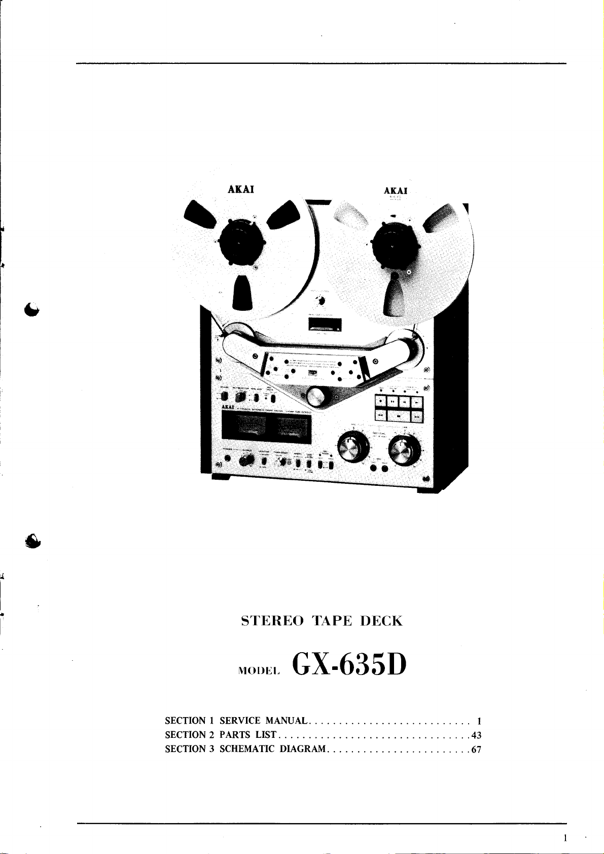
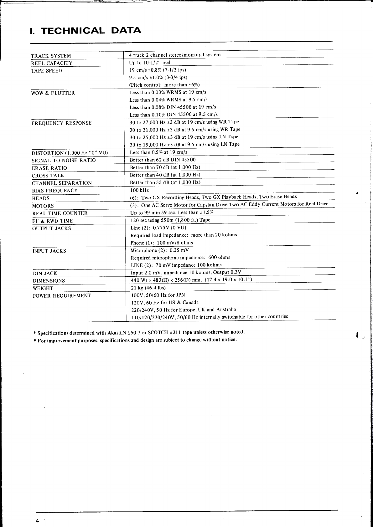
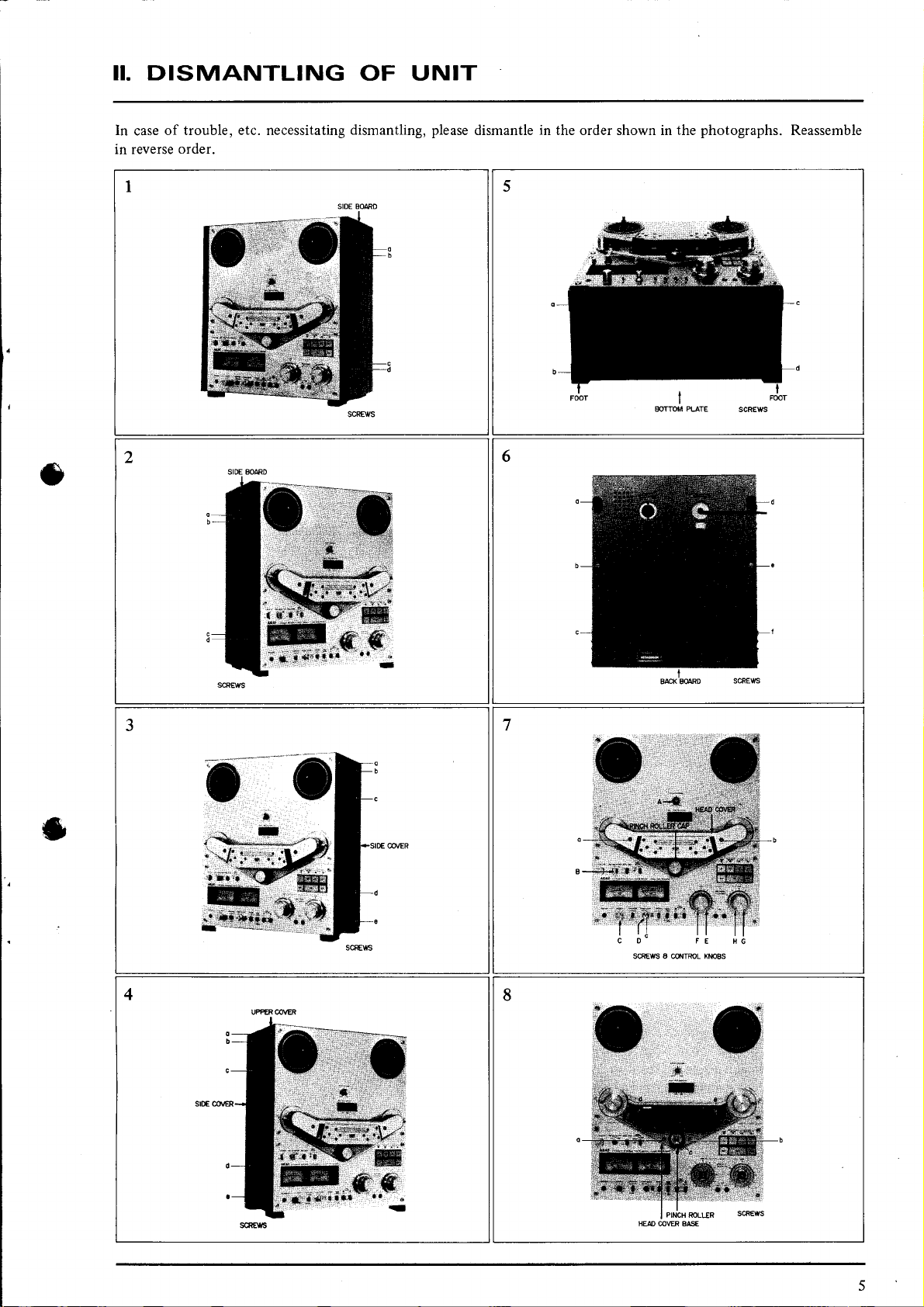
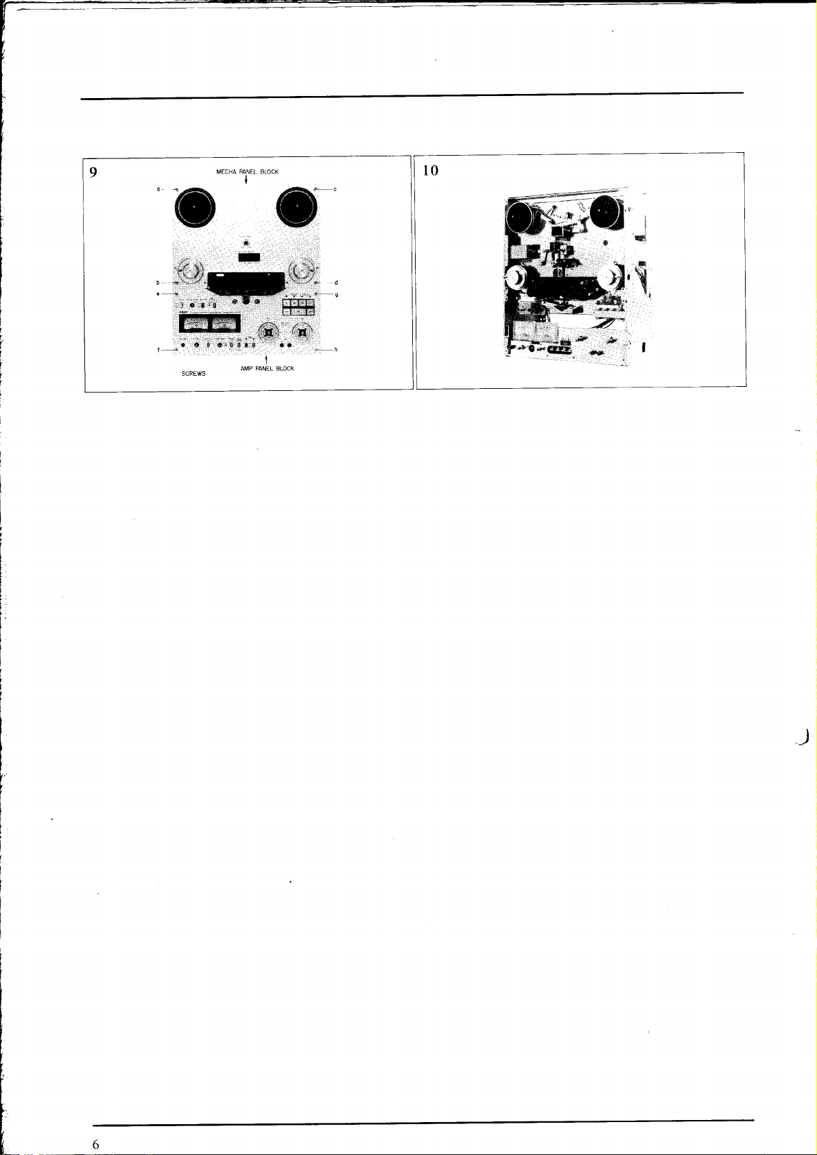
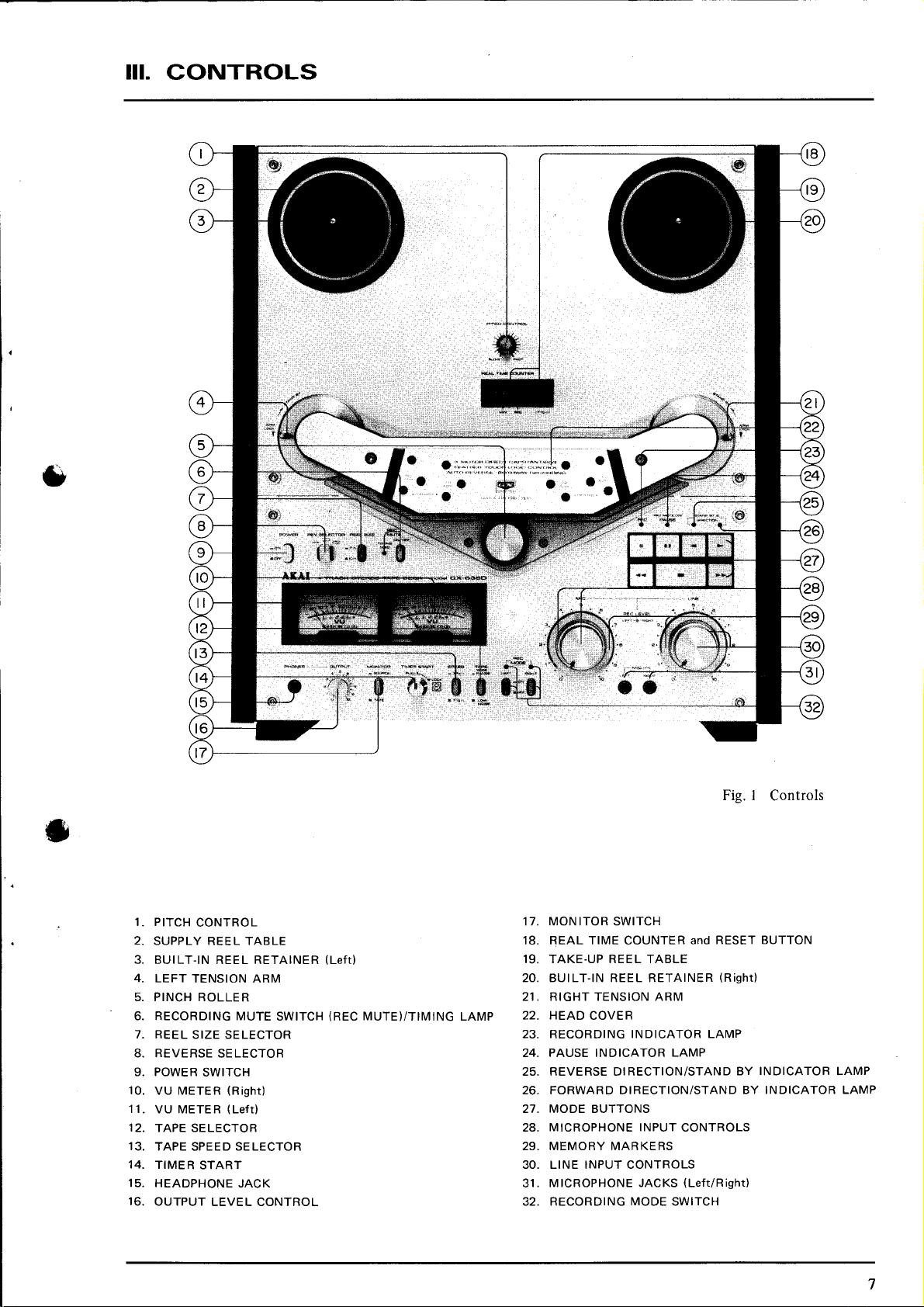
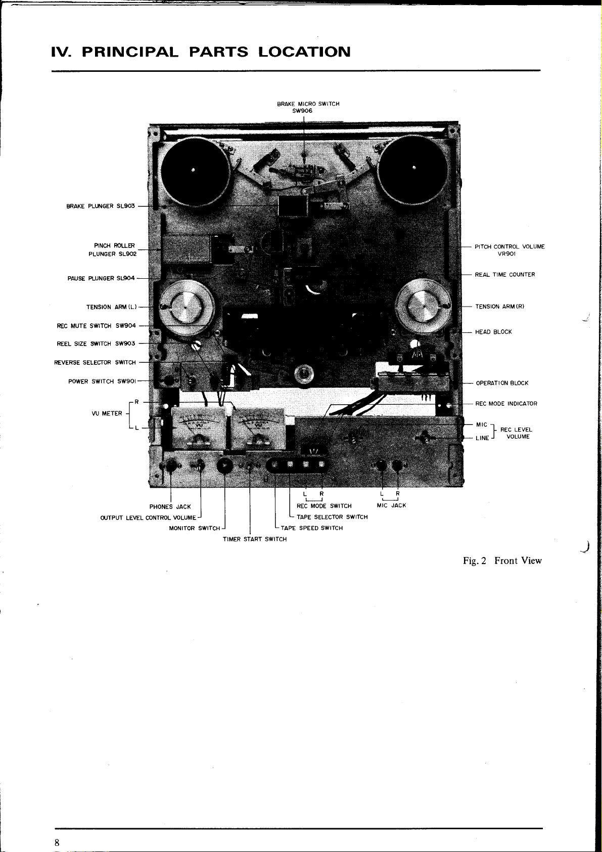
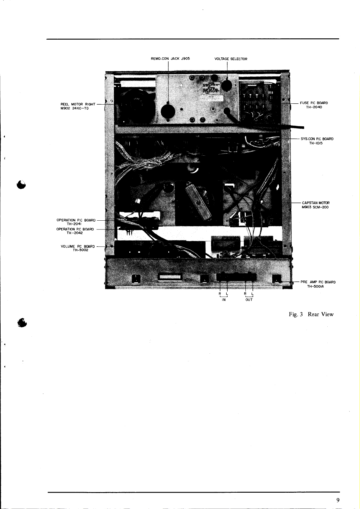
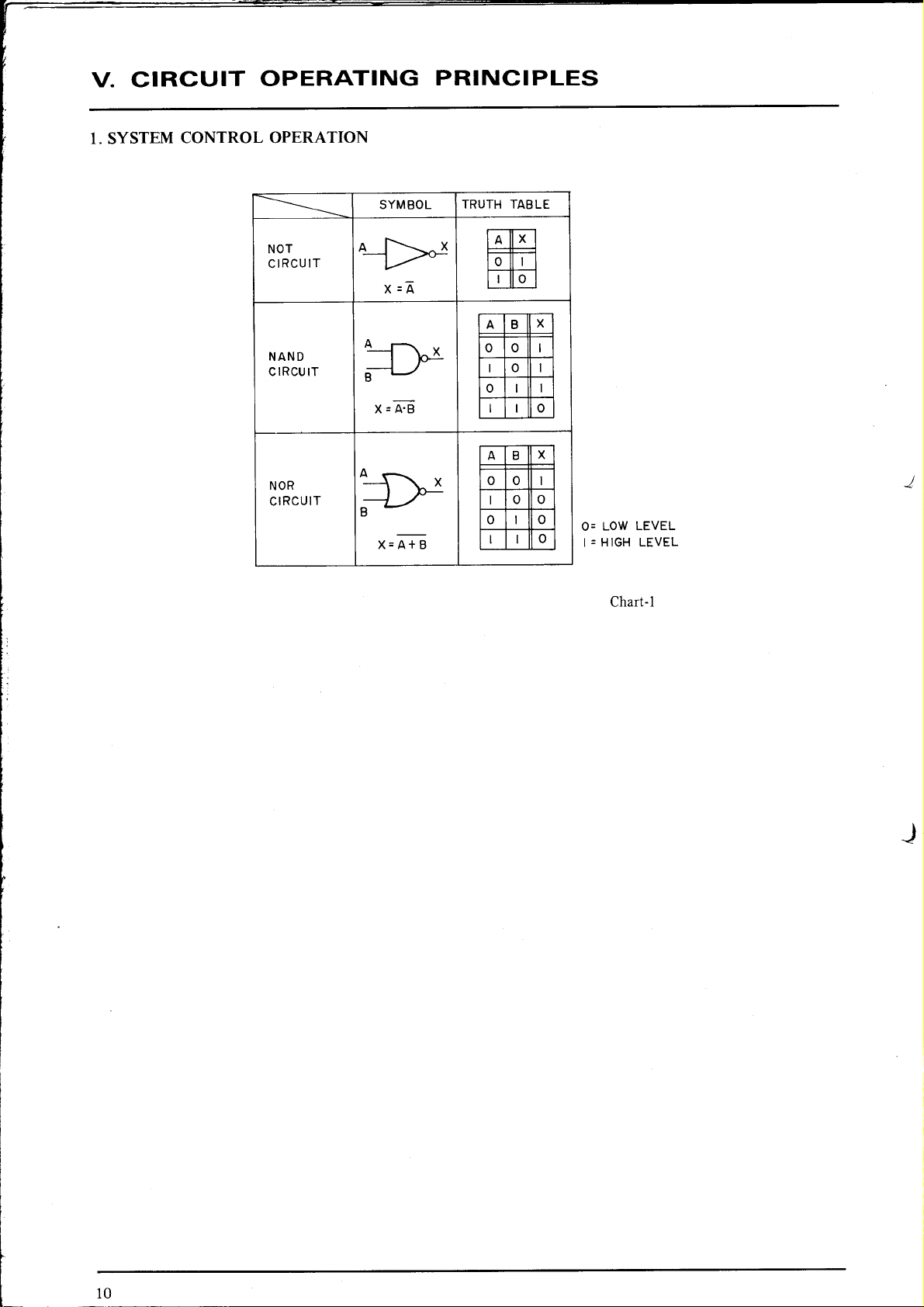
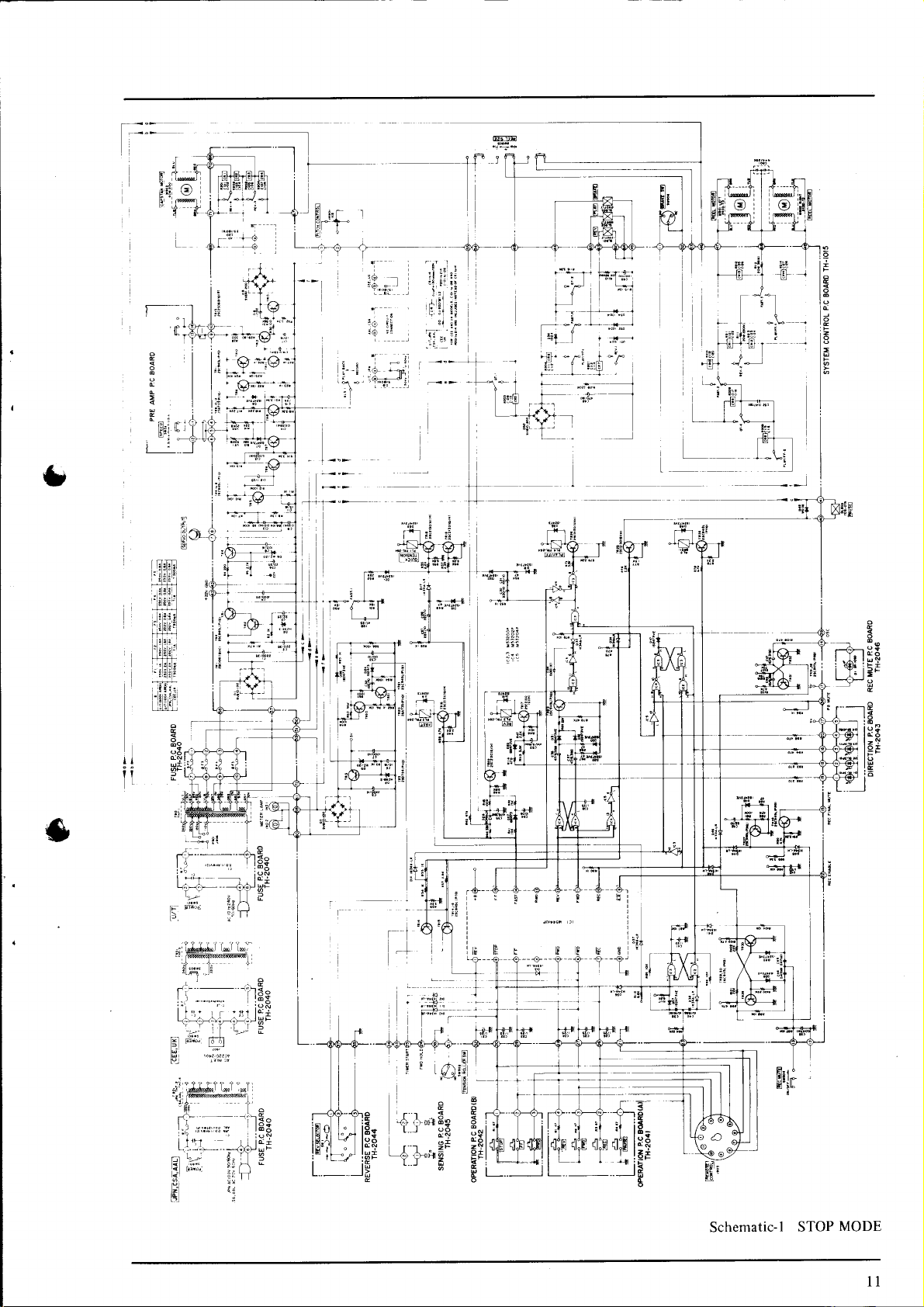
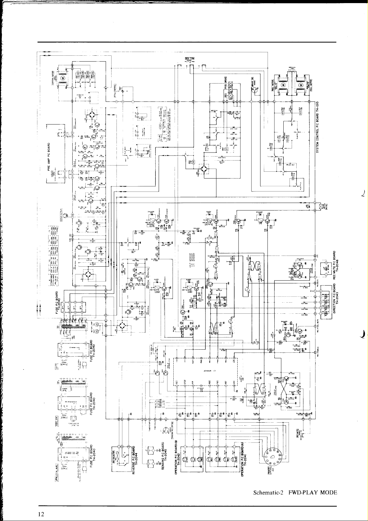
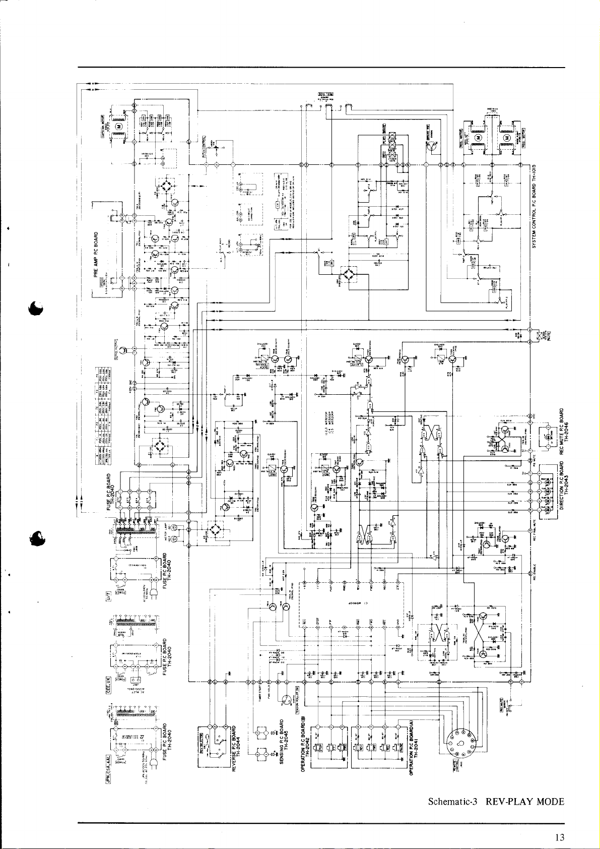
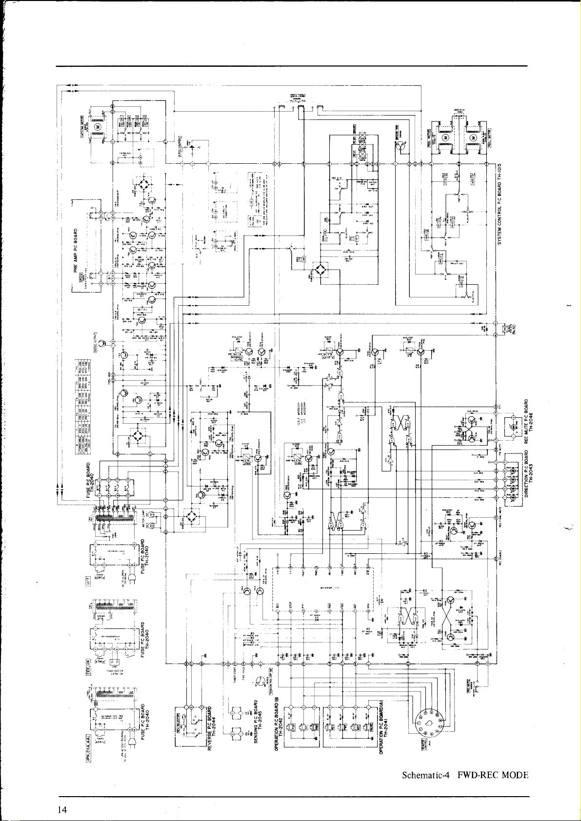
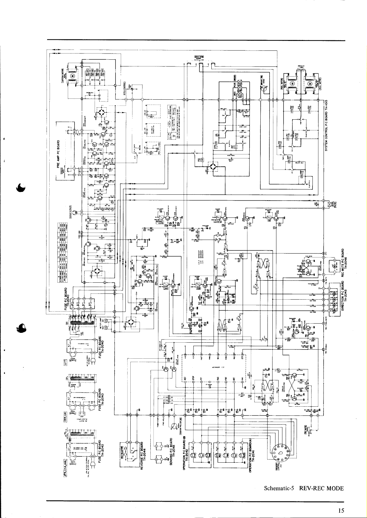
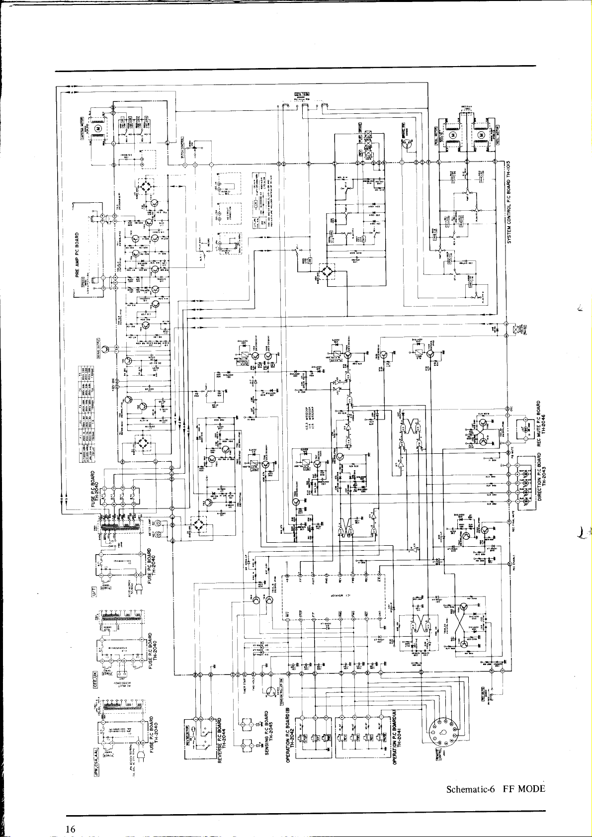
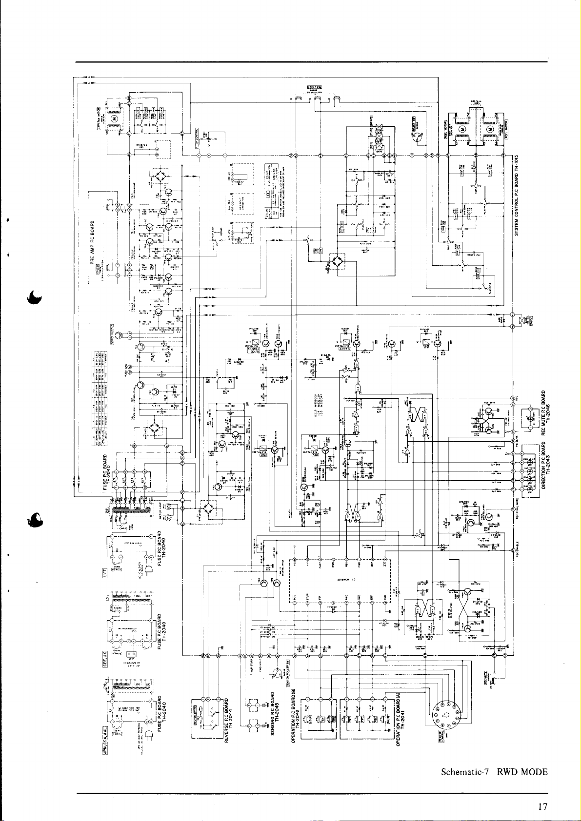
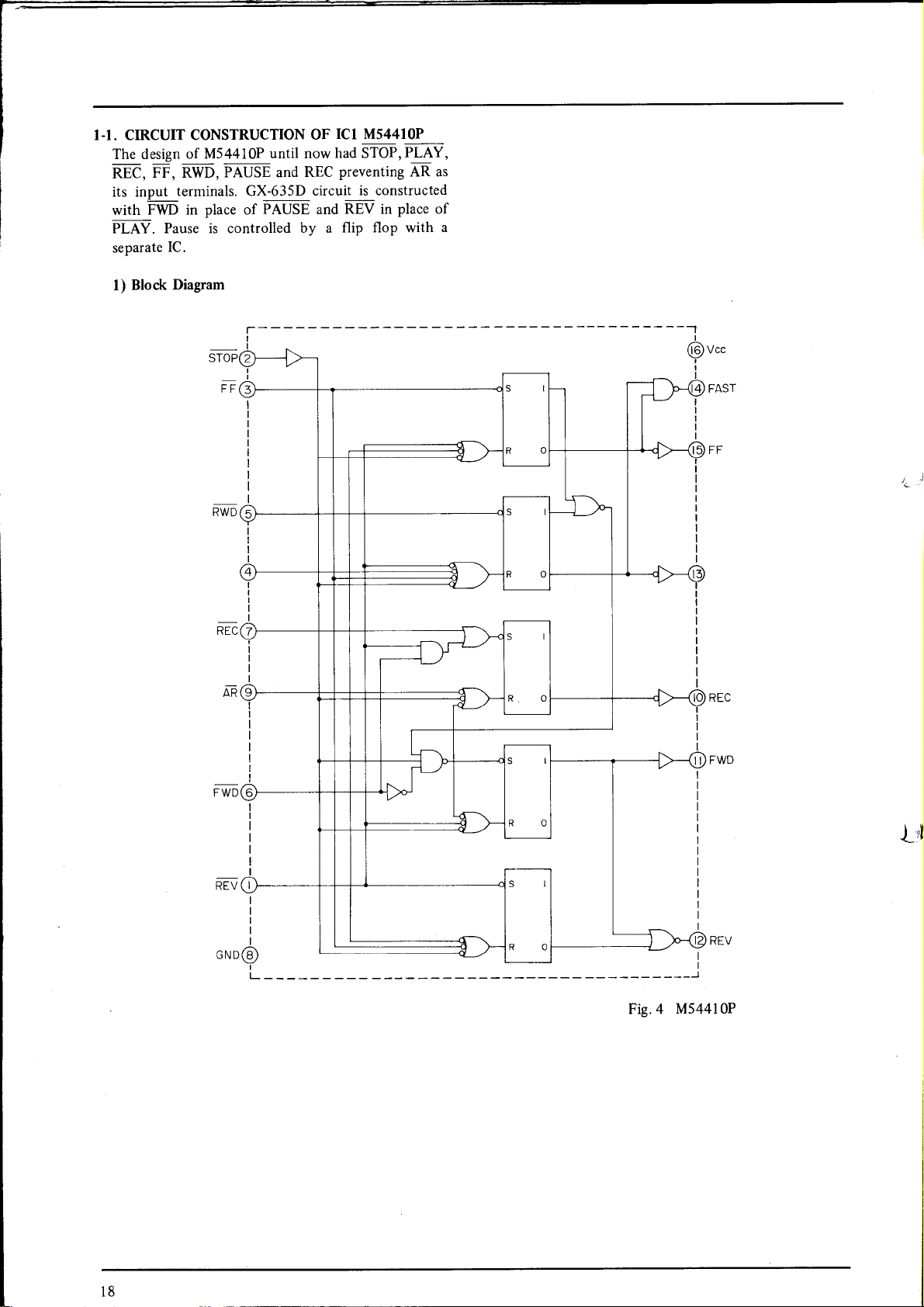
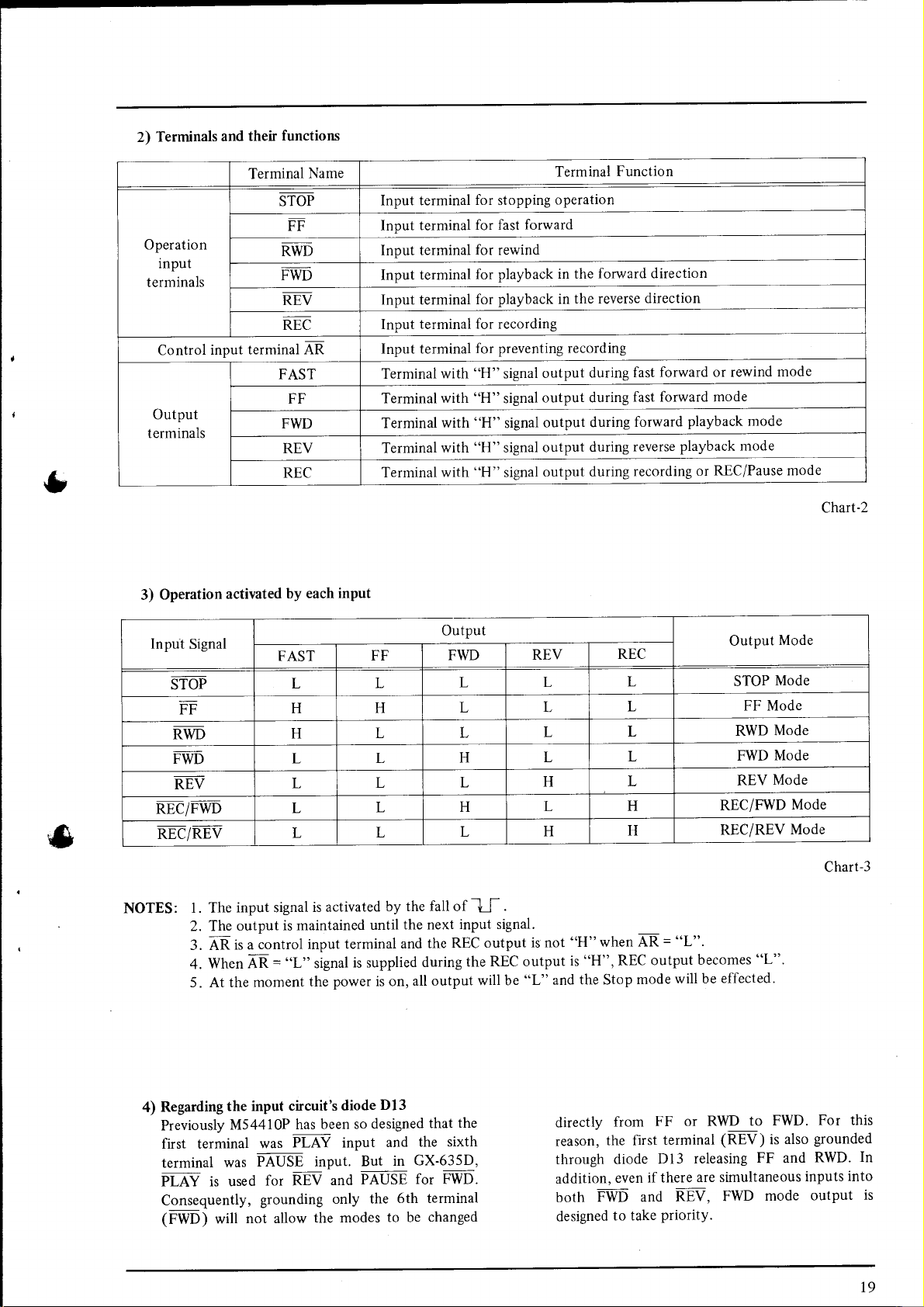
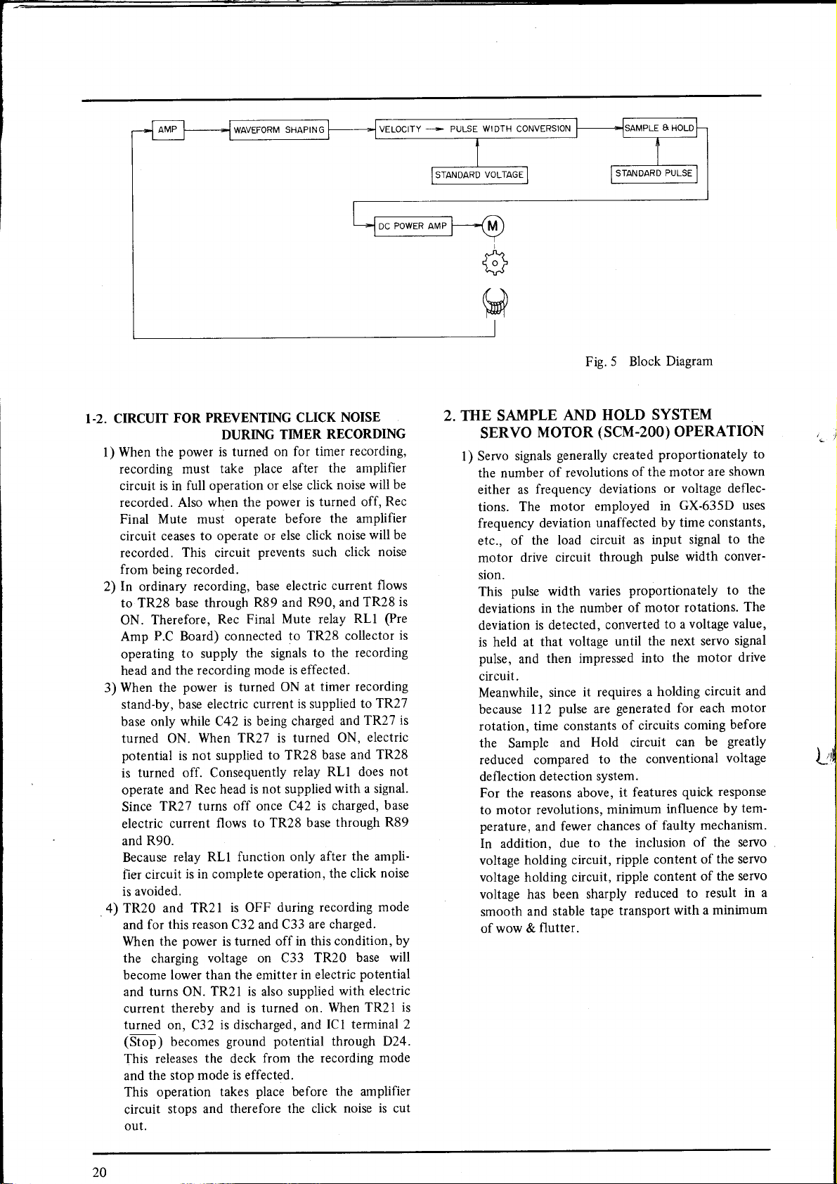
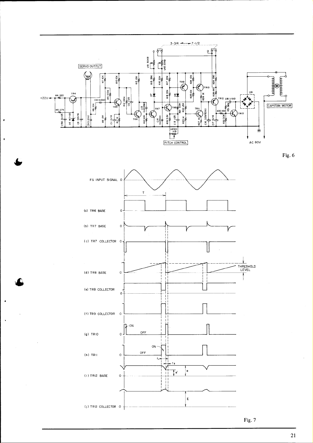


 Loading...