

Page 1
MANUAL
1 Stereo module
69113789
RF-IF module )
5829 02 58
CT 2570 UK
Ident-Nr. 5436 03 00
CT 2870 UK
Ident-Nr. 5436 03 10
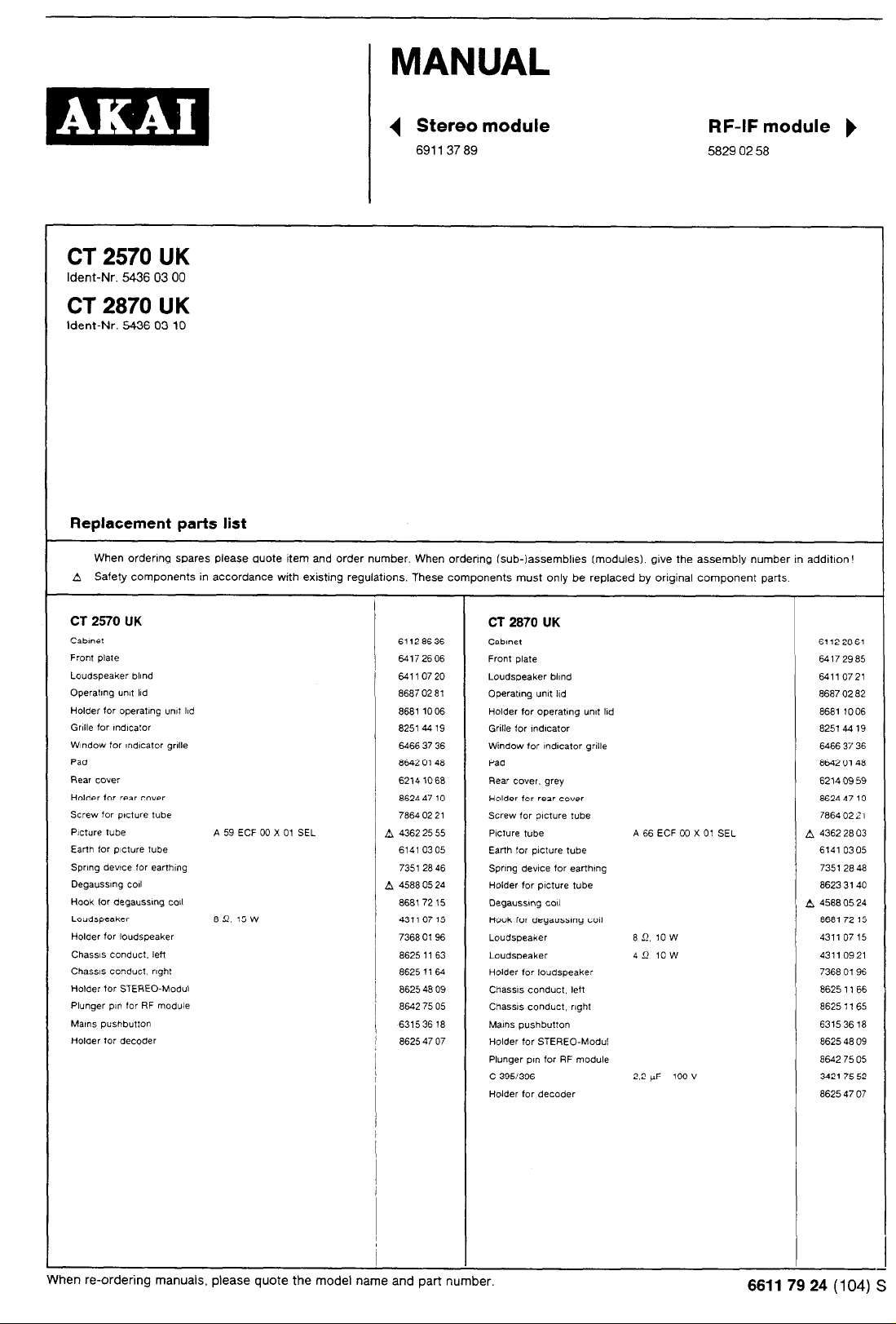
Replacement parts list
When ordenng spares please quote item and order number. When ordenng (sub-)assembks (modules), gwe the assembly number in addition!
A Safety components in accordance with existing regulations. These components must only be replaced by original component parts
CT 2570 UK CT 2870 UK
Cab,net 61128636 Cablnet 61122861
Front plate 64172606 Front
Loudspeaker blind 64110720 Loudspeaker blind 64110721
Operatlnq ““0 lid
Holder for operatmq un,t Ikd a681 10 06 Holder for umt I!d operatmq 8681 1006
Grille for mdlcator a251 44 19 Grille for lndwxtor a251 44 19
WIndow for lndlcator qrllle 6466 37 36 Window for lndlcator grille 6466 37 36
Pad 8642 0148 Pad a642 0148
Rear couer
Holder for rear cover 8624 47 10 Holder for rear cover 8624 47 10
Screw for pcture tube
Picture tube A 59 ECF 00 X 01 SEL A 43622555 Plcture tube A 66 ECF 00 X 01 SEL A 43622803
Earth for plcture tube 6141 0305 Earth for tube
Sprlnq devtce for earfh,“q 735128 46 Spnnq dewce for earthmq 7351 28 48
Deqausslnq co11 A 45880524 Holder for picture tube 8623 3140
Hook for deqausstnq coil 868172 15 Deqausmg cal A 4588 05 24
Loudspeaker
Holder for loudspeaker 73680196 Loudspeaker an. IOW 431107 15
Chaws conduct, left 8625 11 63 Loudspeaker 4 S!. 10 w 43110921
Chassis co”duct. rlqht 86251164 Holder for loudspeaker 7368 0196
Holder for STEREO-Modul 8625 48 09 Chassis conduct. left 8625 11 66
Plunger pi” for RF module a642 75 05 Chassis conduct, right 8625 1165
Matns pushbutton 631536 la Mains pushbutton 631536 18
Holder for decoder 8625 47 07 Holder for STEREO-Modul 86254809
89.15~
86870281
6214 $068 Rear ccwer. qrey
78640221
43110715
plate
Operattnq U”,t Ild a687 02 a2
Screw for picture tube
pxture
Hook for deqaussmq toll
Plunger PI” for RF module a642 75 05
c 3951396 2.2 UF 100 V 342175 52
Holder for decoder 8625 47 07
64172985
62140959
18640221
6141 0305
86817215
When re-ordering manuals, please quote the model name and part number.
66117924(104)S
Page 2
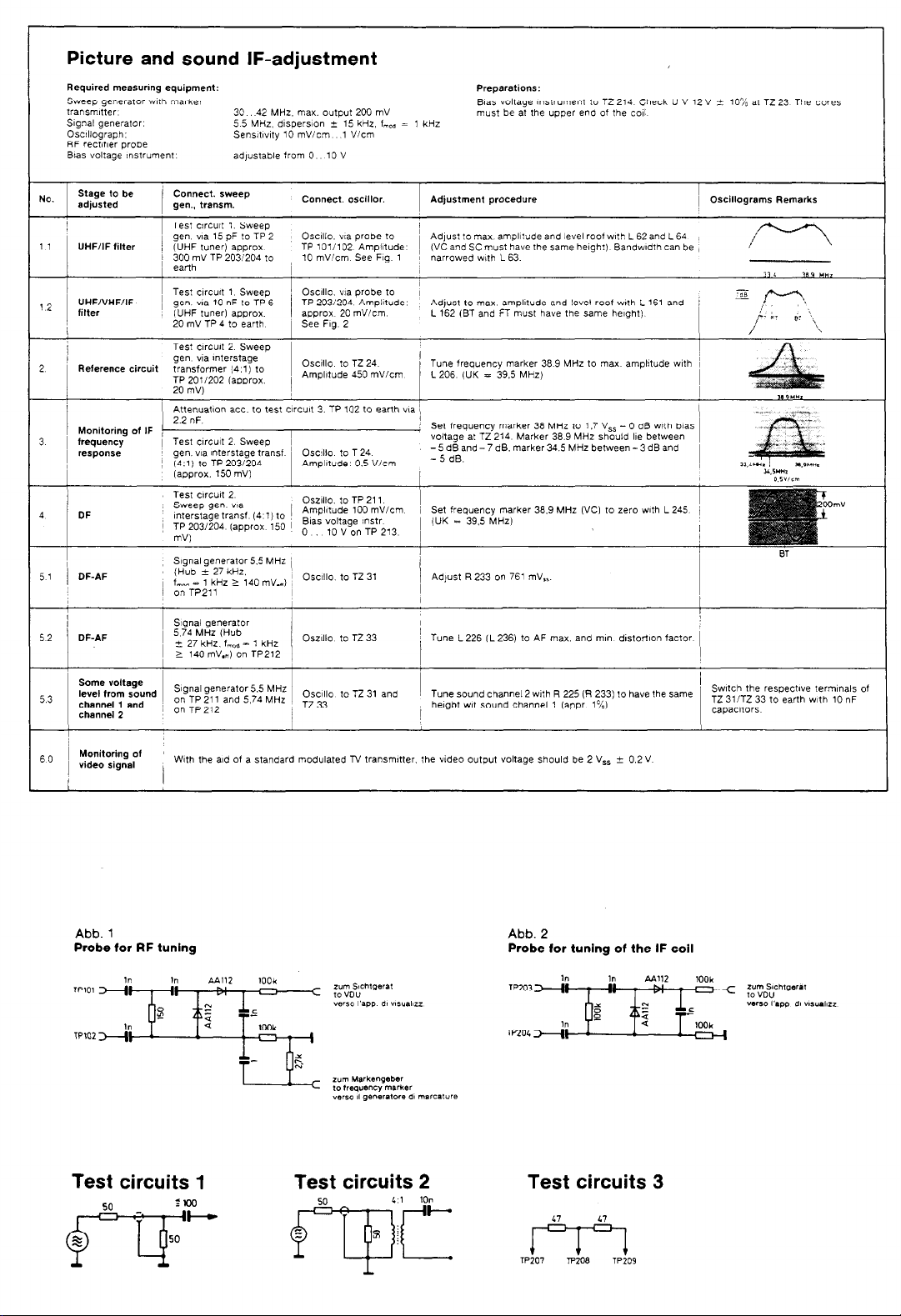
Picture and sound IF-adjustment
Required measurmg equipment:
sweep generator Wlfh marker
tr=“Smltte,
SIgnal generator.
Oscillograph:
RF rectifier probe
B!as voltage ,nstrument
Stage to be
NO.
adjusted
1 1
UHF/IF filter
Test arcu~t 1. Sweep
, gen. “,a 15 pF to TP 2
/ (UHF tuner) approx
I 300 mV TP 203/204 to
30 42 MHz. max. output 200 mV
5 5 MHz. dispersion k 15 kHz, f,,. = 1 kHz
Sens~t~v~ry 10 mV/cm 1 V/cm
adjustable from 0 10 V
Connect. oscillor.
Osc~llo. “,a probe to
TP 101/102 Ampiltude (VC and SC must have the same helghf) Bandwtdth can be
10 mV/cm See Fig 1
Preparations:
!&as voltage instrument to TZ 214 Check U V 12 V i 10% at TZ 23 The cores
must be at the upper end of the co11
Adjustment procedure ~ Oscillograms Remarks
I
Adjust to max. amplitude and level roof with L 62and L 64
narrowed wth L 63.
I
UHF/VHF/IF-
12
filter
2 Reference circuit
Monitoring of IF x
3 1 frequency
response gen. via Interstage transf Osc~llo to T 24
52 DF-AF
Some voltage
level from sound
5.3
channel 1 and
channel 2
1 Monitoring of
60
video signal
1 Test c,rcu,t 1 Sweep ’ Osc~llo. “,a probe to
en. “aa 10 nF to TP 6 TP 2031204 Amplitude Adjust to max amplitude and level roof wth L 161 and /
I g
(UHF tuner) approx. approx 20 mVicm L 162 (BT and FT must have the same height)
20 mV TP 4 to earth
Test c,rcu8t 2 Sweep 1
gen "Ia mterstage
transformer (4.1) to
TP 2011202 (approx.
20 mVI
Attenuatnn xc. tq test ClrCult 3. TP 102 to earth wa ’ (
) 2.2 “F’
/ Test circuit 2 Sweep ~
~ (4.1) to TP 2031204
(approx. 150 mV1
SIgnal generator
( ~zx;,;k~; osz”‘o to Tz33
I
Signal generator5.5 MHZ
on TP 211 and 5.74 MHz
~ on TP2,2
With the ald of a standard modulated N transmitter. the video output voltage should be 2 V,, + 0.2 V
1 See Fig 2
I
Osc~llo to TZ 24 Tune frequency marker 38.9 MHz to max amplttude with ~
Amplitude 450 mV/cm L206 (UK = 39.5 MHz)
Set frequency marker 36 MHz to 1.7 V,, - 0 d0 with bias
voltage at TZ 214 Marker 36.9 MHz should Ile between
- 5 dB and - 7 dB. marker 34.5 MHz between - 3 dB and
Amplitude 0.5 V/cm
Osc~llo to TZ 31 Adjust R 233 on 761 mV,,.
Osc~llc to TZ 31 and
Ti! 33
- 5 dB.
I
’ / Tune L 226 CL2361 to AF max. and ml” dlstortlon factor 1
Tune sound channel 2 wth R 225 (R 233) to have the same
haght wt sound channel 1 (appr 1%).
A “,
I
I
Swtch the respectwe term,“& of
TZ 3liTZ 33 to earth v&h 10 nF
capacitors
389YHI
-“.- ~.,-“m,
Y,5”*2
Abb. 1
Probe for RF tuning
Test circuits 1
Abb. 2
Probe for tuning of the IF coil
Test circuits 3
Page 3
_. _ _ _ _
MS, PARALLELTON 5T”FE
(51 PARALLEL SOUND STAGE
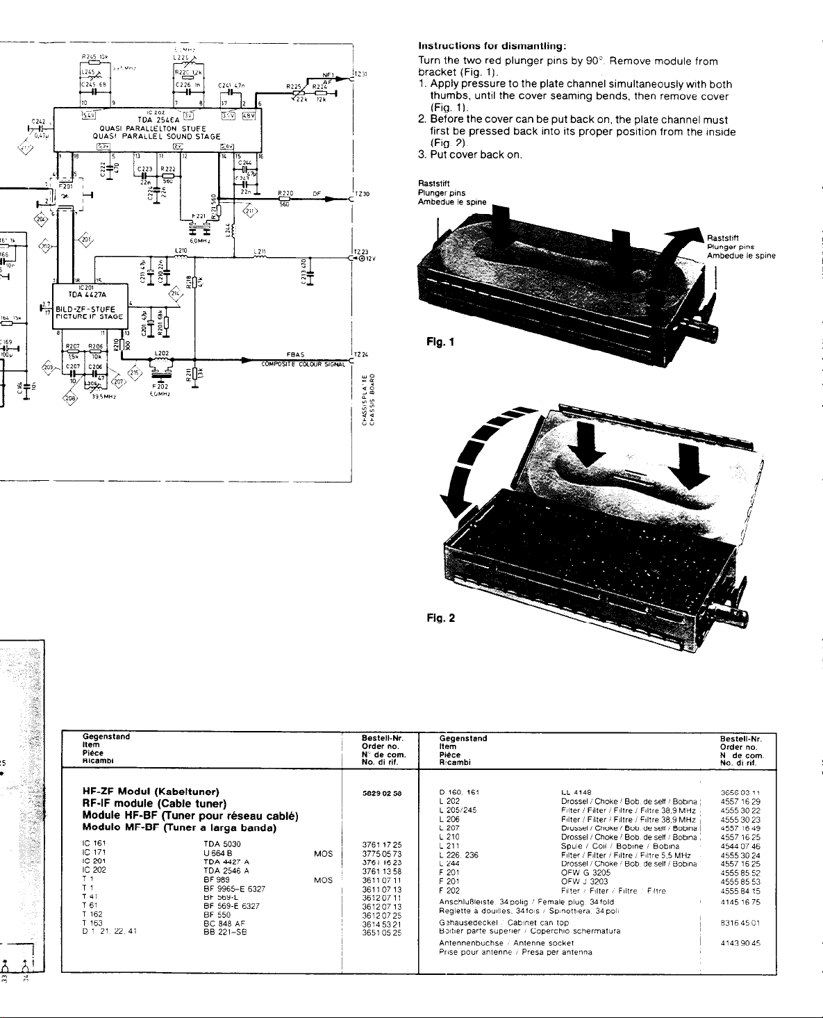
Instructions for dismantling:
Turn the two red plunger pins by 90” Remove module from
bracket (Fig. 1).
1. Apply pressure to the plate channel simultaneously with both
thumbs, until the cover seaming bends, then remove cover
(Fig. 1).
2. Before the cover can be put back on, the plate channel must
I
first be pressed back into its proper position from the InsIde
(Fig. 2).
3. Put cover back on.
Raststift
Plunaer p,ns
Ambedue le spme
Gegenstand
Item
Pike
Ricambi
HF-ZF Modul (Kabeltuner)
RF-IF module (Cable tuner)
Module HF-BF (Tuner rhseau cable)
pour
Modulo MF-BF (Tuner a larga banda)
IC 161 TDA 5030
IC 171
IC 201 TDA 4427 A
IC 202 TDA 2546 A
Tl BF 989
T, BF 996>E 6327
T 41 BF 569-L
T 61 BF 569-E 6327
T 162 BF 550
T 163 BC 848 AF
D 1 21 22 41 EB 221-S?
U664B
Bestell-Nr.
1 Order no.
N‘ de corn.
No. di rif.
5829 02 58
MOS 3775 05 73
MOS 36110711 F 201 J OFW 3203
3761 1725 L 211
3761 1623 L 244 I
3761 1358 F 201 OFW G 3205
361107 13 F 202 Filter ’ F,lter I Fiitre
36120711
361207 13
3612 07 25
36145321
3651 0525
I
~
Gegenstand
Item
Pi&x
R’cambi
D 160 161 LL 4148
L 202 Drossel i Choke 1 Bob
L 2051245 F~ifer / Filter / Flltre /
L 206
L 207 Drossel i Choke I Bob de se” i Bob,na I
L 210 DrosselI Choke 1 Bob
L 226 236 1 1 Filter Fflter Flltre i Fllfre 5.5 MHz 4555 30 24
Anschlufllelste 34pollg Female piug 34fold
Reglette a doullles. 34fo1s I Sp~noft~era 34~011
G?hausedeckel Cabinet can top
B3her parte super~er I Coperchlo schermatura
Antennenbuchse Antenne socket I 41439045
PIIse pour antenne I press per antenna
Filter ! Filter / Flltre i F,ltre 38.9 MHz ~
Spule i Co11 i Bobme i Bob,na
Drossel Choke Bob f de sell Bobina / 4557 16 25
’
Bestell-Nr.
Order no.
N de corn.
No. d, rd.
de sell 1 Boblna ~ 4557 16 29
Filtre 38.9 MHZ 45553022
de setl i Boblna ~ 4557 16 25
F~ltre
36560311
45553023
4557 1649
4544 07 46
45558552
4555 85 53
4555 84 15
41451675
i 83164501
Page 4
L
I---+
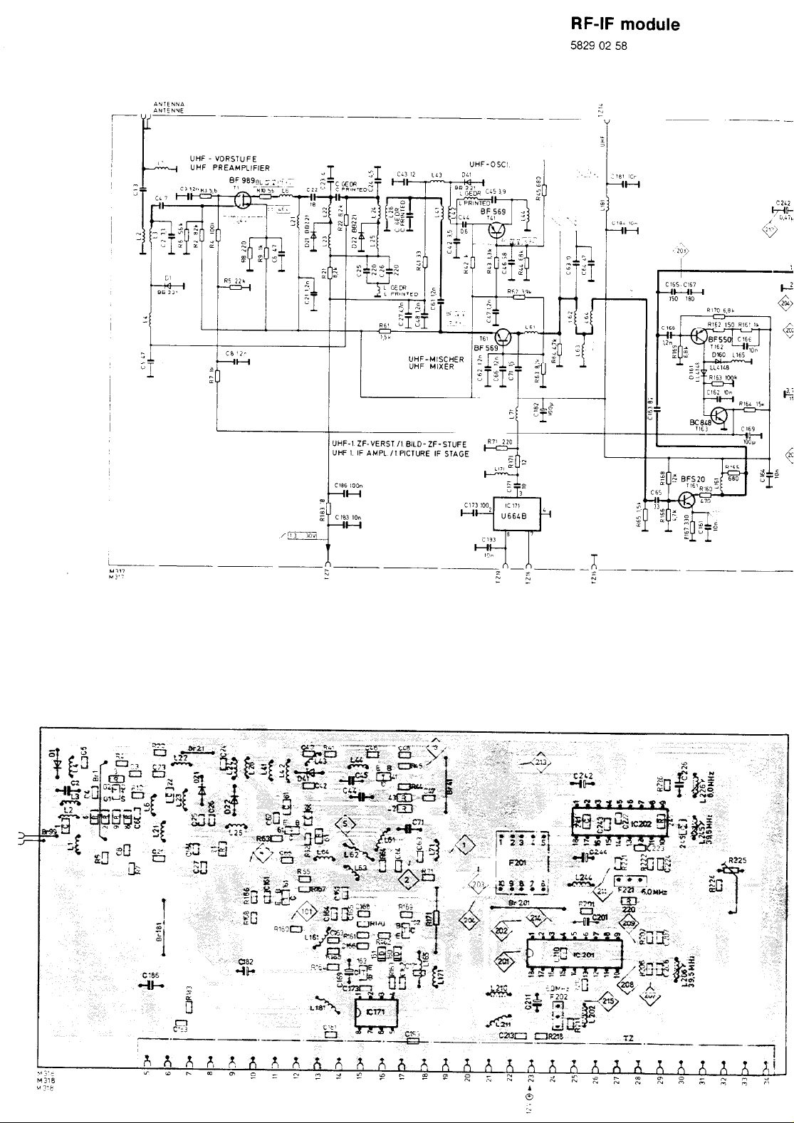
UHF “DRSTUFE
UHF PREAMPLlFiER
RF-IF module
5829 02 58
n-n--.-- -
E
K
h
-- _--. ___
2
”
Page 5

Stereo module/C
6911 37 69
II I
Page 6

After changing or repaiflng a module,
Pllo, *Igtul l Ilgnment
check
the oscillator frequency and adjust if necessary.
F.,.-
;\
6
-----
1
Page 7

I
I
18
AMPLITUDENSIEE, HOR U “ERT OSZltLATOR
SYNC SEPARATOR HOR A “ERT OSClttATOR
TDA 8371
CIRCUIT0 ALiMENlAZtONE RRE
Please note:
When exchanging T 701. IC 701 must likewise be
exchanged.
e
----P----P.-~-.
NETZVERWNDEN / MAINS CONNECTED
COLLEGATO ALLA RETE
NETZGETRENNT i
Page 8

Chassis Compact D/2 FST
P1
69’
swttc
POS
*WI
401
SC
i
-as
605
11
a.*
101
5861 75 22
K 3101
TEAZOlLA ,
VIDEO-SCHALTER
3
VIDEO-SWITCH
1 I”
.Q 12”
r
A-
B-
VeR Amplotude
1
9
a
0
CD
e
Vert. ampl,t”de
Amolltude vert
Ambezza verwale
Her Amplitude
Her amplitude
Amplatude her
Ampiezza onzzontale
Vert EMage
vert picture slvft
“BR de I image
Pos verncaie lmmaglne
HOT 811dlage
Her picture shift
Pas her de ,‘,mage
Pos OrlzzOntale lmmaglne
Vert Frequenz
vert frequency
Frequence vert
Frequenza verwale
HOT Frequenz
Her frequency
Frequence her
Frequenza or,zzontale
Sandcastle
A
- NF-Sagn
- ~2;L,”
-~ vert Imp
AF sign
BF sag”.
Camp colour stgn
CLSS i CLSS
With the equpment
-i
0
0
.-
.-
865
0
.--
~-
--
CompacI- Chassis D/Z llO”- FST
5661 75 22
Page 9

PAL Decoder
GIOC
Bell-j
6911 30 28
R410 2:
@ :v
8 1:;
Q ii
PAL - DECODER
With the equipment switched to stand-by, the voltages of the switched-mode power supply and the horizontal output stage are below nomlnal value.
Vert Amplitude
‘Jerl ampl,tude
Amplcude ven
Ampiezza
vmcale
Hor Amplitude
HOr ampl,tude
Amplntude her
Amplezza cmzzontale
Ven Frequenz
ven. frequencv
Frequence v&t
Fwquenza verwale
Her Frequenz
Her. frequency
Frequence tvx
Frequenza orizzontale
Sandcastle
NF-Stgn
AF s,gn
BF sign
BF sign
FBAS-s,gn.
Camp coio~r sign
CLSS i ass
kl Imp
Her mp
lmportanl
Follow,~g exe
c r t board h;
Thedexder
Standard PAI
mum ad br,;
-
FHT-I
Sub-8
Oscil
Oscil
PALPAL I
Demo
Demo
Filtre
Fillrc
(D.X
(Deem
SEC1
(Dee’
(oec
SEC1
(Dee
(DW
-
Page 10

CRT. base board
_--~-.-.-.-.-.--.-.-.-.-.- .-.---.-. --.-.-,
IVIDEO ENDSTUFEN UND EILDR6HRENANSCHLUSSPLAnE
wlE0 oum STnGEs AN0 PICTURE TUBE CoNNEcTlffi BOARCJ
,STADlO FINALEvlDEO E PlpsTRA COLLEGI\MENTO DEL CINESCOPIO
Important:
Followg exchange or repair of the colour decoder. ensure that the adait~onal earth connection
c r t boara has been re-establlshea before swltchxnq on the set
The de:.oder waveforms are taken under following conalt,ons
Standard PAL that IS. SECAM coiour bar pattern. contrast at maximum aid brightness and colour saturation at nominal value
PAL SECAM Decoder 6911 30 3016911 30 29 “9 - 12 V kontr.,cont
FHT-Oszillator
Sub-carrier oscillator
Oscillateur FHT
Oscillatore FHT
PAL-Dematrix
PAL dematrix
Dematrice PAL
Dematrice PAL
Glockenlilter
Bell-jar filter
Filtre de c&he
Filtro a campana
[Decoder 6911 30 30)
[Decoder 6911 30 29)
SECAM-Discrim. (R-Y)
[Decoder 6911 30 30)
pecoder 6911 30 29)
SECAM-Discrim. (B-Y) /
[Decoder 6911 30 30) 1 L 835
(Decoder 6911 30 29)
c 875
LB84
~ R 883 verschwndenae Jalouse I”, Feld + V i ” /
I
j LB10
1
/
i j
L 830
annaherna stehende Farblnformatlon
near stationary colo”rs
sur I’mformatlon de couleur presque stable
su Inf di coiore appross,mafa
verschwlnaende &louse urn Feld .G-Y - 0”
minimum Hanover bars I,, “G-Y - 0’
SLIT ~&USE dlsparalssante dans
I” mod0 da ottenere una spar,z,one delle str~sce nei campo <<G-Y = O>,
m~“r”“m Hanover bars I” + V i”
sur jalousie alsparaxsanle dans le champ + V i u
I” modo da ottenere una
DaR die Amplitude belder Zellen be1 schwarz/welR und wahrena des Frequent-Nulldurchganges
glelch
slnd
I That the amplitude 01 both lines IS the same with blacklwhw and during zero frequency passage
De SOrte q”e les amplitudes des deux lignes Solent identtques. en “nr et blanc et durant le passage i anderschrelben.
par zero de ia frequence
Che I’ampiltudine dl ambedue ie rlghe nel case di blanco e nero e durante 11 passagglo aella
frequenza per IO zero 518 uguale
Schwarz- u WelOpegel = deckungsglelch zu Austastpegel
10 where the black level and the white level coincide on the blank,ng leve,
i I’egal~satlon du wea” “01r et nfveau blanc qu’ll sort s~tue au niveau de suppression
I” mado the II l~vello del nero e quello de1 blanco siano congruentf sul l~vello d, tancella~~one
PAL Decoder 6911 30 26/6911 30 26
ie
Champ ‘<G-Y = 0,.
spmmne
delle str~sc~e nel campo + v t u
\
FuBK-Testblld
! Test picture
) mre
1 mmag~ne di test
~
OSCL - a10
0
Zwe~ Zellen “berein- rmre de couleur
Adjust to converge two
consecuf~ve lines
Ecnre 2 ilgnes i’une sur
I’autre
Scrwere 2 rIghe ““a
sovrapposta all’altra
SECAM-Farbb
Colour bar sfgn
bane df coiore
Page 11

r
Indicator board
--
0
51‘01
n
IFB 473 UK
58831490
LTO 6LtO G
Awl
Program board
Indicator board, IFB 473/483
Base board
Hint for
antenna
Because of the ever mcreas~ng number of lnterferance sources and their negatwe etfe
only shlelded (75 ohm) antenna cables and antenna plugs (DIN 45325) should be use,
possible Interference suppress!on Unshielded antenna cables. balanced-to-unbalam
and antenna plugs often prove lnsufftclent for In!erference-tree reception.
Repalr tips
1. With dlsconnectedswltchlng stage T 701 (base open), the power supply 15 capable 01
As no output voltages are generated I” this co”d,t,o”. the IC 601 IS wlthout SUPPly “(
m other words. the power supply is not synchromsed.
Rectangular pulses w,th approx 14.6 kHz are measureable at Pin 14 (IC 7011.
However. the IC operates I” so-called Interrupt mode, 1.e the pulse voltage at Pin ’
200 ms.
N. B. If the swtchmg stage IS dlsconnected. the electroiytlc capacitor C. 656 mi
re-con”ectnon (soldering)
2 With disconnected hotl?ontal cutput stage ,e.g termma, 4 Tr 501 open, and a repla
of D 733 (60 watt lamp). the power supply delivers approx 110 V (Compact D) ca.
3 If the T701 (ON 4046) falls repeatedly. the followng components should be replac
even If these are OK according to the ohmmeter, and C 704
4. For servnng the set under operatong condltons when the election~c fuse has a<
~CIOSS C 700 (C 713) If the eiectronlc fuse cuts out due to a momentary over1
re-started by swltchmg the mans swtch off and the” on agal”
connecttng
.
Page 12

Chassis board / CRT. base board / Color decoder board
4
FLOF decoder
6911 1159
SAA
j2LO PIA
SAA
5210 PI0
cm
SW RAM
STATIC RAM
m BUS-WANOLER
BUS-CONVERTE
IM BUS -mm
I
I
m 25 I+T ERZEUGUNG FUR
g
.
ZWISCHENZEILENABSCHAL~UNG
-
NNUNG OER VT-SIGNALE I
a VT-PROZESSOR
-PROCESSOR
Cz.0‘1
, 12
B
33
2 1
C30‘2
‘6 NAB 8‘61 28
.I
2
I3
L
n
M03
Pay attention to protective measures for MOS components!
u
Page 13

BUS-WANOLER
BUS-COlrVERTER
IM BUS * !a BUS
I
Decoder
IC 3001 TEA5114A 3766 11 53
IC 3002 SAA 5231 MOS 3779 15 38
IC 3003 SAA 5240 MOS 3779 15 40
IC 30M CXK 5864 AP 10 L MOS 3776 01 59
IC 3005 MAB 6461 P MOS 3777 51 21
IC 3006 MEA 2050 MOS 3779 11 61
IC 3007 SAA 1272 C MOS 1 3779 11 31
IC 3006 3011 HEF 4001 BP MOS ~ 37715107
IC 3009 HEF 4006 MOS 377151 a9
IC 3010 L 7805 ACV MOS 3768 17 65
T 3001 .3004.3006 BC 048 B I 36145322
3007.3009
T 3006.3011 BC a58 c 36145423
T3010 BC a47 c
69111159
36145313
I
D D 3001 3002 ZPD LL 4148 3.3 F i 36560311 36531744
L 3001 Drossel / Choke I Bobma 4557 17 62
L 3002 Drossel i Choke i Bobma 4557 16 66
L 3004.. .3oc6 Drossel / Choke I Bobma 4557 16 37
x 3001
X 3002
IC-Fassung. 14 pol!g / IC socket. 14 fold 41563075
Zoccolo del IC. 14 poli
IC-Fassung. 16 pollg I IC socket. 16 fold
Zoccolo del IC. 16 poll
IC-Fassung. la poilg 1 IC socket. 18 fold
zOcCOl0
del IC. 18 poll
IC-Fassung. 40 pollg 1 IC socket, 40 fold
ZocColo del IC. 40 poll
Kuhlblech fur IC 3001 / Heat sink for IC 3001
Aletta dl raffreddamento per IC 3001
Ouarz i Quartz / Quarzo 13.875 MHz 4421 31 07
Ouarz / Quartz / Quarzo 6 0 MHz
/
/
442131 a0
41563076
41563077
41563080
65247303
 Loading...