

Page 1

SERVICE MANUAL
Model:
CFT2716
Safety Instructions
Features & Specifications
Block Diagram
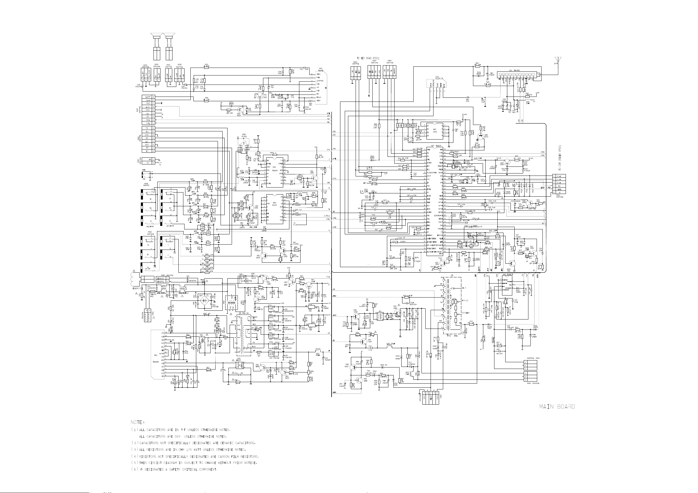
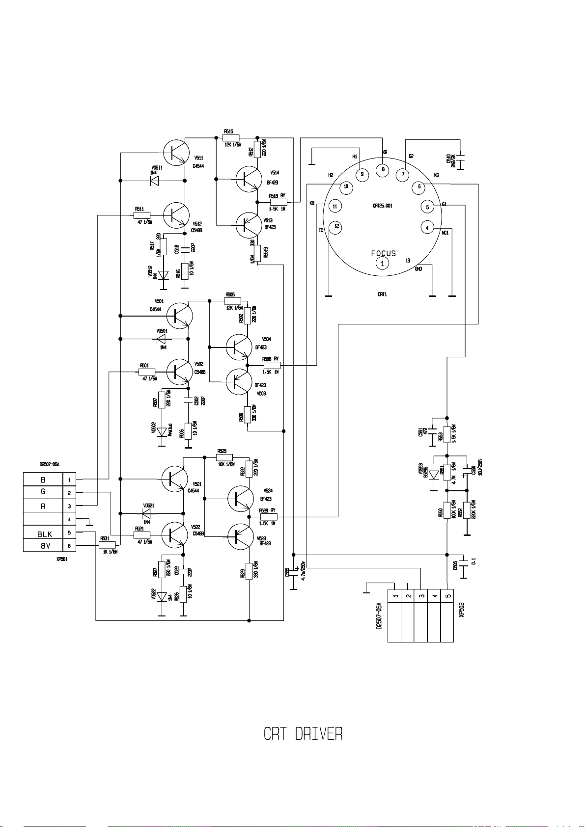
Circuit Diagram
Disassembly
Pin Descriptions
Exploded View Diagram
Spare Part List
This manual is the latest at the time of printing, and does not
include the modification which may be made after the printing,
by the constant improvement of product.
Page 2

IMPORTANT SERVICE SAFETY INFORMATION
Operating the receiver outside of its cabinet or with its back removed involves a shock hazard.
Work on these models should only be performed by those who are thoroughly familiar with precautions
necessary when working on high voltage equipment.
Exercise care when servicing this chassis with power applied. Many B plus and high voltage RF
terminals are exposed which, if carelessly contacted, can cause serious shock or result in damage to the
chassis. Maintain interconnecting ground lead connections between chassis, escutcheon, picture tube dag
and tuner when operating chassis.
These receivers have a “polarized” AC line cord. The AC plug is designed to fit into standard AC
outlets in one direction only. The wide blade connects to the “ground side” and the narrow blade
connects to the hot “side” of the AC line. This assures that the TV receiver is properly grounded to the
house wiring. If an extension cord must be used, make sure it is of the “polarized” type.
Since the chassis of this receive is connected to one side of the AC supply during operation,
service should not be attempted by anyone not familiar with the precautions necessary when working on
these types of equipment.
When it is necessary to make measurements or tests with AC power applied to the receiver chassis,
an Isolation Transformer must be used as a safety precaution and to prevent possible damage to
transistors. The Isolation Transformer should be connected between the TV line cord plug and the AC
power outlet.
Certain High voltage (HV) maybe cause X-ray radiation. Receivers should not be operated with
HV levels exceeding the specified rating for their chassis type. Higher voltage may also increase the
possibility of failure in the HV supply.
It is important to maintain specified values of all components in the horizontal and high voltage
circuits and anywhere else in the receive that could cause a rise in high voltage, or operating supply
voltages. No changes should be made the original design of the receiver.
Components shown in the shaded areas on the schematic diagram and/or identified by in the
replacement parts list should be replaced only with exact factory recommended replacement parts. The
use of unauthorized substitute parts man creats may create shock, fire, X-ray radiation, or other hazards.
To determine the presence of high voltage, use an accurate high impedance HV meter connected
between the second anode lead and he CRT dag grounding device. When servicing the High Voltage
System remove static charges from it by connecting a 10K Ohm resistor in series Wan insulated
wire(such as test probe) between the picture tube dag and 2
disconnected from AC supply).
The picture tube use in this receiver employ integral implosion protection. Replace with a tube of
the same type number for continued safety. Do not lift picture tube by the neck. Handle the picture tube
only when wearing shatterproof goggles and after discharging the high voltage completely, Keep others
without shatter proof goggles away.
Before returning the receiver to the user, perform the following safety checks:
1. Inspect all lead dress to make certain that leads are not pinched or that hardware is not lodged
between the chassis and other metal parts in the receiver.
2. Replace all protective devices such as non-metallic control knobs, insulating fishpapers, cabinet
backs, adjustment and compartment covers of shiedls, isolation resistor-capacitor networks,
mechanical insulators etc.
nd
anode lead(Have AC line cord
Page 3

3. To be sure that not shock hazard exists, a check for the presence of leakage current should be
made at each exposed metal part having a return path to the chassis (antenna, cabinet metal,
screw heads knobs and/or shafts, escutcheon, etc.) in the following manner.
Plug the AC line cord directly into a 120V, AC receptacle. (Do not use an Isolation Transformer
during these checks.) All checks must be repeated with the AC line cord plug connection reversed. (If
necessary, a nonpolarized adapter plug must be used only for the purpose of completing these checks.)
If available, measure current using an accurate leakage current tester. Any reading of 0.35mA or
more is excessive and indicates a potential shock hazard which must be corrected before returning the
receiver to owner.
If a reliable leakage current tester is not available, this allernate method of measurement should be
used. Using two clip leads, connect a 1500 Ohm, 10 watt resistor paralleled by a 0.15uF capacitor in
series with a known earth ground, such as a water pipe or conduit and the metal part to be checked. Use
a VTVM or VOM with 1000 Ohms per Volt, or higher, sensitivity to measure this AC voltage drop
across the resistor,. Any reading of 0.35 volt RMS of more is excessive and indicates potential shock
hazard which must be corrected before returning he receiver to the owner.
ALIGNMENT PROCEDURES
PLEASE READ BEFORE ATTEMPTING SERVICE
1. Use an Isolation Transformer when performing any service on this chassis.
2. Never disconnect any leads while receiver is in operation.
3. Disconnect all power before attempting an repairs.
4. Do not short any porsition of the circuit while the power is on.
5. For safety reasons, replacing any components should be according with identical replacement
parts (SEE PARTS LIST).
6. Before testing, warm up the TV for at least 30 minutes and demagnetize the CRT with an
external degaussing coil.
7. When removing a PCB or related component, after unfastening or changing a wire, be sure to
put the wire back in its original position.
8. Inferior silicon grease can damage IC’s and transistors. When replacing IC’s and transistors, use
only specified silicon grease,. Remove all old silicon when applying new silicon.
9. Before removing the anode cap, discharge eiecticity because it contains high voltage.
Page 4
FUNCTION AND SPECIFICATION
TUBE/POWER SUPPLY
TUBE TYPE PF
SIZE 27''
ASPECT RATIO
POWER SUPPLY
MAIN POWER SWITCH
TUNER
BUILT-IN FS TUNER YES
# OF CHANNEL/PROGRAM 181 CH
COLOR SYSTEM NTSC
SOUND SYSTEM M
AV NTSC 3.58/4.43 AV NTSC 3.58
PICTURE
COMB FILTER 2LINE
TINT, COLOR, BRIGHTNESS, CONTRAST AND SHARPNESS CONTROL YES
USER SELECTABLE PICTURE CONTROL(NORMAL,BRIGHT,USER,SOFT) YES
USER SELECTABLE 3-STAGE COLOR TEMPERATURE CONTROLS YES
OSD LANGUAGE
SOUND
STEREO/MONO MTS/SAP
AV STEREO YES
SURROUND YES
TONE CONTROL(BASS/TREBLE/BALANCE) YES
USER SELECTABLE SOUND CONTROL YES
SPEAKER QUANTITY 2
AUDIO OUTPUT POWER 3W×2
USER CONVENIENCE
FULL FUNCTION REMOTE CONTROL YES
CCD YES
V-CHIP YES
CHILD LOCK YES
SLEEP TIMER YES
RECALL YES
QUICK VIEW YES
CONNECTORS
CABLE/ANTENNA INPUT 1 REAR
AV INPUT 2 REAR,1SIDE
S-VIDEO INPUT 1 REAR
COMPONENT VIDEO INPUT (YCbCr) 1 REAR
AV OUTPUT 1 REAR(Audio)
HEADPHONE OUTPUT NO
4∶3
~120V,60Hz
SOFT
SWITCH
ENG,FR,SPA
Page 5
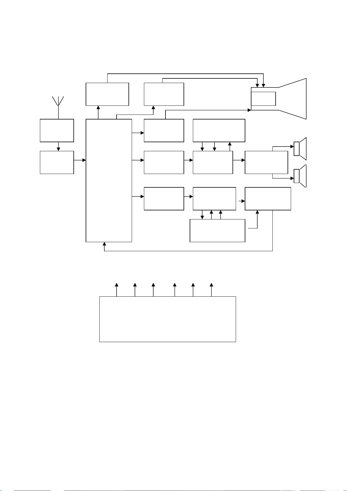
Block diagram
TUNER
SAW
V OUT
TDA8177F
NTSC M/N
UOC
TDA9378
H OUT
RGB
OUT
MTS/SAP
TDA9850
TRAP
AUDIO terminal
R/L1 R/L2 R/LO
AUDIO PRO
TDA9859
VEDIO SWITCH
TC4052
VO V1 V2 Y/C
VEDIO terminal
CRT
AUDIO POWER
TDA2616
COMB FILER
TDA9183
5V -12V 12V 18V 45V 135V
TDA16846
Page 6
Page 7
Page 8
Page 9
Page 10

Page 11

Philips Semiconductors Preliminary specification
I2C-bus controlled BTSC stereo/SAP decoder
PINNING
SYMBOL PIN DESCRIPTION
VEO 1 variable emphasis output for dbx
VEI 2 variable emphasis input for dbx
C
NR
C
M
C
DEC
AGND 6 analog ground
DGND 7 digital ground
SDA 8 serial data input/output
SCL 9 serial clock input
V
CC
COMP 11 composite input signal
V
CAP
C
P1
C
P2
C
PH
C
ADJ
CER 17 ceramic resonator
C
MO
C
SS
C
R
OUTR 21 output, right channel
C
SDE
SAP 23 SAP output
V
ref
C
L
C
ND
OUTL 27 output, left channel
MAD 28 programmable address bit
C
TW
C
TS
C
W
C
S
3 capacitor noise reduction for dbx
4 capacitor mute for SAP
5 capacitor DC-decoupling for SAP
10 supply voltage (+9 V)
12 capacitor for electronic filtering of supply
13 capacitor for pilot detector
14 capacitor for pilot detector
15 capacitor for phase detector
16 capacitor for filter adjustment
18 capacitor DC-decoupling mono
19 capacitor DC-decoupling stereo/SAP
20 adjustment capacitor, right channel
22 capacitor SAP de-emphasis
24 reference voltage 0.5 × (VCC− 1.5 V)
25 adjustment capacitor, left channel
26 noise detector capacitor
29 capacitor timing wideband for dbx
30 capacitor timing spectral for dbx
31 capacitor wideband for dbx
32 capacitor spectral for dbx
TDA9850
page
1
VEO
2
VEI
C
3
NR
C
4
M
C
5
DEC
AGND OUTL
6
7
DGND
8
SDA
SCL
V
CC
COMP
V
CAP
C
P1
C
P2
C
PH
C
ADJ
9
10
11
12
13
14
15
16
TDA9850
MHA012
Fig.2 Pin configuration.
C
32
S
C
31
W
C
30
TS
C
29
TW
MAD
28
27
C
26
ND
C
25
L
V
24
ref
SAP
23
C
22
SDE
OUTR
21
C
20
R
C
19
SS
C
18
MO
CER
17
1995 Jun 19 6
Page 12

Page 13

Page 14

Page 15

Power supply
Service Flow Chart
Check input voltage
Check voltage of C911+(12V)
Check voltage of C919+(5V)
Check voltage of C155+(3.3V)
Check RY901 turn on
Check voltage of C929+(135V)
Check voltage of C945+(48V)
Check voltage of C939+(12V)
Check voltage of C946+(-12V)
Check voltage of C994+(9V)
Check voltage of C933+(8V)
Check voltage of C930+(5V)
Page 16

CPU circuit
Vertical circuit
Check voltage of N103 pin54,pin56,pin61(3.3V)
Check waveform of N103 pin58,pin59
Check waveform of N103 pin2,pin3
Check voltage of N602 pin8 (5V)
Check waveform of N602 pin5,pin6
Check voltage of N103 pin14,pin39(8V)
Check waveform of N103 pin26
Check waveform of N103 pin21,pin22
Check voltage of N401 pin3(48V)
Check voltage of N401 pin2(12V)
Check voltage of N401 pin4(-12V)
Check waveform of N401 pin1,pin7
Check waveform of N401 pin5
Page 17

Horizontal circuit
Check voltage of N103 pin14,pin39(8V)
Check waveform of N103 pin33
Check voltage of C945+(48V)
Check waveform of V401-B
Check waveform of V401-C
Check voltage of C929+(135V)
Check waveform of V402-B
Check waveform of V402-C
Check voltage of C415+(200V)
Page 18

Video circuit
Check voltage of C109+(33V)
Check voltage of C106+(5V)
Check waveform of tuner pin4,pin5
Check waveform of tuner pin11(IF)
Check voltage of L103 and L104(8V)
Check waveform of N103 pin23,pin24
Check waveform of N103 pin38
Check waveform of N103 pin40
Check waveform of N802 pin12, pin13
Check waveform of N302 pin12, pin14, pin16
Check waveform of N103 pin42, pin43
Check waveform of N103 pin51,pin52,pin53
Check video amplify circuit
Page 19

Audio circuit
Check waveform of N103 pin28
Check waveform of N103 pin44
Check waveform of N201 pin11
Check voltage of N201 pin10(9V)
Check waveform of N201 pin8, pin9
Check waveform of N201 pin21, pin27
Check waveform of N801 pin3,pin5
Check voltage of N801 pin6(8V)
Check waveform of N801 pin16,pin17
Check waveform of N801 pin15,pin18
Check waveform of N202 pin1,pin9
Check voltage of N202 pin7
Check waveform of N202 pin4,pin6
Check waveform of speaker
Page 20

TEST EQUIPMENT
1. Standard Signal Generator (PT5820)
2. Oscilloscope
3. Digital Voltmeter
4. High Voltage Meter(40KV)
5. Demagnetizing Coil
Tip: some adjustments must be performed in the SERVICE menu. You can enter the SERVICE
menu in the following way:
1. Press the MENU button on the remote control then press the INFO button on the remote control
at least 5 times immediately.
2. Press the CH+/- buttons to select the desired mode or press 0-9 number buttons to enter the
SERVICE “X” menu directly and then press the CH+/- buttons to select the desired mode.
3. Press the VOL+/- buttons to change the settings.
IF ADJUSTMENT
1. Enter the SERVICE menu and press the number button “4” on the remote control to bring up
SERVICE 4.
2. Set the IFFS to “1”.
B+ ADJUSTMENT
TEST EQUIPMENT: DIGITAL METER
1.Operate the TV set with AC 120V.
2.Connect the digital voltmeter + lead to C929 and GND. Adjust the RP901 until the meter
reading DC135±0.5V.
GEOMETRY ADJUSMENT
1. Receive a geometry pattern.
2. Enter the SERVICE menu (SERVICE 1 for horizontal and SERVICE 2 for vertical).
3. Select a value between 0 and 63, and the changed value is stored immediately.
Horizontal:
6PAR: Horizontal Parallelogram
Set the horizontal parallelogram to change to rectangle or trapezium.
6BOW: Horizontal Bow
Set the vertical lines straight.
6HSH: Horizontal Delay (horizontal shift)
Set the horizontal centre of the picture at the centre of the tube.
Page 21

6EWW: Horizontal Width
Set the correct picture width.
6EWP: East-west parabola correction
Set the vertical lines at the sides of the screen straight.
6UCR: East-west corner-correction
Set the vertical lines in the upper corners straight.
6LCR: East-west corner-correction
Set the vertical lines in the lower corners straight.
6EWT: Trapezium correction
Set the vertical lines as vertical as possible.
Vertical:
6VSL: Vertical S-correction
Set the vertical lines as vertical as possible.
6VAM: Vertical Amplitude (picture height)
Set the correct picture height.
6SCL: Vertical Linearity
Set the height of the squares in the top and bottom of the picture so that they are equal of
the height.
6VSH: Vertical Shift
Set the vertical centre of the picture at the centre of the tube.
WHITE BALANCE ADJUSTMENT
1. Enter the TV menu and set the color mode to “NORMAL”.
2. Receive a black-white pattern with color sync signal.
3. Adjust the CONTRAST and BRIGHTNESS in such a way that the brightness value of the black
area is 5 nit and the white is 80 nit.
4. Enter the SERVICE 3 menu and adjust RED, GRN, WPR, WPG and WPB in such a way that X
and Y have the following values:
X=0.248, Y=0.299
FOCUS ADJUSTMENT
1.Set CONTRAST control to maximum position and BRIGHTNESS control to middle position.
2.Adjust FOCUS control (on the FBT) to obtain the sharpest and clearest picture on the CRT.
RF AGC
1.Receive the signal of channel 13 (VHF HIGH).
2.Set the input field strength to 60 dBμV.
3.Adjust RF AGC (TOP, in SERVICE 4) control to the point where noise is the least.
Page 22

OSD ADJUSTMENT
1.Receive the TV Signal with caption text.
2.Enter the SERVICE 2 menu..
3.Select a correct value for the items below.
6VOF: Vertical OSD position alignment
6CCV: Vertical OSD of CCD position alignment
HOF: Horizontal OSD position alignment
CCHF: Horizontal OSD of CCD position alignment
VX: Vertical Zoom (select 25)
Page 23

Page 24

Spare Part List
CFT2716 Spare Part List
Item Component Description/Country Origin Unit Qty
1. CRT, CRT Socket, D.G coil, DG thermistor, Relay
1 31002362 CRT-A68QCU770X590MGF-01-LG/U PCS 1
2 25000962 CRT SOCKET GZS10-2-AC3-14~17KV/A/M PCS 1
3 12000414 DEGAUSSING COIL KK74B-75T7D0.50-3050/U PCS 1
4 13005053 DEGAUSSING THERMISTOR T705-B60-A110-4R5M 230V-EPCOS/# PCS 1
5 34002023 RELAY G5PA-1-OMRON PCS 1
2. All ICs ( excluding the
1 19000493 *IC TDA2616-PHILIPS/# PCS 1
2 19000695 * HS817B(G)-VISHAY/# PCS 1
3 19001329 IC TDA16846-SIEMENS/# PCS 1
4 19001639 IC TDA9859-PHILIPS/# PCS 1
5 19002089 IC TDA9183-PHILLPS/# PCS 1
6 19002389 IC TDA9850-PHILIPS/# PCS 1
7 19002479 IC 24LC08B-MICROCHIP/# PCS 1
8 19002820 IC TDA8177F-ST/# PCS 1
9 19003030 *IC HEF4052BP-PHILIPS/# PCS 2
10 19003949 IC CKP1408S PHILIPS/#(TDA9378PS) KK8/KK12 PCS 1
3. All TRs ( excluding the general switching TR )
1 17000056 *TRANSISTOR 2SA1015-Y/V PCS 8
2 17000060 *TRANSISTOR 2SC1815-Y/V PCS 9
3 17000066 *TRANSISTOR 2SC2482/V PCS 1
4 17000067 *TRANSISTOR 3DA4544 PCS 3
5 17000121 TRANSISTOR 2SA1013-O-TOSHIBA/#V PCS 1
6 17000184 TRANSISTOR 2SB985-S-SANYO/#/ PCS 1
7 17000621 *TRANSISTOR D400-F/V PCS 1
8 17000651 TRANSISTOR BF423-PHILIPS/#V PCS 3
9 17000662 TRANSISTOR BF422-PHILIPS/#V PCS 3
10 17001141 *TRANSISTOR 3DD2901 PCS 1
11 17001201 TRANSISTOR BC547B-PHILIPS/# PCS 3
12 17001211 *TRANSISTOR 3DG2655/V PCS 1
13 17001231 F.E.T.SSH10N60B-FAIRCHILD/# PCS 1
14 17001341 FET IRF630B-FAIRCHILD/# PCS 1
voltage regulator )
4. Diodes ( excluding the general purpose Diode such as 1N4148etc )
1 16000172 *FAST RECOVERY DIODE RU4A-3A600V400ns PCS 3
2 16000180 *FAST RECOVERY DIODE BY299-2A800V500ns PCS 1
3 16000181 *SILICON BRIDGE RECTIFIER D3SB60-4A600V PCS 1
4 16000189 RECTIFIER DIODE IN4002-1A100V/H PCS 1
5 16000194 *FAST RECOVERY DIODE S5295G-0.5A400V0.2μs PCS 6
6 16000532 *ZENER DIODE INTEGRATED POTENTIOSTAT μPC574J-NEC/# PCS 1
Page 25

Spare Part List
7 16001041 *FAST RECOVERY DIODE TRGP10M-1A1000V250ns PCS 2
8 16001320 *FAST RECOVERY DIODETRU3YX-2A-200V0.1μs PCS 1
9 16001381 *FAST RECOVERY DIODE BYT56M-3A1000V100ns-VISHAY/# PCS 1
10 16001463 *DAMPER DIODE TE25-15-5.0A-1500V-TIANSAN PCS 1
11 16001673 * DIODE BZX79-B/C3V9-PHILIPS/#H PCS 1
12 16001675 * DIODE BZX79-B/C5V6-PHILIPS/#H PCS 1
13 16001676 * DIODE BZX79-B/C6V2-PHILIPS/#H PCS 1
14 16001680 * DIODE BZX79-B/C9V1-PHILIPS/#H PCS 1
5. Transformer ( Switching, Flyback, Line Drive etc )
1 11001453 SWITCHING TRANSF. BCK50-066/A.U PCS 1
2 30001392 FLYBACK TRANSFORMER BSC28-070/A PCS 1
3 11000244 LINE DRIVE TRANSF. BCT19F-04 PCS 1
6. Power Cord, Fuse
1 27000130 POWER SUPPLY CORD SP-12OP-D10A125V2.3MK220/U、C PCS 1
2 27000148 FUSE RT1-20-4A-L125V/# K PCS 1
7. Remote Controller , IR Receiver
1 KK-Y261N REMOTE HANDSET KK-Y261N FOR AKAI SET 1
2 21000311 IR REMOTE CONTROL RECEIVER PCS 1
8. Tuner / Saw Filter
1 32000959 TUNER TDQ-BFSNS2/2 PCS 1
2 20000762 *SAW FILTER M1967-NIANYAN PCS 1
9. Speaker
1 29000086 SPEAKER YDP58×126F-4 8Ω7W PCS 2
10. Mechanical part ( Front Mask, Back cover etc )
1 36022782 FRONT CABINET 200*KP290810/101C-121 PCS 1
2 36022784 FUNCTION PRESS BUTTON 291*KP290810/101D PCS 2
3 36022785 POWER BUTTON 292*KP290810/101D PCS 1
4 36022786 263*KP290820/101J PCS 1
5 36022875 263*KP210820/101J PCS 1
6 36024095 BACK CABINET202*KP290811/101C-116! PCS 1
11. Packing material ( PAD, Box )
1 36002116 RUBBER PAD 334*371601-02 PCS 4
2 36003747 *FELT PAPER 531*150010-05 PCS 10
3 36018536 *DAMING PAD 333*P2998K20/00 PCS 4
4 36019326 PAD 250*T2576S10/100G-G PCS 5
5 39004416 POLYBAG 310*071104-11R FOR ENVIRONMENT PROTECTION PCS 2
6 39006508 POLYBAG 310*127123/044R FOR ENVIRONMENT PROTECTION PCS 1
7 39007533 *CARDBOARD 512*T2966C10/00 PCS 1
8 39012320 POLYFOAM(UP)300*KP290810/00 PCS 1
9 39012321 POLYFOAM(DOWN)300*KP290820/00 PCS 1
Page 26

Spare Part List
10 39015656 CARTON BOX 510*CFT271610/01-AKAI PCS 1
12. Instruction Manual
1 39015657 MANUAL 570*CFT2716/01-AKAI PCS 1
13. Other key parts
1 KP2708UYSKD-00 KP2708UY SKD CHASSIS ASSEMBLY SET 1
2 KP2708UYCRT-00 KP2708UY CRT BOARD ASS'Y SET 1
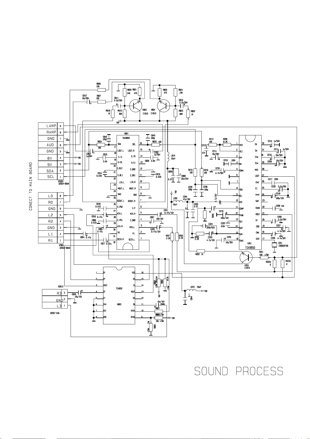
3 KP2708UYSYCLB-00 KP2708UY SOUND PROCESS BOARD ASS'Y SET 1
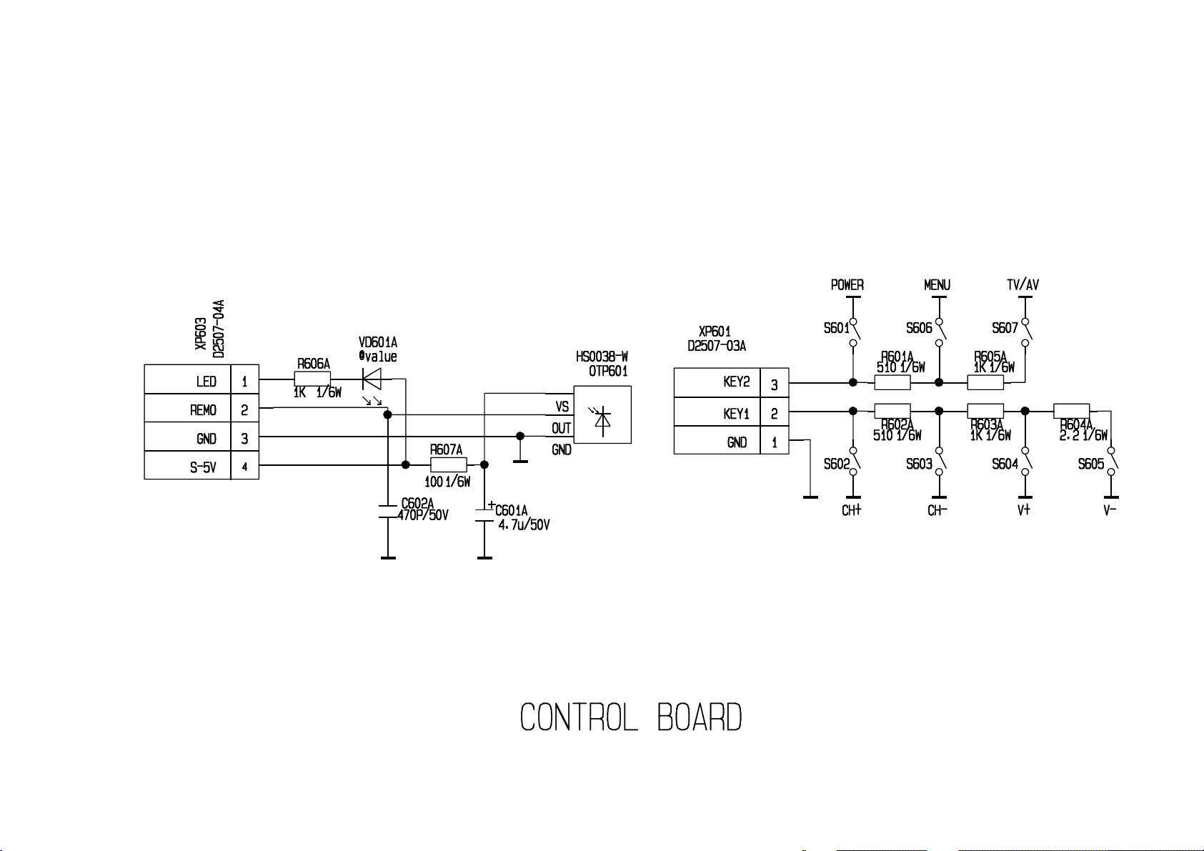
4 KP2708UYAJB-00 KP2708UY KEY RECEIVING BOARD ASS'Y SET 1
5 KP2708UYCDAVB-00 KP2708UY ASIDE AV BOARD ASS'Y SET 1
6 11001452 POWER FILTER LCL-246 PCS 2
7 13002004 *COATING QUICK-FUSED RESIS.RF10D-1W0.33ΩK/A PCS 1
8 13002636 GLASSGLAZE TRIMMER POTENTIOMETER WI06-2B-A202L PCS 1
9 13003642 FUSED RESIS. RF1S-1W0.33ΩJ-KOA/#U PCS 1
10 13003714 *NTC 5D2-14-5Ω-K-270V-ISHIZUK/# PCS 1
11 13003792 *COATING QUICK-FUSED RESIS.RF10B-1W0.33ΩK/L15-A PCS 2
12 13003891 *COATING QUICK-FUSED RESIS.RF10D-2W2.7ΩJ/L25-A PCS 1
13 13004803 *NTC-S237/5.0-5ΩM265V-SIEMENS/# PCS 1
14 13005314 *HIGH VOLTAGE GLASSGLAZE RESIS. PCS 2
15 14000480 *METALIZED POLY.CAP.CL21-250V104K/10 PCS 1
16 14000710 *POLYPROPYLENE CAP.CBB12-400V223J/10 PCS 1
17 14000761 *TERRACE META.POLY.CAP.CL23B-100V224K/5 PCS 1
18 14000778 *METALIZED POLYPROPYLENE CAP.CBB81-1600V272J/15 PCS 1
19 14000833 *METALIZED POLY.CAP.CL21-630V333K/10 PCS 1
20 14000854 *POLYPROPYLENE CAP.CBB12-200V364J/20 PCS 1
21 14000950 *TERRACE META.POLY.CAP. CL23B-63V-474K/5 PCS 1
22 14000954 *TERRACE META.POLY.CAP. CL23B-100V474K/5 PCS 2
23 14001014 *METALIZED POLYPROPYLENE CAP.CBB81-1600V682J/20 PCS 1
24 14001028 *METALIZED POLYPROPYLENE CAP.CBB81-1600V752J/20 PCS 1
25 14001256 *TV CERAMIC CAP.CT1-500V-2B4-103M/b7.5 PCS 1
26 14001758 *AC CERAMIC CAP.CT81-250VAC-2E4-222MYA/b12.5A PCS 1
27 14001776 *TV CERAMIC CAP.CT81-2KV-Bn222J/b10 PCS 1
28 14002241 *HIGH FREQUENCE ELEC.CAP.CD288-160V227T/1940 PCS 1
29 14002355 *HIGH FREQUENCE ELEC.CAP.CD288-160V336T/1225 PCS 1
30 14002403 *TV CERAMIC CAP.CT81-2KV-Bn821J/b7.5 PCS 1
31 14002474 *LARGE CAN NON-POLARIZED CAP.CDS-50V475M/1630 PCS 1
32 14002488 *TV CERAMIC CAP.CT81-1KV-2B4-471K/b7.5 PCS 1
33 14002494 *TV CERAMIC CAP.CT81-2KV-Bn471K/b7.5 PCS 1
34 14003359 ANTI-INTERFERENCE FILM.CAP.MKT61-275VAC104M/15U PCS 2
35 14003535 *HIGH FREQUENCE ELEC.CAP.CD288-250V475T/1220 PCS 1
36 14003913 * CERAMIC CAPCT1-500V-2E4-472Z-Ф9.6/b7. PCS 2
37 14003975 *LARGE CAN TYPE ALUMINUM ELEC.CAP. PCS 1
Page 27

Spare Part List
38 14004022 *AC CERAMIC CAP.CT81-250VAC-2B4-471-K-YA/b10A PCS 2
39 14005304 *METALIZED POLYPROPYLENE CAP.CBB21B-250V364J/20 PCS 1
40 14005596 *HIGH FREQUENCE ELEC.CAP.CD288-63V477M/1 PCS 1
41 14005598 *HIGH FREQUENCE ELEC.CAP.CD288-25V477M/1 PCS 1
42 14005599 *HIGH FREQUENCE ELEC.CAP.CD288-16V108M/ PCS 1
43 15000086 *INDUCTANCE COIL L161-001-160μHK/L7.5 PCS 1
44 15000099 HORI. LINEARITY COIL HXC-19A/L7.5 PCS 1
45 15000209 *INDUCTANCE COIL L791-001-790μHK/L7.5 PCS 1
46 15000213 *INDU.WITH COLOR CODES LGB0606-R82K/ PCS 1
47 16000165 *SWITCHING DIODE IN4148-0.1A75V4ns/H PCS 27
48 16000723 *LED BT-H202YXN-31-R LUCID Φ3 PCS 1
49 19002610 IC MC7805CT-ONSEMI/# PCS 1
50 19002619 IC MC7808CT-ONSEMI/# PCS 1
51 20000002 *CERAMIC TRAP FILTER XT4.5MB PCS 1
52 20000274 CERAMIC RESONATOR CSB503F58 MURATA /# PCS 1
53 22000340 *QUARTZ CRYSTAL JA120-12M-30-20PF-20Ω PCS 1
54 23000226 TOUCH SWITCH KFC-A06-L4-4.5×6.5-4.3B PCS 6
55 23000481 TOUCH SWITCH KFC-A07-10H070 PCS 1
56 25000150 S TERMINAL JACK TCS-56-WK PCS 1
57 25000187 THREE HOLE AV SOCKET WK3-8.4-13 PCS 1
58 25000924 SIX HOLE AV SOCKET AV6-8.4-1 PCS 1
59 25001622 SOCKET ZAV-534V-01 PCS 1
60 36014984 AC LINE CORE CLIP 254*000210/00-F PCS 1
61 36015337 BRACKET 229*ST296810/100C PCS 2
62 36018318 SPEAKER BRACKET229*P3411T10/101 PCS 2
63 36019002 BRACKET 229*T292610/100C PCS 1
64 36027854 MODEL PLATE 412*CFT271610/01-AKAI PCS 1
65 36027895 PLATE384*CFT271610/01-AKAI PCS 1
66 37008152 NAME PLATE 401*CFT271610/01-AKAI PCS 1
 Loading...