

Page 1
DVD PLAYER
Model:
A-4182
A-4183
Page 2

SERVICE MANUAL
1. The System Block Diagram&the Block’s Function Description
2. Schematic Circuit Diagram
3. Critical Components List
4. IC Date Sheet&IC Description
5. Service Tools and Equipment
Page 3
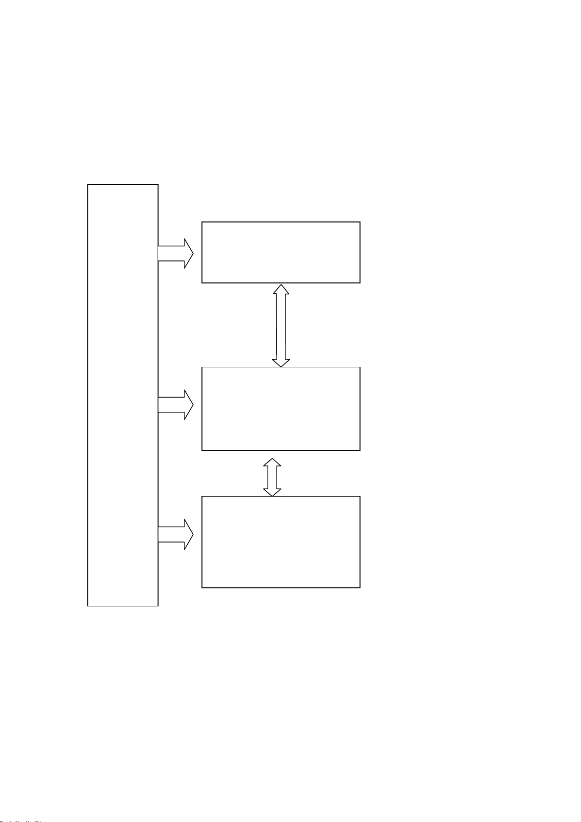
1. The System Block Diagram & the Block’s Function Description
DVD System Block
LOADER
LN9815H2
HITICHI 1200
AC to DC
POWER
BOARD
(TEA1521P)
DECODE BOARD
MTK1389E
CONTROL BOARD
HD6928+GT60241
Page 4
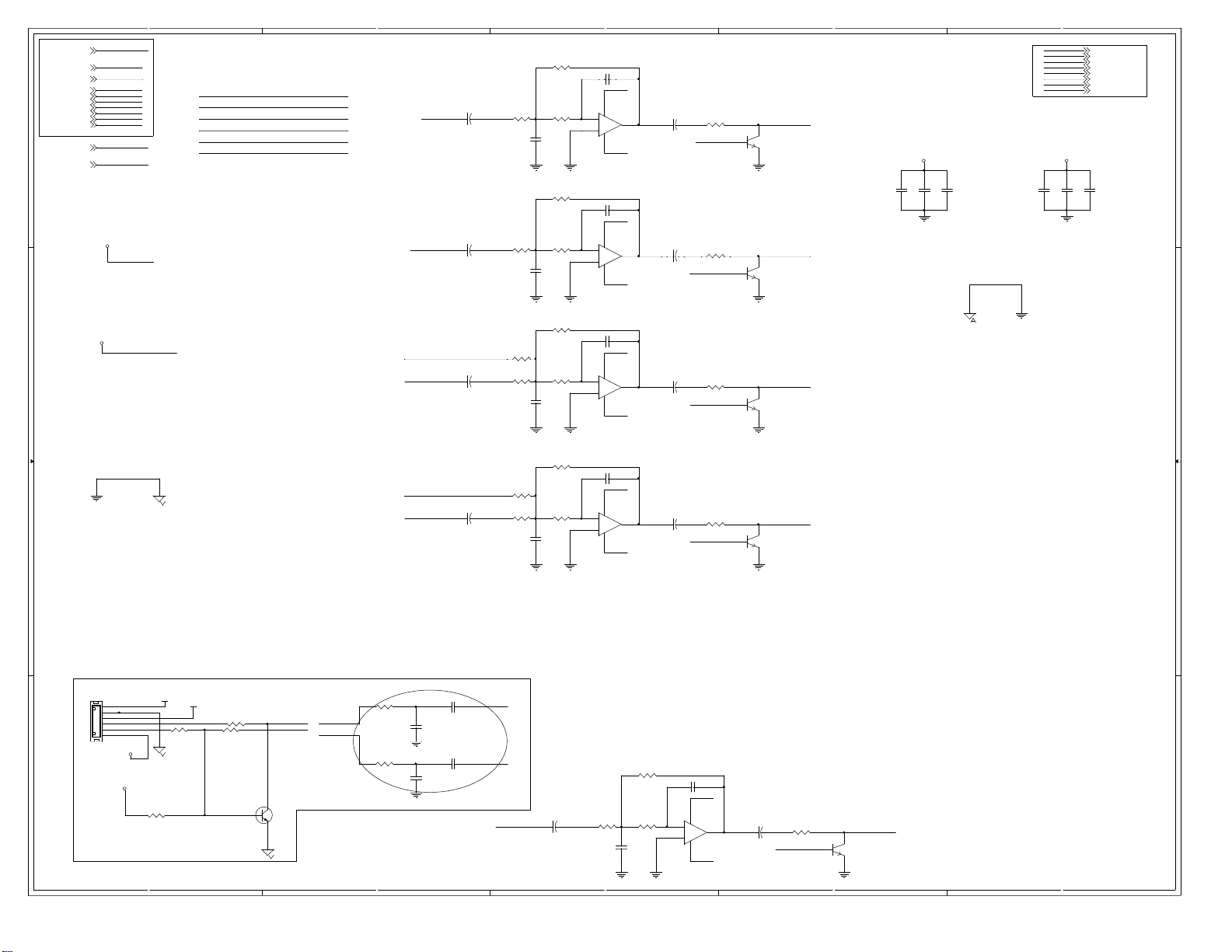
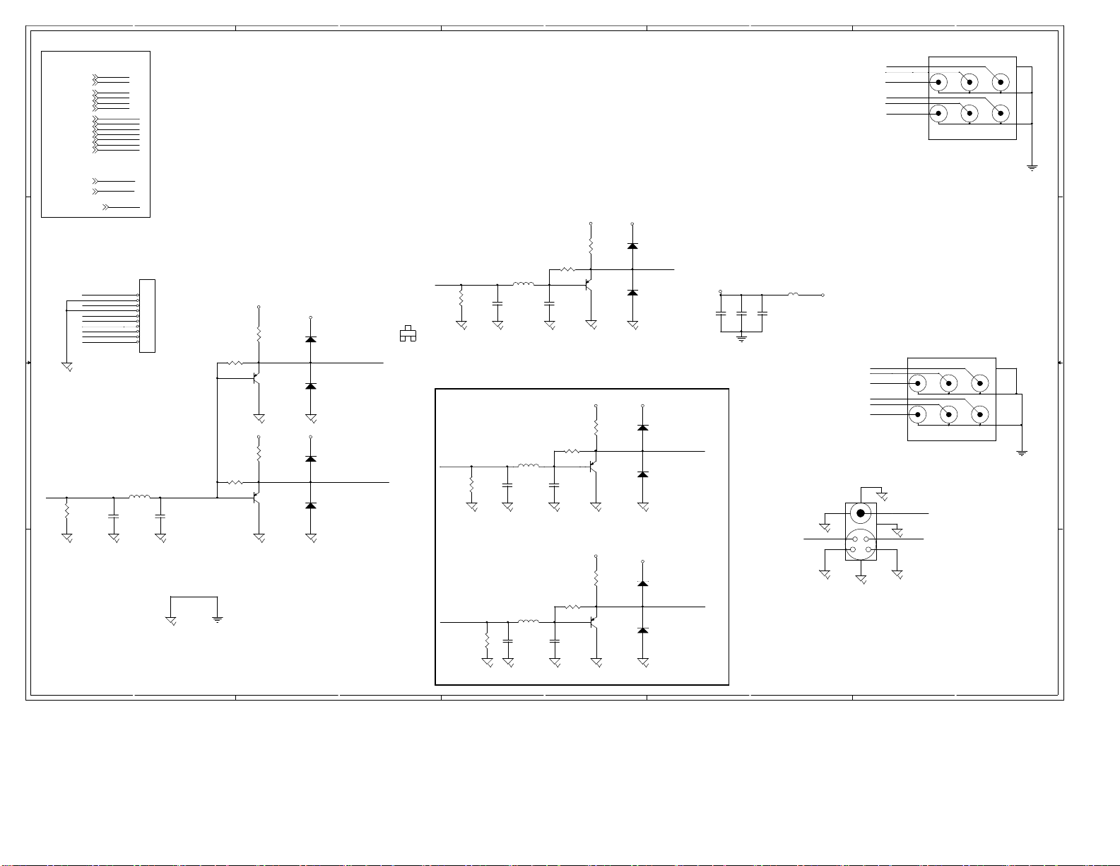
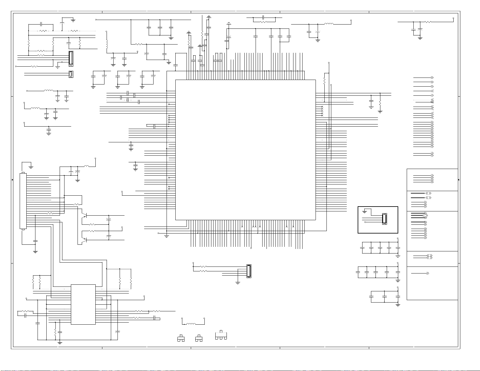
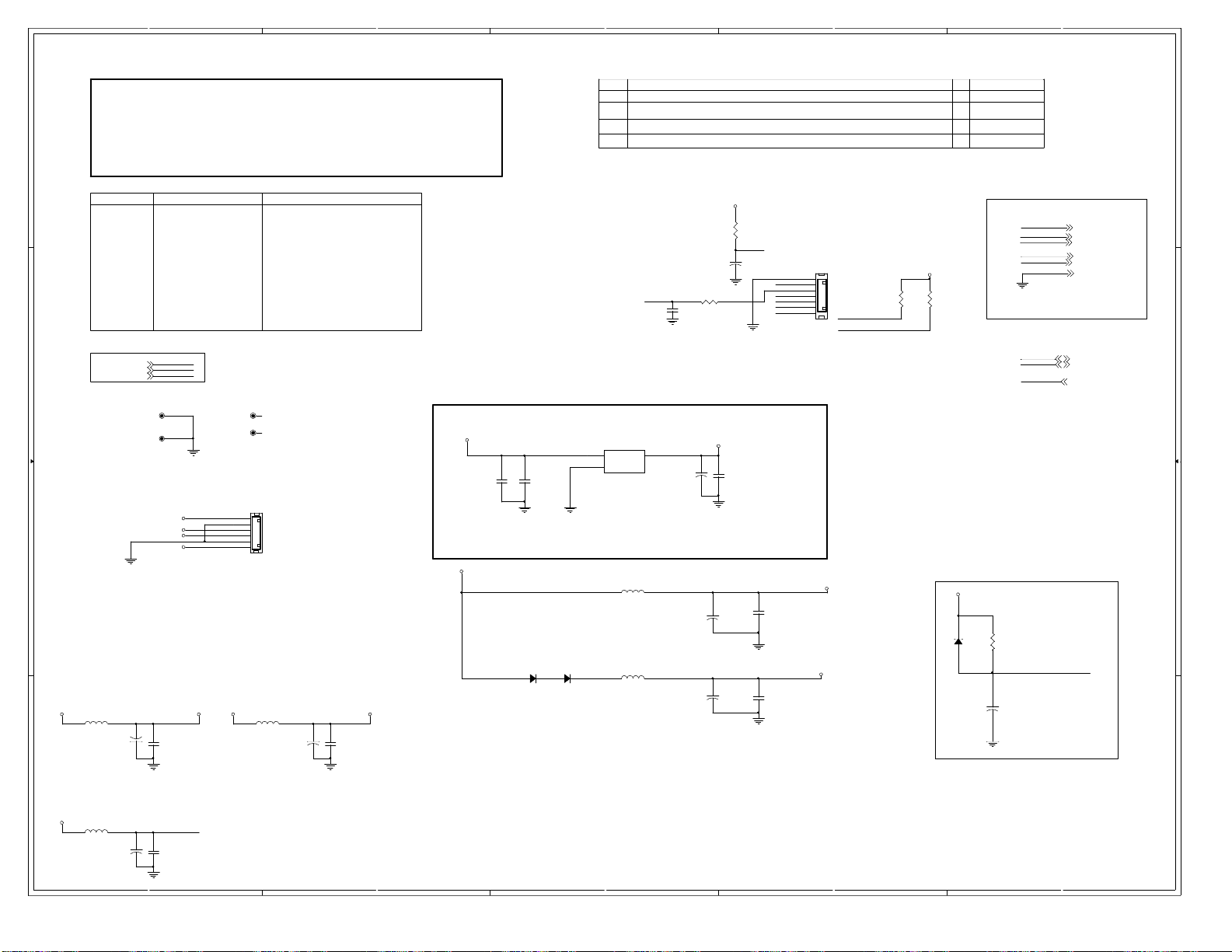
2. Schematic Circuit Diagram
[1,2,4]
VCC
DV33[1,2,3]
GND[1,2,3,4]
AL[2]
AR[2]
ALS[2]
ARS[2]
ACENTER[2]
ASUBW[2]
MUTE_DAC[2]
D D
MUTE_O[2]
OK-POINT[2]
VCC
DV33
C C
B B
VCC
DV33
GND
AL
AR
ALS
ARS
ACENTER
ASUBW
MUTE_DAC
MUTE_O
OK-POINT
5
CENTER1ACENTER
AL LMAIN1
ASUBW SUBW1
VCC
DV33
LSUR1ALS
RMAIN1AR
RSUR1ARS
4
R94
31
R104
R103
10
R113
10
R172 0
R117
10
R1730
R125
10
5.1k
k
C68
1000pF
R112
31k
R114
5.1k
k
C73
F
1000p
R116
31
R118
5.1k
k
C77
F
1000p
R122
31
R126
5.1k
k
C83
1000pF
SUBW1
AKIN2
LMAIN1
AKIN1
RMAIN1
RSUR1
C66 10uF/16v
+
C71 10uF/16v
+
C75 10uF/16v
+
C79 10uF/16v
+
3
k
C65 100pF
-12V
U12A
-
2
1
+
3
NJM4558 OPA
8 4
+12V
C70 100pF
-12V
4
U12B
-
6
7
+
5
NJM4558 OPA
8
+12V
k
C74 100pF
-12V
U13A
-
2
1
+
3
NJM4558 OPA
8 4
+12V
k
C78 100pF
-12V
4
U13B
-
6
7
+
5
NJM4558 OPA
8
+12V
C67 10uF/16v
+
C72 10uF/16v
+
C76 10uF/16v
+
C80 10uF/16v
+
A_MUTE
A_MUTE
A_MUTE
R107
0
10
R115
10
0
A_MUTE
R119
10
0
R127
0
10
RSCH
2
Q12
1
3
SUB
2
Q13
1
3
LCH
Q14
1
3 2
H
RC
2
Q16
1
3
2
CB57
CB56
CB58
0.1uF
0.1uF
0.1uF
CB59
0.1uF
AKIN1
AKIN2
LCH
RCH
LSCH
RSCH
CENT
SUB
1
-12V+12V
CB60
0.1uF
AKIN1 [2]
AKIN2 [2]
LCH [4]
RCH [4]
LSCH [4]
RSCH [4]
CENT [4]
SUB [4]
CB61
0.1uF
MUTE
HEAD6-100
6x1 W/HOUSING
J11
6
5
4
3
2
1
A A
OK-POINT
+VCC
+VCC
VCC
+P12V
-P12V
MICIN
R79
4K7
5
R81 1k
R751K
MUTE_O
R77100
!"#!"
3
2
1
MIC INPU T
R140 100
MIC_IN
MIC_IN
MIC_IN
R144 100
Q7
1
200
4
C88 0.1uF
C90
0.33uF
C93 0.1uF
C95
0.33uF
R & C closed to MT1389E
AKIN1
AKIN2
LSUR1
C91 10uF/16v
+
R141
10
R139
k
31
C89 100pF
-12V
R142
5.1k
k
C94
F
1000p
3
U15B
-
6
7
+
5
NJM4558 OPA
8 4
+12V
C92 10uF/16v
+
A_MUTE
R143
10
0
LSCH
2
Q19
1
3
2
1
Page 5
5
VCC
VCC[1,2,5]
GND[1,2,3,5]
GND
CVBS
CVBS[2]
R
R[2]
G
G[2]
VB[2]
D D
VB
AS
LCH
RCH
LSCH
RSCH
CENT
SUB
PDIF
ASPDIF[2]
LCH[5]
RCH[5]
LSCH[ 5]
RSCH[5]
CENT[5]
SUB[5]
4
3
2
COAXIAL
R/V
B/U
RC
H
Y
G/
LCH
1
P10
5
4
6
7
8
9
RCA-AV6
3
1
2
A21
[2]
[2]
RGB_SWITCH
[2]
C C
B B
CVBS
R90
15
0,1%
A A
RGB_SWITCH
FS0
FS0
H
RC
LCH
B/U
ASPECT
Y
G/
R/V
RGB/CVBS#
SCART_CVBSO
SCART,PH2.0-10A
C104
P
47
A21
L28 1.8uH
$%&'()*+,-./012
J9
1
2
3
4
5
6
7
8
9
10
C105
P
47
R159
R88
+5VV
0/NC
+5VV
0/NC
+5VV
2
D22
1N4148
1
SCART_CVBSO
Q23
390
Q10
390
2
+5VV
D23
1N4148
1
2
D25
1N4148
1
2
D27
1N4148
1
6
6
3906
B
CVBSO
G
R78
15
0,1%
C
E
C100
47
L27 1. 8uH
P
Note:Video is the high resistance output
VB
C57
R84
15
0,1%
47
P
R
R91
15
C63
0,1%
47
L23 1.8u H
L26 1.8uH
P
Modify3Value
+5VV
R74
75,1%
0/NC
R76
C101
47
P
+5VV
R80
0/NC
R82
C58
47
P
+5VV
R87
0/NC
R89
C64
47
P
+5VV
2
D20
1N4148
1
G/
Y
2
Q6
3906
D21
1N4148
1
+5VV
2
D24
1N4148
1
SC
2
+5VV
D26
1N4148
1
2
D28
1N4148
1
SY R/V
2
D29
1N4148
1
Q8
6
390
Q11
390
6
+5VV
C48
0.1uF
B/U
+5VV
C49
1uF
C50
47uF/16v
L20
VCC
10u
H
P11
SY SC
8
VIDEOPORT
7
CENT
SUB
RC
RSCH
LCH
LSCH
P8
5
4
H
6
7
8
9
RCA-AV6
3
1
2
COMPOSIT
CVBSO
56
9
34
21
S-VIDEO
5
4
3
2
1
Page 6

5
DV33[1,2,5]
GND[1,2,4,5]
MA[0..11][2]
BA[0..1][2]
DQM[0..1][2]
DCLK[2]
DCKE[2]
D D
CAS#[2]
RAS#[2]
WE#[2]
CS#[2]
DV33
GND
MA[0..11]
BA[0..1]
DQM[0..1]
DCLK
DCKE
CAS#
RAS#
WE#
CS#
DRAM
PCE#[2]
PCE#
PRD#[2]
PRD#
PWR#[2]
PWR#
VCC
VCC[1]
A[0..21][2]
DCS#
DR
AS#
AS#
DC
DWE# WE#
C C
DB
A0 BA0
DBA1 BA1
SDCKE
SDCLK
A[0..21]
FLAS
H
RN1
7 8
5 6
3 4
1 2
33
x4
R60 33
R61 33
R62 33
R63 33
CS#
RAS#
CAS#
DCKE
DCLK
C107
10PF
U8
MA0
23
MA1
MA2
MA3
MA4
MA5
B B
MA6
MA7
MA8
MA9
MA10
MA11
DB
DB
SDCLK
SDCKE
DCS#
DR
DC
DWE#
DQM0
DQM1
A A
A0
24
A1
25
A2
26
A3
29
A4
30
A5
31
A6
32
A7
33
A8
34
A9
22
A10/AP
35
A11
A0
20
BA0/A13
A1
21
BA1/A12
38
CLK
37
CKE
19
CS
AS#
18
RAS
AS#
17
CAS
16
WE
15
DQML
39
DQMH
36
NC
40
NC
54
VSS
41
VSS
28
VSS
ESM
TSOP(II)-54/SMD
DQ0
DQ1
DQ2
DQ3
DQ4
DQ5
DQ6
DQ7
DQ8
DQ9
DQ10
DQ11
DQ12
DQ13
DQ14
DQ15
VCC
VCC
VCC
VCCQ
VCCQ
VCCQ
VCCQ
VSSQ
VSSQ
VSSQ
VSSQ
T M12L64164A/N.C
DQ7
2
DQ6
4
DQ5
5
DQ4
7
DQ3
8
DQ2
10
DQ1
11
DQ0
13
DQ8
42
DQ9
44
DQ10
45
DQ11
47
DQ12
48
DQ13
50
DQ14
51
DQ15
53
SD33
1
14
27
SD33
3
9
43
49
6
12
46
52
FVCC
R68
10k
FVCC
PCE#
PRD#
PWR#
4
A20 AA20
R64 NC
R66 NC
A1
A2
A3
A4
A5
A6
A7
A8
A9
A10
A11
A12
A13
A14
A15
A16
A17
A18
A19
AA20
AA21
U9
25
A0
24
A1
23
A2
22
A3
21
A4
20
A5
19
A6
18
A7
8
A8
7
A9
6
A10
5
A11
4
A12
3
A13
2
A14
1
A15
48
A16
17
A17
16
A18
9
A19
10
A20
26
CE
28
OE
11
WE
12
RESET
IC FLASH MX29LV800 8Mb
16Mb
32Mb
D15/
WP/
MA0
MA1
MA2
MA3
MA4
MA5
MA6
MA7
MA8
MA9
MA10
DB
A0
SDCLK
SDCKE
DB
A1
AS#
DR
AS#
DC
DWE#
DQM0
DQM1
D0
D1
D2
D3
D4
D5
D6
D7
D8
D9
D10
D11
D12
D13
D14
A-1
ACC
BYTE
VCC
GND1
GND2
U7
21
A0
22
A1
23
A2
24
A3
27
A4
28
A5
29
A6
30
A7
31
A8
32
A9
20
A10
19
BA/A11
35
CLK
34
CKE
18
CS
17
RAS
16
CAS
15
WE
36
DQMH
33
NC
37
NC
26
VSS
50
VSS
ESM
AA21A21
AD0
29
AD1
31
AD2
33
AD3
35
AD4
38
AD5
40
AD6
42
AD7
44
30
32
34
36
39
41
43
A0
45
R69 0
14
47
37
27
46
DQ0
DQ1
DQ2
DQ3
DQ4
DQ5
DQ6
DQ7
DQ8
DQ9
DQ10
DQ11
DQ12
DQ13
DQ14
DQ15
VCC
VCC
VCCQ
VCCQDQML
VCCQ
VCCQ
VSSQ
VSSQ
VSSQ
VSSQ
T M12L16161A-7
3
DV33 SD33
L29 FB
DQ0
2
DQ1
3
DQ2
5
DQ3
6
DQ4
8
DQ5
9
DQ6
11
DQ7
12
DQ8
39
DQ9
40
DQ10
42
DQ11
43
DQ12
45
DQ13
46
DQ14
48
DQ15
49
SD33
1
25
SD33
7
1314
38
44
4
10
41
47
FVCC
FVCC
CB53
0.1uF
FVCC
CB52
0.1uF
C0603/SMD
R70
10k
PCE#
SD33
+
CB43
0.1uF
CE25
47uF/16v
3.3
5V
CB37
CB38
0.1uF
0.1uF
CB45
CB44
0.1uF
0.1uF
BO
M
DV33 FVCC
V
VCC
45
R85 0
R111 0
CB46
0.1uF
CB39
0.1uF
2
CB47
0.1uF
+
CE26
47uF/16v
CB40
0.1uF
CB48
0.1uF
CB50
0.1uF
CB41
0.1uF
CB49
0.1uF
CB29
0.1uF
CB51
0.1uF
SD33
SD33
R65
R67
1k
1k
U11
1
VCC
NC
2
NC
3
NC
SCL
4 5
GND SDA
EEPROM 24C16
SOP8/SMD
1
DRA
FLAS
M
H
DQ[0..15]
AD[0..7]
SCL
SDA
DQ[0..15][2]
AD[0..7][2]
SCL[2,3]
SDA[2,3]
IIC
SD33 [2]
SCL
SDA
SD33SD33
SD33
8
GND
7
WP
SCL
6
SDA
5
4
3
2
1
Page 7
5
RFV33
C16
2200p
J2
PH2.0-4A
J15
PH2.0-2A
C28
F
6800p
C0603/SMD
CB62
0.1uF
U4
VOTK+
VOTKVOLD+
VOLDPGND
VNFTK
PVCC2
PREGND
VINLD
CTK2
CTK1
VINTK
BIAS
STBY
F
+
RFV33
ADIN
OPOP+
R17
680
k
V1P4
CB14
0.1uF
VCC
L38 FB
EC1
uF/16V
100
Very Important
to reduce
Noise
Q30
3
855
0
2
1
R1784.7
R179 4.7
Q31
1
0
855
2
3
14
VOFC+
13
VOFC-
12
VOSL+
11
VOSL-
10
PGND
9
PVCC1
8
VCC
2930
G1G2
7
VNFFC
6
VOSL
5
VINSL-
4
VINSL+
3
CF2
2
CF1
1
VINFC
DV33
L10
1.8uH
ADACVDD3
+
CE15
47
uF/16v
V2P8
CB15
CE16
+
0.1uF
uF/6.3v
47
B
C29 1uF
A
D
C31 1uF
C
C32 1uF
RFO
C
D
A
B
RFVDD3
CB18
0.1uF
V18
LDO2
EC2
+
47
uF/16V
DV33
EC3
+
47
uF/16V
LDO1
FF+
R44
1
SP
-
SP+SL-
V1P4
FOSO
CE24
+
47
uF/16v
C4 2200pF
R11 680k
R15
k
150
R20 NC
-
R23 1
SP
D D
+
SP
LIMIT
DV33
R24 10k C26
SL+
SL-
DV33
V18
6
2
TOP
5
2
MO_VCC
CB64
0.1uF
R42
1
C43
150p
24
23
22
21
20
19
18
17
16
15
14
13
12
11
10
9
8
7
6
5
4
3
2
1
L37 F B
100
F
L11 10uH
100uF/16v
CE36
uF/16v
V20
E
F
D
A
B
C
RFO
MDI1
R177 10
MDI2
R43
1
SL+
CB34
0.1uF
+
DV33
C C
J5
B B
A A
R51 20k
CE19
CB17
0.1uF
FMSO
TRSO
V1P4
STBY
BE
OPO
R16
150
k
AD/SMD/0805
AADVDD3DV33
+
RFV33
C108
0NF
10
RFV18
T-
T+
R58
CB36
10
k
0.1uF
5
C5
0.1uF/NC
R12 0
1
2
3
4
2
1
R176 10
15
16
17
18
19
20
21
22
23
24
25
26
27
28
4
C7
C6
0.01uF
0.1uF
R19
6.8
ADACVDD3
CE14
+
100
C36
0.1uF
STBY
MO_VCC
CB16
0.1uF
C109 1uF
A2
A3
A4
A5
A6
A7
A8
A18
A19
4
V1P4
V2P8
V20
V1P4
OPO
OPOP+
DMO
FMO
TROPEN
TRO
FOO
ADIN
DV33
R53
20k
C44
150p
uF/16v
+
CE18
47
F
uF/6.3v
TEZISLV
C21
F
6800p
C0603/SMD
C15 closed to Pin189/190
V20
CE17
+
uF/6.3v
47
C30 1uF
C33 1uF
E
F
MDI1
MDI2
LDO2
LDO1
V18
R45
1
R52
10k
R55 20k
PLLVDD3
CB13
0.1uF
DMSO
RFVDD3
C8
2200p
1
AGND
2
DVDA
3
DVDB
4
DVDC
5
DVDD
6
DVDRFIP
7
DVDRFIN
8
MA
9
MB
10
MC
11
MD
12
SA
13
SB
14
SC
15
SD
16
CDFON
17
CDFOP
18
TNI
19
TPI
20
MDI1
21
MDI2
22
LDO2
23
LDO1
24
SVDD3
25
CSO/RFOP
26
RFLVL/RFON
27
SGND
28
V2REFO
29
V20
30
VREFO
31
FEO
32
TEO
33
TEZISLV
34
OP_OUT
35
OP_INN
36
OP_INP
37
DMO
38
FMO
39
TROPENPWM
40
PWMOUT1/ADIN0
41
TRO
42
FOO
43
FG/ADIN1
44
GPIO0/VSYNC#
45
GPIO1/HSYNC#
46
GPIO2
47
IOA2
48
DVDD18
49
IOA3
50
IOA4
51
IOA5
52
IOA6
53
IOA7
54
HIGHA0
1
B
F
4
P
1
V
k
0
0
1
k
5
1
F
3
p
1
F
0
R
u
0
1
0
.
1
0
8
1
0
R
2
F
C
u
3
F
3
u
0
1
.
.
3
0
0
D
D
V
F
R
0.1uF
6
1
2
5
5
VCC MO_VCC
C
3
E
5
1
2
3
D
D
V
A
8
1
A
O
I
6
5
L31 F B
F
E
R
I
9
1
A
O
I
2
2
C
3
4
1
1
2
2
C
G
F
R
#
R
W
O
I
7
8
5
5
#
R
6
1
W
A
P
DV33
G
2SK301
3
2
7
C
2
C
1
0
9
2
1
1
1
0
2
2
2
2
P
P
D
N
L
S
S
N
P
O
O
G
T
F
R
R
C
7
6
3
A
A
D
H
H
D
6
G
G
I
I
V
1
D
H
A
H
1
2
9
0
6
6
6
5
5
4
3
1
1
1
A
A
A
R54 10k
R50 10k
D
2
3
1
F
u
1
.
0
8
0
2
C
Z
F
R
H
5
A
H
G
I
H
3
6
2
1
A
S
82N3904
F
u
1
.
0
C
.
9
F
p
0
2
7
1
C
7
0
2
C
C
A
D
P
P
R
R
F
F
R
R
N
/
C
F
u
7
4
.
0
0
1
C
3
D
D
V
F
R
6
0
2
3
D
D
V
F
R
+
5
1
C
F
F
u
u
7
7
4
4
0
0
.
.
0
0
3
3
D
D
D
D
N
V
5
4
V
F
L
2
2
F
T
L
I
C
C
R
P
J
4
7
1
3
2
5
0
2
S
S
V
C
D
A
6
0
9
8
0
9
0
9
9
0
0
9
0
2
1
1
2
1
1
2
2
2
3
3
P
P
S
P
N
N
I
I
L
D
S
D
O
F
O
F
X
V
D
D
F
F
P
P
L
E
V
V
P
P
L
L
L
L
C
L
L
C
P
L
A
D
P
D
A
I
MT1389E
Pin Assignment v1.4
3
2
1
4
A
A
A
A
#
#
0
S
E
H
H
S
H
H
2
1
1
2
S
0
A
O
C
A
G
G
G
G
I
I
I
I
H
H
H
4
5
6
6
6
6
0
1
1
1
9
A
A
A
H
7
6
0
2
A
1
O
O
I
I
9
8
6
6
#
1
E
A
C
P
B
2SB113
V
D
D
D
O
O
A
A
A
I
D
I
1
2
5
3
0
4
7
7
7
7
7
7
#
D
R
0
3
1
2
P
D
D
D
D
A
A
A
A
TRIN
TROUT
LOAD+
LOAD-
2
C
3
C
E
2
C11
10uF/6.3v
O
F
T
I
J
5
9
1
N
O
F
F
T
T
I
I
J
J
4
3
D
D
A
A
6
7
4
D
A
3
JITFO
C3 3 90pF
R9 750k
C12
4.7uF/10v
O
I
X
X
3
3
D
D
R
D
D
E
V
V
T
8
C
C
N
1
A
A
E
V
S
D
D
F
L
C
L
I
A
A
R
A
A
L
A
A
T
X
7
0
1
9
4
8
3
2
6
5
8
9
8
8
9
8
9
9
8
9
1
1
1
1
1
1
1
1
1
1
I
)
2
1
0
8
2
8
O
L
A
T
X
5
D
A
7
8
7
7
6
5
D
D
A
A
3
M
R
1
1
A
A
D
D
L
C
T
T
T
D
D
D
A
D
V
C
A
A
T
D
N
V
V
(
A
D
D
X
V
F
C
C
G
S
S
F
L
F
A
A
/
/
A
R
L
R
D
D
S
L
A
A
A
A
8
1
#
1
#
D
2
0
R
D
6
7
D
7
E
A
A
W
R
V
D
L
D
1
O
O
A
I
I
A
A
D
A
U
U
4
1
9
5
6
3
0
2
8
8
8
8
8
7
8
8
7
7
1
1
D
2
0
A
A
A
A
V18
5
4
J4
3
2
PH2.0-5A
1
JITFN
DACVDD3
C13
C14
1500pF
4.7uF/10v
3
3
D
D
D
M
W
D
V
1
B
U
S
S
R
R
A
A
A
4
3
2
8
8
8
1
1
1
)
1
S
A
W
R
T
S
A
(
A
F
D
R
S
/
A
R
A
3
2
3
D
_
_
1
1
D
P
P
V
D
U
U
7
9
8
8
8
8
K
C
S
O
/
I
V
2
C
V
L
N
N
V
L
D
I
I
D
P
A
K
K
A
A
A
A
A
1
4
3
9
5
7
0
2
6
8
7
8
7
7
7
7
7
7
8
7
1
1
1
1
1
1
1
1
1
1
1
1
2
2
P
S
D
D
M
S
S
A
N
N
S
D
D
C
I
I
S
S
V
C
V
V
V
K
K
V
L
V
L
L
D
D
A
A
L
L
L
C
C
A
A
P
P
A
P
A
A
A
A
A
D
D
A
A
7
4
0
6
1
6
4
5
5
_
_
_
_
_
_
_
_
O
I
3
3
1
1
3
1
1
3
P
P
P
P
P
P
P
P
P
U
G
U
U
U
U
U
U
U
4
1
2
8
9
5
3
0
7
6
9
9
9
9
9
9
9
9
9
9
T
E
N
S
O
I
O
_
O
L
E
B
A
P
L
D
T
C
-
T
A
D
D
X
C
K
S
U
R
S
D
X
R
V
S
T
M
T
V
O
S
CB11
0.1uF
CB12
0.1uF
G
B
V
R
3
3
D
D
S
D
D
B
V
V
V
C
C
C
A
A
D
D
5
7
9
4
8
0
6
3
1
6
6
6
6
7
6
7
6
6
1
1
1
1
1
1
1
1
1
S
B
B
S
A
A
Y
S
C
C
S
S
B
B
S
S
S
S
D
D
/
/
V
S
S
V
V
S
D
D
S
b
V
V
C
C
D
A
A
7
O
I
P
G
0
0
1
V
V
V
B
/
C
/
C
C
C
C
C
V
Y
B
A
A
A
A
A
S
C
/
/
D
D
D
D
D
r
Y
/
C
/
G
R
DACVDDC
MC_DATA
ASDATA3
ASDATA2
ASDATA1
ASDATA0
#
3
#
0
#
D
T
0
M
7
6
5
S
D
T
E
D
Q
V
D
D
R
N
R
C
P
I
R
D
I
D
R
R
I
8
5
6
3
7
4
1
2
0
0
0
0
0
0
0
0
1
1
1
1
1
1
1
1
#
0
T
7
6
5
M
S
Q
Q
Q
R
Q
R
I
D
D
D
D
U
FS
VREF
SPDIF
ALRCK
ACLK
ABCK
GPIO5
DVSS
GPIO4
GPIO3
DVDD18
RA4
RA5
RA6
RA7
RA8
RA9
RA11
CKE
DVDD3
RCLK
RA3
RA2
RA1
DVDD18
RA0
RA10
BA
BA
RCS#
RAS#
CAS#
RWE#
DQM1
RD
RD
DVSS
RD10
RD11
RD12
RD13
RD14
RD15
RD0
RD
RD2
RD
RD
U3
MT1389E
LQFP216/SMD
2
V18
SD33
DACVDD3
ASPDIF
RGB_SWITCH
FS0
MA4
MA5
MA6
MA7
MA8
MA9
MA11
DCKE
DCLK
MA3
MA2
MA1
MA0
MA10
1
BA
BA
0
CS#
RAS#
CAS#
WE#
DQM1
DQ8
DQ9
DQ10
DQ11
DQ12
DQ13
DQ14
DQ15
DQ0
DQ1
DQ2
DQ3
DQ4
SD33
FS
VREF
SD33
MUTE_DAC
CB25
0.1uF
TxD
RxD
CB20
0.1uF
TROUT
TRIN
LIMITV18
C34
0.1uF
RS-232
CB21
0.1uF
CB26
0.1uF
CB31
0.1uF
CB27
0.1uF
R26
2K
J3
4
3
2
1
PH2.0-4A
CB22
0.1uF
CB32
0.1uF
CB28
0.1uF
CB23
0.1uF
L30 10 UH
CE13
+
47
uF/16v
DV33
6
5
1
R
K
7
.
4
162
161
160
159
158
157
156
155
154
153
152
151
150
149
148
147
146
145
144
143
142
141
140
139
138
137
136
135
134
133
132
131
130
129
1
128
0
127
126
125
124
123
122
8
121
9
120
119
118
117
116
115
114
113
112
1
111
110
3
109
4
2
V18
DV33
DV33
APLLVDD3
CB24
0.1uF
CB30
0.1uF
CB33
0.1uF
CB10
0.1uF
1
OK-POINT
MUTE_O
FS0
URST#
DV33
GND
VSCK
VSDA
VSTB
PCE#
PWR#
MUTE_DAC
A[0..21]
AD[0..7]
PRD#
PWR#
PCE#
MA[0..11]
DQ[0..15]
BA[0..1]
DQM[0..1]
DCLK
DCKE
CAS#
RAS#
WE#
CS#
SCL
SDA
AS
1
R10
10
CE12
+
100
DC100B
I/O
SD33
VCC
IR
AKIN1
AKIN2
AL
AR
ALS
ARS
ACENTER
ASUBW
RGB_SWITCH
A21
CVBS
R
G
VB
VIDEO INT
FLASH
MEMORY
PDIF
AUDIO INT
uF/16v
I/O [1 ]
OK-POINT [5]
MUTE_O [5]
SD33 [3]
FS0 [5]
URST# [ 1]
VCC
DV33 [1,3 ,5]
GND [1,3,4,5]
IR [1]
AKIN1 [5]
AKIN2 [5]
VSCK [1]
VSDA [1]
VSTB [1]
PCE# [3]
PWR# [3]
AL [5]
AR [5]
ALS [5]
ARS [5]
ACENTER [5]
ASUBW [5]
MUTE_DAC [5]
RGB_SWITCH [4]
A21 [4]
CVBS [4]
R [4]
G [4]
VB [4]
ERFACE
A[0..21] [3]
AD[0..7] [3]
PRD# [3]
PWR# [3]
PCE# [3]
MA[0..11] [3]
DQ[0..15] [3]
BA[0..1] [3]
DQM[0..1] [3]
DCLK [3]
DCKE [3]
CAS# [3]
RAS# [3]
WE# [3]
CS# [3]
SCL [3]
SDA [3]
IIC
ASPDIF [4]
ERFACE
DV33
[1,4,5]
Page 8
5
4
3
2
1
COMMON1389E_HD60_V3
MT1389E (LQFP216) DVD MP Board for SANYO HD60PUH
1 INDEX & POWER, RESET
2 MT1389E
3 SDRAM & FLASH
D D
4 VIDEO OUT & AV-CON
5 AUDIO OUT - WM876
6
Rev
V1
Initial released. Modified from 3-SY1389DP1-V11
V2 Add SCART and VGA output 2005.03.01
Modify Video backend circuit.
V3
History
P#
Date
2005.01.19
2005.03.09
E
NAM
C
VC
DV3
3
RFV3
3
3 Laser Diode 3.3V
AV3
V1
8
3
SD3
+12
V
-12
V Audio -12V OP AMP.
AVDD
5
DVDD3
C C
VSCK[2]
VSDA[2]
VSTB[2]
E
TYP
Digital 5
Digital 3.3
Servo 3.3
Digital 1.8
Digital 3.3V SDRAM
Audio +12V
Audio 5V
Audio 3.3
VSCK
VSDA
VSTB
V
V
V
V
V
E
DEVIC
SUPPLY
E
MT1389
MT1389E
MT1389
E
OP AMP.
Audio DA
Audio DAC
VCC
R1
10
IRVCC
CE1
+
10
uF/10v
IR
C
R2 10
C1
100pF
IRVCC
VSCK
VSTB
VSDA
I/O
1
2
3
4
5
6
7
PH2.0-7A
J1
VSD A Pull UP
VSDA
I/O
SD33
R3
10
SD33
R21
10
k
k
Open IR1 , if used V FD
SCL
SDA
SD33
I/O
URST#
IR
DV33
VCC
GND
I/O [2 ]
URST# [ 2 ]
IR [ 2 ]
DV33 [2,3,5 ]
[ 2,4,5 ]
VCC
GND [2 ,3,4,5]
SCL
SDA
SD33 [3]
[2]
[2]
Reserved for testing
TP2
TP1
+VCC
+VCC
-P12V
+P12V
B B
-12V
CE4
CB4
+
100
uF/25v
0.1uF
FM1
FM2
CON2
1
2
3
4
5
6
TJC3-6A
HEAD6-100
+P12V-P12V
L35 F BL34 F B
CE5
+
100
uF/25v
CB5
0.1uF
+12V-12V
+12V
VCC
C2
uF/16v
10
DC100B
V33
V33
CB1
0.1uF
C0603/SMD
D11
V33
1N4007
D9
1N4007
U1
23
OUTIN
1
ADJ/GND
L32 F B
L33 F B
V33
CB6
CE6
+
100
uF/16V
0.1uF
RESET Circuit
DV33
CE2
+
100uF/16v
CE7
+
100
uF/16v
CB3
0.1uF
CB7
0.1uF
DV33
V18
V18
SD33
D3
1N4148
R6
k
10
URST#
CE9
+
uF/16v
10
DC100B
A A
+VCC
L36 F B
CE10
100
uF/16v
VCC
+
CB8
0.1uF
5
4
3
2
1
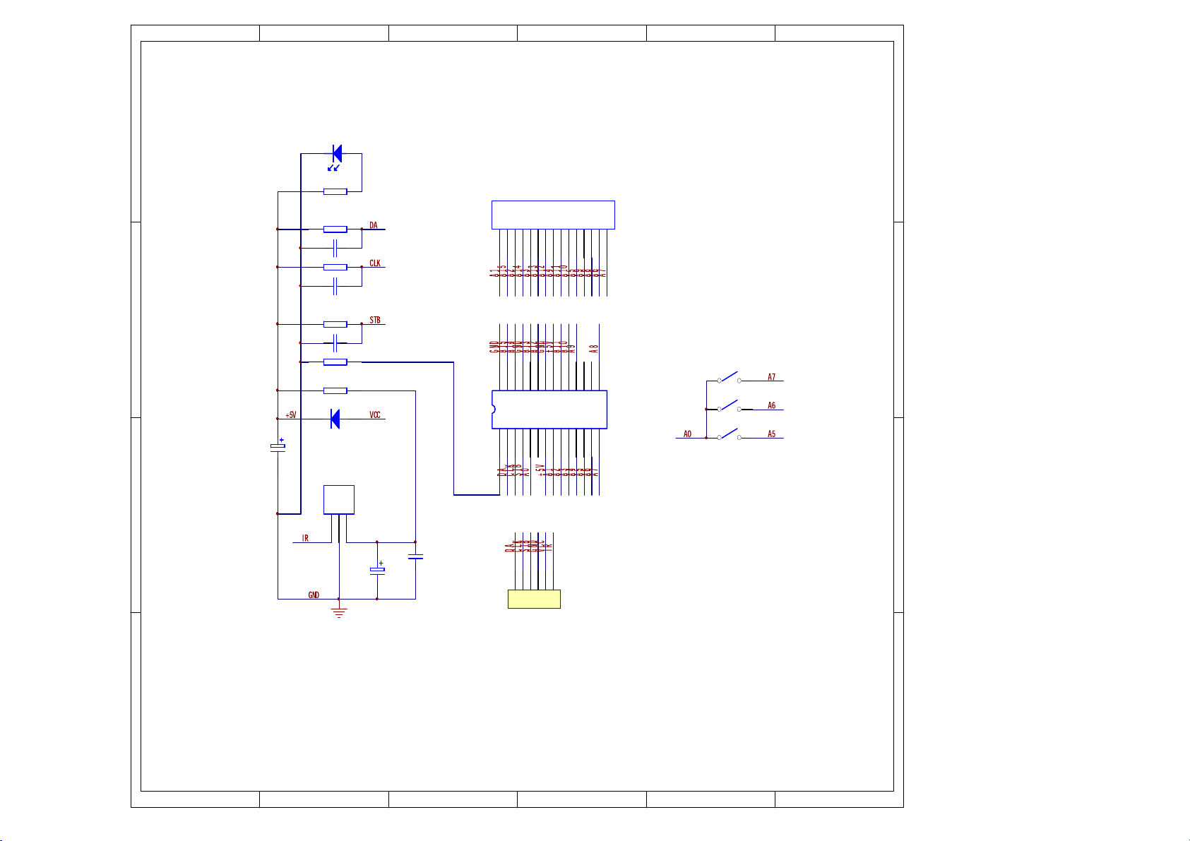
Page 9
21
3
4
5
6
D
2R
3
R
C
C
B
R
C
2
D
4
C
V61/FU0
22
R
DEL
1D
1R
K1
K0
1
1011C
K01
1
012
K01
4
1
013
5R
K51
6R
074
1004
ME
MER
S
1
86
8
9
7
1 0
6
5
4
3
1
2
2 4
2 5
2 6
2 7
2 8
1
2
3
4
5
1 1
1 2
1 3
1 4
1 5
2S
2 3
6
7
8
9
1 0
1 1
1 2
8
296DH
1 3
1 4 1 5
1U
1 6
1 7
1 8
1 9
2 0
2 1
2 2
3S
4S
D
C
B
6C
401
5C
V61/FU022
1
5
6
2
3
4
1NO
C
A
1 2 3 4 6
5
A
Page 10

1
2
3
4
5
6
D
V
A
5
2
0
F
L
2
1
C
N
A
I
S
A
C
B
C
W
I
N
6
D
2
2
X
1
1
4
3
F
L
R
4
0
I
D
4
N
1
7
0
3
I
0
D
4
N
7
0
1
R
K
7
0
4
0
N
7
2
I
D
0
4
4
I
0
D
4
N
7
0
1
2
C
1
1
3
4
10
3
K
1
C
I
1
12
E
A
T
1
P
5
2
R
2
C
0
0
1
K
0
1
3
1
/
K
C
1
/
F
2
U
2
V
0
0
4
5
D
H
7
1
0
E
R
8
7
6
8
R
5
.
5
6
K
D
6
5
R
I
4
N
84
1
1
3
R
0
1
7
C
4
3
71
8
1
0
R
1
K
C
3
3
7
4
D
8
L
T
1
5
T
2
2
I
1
4
8
4
N
C
9
F
U
0
2
2
D
7
L
3
7
C
4
4
8
1
N
I
F
U
0
2
2
D
0
1
8
C
1
L
0
6
3
C
2
0
2
F
2
U
0
V
-
2
1
V
2
1
+
+
V
5
1
0
F
0
2
U
1
2
D
9
9
R
3
V
9
.
2
8
D
C
B
A
1
2
3
4
5
6
A
Page 11

3.Critical Components List
Singing Appellation
S29AL008070TF102
V36V1616100TC-7
D5888S
89DE-E
MT13
TEA1521P
HD6928
GT-60241
IC
IC
C
I
C
I
IC
IC
DISPLAY
Page 12

4. IC Date Sheet & IC Description
Version 1.5 MT1389E
Specifications are subject to change without notice Pin Assignment
Abbreviations:
SR: Slew Rate
PU: Pull Up
PD: Pull Down
SMT: Schmitt Trigger
4mA~16mA: Output buffer driving strength.
Pin Main Alt. Type Description
RF Interface (26)
191 RFGND18 Ground Analog ground
192 RFVDD18 Power Analog power 1.8V
212 OSP Analog output RF Offset cancellation capacitor connecting
213 OSN Analog output RF Offset cancellation capacitor connecting
214 RFGC Analog output RF AGC loop capacitor connecting for DVD-ROM
rrent reference input. It generates reference current for
Cu
215 IREF Analog Input
216 AVDD3 Power Analog power 3.3V
1 AGND Ground Analog ground
2 DVDA Analog Input AC coupled input path A
3 DVDB Analog Input AC coupled input path B
4 DVDC Analog Input AC coupled input path C
5 DVDD Analog Input AC coupled input path D
6 DVDRFIP Analog Input AC coupled DVD RF signal input RFIP
7 DVDRFIN Analog Input AC coupled DVD RF signal input RFIN
8 MA Analog Input DC coupled main-beam RF signal input A
9 MB Analog Input DC coupled main-beam RF signal input B
10 MC Analog Input DC coupled main-beam RF signal input C
11 MD Analog Input DC coupled main-beam RF signal input D
12 SA Analog Input DC coupled sub-beam RF signal input A
13 SB Analog Input DC coupled sub-beam RF signal input B
14 SC Analog Input DC coupled sub-beam RF signal input C
15 SD Analog Input DC coupled sub-beam RF signal input D
16 CDFON Analog Input CD focusing error negative input
17 CDFOP Analog Input CD focusing error positive input
18 TNI Analog Input 3 beam satellite PD signal negative input
19 TPI Analog Input 3 beam satellite PD signal positive input
RF path. Connect an external 15K resistor to this pin and
AVSS
ALPC (4)
20 MDI1 Analog Input Laser power monitor input
2004/12/14
Page 13

MTK Confidential A
PRELIMINARY, SUBJECT TO CHANGE WITHOUT NOTICE MTK CONFIDENTIAL, NO DISCLOSURE
MT1389E
Pin Main Alt. Type Description
21 MDI2 Analog Input Laser power monitor input
22 LDO2 Analog Output Laser driver output
23 LDO1 Analog Output Laser driver output
Reference Voltage (3)
28 V2REFO Analog output Reference voltage 2.8V
29 V20 Analog output Reference voltage 2.0V
30 VREFO Analog output Reference voltage 1.4V
Analog Monitor Output (7)
24 SVDD3 Power Analog power 3.3V
25 CSO RFOP Analog output
26 RFLVL RFON Analog output
27 SGND Ground Analog ground
31 FEO Analog output Focus error monitor output
32 TEO Analog output Tracking error m onitor output
33 TEZISLV Analog output TE slicing Level
1) Central servo
2) Positive main beam summing output
1) RFRP low pass, or
2) Negative main beam summing output
Analog Servo Interface (8)
204 ADCVDD3 Power Analog 3.3V power for ADC
205 ADCVSS Ground Analog ground for ADC
206 RFVDD3 Power Analog power
207 RFRPDC Analog output RF ripple detect output
208 RFRPAC Analog Input RF ripple detect input (through AC-coupling)
209 HRFZC Analog Input High frequency RF ripple zero crossing
210 CRTPLP Analog output Defect level filter capacitor connecting
211 RFGND Ground Analog Power
RF Data PLL Interface (9)
195 JITFO Analog output Output terminal of RF jitter meter
196 JITFN Analog Input Input terminal of RF jitter meter
197 PLLVSS Ground Ground pin for data PLL and related analog circuitry
198 IDACEXLP Analog output Data PLL DAC Low-pass filter
199 PLLVDD3 Power Power pin for data PLL and related analog circuitry
200 LPFON Analog Output Negative output of loop filter amplifier
201 LPFIP Analog Input Positive input terminal of loop filter amplifier
202 LPFIN Analog Input Negative input terminal of loop filter amplifier
203 LPFOP Analog Output Positive output of loop filter amplifier
Motor and Actuator Driver Interface (10)
2
Page 14

MTK Confidential A
PRELIMINARY, SUBJECT TO CHANGE WITHOUT NOTICE MTK CONFIDENTIAL, NO DISCLOSURE
MT1389E
Pin Main Alt. Type Description
34 OP_OUT Analog output Op amp output
35 OP_INN Analog input Op amp negative input
36 OP_INP Analog input Op amp positive input
37 DMO Analog Output Disk motor control output. PWM output
38 FMO Analog Output Feed motor control. PWM output
39 TROPENPWM Analog Output Tray PWM output/Tray open output
40 PWMOUT1 ADIN0 Analog Output
41 TRO Analog Output
42 FOO Analog Output Focus servo output. PDM output of focus servo compensator
43
48,84,
132, 146
74, 120 DVSS Ground 1.8V Ground pin for internal digital circuitry
60,87,
108,137
149 DVSS Ground 3.3V Ground pin for internal digital circuitry
FG
(Digital pin)
DVDD18 Power 1.8V power pin for internal digital circuitry
DVDD3 Power 3.3V power pin for internal digital circuitry
ADIN1
GPIO
LVTTL 3.3V Input,
Schmitt Input, pull
up, with analog
input path for ADIN1
General Power/Ground (11)
st
General PWM output
1) 1
2) AD input 0
Tracking servo output. PDM output of tracking servo
compensator
1) Motor Hall sensor input
2) AD input 1
3) GPIO
Micro Controller and Flash Interface (48)
54 HIGHA0
66 HIGHA1
65 HIGHA2
64 HIGHA3
63 HIGHA4
62 HIGHA5
61 HIGHA6
InOut
4~16mA, SR
PU
InOut
4~16mA, SR
PU
InOut
4~16mA, SR
PU
InOut
4~16mA, SR
PU
InOut
4~16mA, SR
PU
InOut
4~16mA, SR
PU
InOut
4~16mA, SR
PU
Microcontroller address 8
Microcontroller address 9
Microcontroller address 10
Microcontroller address 11
Microcontroller address 12
Microcontroller address 13
Microcontroller address 14
3
Page 15

MTK Confidential A
PRELIMINARY, SUBJECT TO CHANGE WITHOUT NOTICE MTK CONFIDENTIAL, NO DISCLOSURE
MT1389E
Pin Main Alt. Type Description
InOut
59 HIGHA7
81 AD7
78 AD6
77 AD5
76 AD4
75 AD3
73 AD2
72 AD1
71 AD0
83 IOA0
69 IOA1
47 IOA2
49 IOA3
50 IOA4
51 IOA5
52 IOA6
53 IOA7
58 A16
4~16mA, SR
PU
InOut
4~16mA, SR
InOut
4~16mA, SR
InOut
4~16mA, SR
InOut
4~16mA, SR
InOut
4~16mA, SR
InOut
4~16mA, SR
InOut
4~16mA, SR
InOut
4~16mA, SR
InOut
4~16mA, SR
PU
InOut
4~16mA, SR
PU
InOut
4~16mA, SR
PU
InOut
4~16mA, SR
PU
InOut
4~16mA, SR
PU
InOut
4~16mA, SR
PU
InOut
4~16mA, SR
PU
InOut
4~16mA, SR
PU
Output
4~16mA, SR
PU
Microcontroller address 15
Microcontroller address/data 7
Microcontroller address/data 6
Microcontroller address/data 5
Microcontroller address/data 4
Microcontroller address/data 3
Microcontroller address/data 2
Microcontroller address/data 1
Microcontroller address/data 0
Microcontroller address 0 / IO
Microcontroller address 1 / IO
Microcontroller address 2 / IO
Microcontroller address 3 / IO
Microcontroller address 4 / IO
Microcontroller address 5 / IO
Microcontroller address 6 / IO
Microcontroller address 7 / IO
Flash address 16
4
Page 16

MTK Confidential A
PRELIMINARY, SUBJECT TO CHANGE WITHOUT NOTICE MTK CONFIDENTIAL, NO DISCLOSURE
MT1389E
Pin Main Alt. Type Description
Output
82 A17
55 IOA18
56 IOA19
67 IOA20 YUV0
79 IOA21
80 ALE
70 IOOE#
57 IOWR#
68 IOCS#
85 UWR#
86 URD#
88 UP1_2
89 UP1_3
91 UP1_4
92 UP1_5
YUV7
GPIO
4~16mA, SR
PU
InOut
4~16mA, SR
PD, SMT
InOut
4~16mA, SR
PD, SMT
InOut
4~16mA, SR
PD, SMT
InOut
4~16mA, SR
PD, SMT
InOut
4~16mA, SR
PU, SMT
InOut
4~16mA, SR
SMT
InOut
4~16mA, SR
PU, SMT
InOut
4~16mA, SR
SMT
InOut
4~16mA, SR
PU, SMT
InOut
4~16mA, SR
PU, SMT
InOut
4mA, SR
PU, SMT
InOut
4mA, SR
PU, SMT
InOut
4mA, SR
PU, SMT
InOut
4mA, SR
PU, SMT
Flash address 17
Flash address 18 / IO
Flash address 19 / IO
1) Flash address 20 / IO
2) While External Fl ash size <= 1MB:
I) Alternate digital video YUV output 0
1) Flash address 21 / IO
2) While External Fl ash size <= 2MB:
I) Digital video YUV output 7
II) GPIO
Microcontroller address latch enable
Flash output enable, active low / IO
Flash write enable, active low / IO
Flash chip select, active low / IO
Microcontroller write strobe, active low
Microcontroller read strobe, active low
Microcontroller port 1-2
Microcontroller port 1-3
Microcontroller port 1-4
Microcontroller port 1-5
5
Page 17

MTK Confidential A
PRELIMINARY, SUBJECT TO CHANGE WITHOUT NOTICE MTK CONFIDENTIAL, NO DISCLOSURE
MT1389E
Pin Main Alt. Type Description
93 UP1_6 SCL
94 UP1_7 SDA
95 UP3_0 RXD
96 UP3_1 TXD
97 UP3_4
98 UP3_5
RXD
SCL
TXD
SDA
102 IR
103 INT0#
InOut
4mA, SR
PU, SMT
InOut
4mA, SR
PU, SMT
InOut
4mA, SR
PU, SMT
InOut
4mA, SR
PU, SMT
InOut
4mA, SR
PU, SMT
InOut
4mA, SR
PU, SMT
Input
SMT
InOut
4~16mA, SR
PU, SMT
1) Microcontroller port 1-6
2
2) I
C clock pin
1) Microcontroller port 1-7
2
2) I
C data pin
1) Microcontroller port 3-0
2) 8032 RS232 RxD
1) Microcontroller port 3-1
2) 8032 RS232 TxD
1) Microcontroller port 3-4
2) Hardwired RD232 RxD
2
C clock pin
3) I
1) Microcontroller port 3-5
2) Hardwired RD232 TxD
2
3) I
C data pin
IR control signal input
Microcontroller external interrupt 0, active low
153 ALRCK
151 ABCK
152 ACLK
YUV1
GPO
YUV0
GPIO
YUV0
GPIO
Audio interface (28)
1) Audio left/right channel clock
2) Trap value in power-on reset:
InOut
4mA,
PD, SMT
3) While internal audio DAC used:
1) Audio bit clock
InOut
2) While internal audio DAC used:
4mA
InOut
4mA
1) Audio DAC master clock
2) While internal audio DAC used:
SMT
I) 1: use external 373
II) 0: use internal 373
I) Digital video YUV output 1
II) GPO
I) Digital video YUV output 0
II) GPIO
I) Alternate digital video YUV output 0
II) GPIO
6
Page 18

MTK Confidential A
PRELIMINARY, SUBJECT TO CHANGE WITHOUT NOTICE MTK CONFIDENTIAL, NO DISCLOSURE
MT1389E
Pin Main Alt. Type Description
1) Audio serial data 0 (Front-Left/Front-Right)
2) Trap value in power-on reset:
154 ASDATA0
155 ASDATA1
156 ASDATA2
157 ASDATA3
158 MC_DATA
159 SPDIF
172 AADVSS Ground Ground pin for 2ch audio ADC circuitry
173 AKIN2 Analog Audio ADC input 2
174 ADVCM Analog 2ch audio ADC reference voltage
175 AKIN1 Analog Audio ADC input 1
176 AADVDD Power 3.3V power pin for 2ch audio ADC circuitry
177 APLLVDD3 Power 3.3V Power pin for audio clock circuitry
178 APLLCAP Analog InOut APLL external capacitance connection
179 APLLVSS Ground Ground pin for audio clock circuitry
180 ADACVSS2 Ground Ground pin for audio DAC circuitry
181 ADACVSS1 Ground Ground pin for audio DAC circuitry
182 ARF GPIO Output
YUV2
GPO
YUV4
GPO
YUV5
GPO
YUV6
GPIO
INT2#
YUV0
GPIO
InOut
4mA
PD SMT
InOut
4mA
PD SMT
InOut
4mA
PD SMT
InOut
4mA
PD SMT
InOut
2mA
Output
4~16mA,
SR: ON/OFF
I) 1: manufactory test mode
II) 0: normal operation
3) While internal audio DAC used:
I) Digital video YUV output 2
II) GPO
1) Audio serial data 1 (Left-Surround/Right-Surround)
2) Trap value in power-on reset:
I) 1: manufactory test mode
II) 0: normal operation
3) While only 2 channels output:
I) Digital video YUV output 4
II) GPO
1) Audio serial data 2 (Center/LFE)
2) Trap value in power-on reset:
I) 1: manufactory test mode
II) 0: normal operation
3) While only 2 channels output:
I) Digital video YUV output 5
II) GPO
1) Audio serial data 3 (Center-back/
Center-left-back/Center-right-back, in 6.1 or 7.1 mo de)
2) While only 2 channels output:
I) Digital video YUV output 6
II) GPIO
1) Microphone serial input
2) While not support Microphone:
I) Microcontroller external interrupt 2
II) Digital video YUV output 0
III) GPIO
S/PDIF output
1) Audio DAC sub-woofer channel output
2) While internal audio DAC not used: GPIO
7
Page 19

MTK Confidential A
PRELIMINARY, SUBJECT TO CHANGE WITHOUT NOTICE MTK CONFIDENTIAL, NO DISCLOSURE
MT1389E
Pin Main Alt. Type Description
183 ARS GPIO Output
184 AR GPIO Output
185 AVCM Analog Audio DAC reference voltage
186 AL GPIO Output
187 ALS GPIO Output
188 ALF GPIO Output
189 ADACVDD1 Power 3.3V power pin for audio DAC circuitry
190 ADACVDD2 Power 3.3V power pin for audio DAC circuitry
1) Audio DAC right Surround channel output
2) While internal audio DAC not used: GPIO
1) Audio DAC right channel output
2) While internal audio DAC not used:
a. SDATA1
b. GPIO
1) Audio DAC left channel output
2) While internal audio DAC not used:
a. SDATA2
b. GPIO
1) Audio DAC left Surround channel outp ut
2) While internal audio DAC not used:
a. SDATA0
b. GPIO
1) Audio DAC center channel output
2) While internal audio DAC not used: GPIO
Video Interface (12)
160 DACVDDC Power 3.3V power pin for video DAC circuitry
161 VREF Analog Bandgap reference voltage
162 FS Analog Full scale adjustment
163 DACVSSC Ground Ground pin for video DAC circuitry
164 CVBS
165 DACVDDB Power 3.3V power pin for video DAC circuitry
166 DACVSSB Ground Ground pin for video DAC circuitry
167 DACVDDA Power 3.3V power pin for video DAC circuitry
168 Y/G
169 DACVSSA Ground Ground pin for video DAC circuitry
170 B/CB/PB
171 R/CR/PR
101 PRST#
100 ICE
193 XTALO Output 27MHz crystal output
Output
4mA, SR
Output
4mA, SR
Output
4mA, SR
Output
4mA, SR
Input
PU, SMT
Input
PD, SMT
Analog composite output
Green, Y, SY, or CVBS
Blue, CB/PB, or SC
Red, CR/PR, CVBS, or SY
MISC (12)
Power on reset input, active low
Microcontroller ICE mode enable
8
Page 20

MTK Confidential A
PRELIMINARY, SUBJECT TO CHANGE WITHOUT NOTICE MTK CONFIDENTIAL, NO DISCLOSURE
MT1389E
Pin Main Alt. Type Description
194 XTALI Input
44 GPIO0
45 GPIO1
46 GPIO2 SPMCLK
147 GPIO3
148 GPIO4 SPLRCK
150 GPIO5
90 GPIO6 YUVCLK
99 GPIO7 YUV3
VSYN
YUV1
HSYN
INT4#
YUV2
INT1#
SPDATA
INT3#
SPBCK
InOut
4mA, SR
SMT
InOut
4mA, SR
SMT
InOut
2mA
InOut
2mA
InOut
2mA
InOut
2mA
InOut
4mA, SR
PD, SMT
InOut
4mA,
PD, SMT
27MHz crystal input
1) General purpose IO 0
2) Vertical sync for video input
3) Digital video YUV output 1
1) General purpose IO 1
2) Horizontal sync for video input
3) Microcontroller external interrupt 4
4) Digital video YUV output 2
1) General purpose IO 2
2) Audio S/PDIF SPMCLK input
1) General purpose IO 3
2) Microcontroller external interrupt 1
3) Audio S/PDIF SPDATA input
1) General purpose IO 4
2) Audio S/PDIF SPLRCK input
1) General purpose IO 5
2) Microcontroller external interrupt 3
3) Audio S/PDIF SPBCK input
1) General purpose IO 6
2) Digital video clock output
1) General purpose IO 7
2) Digital video YUV output 3
Dram Interface (38) (Sorted by position)
145 RA4
144 RA5
143 RA6
142 RA7
141 RA8
140 RA9
139 RA11
138 CKE Output DRAM clock enable
136 RCLK InOut Dram clock
135 RA3
134 RA2
133 RA1
131 RA0
130 RA10
129 BA1
128 BA0
127 RCS#
126 RAS#
InOut
InOut
InOut
InOut
InOut
InOut
InOut
Pull-Down
InOut
InOut
InOut
InOut
InOut
InOut
InOut
Output
Output
DRAM address 4
DRAM address 5
DRAM address 6
DRAM address 7
DRAM address 8
DRAM address 9
DRAM address bit 11
DRAM address 3
DRAM address 2
DRAM address 1
DRAM address 0
DRAM address 10
DRAM bank address 1
DRAM bank address 0
DRAM chip select, active low
DRAM row address strobe, active low
9
Page 21

MTK Confidential A
PRELIMINARY, SUBJECT TO CHANGE WITHOUT NOTICE MTK CONFIDENTIAL, NO DISCLOSURE
MT1389E
Pin Main Alt. Type Description
Output
Output
InOut
InOut
InOut
InOut
InOut
InOut
InOut
InOut
InOut
InOut
InOut
InOut
InOut
InOut
InOut
InOut
InOut
InOut
DRAM column address strobe, active low
DRAM Write enable, active low
Data mask 1
DRAM data 8
DRAM data 9
DRAM data 10
DRAM data 11
DRAM data 12
DRAM data 13
DRAM data 14
DRAM data 15
DRAM data 0
DRAM data 1
DRAM data 2
DRAM data 3
DRAM data 4
DRAM data 5
DRAM data 6
DRAM data 7
Data mask 0
125 CAS#
124 RWE#
123 DQM1
122 RD8
121 RD9
119 RD10
118 RD11
117 RD12
116 RD13
115 RD14
114 RD15
113 RD0
112 RD1
111 RD2
110 RD3
109 RD4
107 RD5
106 RD6
105 RD7
104 DQM0
Note:
1. The Main column is the main function, Alt. means alternative function.
2. The multi-function GPIO pins are set to green characters.
3. The multi-function GPO pins are ser to blue characters.
4. The external TV encoder mode only supports CCIR-656 mode.
10
Page 22

Features
●0.24 inch(6.0mm)Digit Height
●Continuous uniform segments
●Low power requirement
●Excellent characters appearance
●Wide viewing angle
●Solid state reliability
Description
The GT-60241BGH-B is a 0.24 (6.0mm) digit height
6 digit seven-segment with several icons display.
This device is multi-color applicable display,it uses
HIGH-BRIGHT-GREEN/RED LED chipcs.
The display has a black face and white segments.
Device
Part no. Description
GREEN/RED
Multiplex Common Anode
GT-60241BGH-B
Page 23

PIN CONNECTION
NO CONNECTION
1 COMMON ANODE COM1
2 CATHODE F
3 COMMON ANODE DIG1
4 CATHODE B
5 COMMON ANODE DIG2
6 CATHODE C
7 CATHODE E
8 COMMON ANODE DIG3
9 CATHODE A
10 CATHODE D
11 COMMON ANODE DIG4
12 CATHODE G
13 COMMON ANODE DIG5
14 COMMON ANODE DIG6
15 COMMON ANODE COM2
Page 24

SIZE: 51.5mm×15.5mm×8.0mm
Absolute Maximum Ratings
Parameter Symbol Ratings
Peak For ward current per Dice
(Duty cycle 1/10.10KHZ)
Continuous Forward current per Dice If 25 mA
Reverse Voltage VR 5V
Operating T em perature T opr
Storage temperature Tstg
Soldering T em perature:
1/16Inch below seating place for 5 seconds
Ipf 100mA
-25to+85℃
-25to+85℃
260℃
Electro-Optical Characteristics:
--RED
Parameter Symbol Condition Typ. Max. Unit
Forward Voltage VF IF=20mA 1.85 --- V
Reverse Current IR VR=5V --- 50 uA
Luminous Intensity IV IF=20mA 9 --- mcd
Peak Emission Wavelength
λP
IF=20mA 642 --- nm
Spectrum width of Half Value
--GREEN
Forward Voltage VF IF=20mA 2.0 --- V
Reverse Current IR VR=5V --- 50 uA
Luminous Intensity IV IF=20mA 22 --- mcd
Peak Emission Wavelength
Spectrum width of Half Value
Parameter Symbol Condition Typ. Max. Unit
△λ
λP
△λ
Recommend:It should be drive by stable current
IF=20mA 20 --- nm
IF=20mA 570 --- nm
IF=20mA 30 --- nm
Page 25

2. Schematic Circuit Diagram
SIZE: 51.5mm 15.5mm 8.0mm
Package Dimension (Unit:mm Tolerance: 0.2mm)
Internal Circuit Diagram
Page 26

5.Service T ools and Equipment
5.1Service Tools and Equipment Table
Application Name
DVD Testing Disc General
Adjust
Grounding for electrostatic
breakdow
n
GeneralTools
(screwdriver etc.)
CD Testing Disc Confirm
VCD Testing Disc
Decode Amplifier
Speaker
AV Cables
TV
Monitor
Searing-iron
Antistatic wrist strap
Conductive material
steel sheet
5.2 S t oring and Handling Test Discs
It is important for a DVD testing disc keeping its surface precise.
Please
1. Do not place the disc on worktable directly after using.
2. Do not store discs in places subject to direct sunlight or near heat
care for storing and using it.
sources.
Page 27

3. Do not place the disc on a glass surf ace. It may damage the disc. If this
happened,
please use a new testing disc adjust DVD player precision.
5 .3 No tes
PLEASE READ ALL NOTES GIVEN IN THIS MANUAL.
■ Locate
● Place the unit on a firm, flat surface.
● Do not place in a high temperature (upwards of 35
) or high wet
(upwards
● Do not place in an ar ea with a l ot of dust.
● Keep away from direct sunlight &domestic heating equipment.
■ Do not fall any objects into the unit.
● Care should be taken so that liquids are not spilled into the unit
openings.
● Keep the DVD video player away from any magnetic articles such as
speaker e
■ Superposition
● Please place the DVD player horizontally. Do not place a heavy
of 90 percent) area.
Such situations could result in fire or electrical shock.
tc.
object
(amplifier, receiver) on it. The object may fall, causing serious
Page 28

personal injury or death.
This unit should be situated away from heat source, such as amplifiers,
radiators, stoves or any other units producing heat.
Condensation
Lens could be moistening in these cases.
Turn on heater shortly,
In a very wet room,
Move the player from a cold environment to a heat environment
quickly.
Being moisture inside the play could operate normally. Please turn on
power and wait about an hour for drying the moisture.
 Loading...