

Page 1
I
\L
AKAI TAPE
Molf Et
l7
l7
oo
to
REGI|RDER
AND
Page 2
IASTE OF
CONTENTS
spEctFtcAnoNs..
I
HOW TO A.TEASURE DESIGNATED VALUES
I
SPEC|F|CAT|ONS..,......
tocafloN oF coNlRor.s
I
DrsAssEMrLy
IV
AND AMPL|F|ERS.........
TRANSPORI
v
ADJUSTMENT
IJ
ADJUSTMENT
II
rlf
r,{A|NTENANCE
Lrsl
X(
X
xI
n
xI
or
ExpLoDED vtEw
TROU3LESHOOTTNG
scHEfiATtC DTAGRAM
CoNNECTING DfAGRAl.r
oF tApE TRANSPoRT uNtTs
MECHAN|SL
TAPE TRANSPORT
OF
al4pr|FrER
oF
pRocEDURES .. ............. .............It
REPLACEI
ENT
oF coMpoNENt
..... . ..........................,
... .................... .............'10
pARTs....................................12
CHART
.,.....,............, ..'.................25
................,..............,.21
...................-..--.-.-.-......-.26
.. ...'.....'......
OF
..............'
I
2
3
...... ... ...
.......... .....
................."..
UNIT
p^RTs............ ......,.1,4
,l
6
9
Page 3
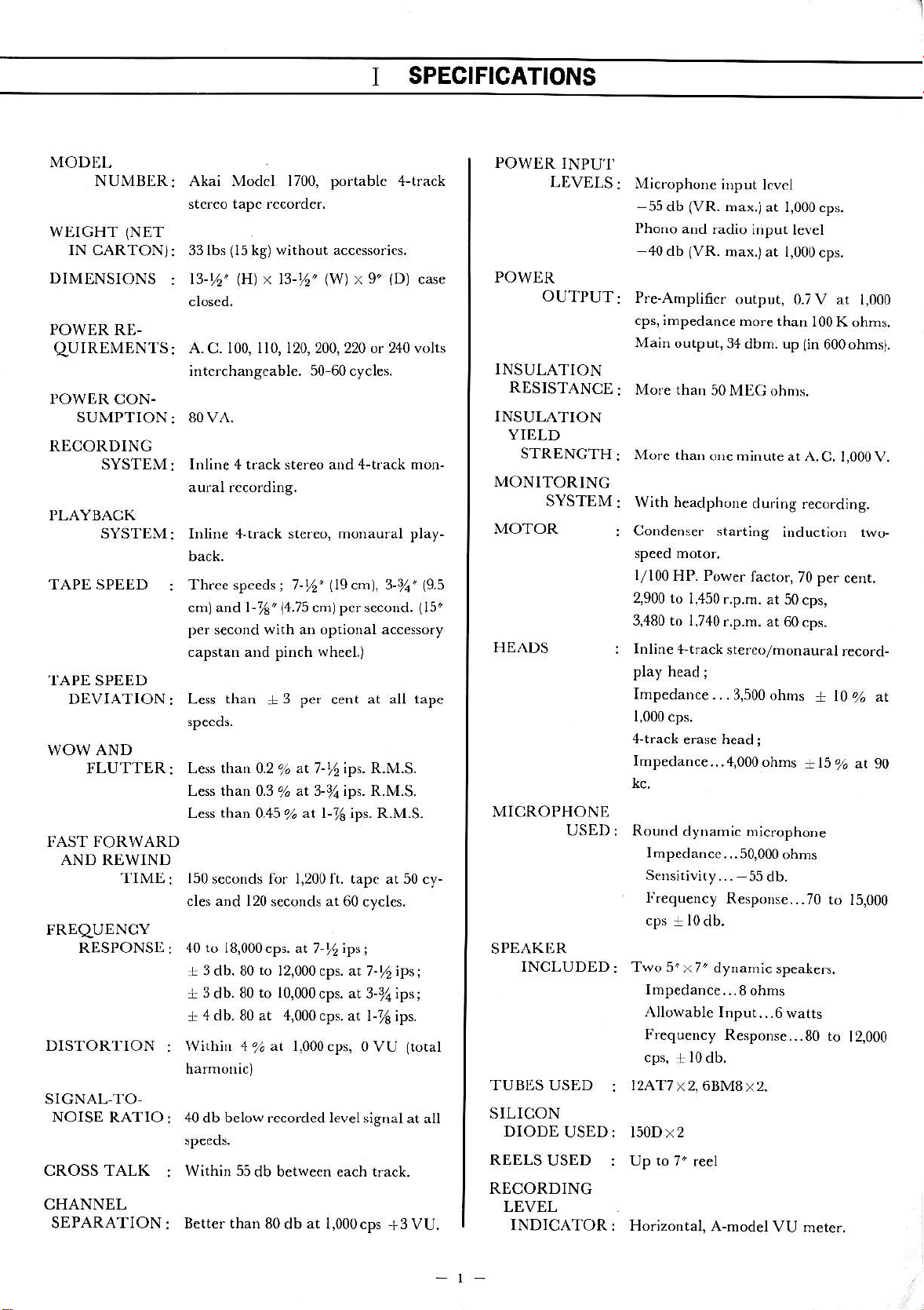
SPECIFICATIONS
MODEL
NUMBER
wtrGHT
(NET
IN CARTON)
DIMENSIONS
POWER RE-
qUIREMENTS
POWER CON.
SUMPTION
RECORDINC
SYSTEM:
PLAYBACK
SYSTEM:
TAPE SPEED
.I'APE
SPEED
DEVIATION
WOW AND
FLUTTER
FAST FORWARD
AND
REWIND
TIME
Akai Modcl 1700, portablc 4-track
st.rco tape rccorder.
(15
33 lbs
t3-t6'
kg) without acccssorics.
x 13-%'
lH)
(w)
x 9'
(Dl
A. C. 100, ll0, 120,200,220 or 240 volts
interchang€abl€. 50 60cycles.
80VA.
Inline 4 t.ack st€reo and 4-tfack mon-
Inlin€ 4.tiack stefeo, monaural play-
Thrce speeds
:
cml and l-%"
p€r
s€cond
capstan and pinch whe€I.)
than + 3
Less
:
Less than 0.2 % at 7-t6 ips. R.M.S.
:
(a.is
cmJ per second.
with an optional accessory
pef cent at all
Less than 0.3 % at 3-7a ips. R.M.S.
Less than 0.45 % at l-16 ips. R.M.S.
150 seconds fof 1,200 ft. tapc at 50
and 120
cles
s€conds at 60 cyclcs.
case
(15"
tape
cy-
POWJ]R
INPU'I'
LDVELS:
POWDR
OUTPUT:
INSULATION
RESISTANCE
INSULATION
YI[,LD
STRENGTH
MONITORINC
SYSTEM
MOTOR
HEADS
MICROPHONE
USED :
Microphone
-55
db
Phono
40 db
Pre-Amplifier
cps, impedanc€
Main output,34dbm.
More than
More
With headphor€
Condenser
l/l00HP.
2,900
to I,450
3,480 to 1,740
lnline +tf ack
play h€ad
Impedance..
I,000
cps.
4-track
Imp€danc€.
Round
Impedance...50,000ohms
S€Dsit;vity...
f.€quency
ir)put lcvcl
(VR.
max.jat
and radio
(VR.
max.)at l,000cps.
output, 0.7V at
50MEC ohns.
than
ore m;nute at A.C.
start;ng
Power
r.p.m. at 50
r.p.m.
stereo/monau.al
;
.3,500
erase head
. .4,000 ohms
dynamic micropho.e
R€rpoDse...70
l,000cps.
input levcl
more than
up
during reco.ding.
induction two-
factor,70
at 60 cps.
ohms + l0
;
55 db.
1,000
l00K
ohms.
(in
600ohmt.
1,000V.
pe.
cent.
cps,
record-
%
+15% at 90
ro 15,000
zt
FRDqUENCY
RDSPONStr
DISTORT'ION
SIGNAL-TO-
NOISE RATIO
CROSS TALK
CHANNEL
SEPARATION
40 to 18,000cps. at 7-%;ps;
.L 3 db.80
+ 3 db. 80
4 db. 80 at 4,000cps.
+
Within 4%at l,000cps,oVU
40 db below rccorded lev€lsignal
Within 55db
Better than
to
12,000 cps. at 7-l,
to 10,000cps.
between each trach.
80 db at l,000cps
at 3-3la;ps;
at l-7s ips.
ipsj
+3
ltotal
at all
VU.
SPEAKOR
INCLUDED:
TUBES USED
SILICON
DIODE
REELS
USED:
USED :
RECORDING
LEVEL
INDICATOR
Two 5'x7'
Imp€dance...8
Allowable IDput...6
Frequency
cps,
l0db.
:!
I2AT7
:
: Horizontal,
x2, 6BM8x2.
l50Dx2
Up to 7'
r€el
A-model
dynahic
R€sponse...8o
speakers.
ohms
warts
VU m€te..
ro
12,000
Page 4
1I
IIOW
NIICNSURE
TO
DESIGNATED
VALUES
SPECIFICATIONS
OF
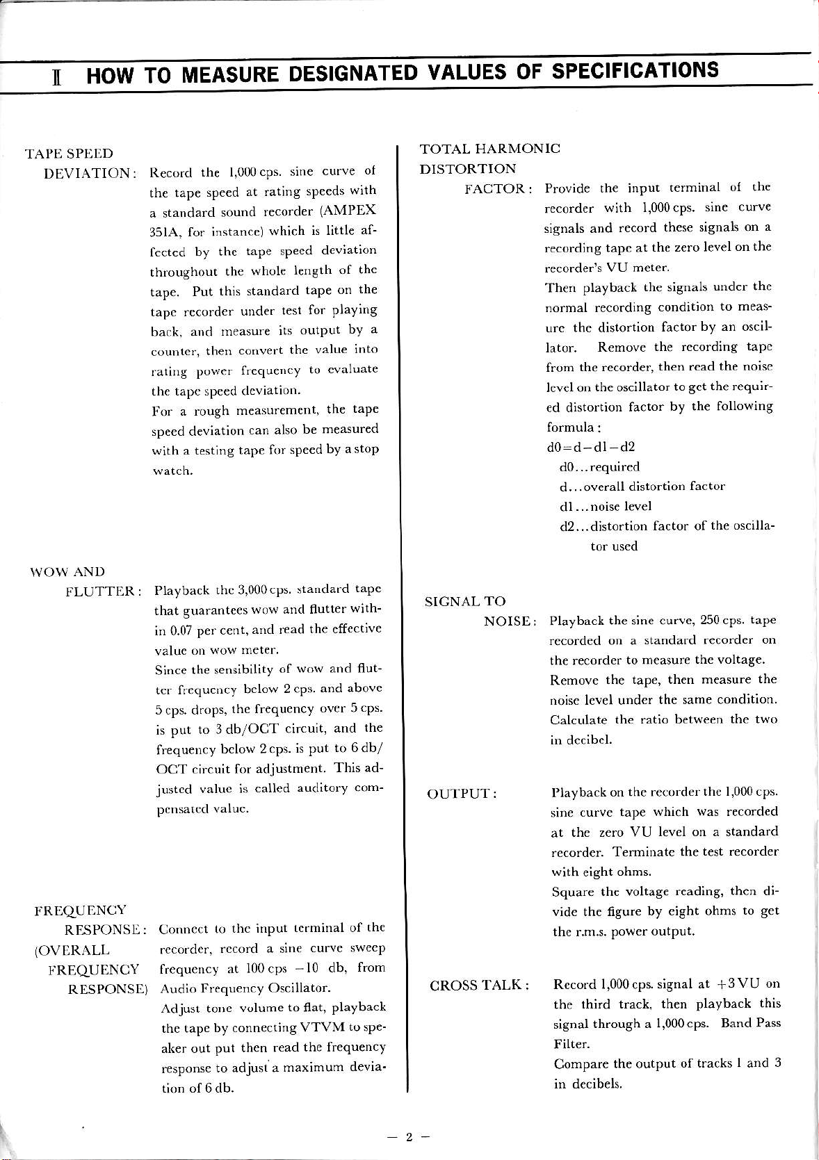
TAI'I] SPDtrD
DEVIATION
Reco.d
:
the tap€
a standa.d
351A,
fccted
tlrroughout
tape.
tapc recorder
back, and
couDte.,
rating
the tape speed dcviatior.
Fo.
spe€d deviation
with a testing
the l,000cps.
speed
sound
for instance)
by lhe
the
th;s standard
Put
unde.
nreasure
codvert
then
power
a rough
frequeDcy
measurement,
tape for
at rating
tape sPecd
can also
recorder
which
whole
test
its
curve
sine
sp€eds
(AMPEX
is little
deviation
i€ngth
thc value
speed by
of the
on
taPe
for playing
outPut
to cvaluate
the
be measured
astop
of
with
af-
th€
bY a
into
taPe
TOTAL HARMONIC
DISTORTION
FACTOR:
Provide
,ecord.r
signals and
recording
recorder's
Then
no.mal recording
u.c the distortion
lator.
from
lcvelon
€d dhtortion
formula:
d0:d-dl d2
the input
with 1.000.ps.
.ecord
tape at
VU mete.
playback
Remove
the recorder,
the oscjllator
d0..required
d...overall
dl...noise
d2...disto.tion
to.
the siSnals
factor
distortion
l€vel
uscd
terminal
':nF ,
these signals on
the zero level
under the
condit;on
factor
the recording
then read the
to
by the following
factor of
to meas-
by an oscil
the requ;r-
8ct
factor
the oscilla-
ol the
urvF
a
on the
tapc
noisc
\{OW
AND
FLUTTER
}.RLqUI]NCY
RESPONSE:
(OVI]RALL
I'REqUENCY
RESPONSE)
Playback
:
that guarante€s
p€r cent,
h 0.07
otr wow
valuc
the sedsibility
Since
tcr frequency
5 cps. d.ops,
is put
frequency
OCT circuit
justed
to 3db/OCT
value is
Connccr
rcco.dcr,
f.equency
Audio
Adjusl toDe
the tape
aL€r out
response
to
frequency Oscillator.
by .onnectidg
put then read
thc 3,000cps
wo\d and flutter
aid read
mere.
of
2cps
bclow
the frequency
circuit,
bclow 2.ps.
for adjustment
called
thc input
.ccord a sine
at 100 cps
volume
to adjusl a
to
maximum
sianda.d
the effect;ve
wow and flut-
is put
auditory com-
tcdninal of
curve swecp
-10
flat,
VTVM
the frequency
tape
with-
and above
over 5cps.
th€
and
to 6db/
This ad-
from
db.
playback
tosp€-
devia'
the
SICNAL
TO
NOISE: Playback
OUTPUT:
CROSS
TALK:
the sine curve,
rccorded on a
th€ reco.der
Removc
noisc level under
Calculate
in d€cibel.
I'layback
curvc tape
sine
the zero VU
at
recorder.
with
€ight
Square
vide the figure
thc r.m.s.
Record 1,000 cps.
the
signal
Filter.
Compare
in decibels.
the voltag€
third tack, then playback
through a
standard recorder
to measur€
the taPe, then measure
the same condition
the ratio between
on the recorder
which
level on a standard
T€rDinatc the
ohms.
rcading, then di
by eight ohms
output.
Powcr
signal at
l,000cps. Band
the output
250 cPS.
the voltag€
thc 1,000 cps.
was
test recorder
of tracks I and
tape
on
the
the two
record€d
to get
+3VU
this
Pass
on
3
2-
Page 5
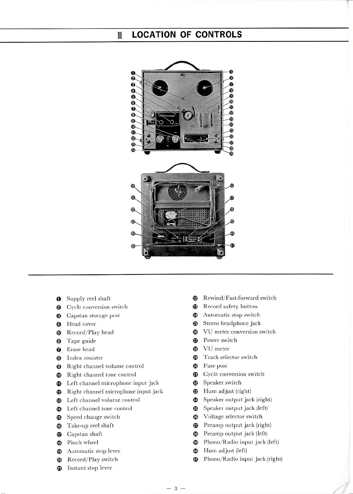
LOCATION OF CONTROLS
I
f
Supply
o
Cyclc
o
Capstan storage
0
@
@
Tape
o
trras€
o
@
Right channel volumc control
o
Right channel
@
Left channcl
o
Right channel
Left channel
@
Left channel
@
Speed
Take-up reel shaft
@
Capstan
(D
Pinch
(D
Automatic stop lever
Record/Play switch
@
rccl shaft
convcrsion switch
post
guide
head
tonc control
microphone
microphone input
volumc cont.ol
tone control
change switch
shaft
wheel
@
input
jack
jack
Rewind/FasFforward switch
Record safety button
Automatic
Stereo headphonejack
VU
@
stop switch
h€ter
conv€rsion switch
@
Track s€lector switch
@
(D
Cycle conversion sw;tch
Hum adjust
(D
Speaker output
Speaker output
Voltage
Preamp output
Preamp output
o
Phono/Radio input
@
Hun
@
Phono/Radio input
o
(right)
jack (righr)
jack
sele.tor switch
jack (right)
jack
(left)
adjust
llert)
{left)
jack (l€ft
jack
(rish0
3
Page 6
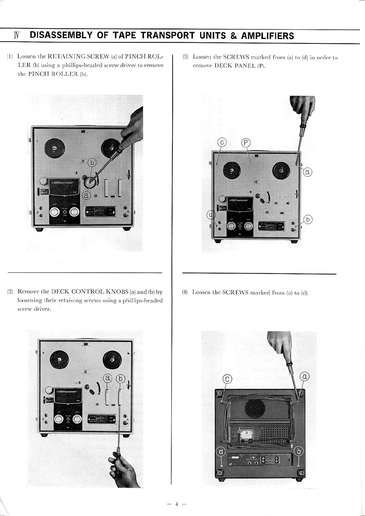
DISASSEMBLY
I\I
OF TAPE TRANSPORT
UNITS
& AMPLIFIERS
ll l-oo!',, rh. lt l:.1.\ I\ lN(;
LI{l , ,lt-'.. ,\vl,v ," !i
ih. l'IN(ill lt()l.l.l lt
SUIlll\f
llil.
I'INCIt R()L-
irlof
L,{iJ.!
13)
r.!!^! l)1'lCK
thc S(lltli\\'S
l).\\l.ll.
nrxrl.(l 1,,,))
tl)1.
r.ri r(j
t{ll
('(1,.r
i,r
ro
l.(.,,,,tr | tlx. I)llUK
12
io,!c,,i,ig d,cif ritx;fing
I
C( )\ l R( )I- ti\( )lls
s.raL. u';i)g
r
I)liillips
o
99
r.t
ialrnd iblby
h.adcd
('11
l.oosci
(h(i
S(iltl:,\\'S,,)rrk.d
f,or)
i.t
r,)
ktr.
I
Page 7
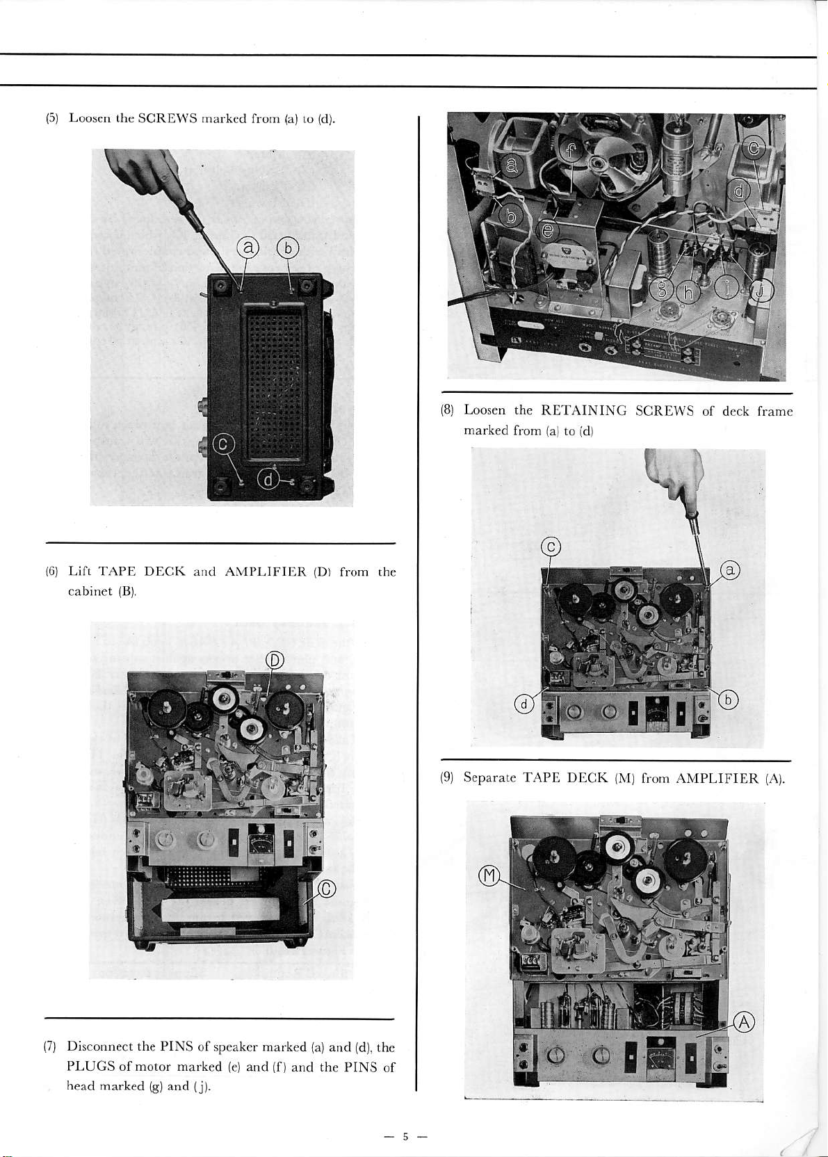
(5)
Loosen
the
SCREWS
narked
from
{a)
to
(d).
(8)
Loosen the
mark€d
RETAINING
(al
from
to
SCRDWS of dcck frame
id)
Lifl TAPE DECK and
cabinet
(B).
AMI'LIFI liR
(Dr
tr"m
,he
(9)
SEPA'AIC
TAPE DtrCK
(M)
frOM AMPLIFIER
(A).
(7)
Disconnect the PINS
PLUGS or motor marked
head
marked
{B)and {j).
of speako marked
(€)
and
(f)
and the
{a)
and
PINS of
(d),
the
Page 8
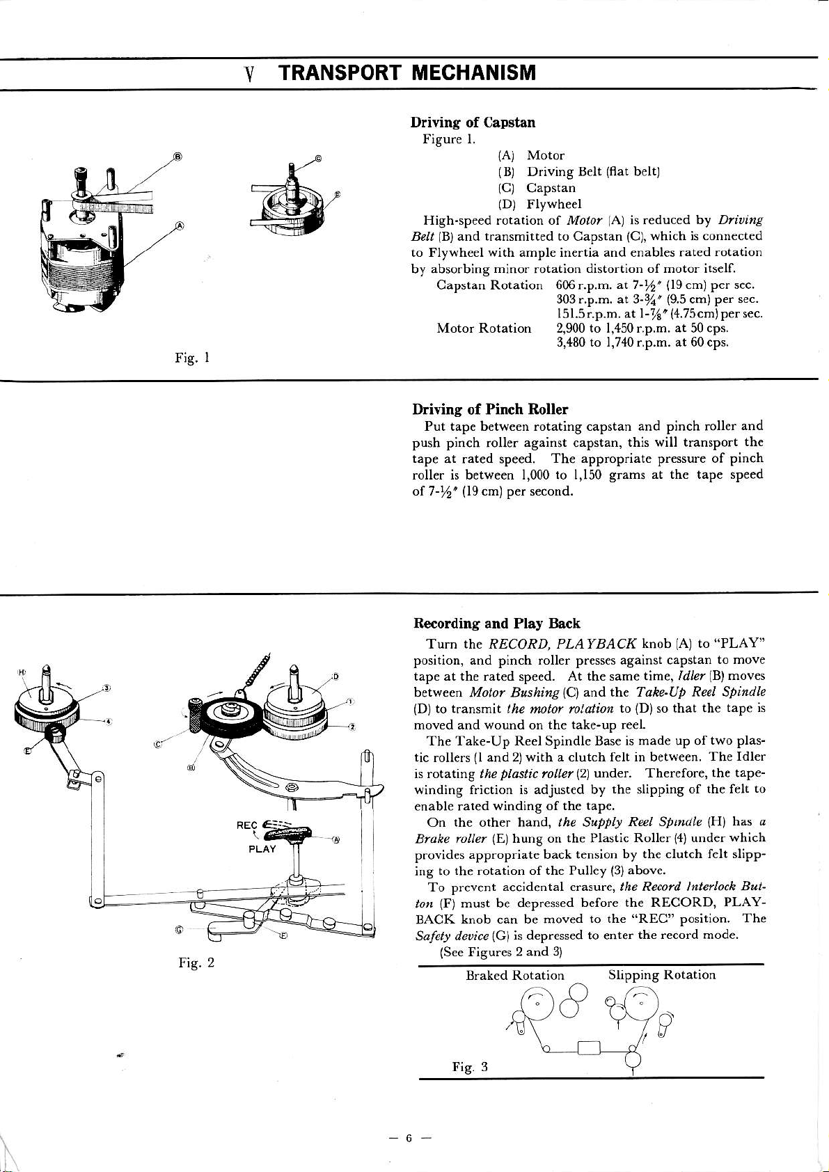
Fig.
TRANSPORT MECHANISM
Y
Driving of Capstan
Fjgure l.
Motor
{Aj
(B)
Driving Belt
(C)
Capstan
(D)
FlYwheel
High-speed rotation of Mot /
(B)
Br,
to Flywheel with ample inertia and €nables rated
by absorbing
and transmitted to Capstan
mino.
rotation
Capstan Rotation 606 r.p.m.
303r.p.m. at 3-%'(9.5 cm)
l5l.5r.p.m, at l
Motor Rotation 2,900 to 1,450 r.p.m. at 50 cps.
3,480 to 1,74{r.p.m. at 60cps.
(flat
belt)
(A)
is reduced by D/trire'
(C),
which is connected
rotaiion
distortion ofDotor itself.
at 7-%'(l9cn)pe. sec.
-16'
(4.7s
per sec.
cmlper sec.
I
Driving of Pinch Roller
Put tape between rotating capstan and pinch roller
push pinch
tape
at rat€d spe€d.
roller is between I,000 to I,150
of 7-%'
(19cm)
against
rouer
per s€cond.
capstan,
this will transport
Th€ appropriate pressure of
grams at the tape sp€ed
and
thc
pinch
Fig. 2
R€coding and Play Back
(A)
TuJ[ rhe RECORD, PLA rB,4Cf
position, and pinch roller presses against capstan
tape at the rated
between
lD)
moved and wound on the take-up re€I.
The Tak€-Up Reel Spindle Base is made up of
tic
is rot^titg the
winding friction is adjust€d by
enabl€ rated
Blake
provides
ing
to,
BACK
Safet! dnice
Motor &tshitag
b rr^ns'lr.it the motol /rldtro,
(l
rollers
on the other ha d, the S*pfb
lo e/
app.opriate back tension by
to the rotation ofthe Pull€y
To prevent
(F)
mut be depressed
knob can be moved
(See
Fisures 2 and
sp€ed.
with a clutch felt in betw€€n.
and 2l
plastic
winding of the tap€.
hwg on the Plastic
lEl
accidental er^sure, the Record lnterloch
lclls
At the same time,
znd t}:'e Tahe-Ut Reel Spindle
ICI
(2)
mUel
depressed to ente.
under. Therefore, the tape-
before the RECORD,
to the
3)
ffi
knob
to
{D)
the
slipping
Reel Sbtndle
Roll€r
the .lutch fet slipp-
(3)above.
"REC"
the record mode
Slipping Rotation
to
Idlel
so that th€
of the felt
under
{4)
position.
"PLAY"
to move
(B)
moves
tape is
two plas-
The ldler
h^s a
IHI
which
But-
PLAY-
The
to
-6-
\
Page 9

FAST-FORWARD MECIIANISM
TurD
lie aASZ FWD-REWIND *no,
5)
(D)
(B)
undcr lhc knob pushes
moves
into
and
lH)
FWD" position, and
the Lerer
the Plast c Rouer
the uppe. part of th. rotating motor drive bushing to
transm;t the motor rotat;on to the takc-up reel spindle. At
the same tihe,
sp;ndle to free
fast
(C).
windnrg
(Sec
ofthe tapc onto thc iakc-up rcel.
ligures 4 and
FreeRolarion Fl;gh-SpeedRotation
ll's ca-
The l.tler
above the Take-Up Reel
lF)
Brale RoUerc
lr, Srrrl! Reel Sti dlelcl,rheteby allowiDT
(A)
to
the
(I)
cone otr the reel
bctween
spacc
Spindle and
"FAST
up
f
Fig.4
Fig. 5
REWIND
"f
utn the FAST FWD-REtl/N,
position, and
up. The
lC)
per part of
MECHANISM
the cam
ldlerlDl
the
lB)
noves
rcIating Motar
Interned ate Pulle,lF) to hansmit
o
izo,
u^det $e k\ob ptshes
into thc space
dtue bushing
the high-speed
of themotor through the interm€diate
Reet
Spindte
come ofl
the
ther€by rewinding the tape
(See
F;surcs
At the
lC).
sahe time, Brale
re€l spindle b tree the
into rhe supply reel
6 and 7)
take-at leel spindte
High'Speed Rotation
'J
Fig. 7
(A)ro
"REWIND"
betwecn the
pulley to
Roll€ls
YO
o
the Leuer
and
lE)
rotation
tr? Srrrll
(H)
and
ar a fast
up-
the
(I)
lJl,
(a)
sToP
(b) FAST-FORWARD
(.)
REWIND
Id) RECORDING
NOTES :
-marks
x
O-ma.ks
o
o o
indicates
"engaged"
o o
"open"
and
o o
STOP
{A)
sp;ndles.
the .eel spindles, no triction works
7
CONTROL
Push ihc
and
As thc brake rubb€r depfesses the
Supply R*l
stop lever to
depres reel spindles to stop .otation
1B)
Spindle
R*ind
"STOP"
ldle$heel
fig. 8
positlon,
on the tape its€lf.
Take-up Reel Spindle
Bruke Ro els
of the reel
plastic rolleG under
('
Page 10
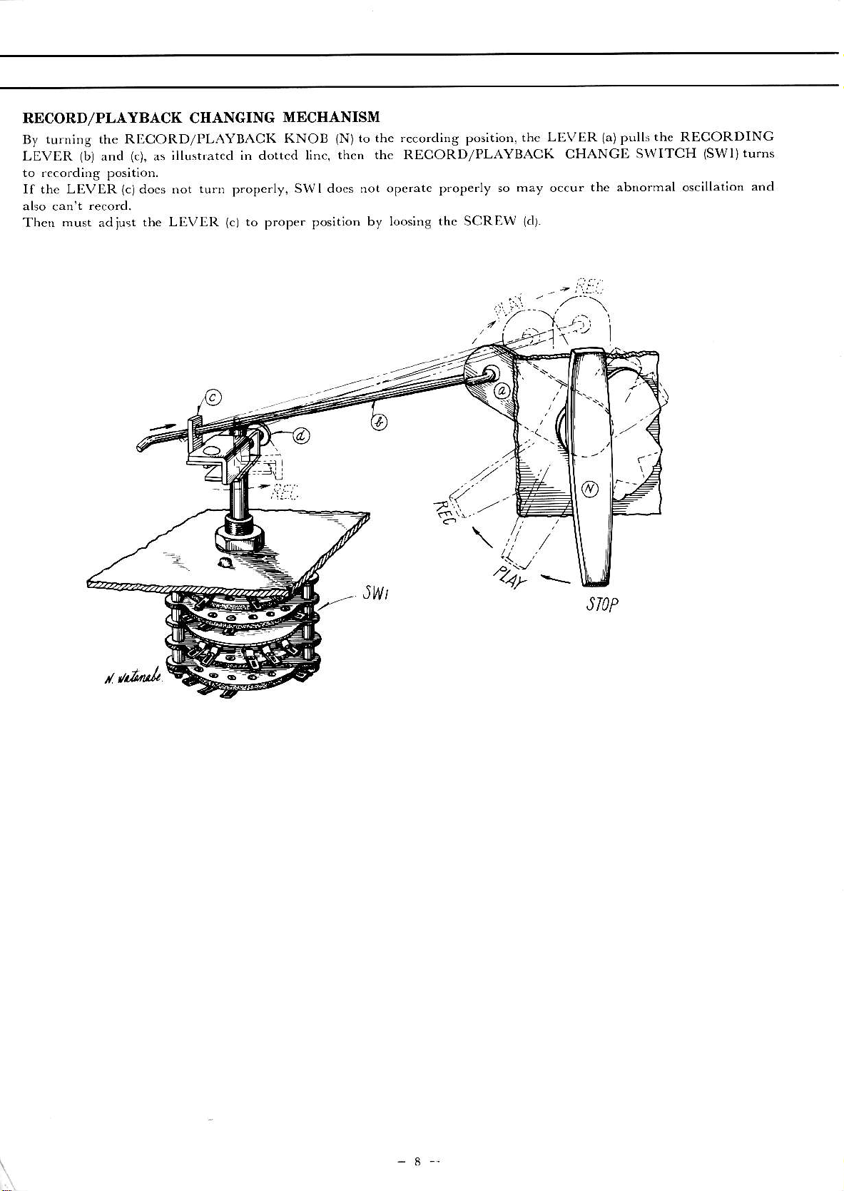
RDCORD/PLAYBACK CIIANGING
turning the RLCORD/PLAYBACK
By
LEVER
to .ecording position.
If the LIVER
(bi
and
(c),
as
(c)do.s
;llushated in dotted l;nc,
not turn
propc.ly.
MECHANISM
KNOB
(N)to
then the RECORD/PLAYBACK
SWI docs not operatc
recording position, thr
the
LEVIiR
CHANGD SWITCH
prope.ly so may occu.
1a)pulls
the abnormal oscillation
the RECORDING
(SWl)turns
and
Then
must
adjust
the LI.VIR
(cl
to proper position
by loos;ng thc SCREW
.
r il.',
Itz__\,/..r',
'l-a1'1';':
.'/...
(//
,,-^:,..
,/
\l/
..)._u.
.
,4)"
JWt
lcll.
-
,z--\
,
/
_
Page 11
r
ADJUSTMENT
U
1. ADJUSTMENT OF
It is imporlant that the piich
complcte alignmentwith
pressur€
wheel
unit is ope.ated
from this specificalion
tion
Check
r,ecesar
I'in.h
y.
is bctween
at the tapc spccd of7-t6
wheel pre"su,. bv r
ju"r
rhe pin, h
ad
2, ADJUSTMENT OF
take-up ;dlm wheel
The
ment ltith thc takc-up reel shaft.
fast forward condition,
upper knu.led
will
and it
play modc. Adjust idlerwhccl
or
wheel pressurc is kept between 50
idler
qh..l
;dler
The slippage occurs
wheel
contact
rapidlv
to thc lower kn urled
:ir".
..t,
PINCII
the capstan shaft.
1.000 and I,150 grahs
will result in wow and
whpFl
TAKE.UP IDLER WHEEL
must
be
thc idler
the takc-up reel shaft
of
wear.
:f Ihf pre*u,.
if thc prcssu.e
=..".".,..
;
ll
Fig.
12
Fig.
WIIEEL
wheel shaft i5
A properpinch
ips. Any devia'
.1-.ring
load 5t.inB.
kcpt in complete align-
Whcn the unit
whe€l will contact to the
whccl du.ing record
load spr;ngsoihatlhc
and 80 grams.
is smallef thaD the
R(/.Ly Hli
kept nr
whcn the
'cale
assembly.
Px,.ssi\c.
b
flutter.
at.d.
is set in
The
OF TAPE
3. ADJUSTMENT
The .c\rind
mcnt with thc rewi.d
to the k,,urlcd
50 gfams during rewidd ope.ation. Adjust both thc idler
load spriog aDd
if
4. ADJUSTMENT
Thc
whccl
idler
part
of
sct in rewind mode, it will
taneously deliverins torque of
su.cis50grams. Adjust thc load sp.;ngofthc inrermed;ate
wheel if the
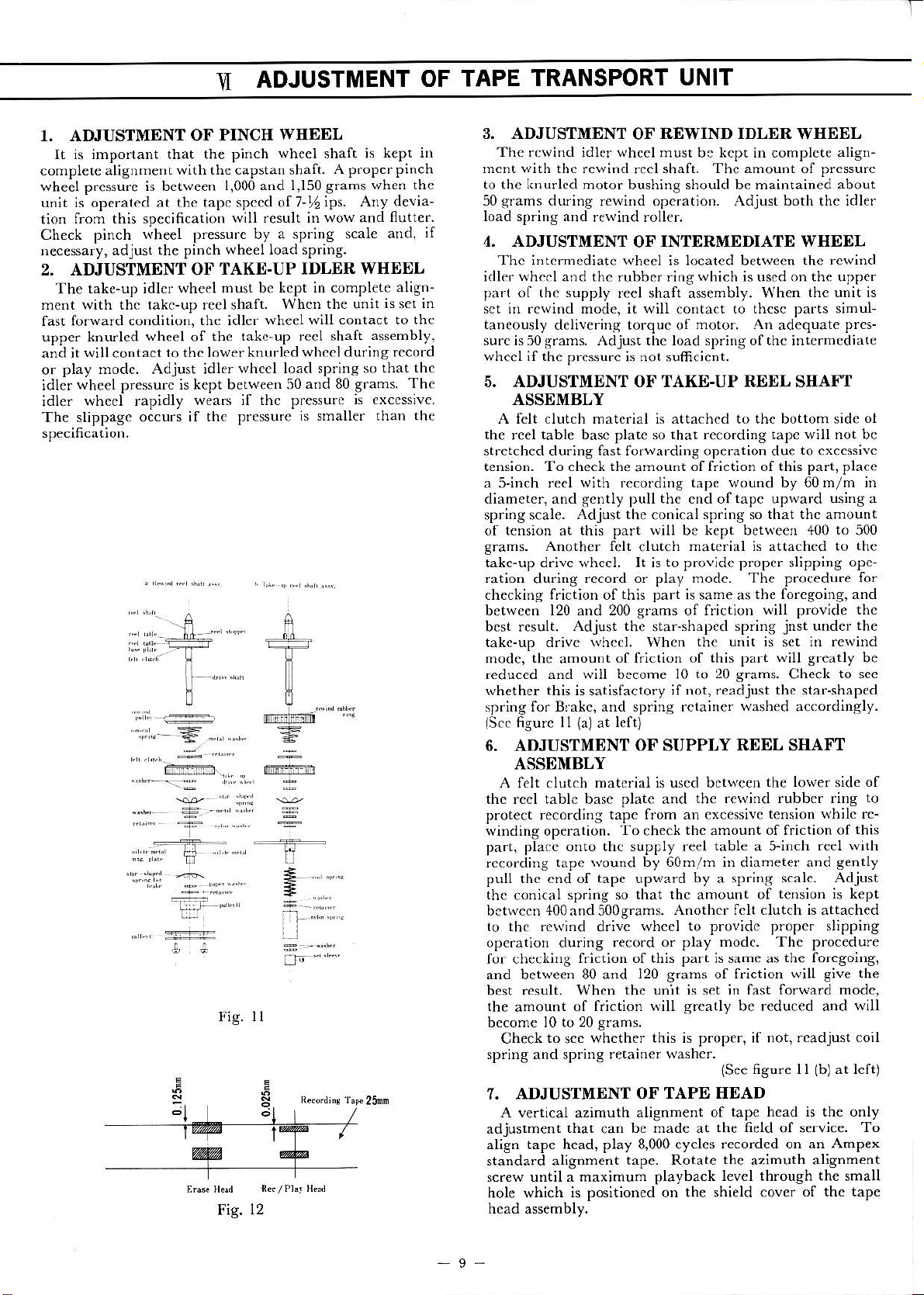
5. ADJUSTMENT OF TAKE-UP REEL SIIAI'T
ASSEMBLY
A felt clutch mat.rial is attachcd to the bottom sid€
the
reel
stretched during lhst forwafding operation due
tension. To check the
a S'inch reel
diameter, and gently pull the cnd of tapc upwarcl
spring scale.
of tension at this part will bc kept between
grams. Anoth€r felt
takc-up drive wheel. It is to pfovide proper slipping
ration
checkins friction of
between 120 and 200 grams of frictioD
best result.
takc-up dr;ve
mode,
reduced and \viil become I0
rvhether this is satisfactory ;f iot,
spring
fisure
lscc
6. ADJUSTMENT
ASSDMBLY
A felt clutch
thc reel table base plate and
protect reco.ding
winding operation.
pa.t, place onto thc supply reel
rcco.ding
pulL thc cnd of tape upward by a spring
thc
conical sp.ing so
bctwecn 400and500grams.
to thc re\v;nd
ope.atioD cluring
for checkn)g
and betwe€n 80 and
result. Whcn
best
the
amount
become l0 to 20
Check
spring and spring r€tainer
7. ADJUSTMENT
A
vertical azimuth
adjustment
align tape head, play 8,000 cycles
standard alignment
sc.ew
hole which
head assembly.
TRANSPORT
OF
whccl
idler
motor bushing should be maintained
rewind roller.
OF
intcrnediatc
and thc rubbe. ring vhich is uscd on the uppe.
the supply
pressure is not sufrc;ent.
table
du.ing
Adjust the
the
amou.t
fo. Bfakc, and spring rctainef
ll
wheel
reel shaft assembly. When
basc plat€ so
with
fecordins
Adjust the
record or play modc. The procedu.e
this part
whcel.
of f.iction of this part
(al
lefo
at
UNIT
REWIND IDLER
must be kcpt in complete
shaft. The amount
reel
INTERMEDIATE WHEDL
is located between the
contact
that reco.ding tapc w;ll not bc
amoudt
conical
clutch
star-shapcd
lvhen
to thcsc parts sihul-
motor. An
of friction of this part, plac€
tape wound by 60m/m in
sp.ing so that thc amount
matoial ;s
; same as
spring
the unit is
to 20 grams.
readjust the star-shaped
washed
WSEEL
adequate
attached
the foregoing, and
will provide the
jnst
set
will greatly
Check
accordingly.
OF SUPPLY REEL SIIAFT
matoial is uscd between
the .ewind rubbcr ring
tape from an excesive
To
tape wound by 60m/m in diameter and
that thc amount of
drive
reco.d or play mod.. The procedure
friction of this part is same as
120
the
of f.;ction will greatly be reduced and
grans.
to
whether this is proper, if not,
sce
thc
check
wheel to provide
unit
amount
table
Anothc. fclt clutch is attached
of friction will give
s.ams
js
set
washc..
the love.
tension \th;le re-
offriction of
a 5-inch
scale. Adjust
tens;on ;s kept
proper
the
;n fasi forward modc,
rcadjust coil
figure I I
{See
OF TAPE HEAD
alignment of
that
until a maximum
is positioned on the shield cover
be made at
can
tape. Rotate
playback level through the small
tape head is the only
the field
recordcd on an AmP€x
th€
of service.
azimuth al;gnment
align-
pressurc
of
about
rewind
the unit is
pres-
to
excesivc
using a
400 to
in rewind
of the tape
500
the
to
opc-
for
the
under
be
to scc
side
this
rcel with
gently
sl;pping
foregoing,
(b)
the
will
at left)
To
ol
of
to
-9-
Page 12

ADJUSTMENT
tll
AMPLIFIER
OF
r. ADJUSTMENT OF RECORDING BIAS FREQUENCY
Rccording/crasing bias frcquctrcy
otthc oscillato. coit
l0
or
the
100
ohm
13. ADothcr testirg
Fig.
a
in
cted to hor;zontal input terminals .,f the oscilloscope. Vary frequcncy gene.ated
90 KC, and set the oscillator at the point whe.r a desirous 6gurc appears on the
no$' corrcsponds to the reading of the oscillator. Check oscillator coil, C-17
mcasu.ed ; not w;thin 90 KC + 5 KC.
lpart *
resisto. ;n
l7-L,)
scrics
2, ADJUSTMENT OF RDCORDING BIAS VOLTAGE
A p.oper rccordnrg bias vottagc is 45 volts + 3 volts A.C.
and is adjusted
coDD€ct a V.T.V.M.
head
/play
Check Cl6
recording bias voltage
mentioned specificatioD.
by
as showD
(included
To measure .eco.ding bias voltage,
Cl6.
(Vacuum
;r the lig. 14.
AKl3)
mcasu.ed
was
set at 90 KC plus or m;nus 5 KC
its resonant
and
to the .cco.d/play head
instrument
Tube Volt Mete.) to the record
and
does
to
record/play head if the
not meet to th€
capac;tor
and coDnect vertical ;dput te.minals
be prepared is an audio frcquency
abovc-
before sh;pment. It is
(part
C-17). To mcasu.e recordiDg
f
oscilloscopc.
and bias head if the recording
oscillator and
tbe
by
audio frequency
'fhc
decided by inductance
bias frcquency, insert
of an oscillos.ope
jtsoutput
recordins bias
shouid
oscillator around
bias frcqucncy
i f^-
o;.---r:@*=;;'6d.".0,.-""
Fig. 13
as showq
be conDe-
frequcncy
L1{0,s.c)
3. ADJUSTMENT OF
A prope.
a V.'[.V.M.
Chcck Cl4 and crasc head il thc oasing bias voltage measured
€rasing bias
to the
ERASING BIAS
voltagc is 65 volts
head
erase
as rhown
VOLTACE
+ 5 volts
in the Fig. 15.
A.C.
and is adjusted by Cl4.
-I
li'
j(PllLEFT]
Hi|mn-!,(c,lEIcHr)
I#ltlri!i
To
not meet to the
does
#;;;-v'1c'
I;':I:::j-:-
lRrcHr)
v
l1
LE FT
1i,l
'
v,(P)(RrcHT)
F;g. 14
neasure erasing bias voltage, connect
above,mentioned spe€ification.
)
Fig. 15
ADJUSTMENT
4.
A
current of
The VU neter indicates oVU ! 2 VU wheD a signal of
at the microphone
thc volumc control set at its maximum.
Adjustment ot recording level can be accomplishcd by varying
tivity of VU metft, however, it is not necesa.y to make in a field
service as all VU
shipment.
NOTEi Make sure to stop oscillation by disconnecting the oscillator
rccording lcvcl, .cfefcd to
basic
30lA + l0 % flows to the recording head
mete6 have co..ectly been calibrated at
(See
lig. l6
coil | 17-L, at the points marked
ment
reco.ding lcvct.
of
RECORDING LEVEL
OF
jack
-40db
or
for details.)
+
as
"oVU",
5db at the line input
and
"P"
th€ point
s€t at
at
-55
factory befor€
prior to measure,
"G"
where
1,000 cycl€s.
db + 5 db
jack
when
sensi-
of
o-, ^
-,nrl
ll,,n
r
r"
Fig. t6
Page 13

.UN
1. LUBRICATIONINSTRUCTION
For maximum senice life and optimum
ope.ation. Use only
Motor
Drive Capstan
Rewind Idler Wheel
Intermediate Idler Bearing
Pinch Wheel Bearing
Take-up and Supply Reel Shaft Bearing &
Also apply
light machine oil of
Shaft
Bearing and wind take-up Idler Bearing. I drop
a liberal frlm oflight machine
MAINTENANCE PROCEDURES
performance, lubricate
good quality
grease to
the
each roller surface of
parts
id€ntified
below after each 500
3
drops
2 drops
I clrop
2 drops
2 drops
all levers and cams.
hours of
CAUTION: DO
SOAKED IN ALCOHOL.
BE SCATTERI,D
WILL BE DETERIORATED.
NOT
OVER-LUBRICATE.
DURING
WIPE OFF EXCESS OIL BY A COTTON SWAB
O'THERWISE, THE OVER.FLOWED LUBRICANT MAY
OPERATION,
'
tt.6
THE RUBBER COMPONENT PARTS
r.-'-'''
r
17
Fig.
2. CLEANING
Wipe surface of
in alcohol or carbon-tet.
TAPE HEADS AND OTHER PARTS
tap€
FLYWHEEL
guide roller bearing, capstan
h€ads,
MOTOR
bushing and pinch wheel periodically with a soft
It
cloth
soaked
Page 14

r7r-0ot
002
003
00.1a
005a
005c
TOP PAl{Et
Capstan Holder
'rablc
Table. Washel
A,
'Iapc
Guide
il
IIST
172-0O{t
001u Pulley,
001v
005
0o5,
00,b
m5c
005d
005f
005e
005h
oo-i
REPTACEMENT PARTS
OF
Washe. }in
Reel Shalr
Screw, without
]?Le-up R€el A$embly
Reel
Shaft
Felt Washcr
T,ke-up
Spfing G, Risht
Takr-up Rolle., B
Holder, Reel Shaf.
Typr spring)
(Sta.
Metal Fitlins
sPrirs,
He"d
A, Tat€-up Reel
Rouer, A
B. RceL
F3
_rnbL
ParB No. Nomenclalufe
172-012b
Plare. Automaric Shut of
0l2c Scr€w Sen,i-Cubi. 3x5
013, Mirtu Swirch M-8-3
0l3b Holdef, Switch
0l3c Screlv Semi-Cubic 3x5
0l3d Sc.ew IIat Mould 3xl5
0l4a
SNirh. Speed Change
pP slide swnch Nc)
0l4b Plate, Speed Change Switch
0l4c S.rew Flar Mould
0l4d Co.d
Supp.rt
.1x
10
005e Bcaring (635JZZ)
0059
Table, Washer
00si
Table D, Tape Guid€
005j lrop, Tape Guide
DECK FNA
172 001
Deck Fradc
002
H.ad A*embly, Conplctc
m2a
E.ase Head
m2b
Record/PlaybackHead
002c
Scfew Flat Mould 4r8
002d
Prop A, Head
002e
Prop C, Hcad
002f
S..c\Y l.-lat Mould 4xg
002g
S..ew Fhr
003
Index
Counier, Complete
0I)3a Pulley,
003b
003c
00+
00{2
001b Plate,
00rc Reel
004e
m4f
m{h Washer Pin, La.se
0O4j
004k
0040 Waiher
@4q
0O{r
Counte.
Belt, Counrcr
SGes, Wnhour H€ad 1x7.5
Supply Reel ^$embly
Sc.cv l_lnt
Reel Tabl.
Shaft A,
Rewind Pulley
Sp.ins
G, Left
r-ak€-up Rouer,
Holdef,
(Sta.
Metal Fiting,\, Reel
golde.,
lslar
Reel Snaf.
Typ. Sprins)
Pin.
Reel Shalt
Type Spring)
I
,1x
I
3xb
Supply Reel
C
large
Table
O05l
Washer
005n
Nylon Spring
006a
AS Levcr, Conplete
006b
Plate, AS Levcr, viih AS
Lever
006c
Screw Bind 3x5
006d
Wash€r Pin
dl6€
3 mn eround Lug
007a
Instanr Stop Lever,
007b
Spring. In$ant Stop Lever
{]07c
Stopper, ln*ant Stop Lever
007d
Screw Bind 3x5
007e
Hold€r B, Innant
007f Screw Flar
O08a
Recording Safety Bu(on
008b
Cah Sroppe.
008.
Fibe., C,n Sroppe.
000d
r.sulator Plate, Can Stopptr
008e
screw Fhr
009a
Pinch Wheel
009b
Metal Cap, tinch Wheel
009d
Lev€r, Pinch Whccl
009e
Shaft C, Pinch Wh.€l
009f
4mm
0099
Shaft A, Cam Roller
009h
C2m
mgi
shafr. Pinch wheel
0l0a
0l0b
Take-up B.ake Roler
0l0c
Screw, B.ake Roller
0l0d
3 nm Nur
0l0e
010f
olla
Levcr, Supply B.ake
olrb
Supply
ollc
olld
3mm Nur
0l1e
shafr, supply B.aLe L."..
ollf
Washer Pin
0l2a
(6P
Pin
ProP
Mould 4xB
Mould 4x8
Nut
Roller B
Lever, Take up Brake
sbafr, Takc-up Bralc Lcvcr
Washef
Screw,
Swnch, Autonatic Shur-of
Pin
Brake Roller
Brake
slide sritch)
Stop
Roller
]\
Lcvcr
Levc.
olsa Idler Whe.l
0l5c Walher Pin
0l6a
Internal Wheel
0l6c
Washer Pin
0l7b
Shaft, Lcv.r A
0l8b Cam Rolle., A
018.
0l8d
0l9b
021 Lcvc., D,2
022b Can Rollcr, A
023b Holdc., L.ve. G Meral
023c
023d
02lb
026a Lev€r F, lor
Roll€r, B
Cam
Washer
Washe.
Sropper,
Lever G
Idler Shaft,
Pin
Pin
Levcr G
Metal
B
Motor
027
028
029
Hun Buchins Coil, f6r
Left
12
Page 15

172,030b Hunr
Holder, Hh Bucking Coil
030c
Screw
030d
B!.kins Coil. fo. Righr
Scmi-Cubic 3x22
Patu
No. Nonenclaturr
00le 8mm Ball Bearing
001| S$itch Table, A
17-C2
c3
o4
Mica Condense. 10U 500 Wv
Ceranic
CeEnic
Condenser 0-02 P
Condcnscr 0.02 P
Lever, Belt Change
032a
Metal Fitting.
032b
Sp.ing, Belr Ch.nge Lever
032c
Table. Lifter Pin
033a
Sporh, fo. Lilte.
033c
Can A, Hcad Lilter
033d
033e C,n
034b
034c
034d
034e
034f
0349
034h Sp.ins, B
031i
034j
173-001 Motor,Conrplere
00la
00lb Stepped Puuey
00lc Belt Holder
00ld
00le
oolf
00lh Moror Fan, D
00li MP Condcnser 2ul
mlj dolde., Moto. Condense.
mlk Prop, Motof
00ll
00lo S.rcw l.-lat Mould 4x50
00lp S..cv, virhout Head 4xs
00lq
00lr Hexasonal
17.1-001 Flywhe.l,Cobplcte
00lb Main Mctal C,se
00ld 4 n,m Ball Beains
00le Pl2te C, l.-lyrvheel
00lh Wing Nut
00li Sc.eN, llywhkl adju$
00lj Prop B, Flyvhc.l
001k lrop C, Flyrvheel
00ll Drivc Belt
175-0ol Svn{:h
00la Knob, Record/Playba.k &
B, Head Liftef
Sp.ing, UN-D
Spring. D
Spring. D
Spring, Idle.
Nerv Spring D
To.sion
Spring, Beh Change
Sp.nrg B, Belt Change
s..e\v
Motor
Oil R€tain€r
Motor Hold€r
Prop, Motor 0 x 21,5
Sc.cw Bind 3xs
Rewind lat Fo.wa.d
Belt
Spfins
Fla! Mauld 3x 15
Pulley
8x22.5
Nut
Block
change
(260vACl
Fai/Fonvard Rewind Shaft
00lb
Rcr'Playba.L Resind Shaf.
00li
Pin
00lj
Plate. Cam
00lk
Sp.ing, K
00ll
00ln SRitch
00lo Record/llayb2.k
00lp Spo.k Cam
mls Screw Bind 3x5
Ttble, B
Conv€.sion
cAst
176-001
A2
l7-AKl3 C.R. Compound Bodt
AKl4 C,R. Compoud Body
C26inrt,Complcte
002a Table,
002b Rubber Foot
002c Screw Semicubic 3x l8
003a Ventilator
003b
0Or2 ventilaror, A
00,1b
005a Ventilator,
005b Screw
Rubber loot
(Panel
S..cN T.us 6t 12
S-ew Tru$ 6v 12
B
Tru$
{ix
12
Escucheon)
006
007
00Aa Chasn A. Spealie.
008b Chash B, Speale.
009a Speaker
009b Sct\r
5x
7'i
Flat Mould 4x12
AitPUFttR
Ampli6er
Ampliner Knob, B
nsl€.
Sc.ew, rvithour Head 4x6.s
S..€iv, ivithout Head
Scrcw,
Knob, .\
changing Voltage
Semi-Cubi. 4xo
(Tone)
(Volume)
4x ll.5
c5
c6
c7
ca
c9
ct0
cll
ct2
cl4
cl6
cl8
C20a b
c2l
c22
c23
c24
l?-Rl liied Resisror
R2 lixed R€sistor
R3
R4
R5
R6 Fixed
R7
RB
R9
Rlo
Rll
Rl2 Fixed Resistor l,/,IP
Rl3
Rl4
Rl5
Rl6
Rl8 Wned
Rlg Wired
Rro lixed Resistor lL
R2l
R22 Flexible
R23 Fixed
R24 Fired
l7-vRl-2
VR3 Wi.cd
VR4 Wired
Oil Paper Condenser 0.05
Cerani. Condenser 0.02P
Ceramic
Ceramic Co.densef 0.02
Ce.anic Cond.nse. 0.02P
Ce.ani.
Ceramic Condenser 0.02
Tubular Type Elecr.olyric
Condense.
Mica Cond.nstr lou 5m WV
Mica
Mica Condensef 500J 500 WV
Lug Te.minal Type Eleclrolytic
condens.r 40+40
Tubular
Condenser
Tubula Type
Condenser 20/r 300 Wv
Tubular Type Eleclfolytic
Condenser I0rrf 15 WV
Tlbula.
Condensef
Fixed Relkrdr
liaed Resistof l/21'250KO
Fixed Resntor l/'2P l00KO
Fixed
[ixed
lixed Resntor l,'4P 20KO
Filed R€sinor l/4 P I MQ
Flexible Reshtor I W 8(}
liaed Reshtof l,/4P loKQ
lrixed Resntor l,/4P 500K0
Fixed Resnio. l/'.}P 500KO
Fixed Resisto. l/4 P I KO
wned R€sisror 3WL 180Q
Variable Reshtor I
soK(A) Double VR
100{I
1000
Condens€r 0.01 P
Condenser 0.002 P
s0
Af
Cond€nser lsu s00 WV
Type El.ctrolytic
,l0
rl
Ttpe Electrolytic
l0rf I0
Rosisror l,/4P 2KQ
ResGtor l,/2P 250KQ
Reshtor
Rcsisto. 10WL
Resisto. loWL 4700
wi.ed Resistor 3W 8f)
Resisto. l/4P loKQ
Reshto. I/.1P 5000
Vari"ble Resntor l/2W
variable Resisiof l/2w
M
P
P
25 WV
350 wv
llf
350 wV
Iilectrolyti.
WV
l/.lP 500KO
I/lP 3LQ
l//4P ,.2M{}
l/4P 500KO
2000
.t70Q
loKO
M(Al
l3
Page 16

Paf6^"ol7-SDl Sill.onc
sD2 silicone
\on,cn.lalu'c
rT tt
t2
l7Jr
J2
J3-5
(lonne.tiv.
2
2 Conne.rive
2 Connecrn(
J4
J6
l7
17-ll
\'2
r,r
l7
1,2
l7,Ml
I)nxlc sM-150D
I)io(le
SNl-150D
Pin
Jack
}n,
Jack
Pin
Ja.k
Pafts No. No.ren.latu.L
l7-S\!2
SW:l
Sw4
S$5
5\46
lT llll
TB2
TB3 4lL2
TB1
TB3
6P Sl'(lc S\nch. rvth \lhiic
Knob
6l' Sli.le S\rinh.
Krob ispealef
8P
l-osglc
oN,
6P Slnlc
Knob
52L2 Lug Pl.t.
,12L1
311-1
2Ll Lus
vr(uur,
va.uun, Tube l2^T7
rcr Conve^ion)
li\fu
e S\vir.h
Sl
S\ir(n
oFrrl
Svirln. \vnh Black
60,y(lr
1t0
Lug }lare
l,ug Platt
Lus Platc
l'hrr
'l\lbe
vith Wbitc
ON OFr'l
(l-'r{:k
iPo\fcr
12'\T7
Lhangt)
P,.6 No, Nonren.Lrtufe
l7-\rs3 V..uun
Drulrl typr
VS4 Vacuun
n,orkl
l7-Zl lran\formcr Angle,
,42 lransforner Angle. Rishi
z3 Namc Plate. Cycle
2.1
25 He\rsonal l.o!, Selector
26 Nade
27 3 nnn \ut,
Z8 Clord Support
Z9 Rubb.r Bush,
7rr lhrc '\,
Zl2
So.krt,
Phtc B,
Cla.ip
Clanrp
'Iube
Socket, 9P
Tubc So(kd. 9P
(yPc
change Voltage
Plrtc, Lhangc ,\Cl
spo.irl
AC Coftl
Ja.k
Jack
Pin, nr. 6BQ5
Pi., fo. I2AI7
Left
Changc
l7,tl-l lilot
lL2
l7 Swl
l-amp
Rota.y S\rirch
rlayba.k Co.verion)
Lanp
So.kri,
Front
S$ad Type
(Ro.orll
17 \'sl
VS2
T EXPLODED
Ponel
Vacuum Trbc So.k.t, 9P
moutr lype
vr.uun Tube
rYP.
nnrnld
VIEW OF
I7t
00t
So.kcr. 9P
COMPONENT
Zllr SL.dv ScdriCubi.
Zl lb Screrv SenriCubr
zl4c S.r$v Flat
Zl4d
S.rc\L S.nri Cubi. 3r
Mould
PARTS
lra
:l:6
,1:
lt)
6
-0
I7t
171-0
-006
r
Page 17

Amp
I76
176
17 213
lif ier
008a
0l
I
I76
009a
17
A5
I76 0c8ll
nl0
I76
17 Z.
17\t2
17
213
I7-SW,
17- J.
17-J,
Amplif
176 010
I76-008a
ier
II
]7.SW,
r7
Jl
176_009a
]7.VS,
17
Z.
1-7-214.
17 Z1+a
i76-0t0
17-J
t7-2,,
I7-Sy/
17
17 Z,
t7
17 T
176
Z7
z
010
7SW
17-
17.)
r 7 S!!,
17 J
008b
176
11'Z I a
I7VS,
t76 010
r
t7
-y26
Page 18

i=
1l
d
cr
:€
e
fF+
(I
=
o,
;
t
=
r=
,\-a
1b,
Page 19

176-O0l
r
76'006
Cqse
I
176
Cose
007
II
Case
llt
176-002a
Page 20

i\,rr-ooo^,.--4
112 0A4b
172'OO5a
172-AO4c
172-OO4d
172-005b!-
-172
OO4e
112
172-004f
1 /2-AA5d
172-OA4h
172-OO5e
172-O05f
172-AA4i
72-0a4J
172-OA5
172-OO4k
172-OO4l
172'OO4n
172-O05i
172-OO5k
172-OA5l
172-OObn
,{.fu
Page 21

N
Eo
5F
N$
N
N
N
T
\
I
l'-
N l'-
I
F.
l'-
8
l'-
.m
8
-rlE:
FqR:
l'-
l.-
-
,**Fq
F.
R
t-
-19-
Page 22

99
R
N
s
N
l_==
N
C
3e
tU
a-i-:--r€L
>iso
I
e
0
o-
0s
_\_
---+J=l-!H
0
;a
o
g
O
\;-A----
N
I
l'-
I
I
e
N
N
-fttitt::itt_-
N
N
Page 23

-c
I
0
;7
o0
0
F.
f-
@
Page 24

:
E
t^
rqr-
l'-
?P
N
?
N
-20-
Page 25

5
:
e
a
a
o
o
Lrl
6
o
E
G
o
l!
e,
E
(,
(,
z
E
E4
P
;-
e
s
d
a
c
E
a
R
:
t
c
g
d
€
!
:
R
e
E
3
p
s
3
:
I
I
:
€
3
c
E
!
c
o
o
E
att
LII
o
f
0
E
-I
=
e
CE
o
CJ
I
I
o
o
A
o
q
E
(l
E9
{,
T
o
q
J
0
!
!
4
P
€
3
3
e
3
a
3
-2L-
Page 26

6
;
E
P
g
s
g
E
E;
oB
ts9
E
E
E
j
A
P
E
E
j
I
s
e
a
€
6
a
s
*
6
':
2
E
5
3&
E
f
E
I
3F
I
3
6
A
3
I
'6
6
E
,9
a
5
I
E
6
;
&
e
t"
Page 27

t
6
e
5
E
g6
g
E
H
E
a
6
g
o
!
I
0
I
c
!
e
E
.9
z
g
3
c
I
5
E
g
E
e
r
.l
B
t
F
o
o
E
t
I
!
I
o
4
!
E
i,
E
9E
I
{g
EC
9.:
-E
a-a
o>
co
5
0.:
o-
c.=
N
!
ID
o
{l
-o.
uE
.9
EE:
2
E
E
Page 28

>.q
5
5
6>
'
5
E
E
E
E
5
E
I
E
E
Bg
E
g
3c
E
E
re
6g
22_
,l
Page 29

e
t
3
E
.9
g
E
n
,4
B
a
3
6
=l
i-t
-
e)
-
CE
F
CL
B
E
E
9
s
I
E
g
E
P
a
E
e
&
z
6
fr
'3
t
!
3
2
3
a
.!
E
:
6
2
I
I
E
3
t
I
e
i
e
6
:
s
E
a
&
I
6i
E
€
z
b
F
e
2
B
E
e
=
e
3
e
€
.9
-23-
I
:'
Page 30

a
3
4-d
EE
3a
E
69
z
e
P
a,
E
I
tr
g
d
z
-3
g
3
g
a
E
I
a
€
3
€
3
I
?
e
3
d
€
€
2
3
I
3
I
E
€
e
6
.3
-E
=
3
E.
a
ge
8E
35
E
a
E
6
I
a
;E
EE
3.q
5F
e
e6
:
i
€
;*
g5
96
E
.
9
6&
!
z
;
I
;
g
i.i
EE
Page 31

5
I
E.;
c
.e
E9
E
3
=
-
=
CE
EE
!
z.a
4.9
99
it
,9
.F
i6,
3
E
.9
F
t
I
6
6
3g
E
9;
iE
E
e
ES
Se:
.:
6;
E
;3
{
E
E
E
oe
=
.J
-,
a:
!F
93
;
:3
9b
3E
E
3
E
E
€
t
a
3
Page 32

.TJ
d
E
e
3
E
P
t
9
I
E
E
i
3
E
3
a
9
g
)
.a
96
e
e
€
2
.9
I
E
a
E
3
g
9
P
3
E
3
E
5
E
t
6
g
9
I
?
s
:d9
a
E
-24-
Page 33

iCHEMATIC
DIAGRAM
V:a
56ll,9
V3b
6BM8
-I
02
c6.02
{F
-l
't^
T5
Rro 250K
twmErmt
"l
fExr
i
sPKR
I
-T
I
I
9t
Rro
,r@
F?tF*l
,B
C2o
f^-
-F-Fl
qwo
"''--i
.='-"-
2/./
+
C2t 0.5/
300vAc
NO.66505
Page 34

XII
SCHEMATIC
lRFc[opEl
B-
M*
SWr
I_
HPLAYI
tf:
R€a
l___,1
l2AT7
Via
I
l2AT7
Vru
J,
rrrc r
[NRnl
FREAI'P
louT
Rrs roK
PUT
E.
Page 35

Lrl
z
F
I
(r;
CEfi
urI
<;
Ld'
o-
:,
-__--__"__,,
lL-
i*
E'!
o*
-...
Lll)
EI
F
u)
6ag
!-r
{
x\
>D
rl.
t<
s
.N
N
=v,\
E
E
(.'
s
o
(,
z
(J
lrl
z
z
o
C)
x
a
',.1
-l
;(
oa
H
@ iefr"oi
fi
da
LLh
j\
t
Illt
<T
;i
-t,
Ofl
(J\
Page 36

AKAI ELECTRIC
AKAT
TRADING
@.,
CO.,
LTD.
LTD.
.:.
12, 2ah@G, Hts.rht KojiF,
Ohta.tu, Tokyo,
Jq6.
Pdce
900.00
Y
2.50
$
*.rir"t"it:
.'.''.,.
 Loading...