

Page 1

Basic Knowledge of Video Surveillance System
Page 2

CONTENT
1
2
6
3
4
5
Camera Introduction
System General Introduction
Recorder Introduction
Transmission Introduction
Display Introduction
VMS Introduction
Page 3
Page3
Copyright © 2017 Dahua Technologies Co., Ltd. All rights reserved.
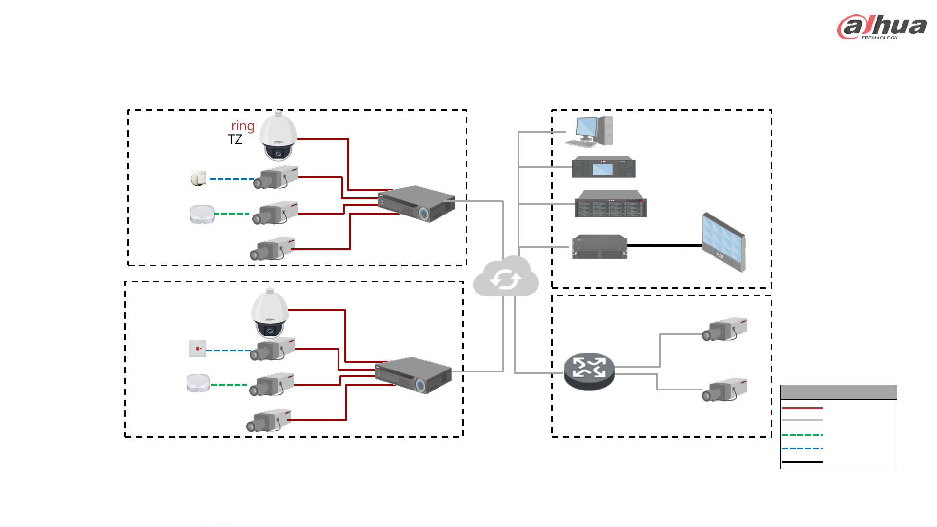
Remote System – Topology
Legend
Coaxial Cable
Network Cable
Audio Cable
Data Cable
HDMI
HDCVI Recorder
HDCVI Camera
HDCVI PTZ
Pickup
Sensor
NVR
IP Camera
IP PTZ
Pickup
Button
Storage
Client
Controller
Management
Platform
TV Wall
HDCVI Monitoring
IP Camera
IP Monitoring
IP Monitoring
Monitoring Center
Network
Page 4
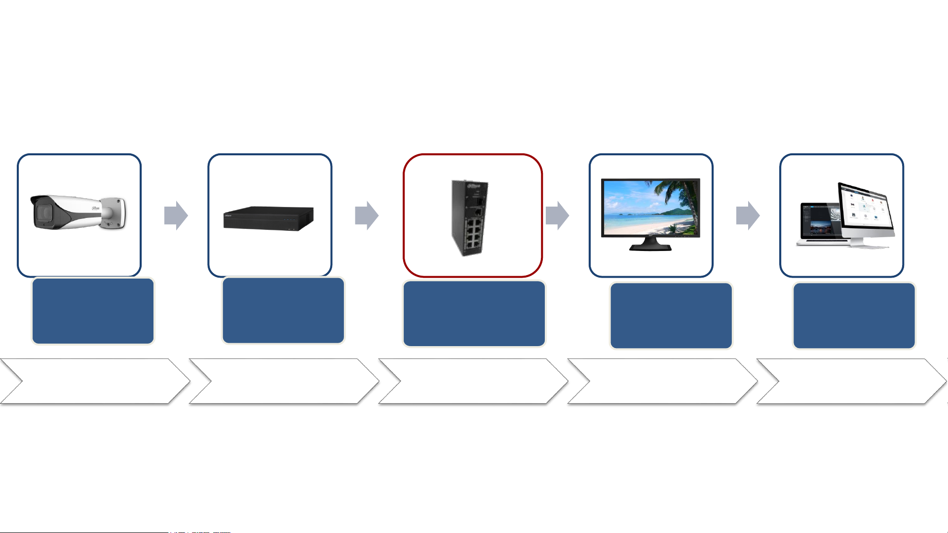
Product Selection Overview
1. Camera
Selection
2. Recorder
Selection
4. Display
Selection
5. VMS
Selection
3. Transmission
Selection
Camera
Accessories
Recorder
Accessories
Transmission
Accessories
Display
Accessories
VMS Accessories
Page 5

CONTENT
1
2
6
3
4
5
Camera Introduction
CCTV General Introduction
Recorder Introduction
Transmission Introduction
Display Introduction
VMS Introduction
Page 6

Camera Selection Overview
– The Installation Environment
• Angle of view, Focal length, DORI Distance, Light condition, Protection, etc.
– The Image Quality
• Lens, Sensor, Resolution, Frame rate, Image processing, etc.
– The Appearance
• Bullet, Dome, etc.
– The Interface
• Audio, Alarm, SD card, etc.
– The Intelligent Video Analysis
• IVS, Face detection, etc.
Page 7
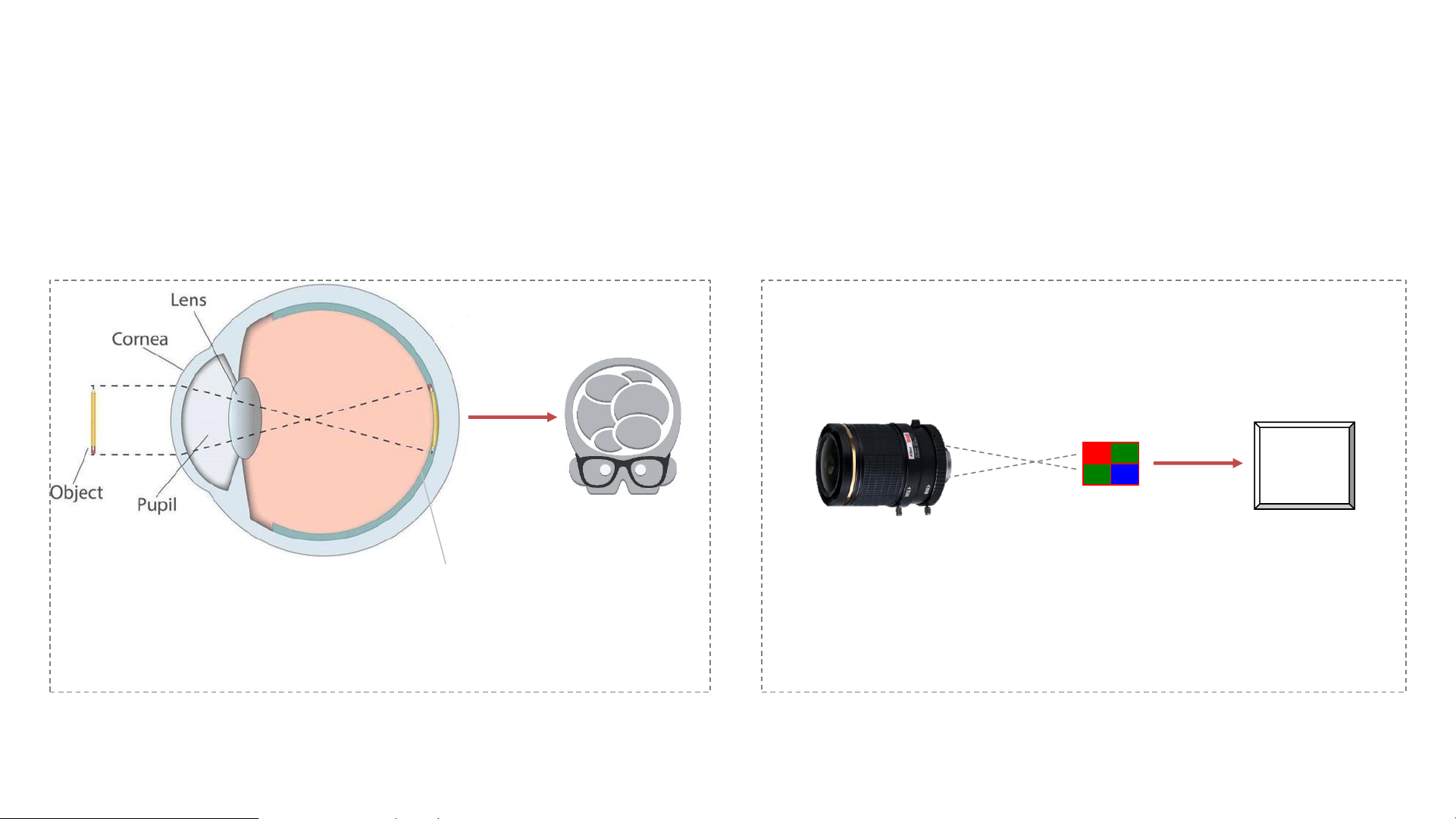
Camera Working Principle
• The working principle of camera is similar to the human vision system.
• It is mainly composed of three parts: the lens, the sensor, and the processor(DSP,ISP).
Human Vision System
Retina
(Feel the light and imaging)
ISP
DSP
Camera
Lens
(Cornea+Pupil+Lens)
Sensor
(Retina)
Processor
(Brain)
Brain
(Control, Analysis)
Cornea+Pupil+Lens
(Focus the light to retina)
Page 8

Camera – Sensor Type
• Common sensor type: CMOS, CCD.
– CCD: image effect is better, but the power consumption is large, and wide dynamic performance is poor,
and the price is higher.
– CMOS: high integration, and price advantage is very obvious, and wide dynamic performance is good.
Sensor Type
Power
consumption
Illumination effect
Dynamic Range Price
CCD Large Better Bad High
CMOS Small Normal Better Economical
Page 9
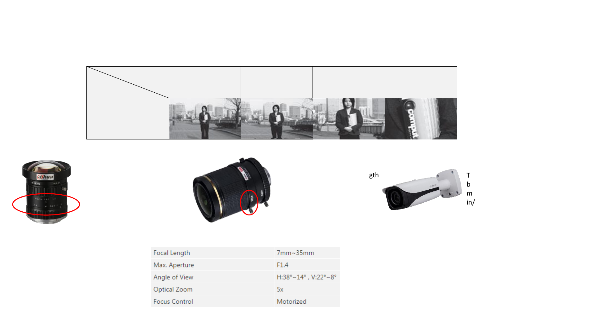
Camera – Lens Focal Length & Angle of View
Manually adjust the focal length
adjustment ring.
WIDE (W)<-->TELE (T)
It’s convenient for installation.
Fixed focal length camera
always be installed in a fixed
scene and the target object is
in a fixed area. (e.g. 8.5mm)
Zoom camera supply power for
motorized lens
The focal length can be adjust
by motor remotely in operation
menu to realize optical zoom
in/ zoom out
Fixed Lens
Focal Length
Distance
f=2.8mm
WIDE (W)
f=3.5mm f=8mm f=30mm
TELE(T)
2m
Varifocal Lens
Motorized Zoom Lens
Lens focal length can be
searched in specifications:
E.g. The lens is motorized zoom lens, 7mm~35mm(35/7=5x optical
zoom). When the focal length is 7mm, the Angle of view is
H(horizontal) 38°, V(vertical) 22°. When the focal length is 35mm,
the Angle of view is H(horizontal) 14°, V(vertical) 8°.
Why the FOV-H is different from FOV-V? Because the sensor is
rectangle, not a square.
Page 10
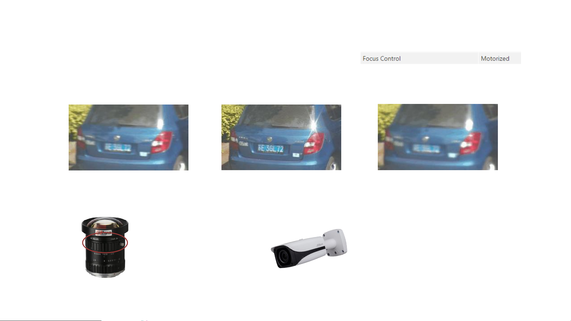
Camera – Lens Focus
• The focus function can make the light focused to give the clear object imaging on the sensor.
Manually adjust the focus
adjustment ring
NEAR (N)<-->FAR (∞)
FAR too much NEAR too muchAppropriate Focus adjustment
Manual Focus
Motorized focus camera supply
power for motorized focus lens
The focus can be controlled
remotely in operation menu
Motorized Focus
Lens Focus mode can be searched in specifications:
Page 11
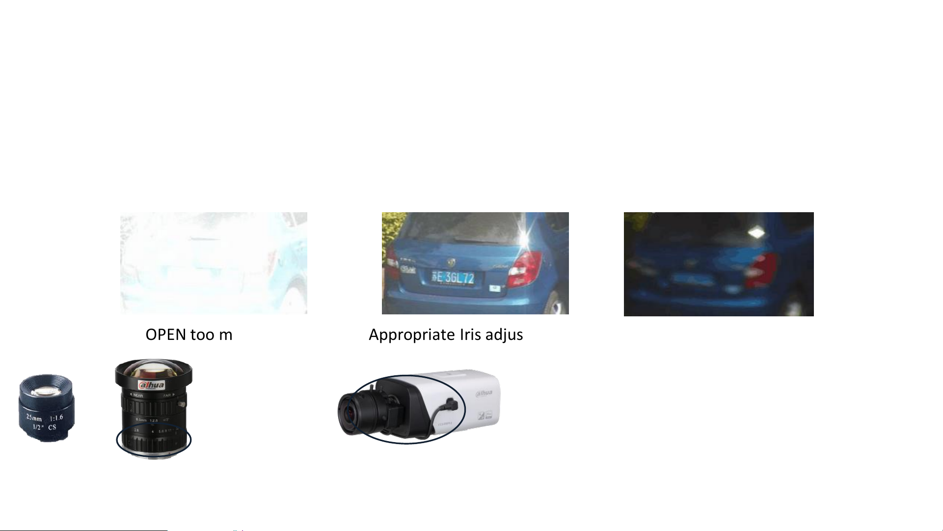
Camera – Iris/Aperture
• The lens Iris can control the light which get through the lens so that images can be sharp, clear and correctly
exposed with good contrast and resolution. Generally speaking, the larger aperture opening means the
camera has better anti-shake performance.
OPEN too much CLOSE too muchAppropriate Iris adjustment
Manually adjust the Iris
OPEN (O)<-->CLOSE (C)
Manual Iris
Auto iris camera supply power for auto Iris lens
The iris can be controlled automatically to adapt
for different environment.
Auto Iris
Fixed Iris
Page 12
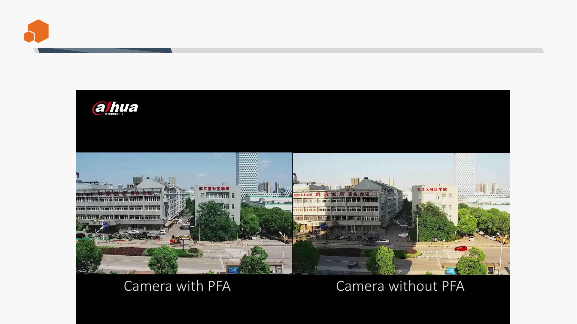
The PFA (Predictive Focus Algorithm) adopts Dahua newly-developed focus algorithm, which ensures the
camera image stays focused while zooming, and greatly improves user experience and enhances product
value.
PFA
Page 13
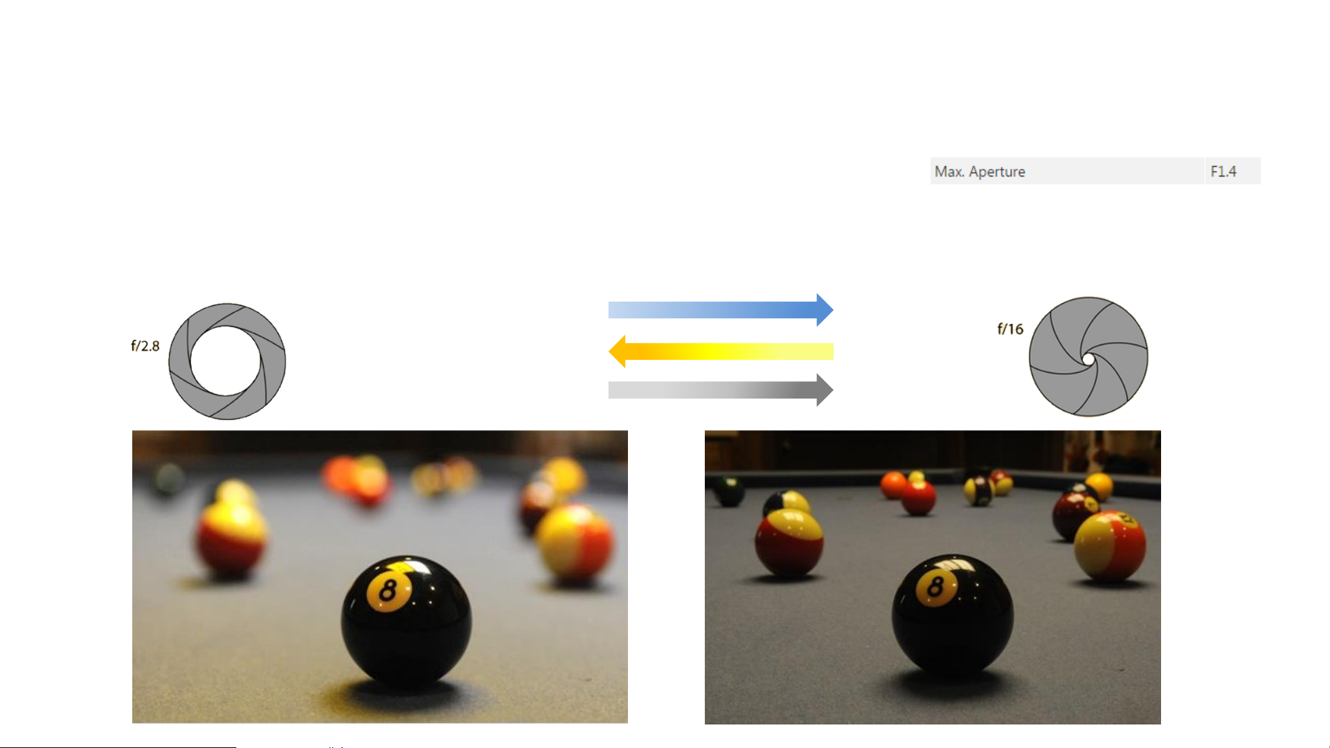
Camera – Different F-number Effect
• F-number = focal length / diameter of aperture.
– The smaller f-number, the larger aperture opening, the higher brightness, need less shutter time, and the
narrower depth of field, give the more contrast of the clear and vague.
F-number
Larger
Depth of field
Lower
Higher
Aperture opening
Smaller
Wider
Narrower
Lens F-number can be searched in specifications:
Page 14
Camera Video Performance
Resolution
DORI distance
BLC/HLC/WDR
White Balance
ICR
Low-light picture performance
Protection
…
Page 15

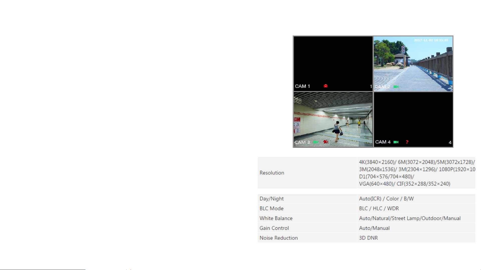
Camera – Resolution
• A camera’s resolution is defined by the number of pixels in an image provided by an image sensor.
• The higher the resolution of the lens and sensor, the clearer the picture, the larger the output image size.
(Generally, the lens resolution should be larger than sensor so that the sensor performance won’t be
wasted.)
• Common resolution: CIF, D1, 960H, 1M (720P), 1.3M, 2M (1080P),3M, 4M, 4K.
Resolution
Pixels
960H
960
*576P (480N)
1M
(720P)
1280*720
2M
(1080P)
1920*1080
4M
2688*1520
4K
3840*2160
Page 16
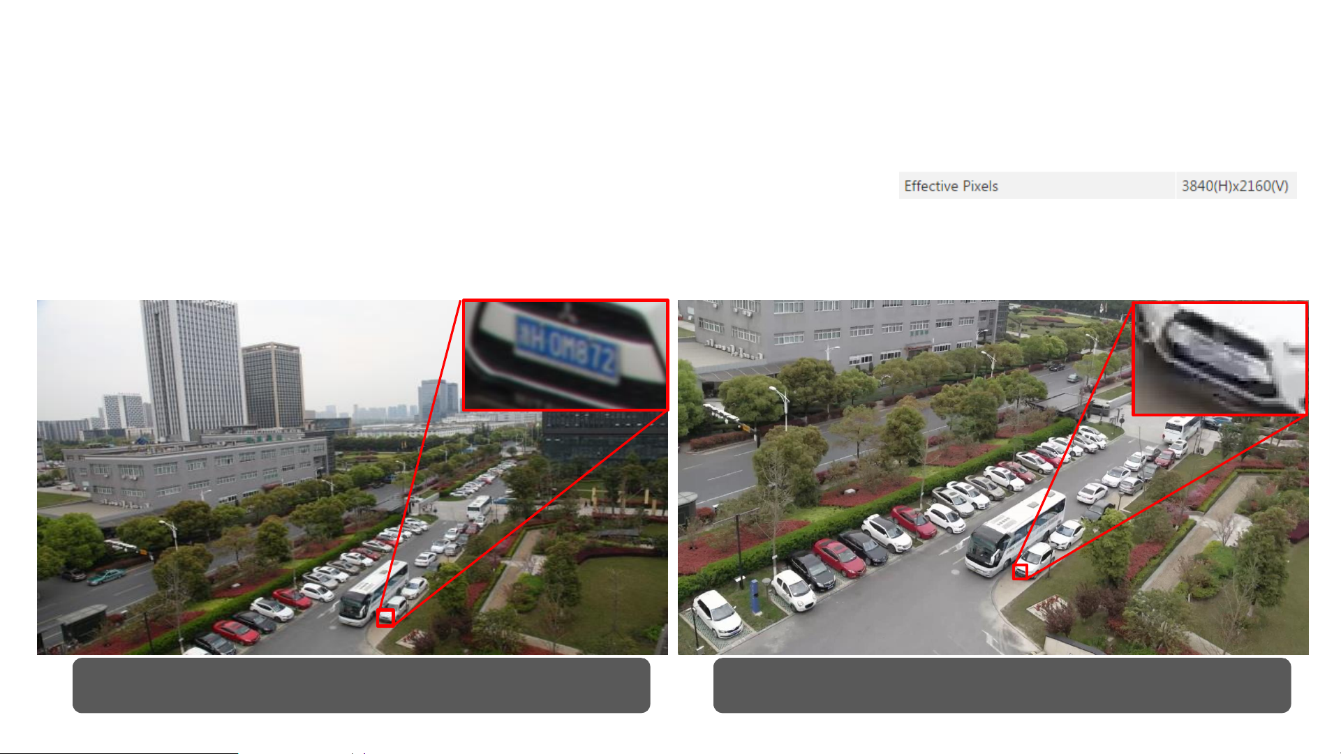
Camera – Resolution Comparison
• You can get more detailed information in a higher resolution picture even you
zoom in the picture in digital zoom mode.
– Digital zoom means enlarging the particular sections of a high-resolution image.
4K Camera 1080P Camera
Lens resolution can be searched in specifications:
Page 17

Camera – DORI Distance
• The DORI distance is to define the camera Detection/ Observing/ Recognition/
Identifying capability. It’s useful in camera selection and installation guide.
If you want to realize
___________ the object
You need the min. object size in the picture
Detect
25PPM (Pixel Per Meter)
1 meter object in the picture correspond to at least 25 pixels to make the camera detect it. (E.g.
Realize motion detection to trigger the alarm)
Observe 63PPM
Recognize
125PPM
(E.g. Realize license plate recognition)
Identify
250PPM
(E.g. Realize face features identifying)
E.g. A camera DORI distance is show as follows:
The camera focal length can be adjusted from 2.7mm(W--WIDE) to 13.5mm(T--TELE).
If you adjust the camera focal length as 2.7mm, the object in 46/18/9/5 meters away from the camera can be detected/observed/recognized/identified.
Page 18

Camera – BLC/HLC/WDR
• Sometimes the environment is complex such as backlight environment, and the pictures do work
well. So we need do some compensation for these application scenario.
• We can select the compensation mode for different requirements: BLC for backlight environment,
HLC for spotlight environment, WDR for a scene with a large difference between light and dark,
etc.
– Note: If we select the BLC mode of a camera, we can’t use HLC/WDR mode at the same time. The
function is switchable for different application scenarios.
Page 19

Camera – BLC
• BLC (Back Light Compensation) technology is to enhance the picture brightness so that we can
see the object even in back light.
BLC off
BLC on
Page 20
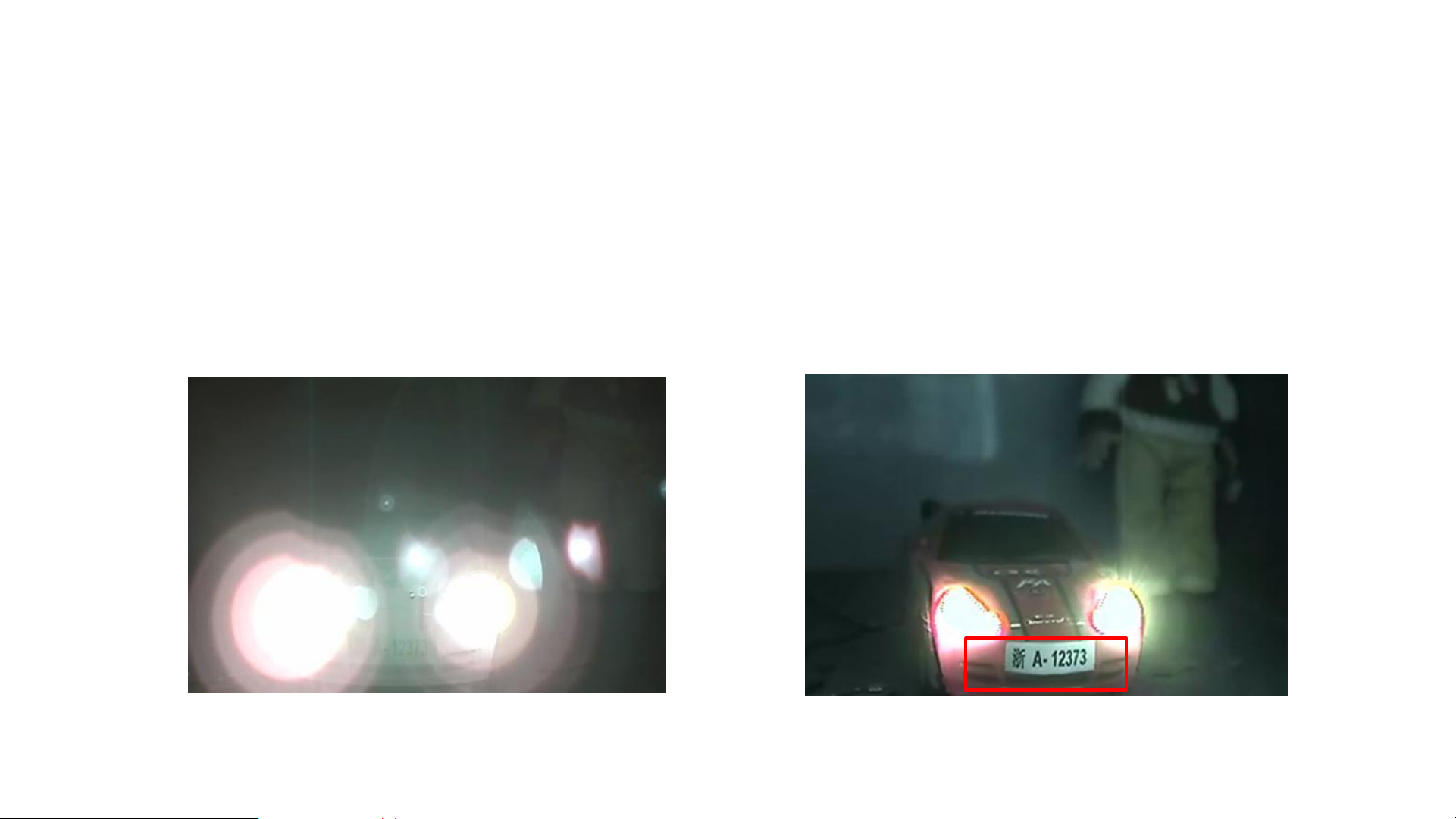
Camera – HLC
• HLC (High Light Compensation) can reduce the brightness of the entire to suppress the strong spot in the
picture and use the additional illuminator to make the dark areas get compensation to get a clear image.
This function is often used to see the license plate number at night to suppress the car light effect.
HLC off HLC on
Page 21

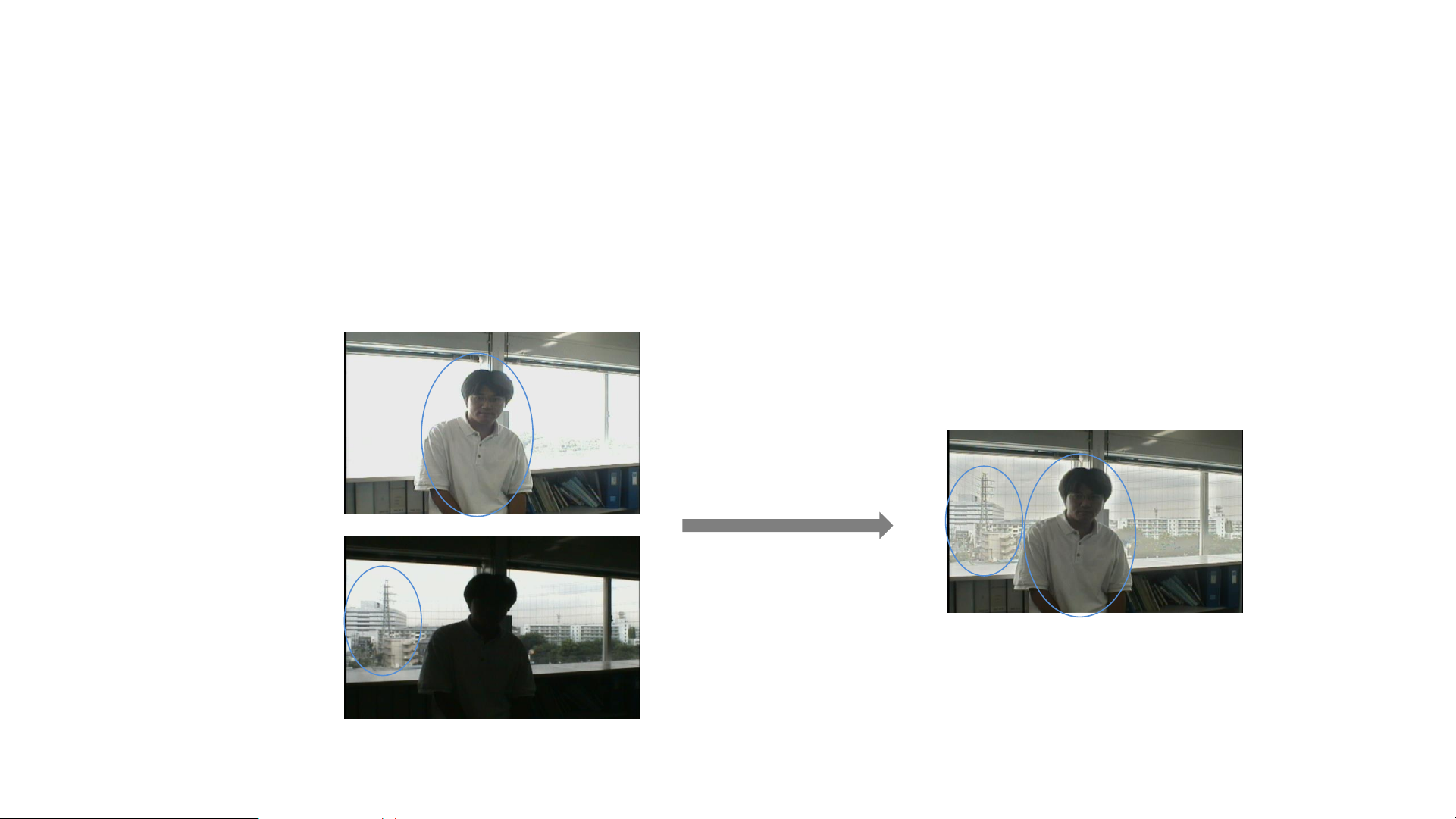
Camera – WDR (1/2)
• WDR (Wide Dynamic Range) cameras often incorporate an image sensor that takes different
exposures of a scene (e.g., a short exposure for very bright areas and long exposure for dark
areas) and combine them into one image, enabling objects in both bright and dark areas of a
scene to be visible.
• WDR does not apply to scenes that move objects quickly.
WDR off
WDR on
Page 22
Camera – WDR (2/2)
High
shutter speed
Ordinary
shutter speed
Synthetic effect
Combo
120dB true WDR principle: take 2 pictures (a high light picture to see the dark object, a low light picture to
see the bright object) and combine them to 1 picture.
140dB WDR camera takes 3 pictures , so we call it ultra WDR, which is better than 120dB true WDR.
Page 23
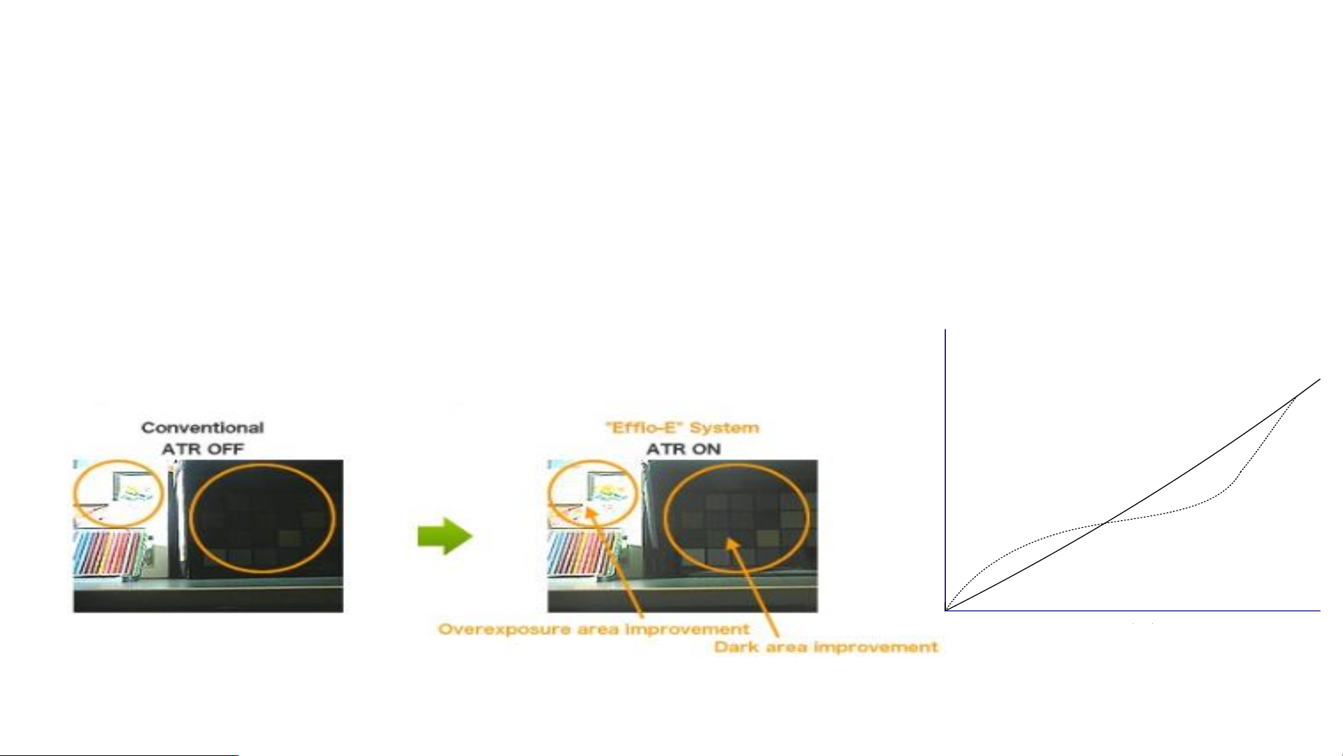
Camera – DWDR
• DWDR (Digital WDR) is for the camera which don’t support true WDR. It’s achieved through the internal
DSP algorithm, mainly for the brightness curve to do some correction, the dark curve will be raised and the
bright curve down, such as the right part of the dotted line, the overall effect
• The effect of true WDR is better than DWDR.
Page 24

Camera – BLC/HLC/WDR
• Sometimes the environment is complex such as backlight environment, and the pictures do work
well. So we need do some compensation for these application scenario.
• We can select the compensation mode for different requirements: BLC for backlight environment,
HLC for spotlight environment, WDR for a scene with a large difference between light and dark,
etc.
– Note: If we select the BLC mode of a camera, we can’t use HLC/WDR mode at the same time. The
function is switchable for different application scenarios.
Page 25
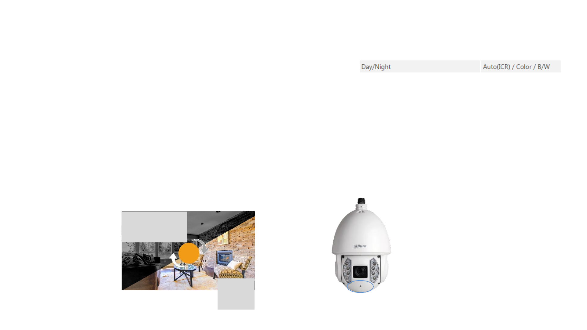
Camera – Color/Black and White
• The camera can be switched in Day/Night mode.
– In the day mode (color mode), the camera will give you a color picture.
– In the night mode (black and white mode), the environment is dark, the color effect is poor, so the camera will give
you the black and white picture to see the object clear.
– The camera DSP can switch the color/black and white mode automatically that the camera can judge whether it’s
day or night by analyzing the picture brightness or using the photo resistance to sense the environment brightness.
Also we can switch the color/black and white mode manually in operation menu.
Analyze the picture brightness
using the photo resistance to sense
the environment brightness
Day(C
olor)
Night(Black
White)
Day/Night info can be searched in specifications:
Page 26

Camera – ICR
• The sensor can sense the infrared light so that the picture will look red and purple. The camera can use the
ICR dual filter to solve the problem.
• The ICR dual filter consists of an Infrared Cut-off Removal filter and a full spectrum optical glass.
– Day: The infrared cut-off filter works, the IR light will be cut, so the sensor restores the true color.
– Night: The environment is dark, there’s little visible light, camera will switch into the black and white mode, The DSP
will remove the infrared cut-off filter and make full-spectrum optical glass work to pass the infrared light through so
that the sensor takes full advantage of all the light, thus greatly improving the low-light performance.
ICR (color) ICR (night)
Page 27
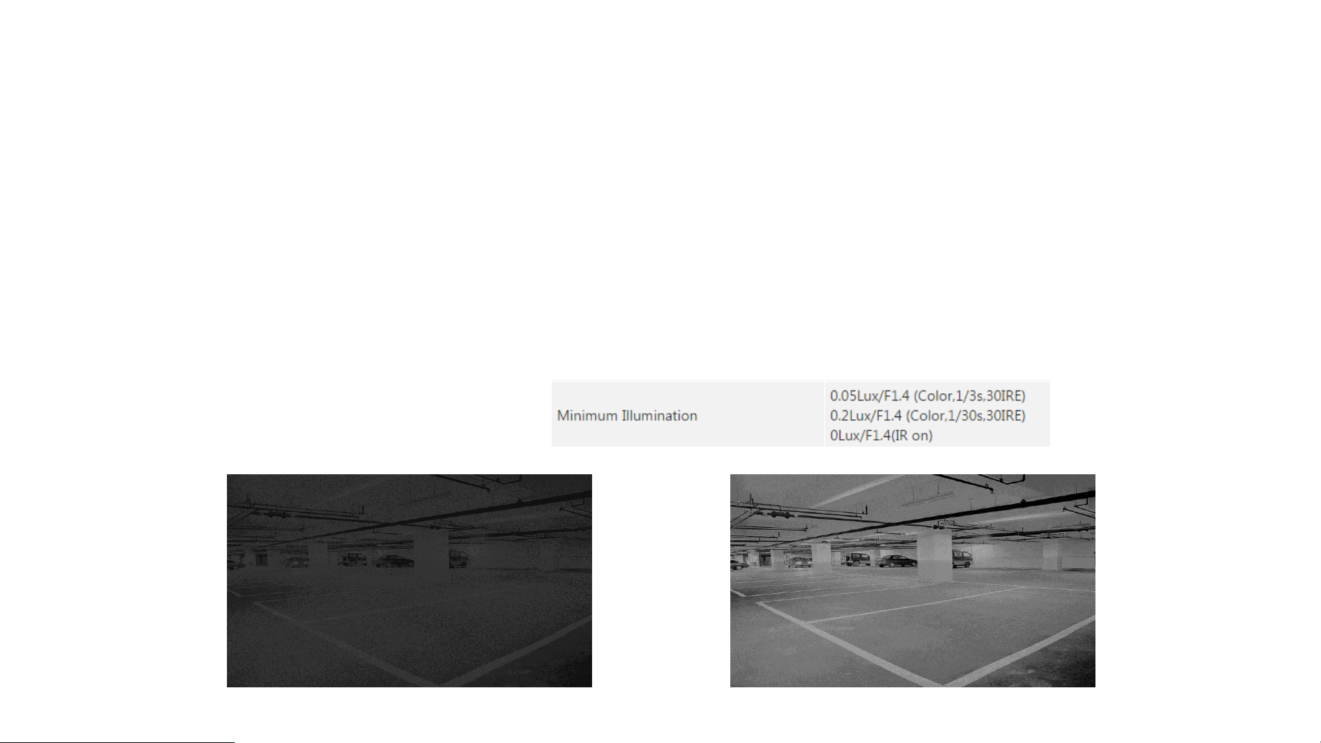
Camera – Low-light Performance
• In the night, Low illumination makes the camera difficult to focus, the image will be blurred and dark. To
solve the problem, we will take some method to improve camera low-light performance:
– Use a lens with large aperture, and use low speed electronic shutter to make more light pass through.
– Use a big sensor and improve the sensor performance to sense more light.
– Use the AGC technology to amplify the electric signals.
• We will use the min. illumination value(Lux as unit) to judge the camera low-light performance. The lower
the Lux value, the better the camera's sensitivity.
Low-light info can be searched in specifications:
Page 28
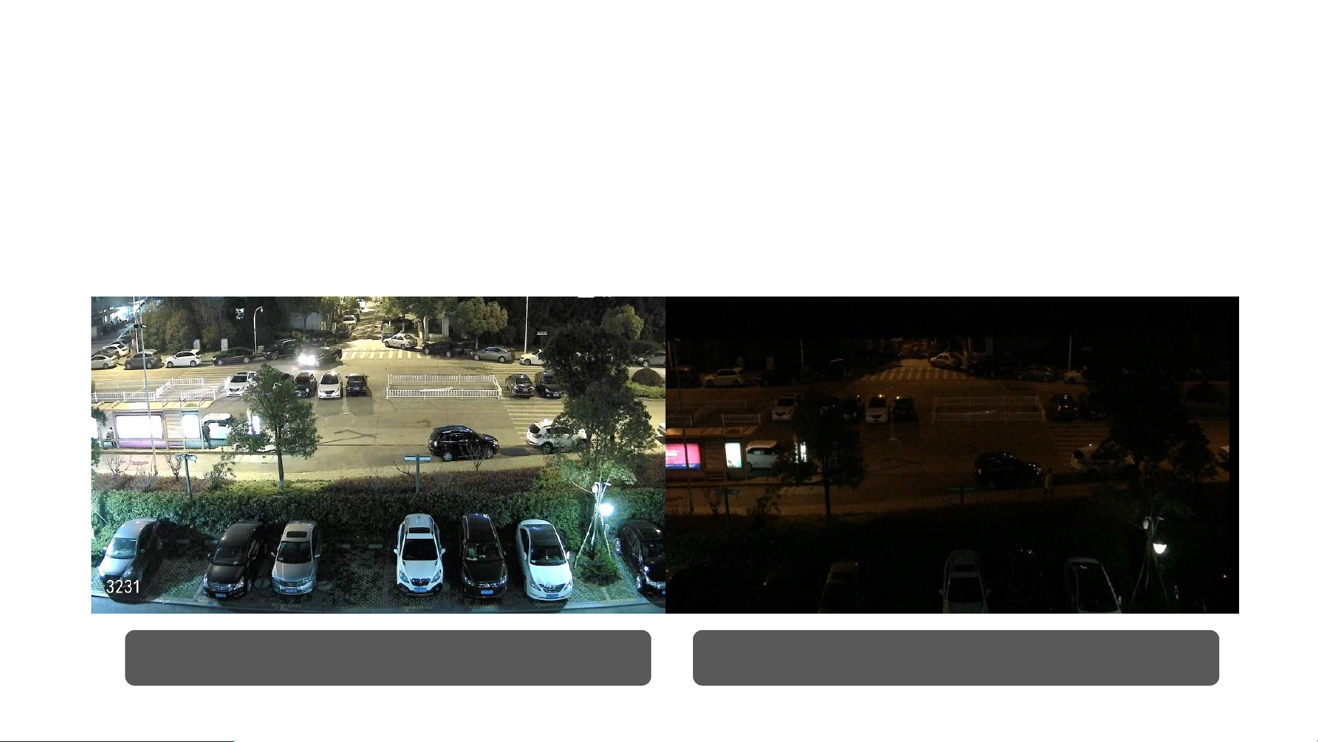
Camera – Starlight Technology
• The Starlight Technology can improve the camera low-light performance and make it deliver usable video
with minimal light. The starlight camera presents high quality colorful image with rich details even under
extreme lowlight environment (less than 0.01lux).
Snapshot by starlight Camera Photo taken by IPhone6S
Page 29
Camera – Noise Reduction
• In preview, signal and noise exist at the same time. through the DNR (Digital Noise Reduction)
technology can inhibit the noise in the screen, then obtain better quality images.
– 2DNR works by analyzing individual frames of video, identifying algorithmically and correcting those
pixels that likely represent noise. 3DNR additionally analyzes the differences between successive frames
in order to adjust pixels and improve fidelity.
3DNR off 3DNR on
Page 30
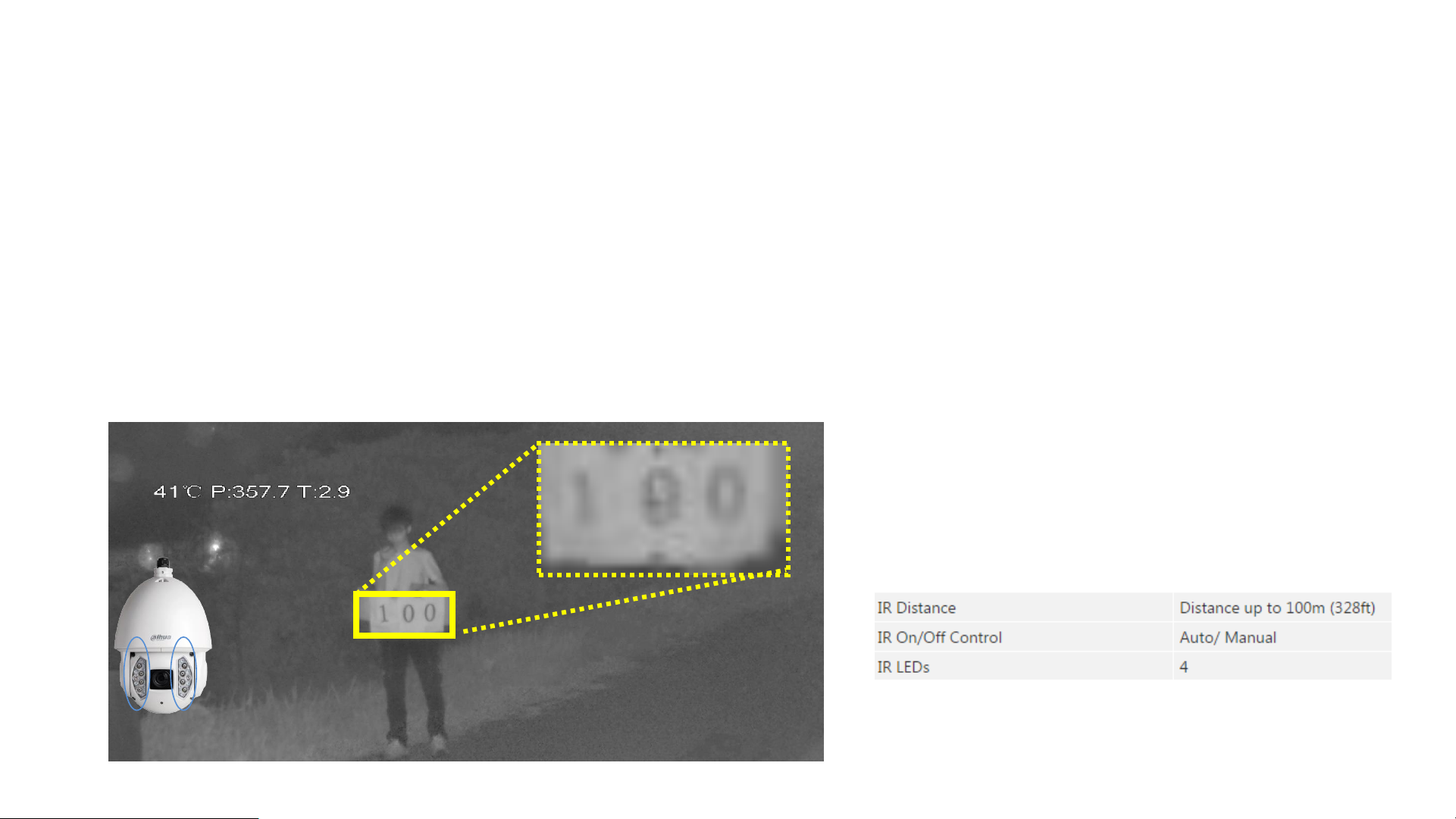
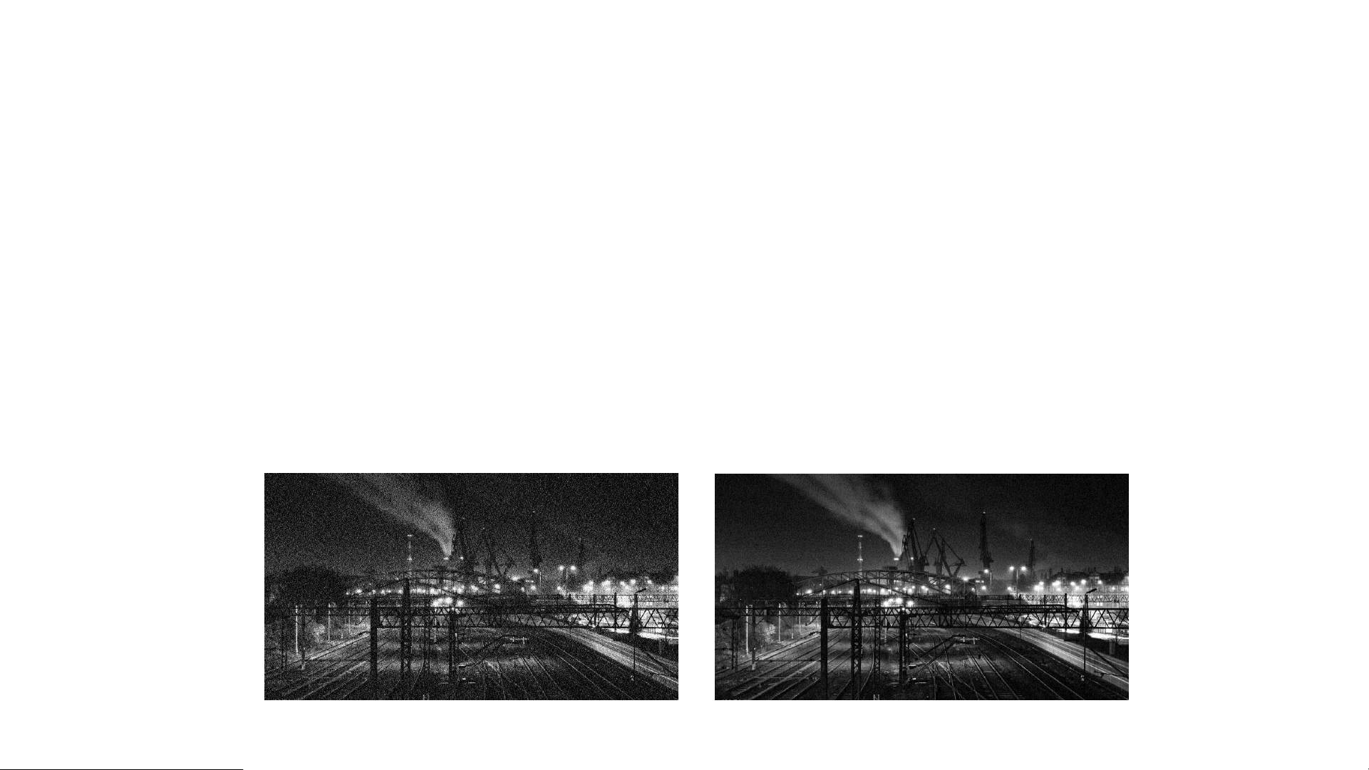
Camera – IR Camera
• IR camera means that the camera with built-in IR illuminator. When the environment is too dark, the
camera will turn on IR light automatically according to the photosensitive resistance feedback signal and
the camera will provide more details in the black and white mode.
– The luminescence conversion efficiency of IR is fixed. The Larger the IR angle, the shorter the IR distance.
– E.g. The following image shows the effect of IR (when the IR distance is 100m).
IR info can be searched in specifications:
Page 31

Camera – Smart IR
• Sometimes, the picture will have the centralized overexposure problems because the object is near and all
the infrared lights work together. The smart IR technology can detect the brightness change of IR light by
the advanced DSP algorithms, to avoid the centralized overexposure problems.
General IR Camera Smart IR Camera
Page 32

Camera – Protection
• Sometimes, the camera installation environment is bad, so we need some protection for the cameras.
– E.g. The outdoor camera need water proof to avoid the water from rain, dust proof to avoid the environment dust
and wide working temperature range to avoid hot/cold weather.
– Some protection have the certificated grade so that we can know the performance of the camera for different
installation environment.
Protection info can be searched in specifications:
Page 33

Camera – Protection
IP 6 7
Ingress Protection
Dust Proof Level
Water Proof Level
Dust
Proof
Level Description
0
No protection against contact and ingress of objects
1
Any large surface of the body, such as the back of a hand, but no
protection against deliberate contact with a body part
2
Fingers or similar objects
3
Tools, thick wires, etc.
4
Most wires, slender screws, large ants etc.
5
Ingress of dust is not entirely prevented, but it must not enter in
sufficient quantity to interfere with the satisfactory operation of
the equipment.
6
No ingress of dust; complete protection against contact
(dust
tight).
A vacuum must be applied. Test duration of up to 8 hours
based on air flow.
Water
Proof
Level Protection against
0
None
1
Dripping water
2
Dripping water when tilted at 15
°
3
Spraying water
4
Splashing of water
5
Water jets
6
Powerful water jets
7
Immersion, up to 1
m depth
8
Immersion, 1
m or more depth
9
Powerful high temperature water jets
Outdoor Scenarios Requirement : ≥IP65
Page 34

Camera – Protection
IK 10
Impact Protection Vandal Proof Level
Vandal Proof
Details IK10
Impact energy (joules) 20
R mm (radius of striking
element)
50
Material steel
2
Mass kg 5
Pendulum hammer Yes
Spring hammer No
Free fall hammer Yes
Vandal Resistance means the housing protect device against mechanical collision.
Page 35

Camera – Protection
• Special Housing
– Adapt to the installation requirements of different environments.
Anti-Explosion
Anti-Corrosion
Page 36

Camera Interface
Video
Audio
Alarm
Power
UHD video
Audio
Control data
P WER
Page 37

Camera – Video
• Video: made up of continuous pictures for a time.
– 1 picture in the video is called a frame.
– Frame Rate (FPS) → Frames per second Higher Frame, more fluent video, more realistic
Frame 1
Frame 2
Frame 3 Frame 4 Frame 5
1s Video
Frame rate: 6fps
Frame 6
Interval 0.2s 0.2s 0.2s
0.2s 0.2s
Frame 1 Frame 2 Frame 3
1s Video
Frame rate: 3fps
Interval 0.5s 0.5s
Page 38

Camera – Video Standard
• The camera video standard can be set as PAL mode or NTSC mode.
– PAL (Phase Alternating Line)
• Used in the countries whose power frequency is 50Hz.
• We should set the camera video standard mode as PAL in China, Russia, Europe, Egypt, etc. Otherwise the video will flicker and
out-of-step.
– NTSC (National Television System Committee)
• Used in the countries whose power frequency is 60Hz.
• We should set the camera video standard mode as NTSC in USA, Japan, etc. Otherwise the video will flicker and out-of-step.
• Generally, the frame rate should be more than 25fps(PAL—in China, Russia, Europe, Egypt), or
30fps(NTSC—in USA, Japan), can realize the real-time effect that the video looks continuous and fluent.
Page 39

Camera - Analog Camera Video Output
• The ANALOG system always use the coaxial cable to transmit the analog video signal.
Coaxial cable(point to point connection-camera
connect with recorder directly)
Recorder Display
Dahua HDCVI Cam
(Up to 4K resolution)
Traditional Analog Cam
(Up to 960H resolution)
Page 40

Camera - Network Camera Video Output
• The NETWORK system always use the network cable to transmit the digital video stream.
IPC
NVR Display
IPC
Network
IPC: Network Camera
NVR: Network Video Recorder
Network cable(the device
connect with switch)
Page 41

Page41
Copyright © 2017 Dahua Technologies Co., Ltd. All rights reserved.
Analog System Features
No Delay
As analog system, HDCVI can present
vivid image quality without delay.
Lossless
Without encode/decode process, no
image loss of preview
Data Security
As analog system, HDCVI can best
prevent cyber-attacks
HDCVI
IPC
HDCVI Recorder
NVR
HD image
Blur image
P2P
transmission
Video encoding
The 2ndvideo processing
& encoding/decoding
The 2ndvideo decoding
HDCVI Follows analog system advantage features
Page 42

Camera - Network Camera Video Stream
• What is stream?
– It’s the compressed image data, used to evaluate video data volume in an instant time. The stream unit: Bit Rate (bps -- bit
per second)
– Higher resolution, higher frame rate means more data and greater stream
– Stream Type: Video Stream, Audio Stream, Composite Stream(Video Audio)
– Some IPC can give more than 1 video stream in different resolution for different device, such as PC, Mobile Phone.
• Why we need compress the image data?
– Reduce data volume to realize convenient transmission and storage, and save the storage space. (E.g. 1MB file transmission
and storage need less time and space than 1GB file)
• How to compress the image data?
– Use the encoding technology. (H.264, H.265)
– Use the stream control technology. (CBR, VBR)
Stream info can be searched in specifications:
Page 43

Video Encoding Technology
• H.264 Compression(international standard) take the difference between the former and the latter
pictures into consideration, and only compress the changed part. If there’s a small rectangle moves, H.264
will record the direction and distance, and the rectangle itself will not be compressed twice.
Object
P FrameI frame
Motion
Vector
Searching
Area
Correspon
ding
Object
Compression info can be searched in specifications:
Page 44

Noise Suppression Technology
• Adopts different noise reduction levels
Video Encoding Based on the Video
Contents Analytics
• Dynamic ROI(Region of Interest) & dynamic GOP(Group of Pictures)
• Flexible reference frame structure
Video Encoding Technology
• H.265 Compression(international standard) is better than H.264 with higher compression rate.
• Smart H.265+ Compression(proprietary standard) is intelligent encoding algorithms developed by
Dahua technology based on H.265. (Smart codec, lower bit rate, less storage)
H.265+
HD
D
90%
H.264
HD
D
FULL!
H.265
HD
D
50%
01
02
03
Advanced Bit Rate Control Algorithm
• Scene adaptive encoding strategy
Page 45

Stream Control Technology
• We can set a referenced stream value so that the encoding processor will adjust the compression
rate to control the stream in the required range.
– E.g. For indoor scenes, due to less moving objects, the configuration stream is 2Mbps to meet the requirements. For
road monitoring scenarios, due to the scene changes, you may need to configure the bit rate to 4Mbps.
• We can set different stream type for different application scenarios.
– CBR(Constants Bit Rate) means the stream will be controlled in a constant range.
• Advantage: The stream is steady.
• Disadvantage: The picture quality will go down when the video has a lot dynamic information.
– VBR(Variable Bitrate) means the stream is variable according to the video dynamic information.
• Advantage: The picture quality is good even the video has a lot dynamic information.
• Disadvantage: The Stream will be large and need more storage when the video has a lot dynamic information.
Stream control info can be searched in specifications:
Page 46

Camera – Audio
• Sometimes, when we look at the video, we need the audio information to know what happened.
– E.g. At the retails checkout counter, in the lift, in the meeting room, etc.
• The camera audio function can be realized by several modes: Camera connect with the pickup; Camera with
a built-in mic.
• The audio signal can be output with the video signal, which called composite stream.
Built-in mic camera always be used in the
small room or where the camera is nearby
the sound source.
Built-in Mic
Pickup always be used in the big room or
where the camera is not nearby the sound
source.
Pickup Connection
Audio Interface info can be searched in specifications:
Page 47

Camera – Audio Output
Traditional Audio
Broadcast Quality Audio
IPC
Video + Audio
Network
Analog Camera
Video + Audio(Broadcast Quality Audio)
Note: In the analog system market, only the Dahua
HDCVI camera support audio coaxial transmission
Camera Audio
Output Interface
Recorder
Monitor
Speaker
Page 48

Camera – Alarm
• Sometimes, when we look at the video, we need the alarm information to warn us what happened.
– E.g. At the chemical plant, in the safeguard system, etc.
• The camera alarm function can be realized by several modes: Camera analyze the video to give the alarm
signal; Camera connect with the alarm detector; Camera with built-in alarm sensor.
• The alarm signal can be output with the video signal.
Alarm sensor always give the additional
information that we can’t get from the
video.
Alarm Detector Connection
The camera can detect some exception
event by video analysis, such as motion
detection.
Video Analysis
IoT camera is very convenient for alarm
and video monitoring because of the built-
in sensor.
IoT Camera (Built-in Sensor)
Alarm Interface info can be searched in specifications:
Page 49

Camera – Alarm Output
IPC
Network
Analog Camera
Video + Alarm
Camera Audio
Output Interface
Video + Alarm
Recorder
Monitor
Siren
Page 50

Camera – Power Input
• The camera need power to start work.
• Generally, we have several modes to supply power for camera: Power adaptor( Some camera support
12VDC input; Some camera support 24VAC input); PoC(Power over Coax)/ PoE(Power over Ethernet) power
supply, which can make installation more convenient and save the labor cost.
• If we use the power adaptor for different cameras, please pay attention for these notes:
– The power adaptor output voltage(unit: V) should be the same as the camera input, otherwise the camera may be
damaged.
– The power adaptor output power (unit: W)(the product of voltage and current(Unit: A)) should be more than the
camera power consumption, otherwise the camera may can’t work normally.
Power supply info can be searched in specifications:
Page 51

Camera – Power Input
IPC
In network system, camera is
supplied power from PoE
switch or recorder through
the network cable
Network
Analog Camera
Note: In the analog system market, the Dahua HDCVI support PoC but the traditional
analog system doesn’t support PoC
Recorder
In analog system, camera is supplied power from
recorder through the coaxial cable
Camera Power
Input Interface
12VDC Power Adaptor 24VAC Power Adaptor
Page 52

Camera Categories
Classified by output signal
Classified by appearance
Classified by application scenarios
…
Page 53

Camera - Categories
• In the video surveillance industry, we have traditional analog camera, traditional SDI camera, HD analog
camera, network camera, etc.
– Traditional analog camera/SDI camera use the coaxial transmission, the resolution is low, so they’re instead by HD
analog camera and network camera.
– HD analog camera use the coaxial transmission, can easily instead of the traditional cameras. In the HD analog
industry, the HDCVI (up to 4K, developed by Dahua, leading the HD analog development)/ TVI/ AHD(up to 5MP) is
the most used system.
– Network camera use the network transmission, can support higher resolution and more intelligent functions, can
realize convenient system expansion.
Page 54

PTZ Cam
Mobile Cam
Eyeball
Dome Cam
IR Bullet Cam
Box
Cam
Speed Dome
Cam
Vandal-proof
Dome Cam
Camera - Appearance
Panoramic Cam
Small
PIR IoT
Parking
lot
Page 55

Camera - Application Scenarios
Entrance
Corridor
Corner
Panoramic
ATM
PIR
Long Distance Monitoring
Page 56

Camera Calculator – Tool Use
• Use the Camera Calculator Tool to help the camera
installation and deployment.
– Select the Camera Type
Page 57

Camera Calculator – Tool Use
• Use the Camera Calculator Tool to help the camera
installation and deployment.
– Select the Camera Model->Set the Installation parameters to see
the result.
Page 58

Camera Calculator – Tool Use
• Use the Camera Calculator Tool to help the camera
installation and deployment.
– Select the Camera Model->Set the Installation parameters to see
the result.
PPM Introduction
2D View
3D View
Image View
Page 59

CONTENT
1
2
6
3
4
5
Camera Introduction
CCTV General Introduction
Recorder Introduction
Transmission Introduction
Display Introduction
VMS Introduction
Page 60

Recorder Selection Overview
– The Signal type
• NVR (only for IP system), HCVR/XVR (IP, HDCVI, CVBS, TVI, AHD), etc.
– The Signal resolution
• 4K@15fps, 4M@30fps, etc.
– The HDD capacity
• The video stream size, the record time, etc.
– The Interface
• Audio, Alarm, USB, Network Port, etc.
– The Intelligent video analysis
• IVS, Face detection, etc.
Page 61

General Recorder Working Principle
• The general recorder include DVR (Digital Video Recorder ) and NVR ( Network Video Recorder ).
– The main function of recorder is to preview/ playback the video and record the video data.
AD
Encode
EncodeAD
NVR
DVR
Network
Analog Camera
IP Camera
Network
Page 62

DVR Working Principle
• DVR ( Digital Video Recorder ) is suitable for analog system, connected with analog cameras(via coaxial interface).
DVR has video capture, coding compression, recording, decoding, transmission functions, etc.
• Because the DVR support decoding, so it can also connect with network cameras(via Ethernet interface) .
• Dahua DVR called XVR.
Analog Camera
(Preview)
Video Capture
Coding Compression
Network Surveillance
(Preview)
Decoding
Display
(Playback)
Decoding
Network
Web DSS
IPC
Real-time Preview
Real-time Recording
Real-time Playback
Recording
Page 63

• NVR ( Network Video Recorder ) is suitable for network system, connected with network cameras(via
Ethernet interface) . NVR has recording, decoding, transmission functions, etc.
• Because the NVR don’t support encoding, so it can NOT connect with analog cameras.
NVR Working Principle
(Preview)
Decoding
Display
(Playback)
Decoding
Network
Web DSS
IPC
Realtime Preview
Realtime Recording
Realtime Playback
Recording
Page 64

Recorder Video Management
Device Management
Video Preview
Video Storage
Video Playback
Page 65

Recorder – Device Management
• A recorder can connect with several cameras so that realize a local management system, so we can monitor
more than 1 video at the same time.
– For the DVR, it can support analog camera & IPC input.
– For the NVR, it can only support IPC input.
– We use “channel” to define the device number.
DVR device input capability can be searched in specifications:
NVR device input capability can be searched in specifications:
Page 66

Recorder – Video Preview
• For the DVR, the analog video signal from camera can be convert to VGA/ HDMI signal to display on the
screen directly without encoding/ decoding. No compression means less resolution loss and no delay. So
the DVR and analog system always be used in casino, sports broadcast scenarios.
• For the NVR, the network video signal will be decoded and display on the screen. The decoding technology
should be the same as encoding.
– E.g. If the NVR support H.265 decoding, the camera can use H.265 encoding. If the NVR only support H.264 decoding,
the camera should use H.264 encoding even it can support H.265.
Compression info can be searched in specifications:
Analog Camera
(Preview)
Video Capture
Display
Network Camera
Encoding(H.265)
(Preview)
Decoding(H.265)
Display
Page 67

Recorder – Video Preview
• The recorder input capability should be better than the camera output performance.
– E.g. If the recorder support 30fps@4MP camera input, the camera output should be set less than or equal to
30fps@4MP even it can support 30fps@4K.
NVR decoding capability can be searched in specifications:
XVR decoding capability can be searched in specifications:
Dahua XVR support pentabrid input (HDCVI, AHD, TVI
is HD analog technology
developed by different
manufacturer)
HDCVI
CVBS
IPC
AHD
HDTVI
Page 68

Recorder – Video Storage
• For the DVR, the analog video signal should be convert to digital signal by A/D module and compressed by
encoding technology, then the data can be recorded in the HDD. The encoding technology has been
mentioned before in the camera introduction.
• For the NVR, the network video signal has been encoded in the camera, so the video stream can be
recorded in HDD directly.
NVR/ XVR recording capability can be searched in specifications:
The video can be recorded
manually, automatically
(continuously or triggered by some
event)
Page 69

Recorder – Local Video Storage
• The video is always recorded on the HDD.
– In video surveillance industry, the video will be recorded frequently, so we should use the surveillance HDD instead
of the PC HDD, to make the recording stable and reliable.
– The HDD capacity, size, interface should match with recorder.
– More cache memory means better HDD performance.
• Also we can select the SSD as storage medium.
– Less noise, higher reading/writing rate, higher antiknock performance.
NVR/ XVR HDD compatibility can be searched in specifications:
Page 70

Recorder – Network Video Storage
• Besides the internal HDD storage, the network storage is always used in some project because the network
storage can realize large capacity, high data security, good Read/Write performance.
– There are many ways to realize network storage: DAS (Direct Attached Storage)/ NAS (Network Attached Storage)/
SAN (Storage Area Network)/ Could Storage.
EVS
010110011010110101010101000001110010101010010101000110101011110001010101
Network Video Transmission Technology
(ONVIF/PSIA/RTSP/iSCSI )
Professional network storage
Page 71

Recorder – Cloud Video Storage
• Consumer cloud storage is very convenient for consumers to monitor the video anywhere from cloud via
network without HDD installation.
• Professional cloud storage is very convenient for big project to realize higher performance and reliability.
Home & SME Cloud Surveillance
Web-based cloud storage and video
services, a new profit recourse for SIP
Safe City Cloud Surveillance
Massive storage capacity with high
availability and efficiency
Intelligent Traffic Surveillance
Combined with cloud structured analysis,
enabling fast vehicle and individual targeting
Page 72

Recorder – Video Storage Capacity
• The video storage capacity depends on the channel number, video stream per channel and the storage
duration.
– The HDD capacity unit is TB.
• 1TB=1024GB,1GB=1024MB,1MB=1024KB, B(Byte) = 8bit, bps = bit/s
Code format
Resolution
Bit Rate
Video
Compression
Bit stream size (ma
x)
960H
960*576
25/30
fps
H.265
1Mbps
720P
1280*720 1Mbps
1080P
1920*1080 2Mbps
4MP
2688*1520 4Mbps
4K
3840*2160 8Mbps
Storage capacity per channel s (unit TB)
Video stream per channel v(unit Mbps)
Video recording day d
Video recoding hour per day h
The calculation is as following:
s = v÷8×3600×h×d÷1024÷1024 (reference only)
v÷8 Mbps-->MBps, ×3600×h×d MBps--> MB, ÷1024÷1024 MB-->TB
Then we can calculate the HDD quantity we need.
How to know the video storage capacity?
How to know the video stream per channel?
It’s related to the resolution, bit rate, video compression (reference only)
Page 73

Recorder – Video Storage RAID Technology
• RAID(Redundant Array of Independent Disks)
technology combine several disks as a disk group to make
the storage more stable, faster and realize data redundancy.
– There are many different RAID technology for different
combination of disks.
– Redundant data can help user to retrieve the data when
some HDDs got broken to make data safe.
– RAID has better storage performance than single disk.
RAID
RAID 0 RAID 1 RAID 5
RAID 6
RAID 10
Some recorder support RAID0、RAID1、RAID5、RAID6、RAID1 and one-key setup
RAID info can be searched in specifications:
Page 74

Recorder – Video Storage RAID Technology
• RAID0 (Stripe)
– RAID0 combine all the disks and do
virtualization but without redundancy
check, which makes the whole system with
great performance but unable to afford
the risk of destroy of disk. RAID0 capacity
is the total of disk capacity.
• RAID1 (Mirror)
– RAID1 copies all the data from one disk to
another, which makes the data absolutely
stable but the user ratio lower and the
storage cost higher.
RAID 0
RAID 1
RAID5
Support proper functioning when one disk doesn’t work. Use ratio is
high (N-1), Read/Write Speed is fast. RAID5 is most common used RAID
level.
Q: How many HDD to set RAID5?
---A: At least 3 HDDs.
Also we can set hot spare HDD to make the RAID group work more reliable.
Private hot spare is spared for the one RAID 5 group and the public hot
spare is spared for all the RAID 5 groups.
Page 75

Recorder – Video Playback
• Sometimes, if something happened and we need playback function to find the evidence from the recorded
video. Some recorder support multi playback mode for different requirements.
• The recorder will decode the storage data and then convert to the VGA/HDMI signal to display on the
screen.
Display
(Playback)
Decoding
External storage
(eSATA, USB disk)
Playback info can be searched in specifications:
Page 76

Recorder Interface
Video
Audio
Alarm
PTZ Control
Debug
Power
NVR
XVR
Page 77

Recorder Interface Overview
Page 78

Recorder - Video Input
• XVR connect with HD analog cameras directly
via BNC interface. XVR connect with IPC via
Ethernet interface.
Ethernet interface
Network
PoE Ethernet interface
NVR
NVR connect with network
cameras via Ethernet interface. If
the NVR support PoE output, the
IPC can connect with the NVR
PoE Ethernet port directly to
realize plug&play.
XVR
BNC Video Input
Network
Page 79

Recorder - Video Output
• Recorder use the VGA/ HDMI port to display the
video on screen.
– HDMI can transmit the video with audio together but
the VGA can only transmit video signal.
– HDMI support higher resolution than VGA.
VGA Video Output
HDMI Video Output
Display info can be searched in specifications:
Page 80

Recorder - Audio Input
• There are several audio input mode:
– The audio signal can be input together with video signal from the camera.
– The audio signal can be input individually from the RCA audio input port.
RCA Audio Input
Audio input info can be searched in specifications:
Page 81

Recorder - Audio Out
• There are several audio out mode:
– The audio signal can be output together with video signal from the HDMI output to the screen which with built-in
speaker so that we can combine the video and audio signal to know what happened.
– The audio signal can be output individually from the RCA audio output port.
RCA Audio Input
Audio output info can be searched in specifications:
Page 82

Recorder - Audio Two-way Talk
• The recorder can support audio input and audio output, and the recorder can realize two-way talk with web
manager or platform via network for communication.
• The two-way talk function is always used for different security staffs.
Network
Two-way Talk
Page 83

Recorder - Alarm Input
• The recorder can manage the alarm signals, the input alarm signals can be used to trigger recording, alarm
out, etc. There are several alarm input mode:
– The alarm signal can be input together with video signal from the camera.
– The alarm signal can be input individually from the alarm input port.
• There are two types; NO (normal open)/ NC (normal close). If the alarm input device use external power, the device and the
NVR should the same ground.
Alarm input info can be searched in specifications:
Alarm input port
NO: Normal Open
Normal
Abnormal
NC: Normal Close
Normal
Abnormal
Page 84

Recorder - Alarm Output
• The recorder can manage the alarm signals, it can be triggered by alarm in, video analysis, etc. There are
several alarm output mode:
– The alarm signal can be output individually from the alarm output port.
• Some recorder only output a passive signal, so we need supply power for the external alarm device.
• NO:Normal open alarm output port.
• C:Alarm output public end.
Alarm output info can be searched in specifications:
Alarm output port
Page 85

Recorder – Power Input
• The recorder need power to start work.
– For some light models with less HDDs, we always use the DC power input. For some big models with more HDDs, we
always use the AC power input.
– When we select power adaptor, we should consider about the input voltage. The voltage should in the support range
of the device, otherwise the power will damage the device.
– Also we should consider about the power consumption. The recorder itself need power, the installed HDDs also need
power supply, and the PoE output need power supply. So the recorder with more HDDs and more PoE device
connections need more power consumption( more current). If the current is not enough, the device can’t work
normally.
Power supply info can be searched in specifications:
Page 86

Recorder – Power Output
• The recorder can supply power for the cameras via PoE/PoC or some power output port, which can make
installation more convenient and save the labor cost.
• If we use the recorder supply power for cameras, please concern about the limitation of output
consumption: DO NOT exceed the limitation, otherwise it may damage the recorder.
PoE Power output info can be searched in specifications:
PoC Power output info can be searched in specifications:
PoE camera connection is via individual PoE port: (Point to
point connection)
PoC camera connection is via BNC port just like non-PoC
camera connection: (Point to point connection)
Page 87

Recorder Storage Capacity Calculation
• Use the Disk Calculator Tool to help the storage capacity
calculation.
– Install the DiskCalculator Tool in ToolBox
1. Add Streaming: Add channels
2. Select the Channels number, Compression,
Environment, Resolution, Frame Rate, Audio to
calculate the Bitrate
3. Select the Recording Day
4. Click the Calculator button
5. The Request Capacity is as following:
Page 88

CONTENT
1
2
6
3
4
5
Camera Introduction
CCTV General Introduction
Recorder Introduction
Transmission Introduction
Display Introduction
VMS Introduction
Page 89

Transmission Selection Overview
– The Interface
• Video interface, Audio interface, Network interface, etc.
– The Transmission Cable
• VGA, HDMI, Coax, Network Cable, etc.
– The Communication Protocol
• HDCVI, Private, ONVIF, etc.
– The Switch
• POE, POE+, ePOE, etc.
Page 90

BNC&SDI
VGA
DVI' HDMI
Video Cable Introduction
• PS: Please avoid the excessive curve such as fold/twine, which will destroy the cable.
You can obey the vein of cable to tidy them up.
Page 91

Video Cable – Coaxial Cable
• Impedance 75Ω cable can reach to 500m
• Impedance 50Ω cable can reach to 185m
• PS: the distance in reality due to many factors such as interference and also the consumption lost
Thick (75Ω)
Diameter
Coaxial Cable
Thin (50Ω)
Application
Baseband (50Ω)
Bandwidth (75Ω)
TV analog signal
Digital signal
Page 92

Transfer BNC SDI VGA DVI HDMI
VGA Converter
Video Cable – VGA
• VGA
– VGA transmission distance is decided by the workmanship. The good cable can reach to 50m and
usually we use VGA extender to get far distance transmission
• Transmission Signal
– Analog signal
Page 93

• Transmission signal
– Doesn’t support audio
– Different structure decide to
transmit analog or digital signal
Transfer BNC SDI VGA DVI HDMI
DVI
DVI-I
Converter
Video Cable – DVI
Structure
DVI-A (12+5) analog signal
DVI-D (single 18+1 or dual 24+ 1 ) digital signal
DVI-I (single 18+5 or dual 24+5) analog signal
PS: DVI-I can change to VGA/BNC , DVI-D can’t change to VGA/BNC
Page 94

Transfer BNC SDI VGA DVI HDMI
HDMI Converter
Video Cable – HDMI
• HDMI
– digital signal transmission based on TMDS technology, compatible with DVI and support audio
• Material
– High density non-ferrous nylon braided mesh + high quality injection molding iron powder core + double-sided 4-layer aluminum
junction and high density double-layer shielding net + pure copper plating tin anti-oxidation wire core + copper shell gold-plated
15U"
Page 95

Network Cable Introduction
• Overview
– Network Cable is to connect the network from one network device to another. Network cable is the
basic part of network
• Classification
– Twisted-pair: the most common type of network cable, general cable is twisted pair, and the
transmission distance is 100 m, the theory of maximum distance is 150 m, but and line quality,
especially the crystal head production level has a lot to do
– Coaxial cable: The maximum transmission distance between the transmission distance of 75Ω is 500m
and the maximum transmission distance of 50Ω is 185m
– Optical fiber: transmission distance is 2 – 120KM
Page 96

Network Cable – Twisted Pair
• Classification
– UTP=Unshielded Twisted Pair
– STP=Shielded Twisted Pair
Video Manage Server
Page 97

Network Cable – Twisted Pair
• Now most RJ45 device support the automatic flipping function, it means that it will adjust the receive/send
function of the port.
Traditional hundred megabyte network use 4 cables to transmit network. But the thousand megabyte
network, it requires 8 cables.
Type Straight Through cable Crossover cable
TIA/EIA 586A
TIA/EIA 586B
Page 98

Network Cable – Optical Fiber
• Overview
– An optical conduction tool used to make a full reflection of light in a fiber made of glass or plastic
• Structure
– Fiber core, package layer, coating layer, tight cover
• Classification
– SMF
– MMF
Page 99

Network Cable – Optical Fiber
• Transmission distance
– MMF (Multi-mode Fiber) 2KM-5KM
– SMF (Single-mode Fiber) 20KM- 120KM
Fiber Attenuation
Coefficient (dB/km)
850nm 1300nm 1310nm 1550nm
Multi-mode 3 1 -- --
Single-mode -- -- 0.3 0.2
Factors
The medium used by the transceiver
The transmitting power of the transceiver
Sensitivity of receiver
Wavelength
Attenuation coefficient
Page 100

Network Cable – Optical Fiber
SMF
Transmit one mode light
Yellow cable
Wavelength 1310nm/ 1550nm
Transmission band is wide,
transmission distance is far
Single mode
MMF
Transmit multiple mode light
orange cable
Wavelength 850nm/1300n m
Transmission band is narrow
Transmission distance is short
Multiple mode
 Loading...