

Page 1
OPTIC4 090311 User Guide
Updated 6/9/10
Overview
to +10 VDC current or velocity requests. OPTIC4 may also be specially configured for legacy DC protocol
compatibility to emulate the OPTIC1 board.
The OPTIC4 allows MPU11 based control systems to interface to third party servo drives that accept -10
OPTIC4 Features
Application: Third Party Drive Interface
Number of Axes: 4
Maximum number of Axes: 8 with two OPTIC4 cards in series
DAC resolution: 16 bits
Analog Output Voltage: -10 to +10 Volts
Control Interface: 2 fiber optics to MPU11
motion control card
Dimensions (W*D*H): 12 * 5 * 0.75 inches
OPTIC4 Connection Overview
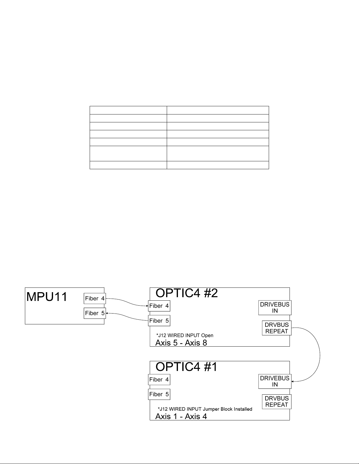
Two OPTIC4 interface cards can be connected to a MPU11 motion control card. The OPTIC4s will
negotiate their axis numbers based on the order they are connected. The last OPTIC4 in the communication
chain will initiate communication and start numbering axes at 1. LED1 will flash one segment at a time during
startup while the OPTIC4s determine their location in the communication chain. After about 10 seconds the
OPTIC4 for axes 1 - 4 will indicate 1 on LED1, and the OPTIC4 for axes 5 - 8 will show 5 on LED1. Once
LED1 stops blinking, startup negotiation is complete and normal operation begins.
LED1 normally indicates the base, or first, axis number on the OPTIC4. If the decimal point is lit, and a
number is flashing on LED1, this indicates an error condition that can be found in the “LED1 Error Codes”
section.
svn://software/optic4/trunk/docs/OPTIC4_MAN.flo MRR Page 1 of 6 8/6/2010
Page 2

Jumper Functions
Designator Jumper Name Function with jumper block in place Function with jumper block removed
J13 Enable Active
High
J12 Wired Input Communicate with another OPTIC4 over
J8 Fiber Repeat Drivebus out to another drive connects with
J10 Config Offset and gain trim - NEVER INSTALL
J9 Aux 1 Spare Spare
J11 Aux 2 Spare Spare
Enable outputs will pull down when axis is
released
wires (this OPTIC4 is not connected to
MPU11)
fiber optics (factory hardwired if all 4 fiber
connectors are installed)
THIS JUMPER
Enable outputs will pull down when axis is enabled
Communicate with MPU11 through fiber connectors
Drivebus out connects to another drive over wires
Normal operation
svn://software/optic4/trunk/docs/OPTIC4_MAN.flo MRR Page 2 of 6 8/6/2010
Page 3

Motor Brake Outputs
Open collector brake driver outputs are provided for each axis. These outputs may be used to
drive a relay to release axis brake solenoids. Note that the OPTIC4 has a built in diode to suppress transients
that should be connected to the relay coil positive supply. This feature does not eliminate the need for noise
suppression devices located close to the relay coil. Motor brake mechanisms may also require noise
suppression, such as a resistor and capacitor network for AC solenoids or a diode for DC solenoids.
Typical Brake Wiring Example
OPTIC4 Internal Circuitry
Brake Relay Driver Output
OPTIC4
RET URN
OPTIC4 Internal Circuitry
Enable and Auxiliary Outputs
5 to 24VDC
Output
Output
External Power Supply
5 VDC
5 COM
OPTIC4 Internal Ci rcuitry
E-stop / Fault Relay Output
External Power Supply
24 VDC
24 COM
Brake Release
Solenoid
E-st op Contact 1
E-st op Contact 2
OPTIC4
RET URN
svn://software/optic4/trunk/docs/OPTIC4_MAN.flo MRR Page 3 of 6 8/6/2010
Page 4

Fault Inputs
Fault inputs are provided for each axis. The input voltage may be from 5 VDC to 24 VDC, but all four
faults must operate from the same voltage. The SIP resistor pack (R69) must be appropriate for the input
voltage.
Typical Fault Input Wiring Example
Servo Drive Internal Circuitry
Fault or Alarm Relay
24 VDC
FAULT COMMON
OPTIC4 Internal Circuitry
Fa ult Input
SIP
24 COM
SIP Identification - XXX Indicates Value
4308R-102
-XXX
SIP Value Marking
471 470 5
122 1.2k 12
222 2.2k 24
SIP Input Voltage Selection
Resistor Value (Ohms) Input Voltage
FAULT IN
SIP Internal Wiring / Pinout
svn://software/optic4/trunk/docs/OPTIC4_MAN.flo MRR Page 4 of 6 8/6/2010
Page 5

OPTIC4 Specifications
Characteristic Min. Typ. Max. Unit
5 Volt Supply Current 0.5 - - A
12 Volt Supply Current 0.25 - - A
Open Collector Output Current - 10 90 mA
Open Collector Output Voltage - 5 25 V
Relay Output Current 0.1 - 10 A @ 125VAC
Relay Output Current 0.1 - 5 A @ 30VDC
Input Operating current 9 11 15 mA
Analog Output Resolution - 16 - bits
Analog Output Voltage -10 - 10 V
Analog Output Current 0 1 20 mA
Fiber 4 and 5 Length - - 100 feet
Size: 12 * 5 * 0.75 (W*D*H) Inches
OPTIC4 Troubleshooting
Symptom Possible Cause Corrective Action
+5V, +12V, or -12V LED not
lit
ENABLE LED not lit and no
error on LED1
Tach output is not stable and
has a square wave shape when
viewed on an oscilloscope
power connection to H1 is
faulty
power not applied to board see +5V, +12V, or -12V LEDs FPGA OK LED not lit
damaged OPTIC4 return for repair
Main enable off Check for errors in software
Encoder is bad - 'A'
channel duty cycle is not
50% at constant velocity
correct wiring or power supply
problem
preventing MPU11 from enabling
drives
Adjust encoder if possible, or replace
encoder
LED1 Error Codes
Error
Number
1 Communication
2 Not Used
3 Not Used
4 Not Used
5 Not Used
6 Not Used
7 Not Used
8 Not Used
9 Not Used
svn://software/optic4/trunk/docs/OPTIC4_MAN.flo MRR Page 5 of 6 8/6/2010
Meaning Cause Corrective Action
Failure
The OPTIC has lost
communication from the
MPU11
Make sure MPU11 is connected and
running. Check fiber 4 or wired
connection. Make sure "WIRED
INPUT" jumper is set properly.
Page 6

12.0"
(305mm)
(152mm)
11.4"
(290mm)
6.0"
OPTIC4 Connections and Mounting Footprint
5.0"
AUX 1 LED
FPGA OK LED
R69 SIP
RESISTOR
(127mm)
ENABLE LED
-12V LED
+12V LED
4.4"
(112mm)
LED1
+5V LED
POWER
Chassis Ground
BRAKE / E-STOP
AXIS 1
AXIS 2 AXIS 3
AXIS 4
DRIVEBUS
IN
E-stop Relay Contact 1
E-stop Relay Contact 2
Brake Relay Driver 1
Brake Relay Driver 2
Brake Relay Driver 3
Brake Relay Driver 4
Relay +5 to +24VDC
Tach Analog
Drive Analog
Tach Analog
Drive Analog
Tach Analog
Drive Analog
Tach Analog
Drive Analog
+5V
Return
Return
Enable
Return
Enable
Return
Enable
Return
Enable
+12V
Return
-12V
No Connection
No Connection
No Connection
No Connection
No Connection
No Connection
Return
Auxiliary Output
Fault In
Fault Common
Chassis Ground
Auxiliary Output
Fault In
Fault Common
Chassis Ground
Auxiliary Output
Fault In
Fault Common
Chassis Ground
Auxiliary Output
Fault In
Fault Common
Chassis Ground
Return
Receive +
Receive Transmit Transmit +
HIGH
WIRED
INPUT
ENABLE
ACTIVE
Configuration
Jumpers
ENCODER 4
N/C
Return
-Index
-A
-B
ENCODER 3
+Index
+A
+B
+5V
Fiber 4 to MPU11
Fiber 5 from MPU11
DRIVEBUS
OUT
ENCODER 1
ENCODER 2
N/C
Return
-Index
-A
-B
N/C
Return
-Index
-A
-B
Return
Receive +
Receive Transmit Transmit +
+Index
+A
+B
+5V
+Index
+A
+B
+5V
svn://software/optic4/trunk/docs/OPTIC4_MAN.flo MRR Page 6 of 6 8/6/2010
 Loading...