


Ajax Centroid CNC11 MPU11/GPIO4D
Installation Manual For Mill – Win 7
Last revised 2013-09-19 (277)


Table of Contents
1. Introduction
2. What's included
3. Order Of Installation
4. Desk/Benchtop connection, software and network installation and configuration
5. Mounting major components in electrical cabinet
6. Connecting and testing major components in the electrical cabinet
7. Wiring basic sub-systems
8. Configuring motors, encoders and limit switches in software
9. Wiring auxiliary sub-systems
9.1 Lube pump
9.2 Coolant pump
9.3 Spindle

Introduction
This manual describes how to install the Ajax CNC (Computer Numerical Control) system. It is
strongly recommended that you follow each step in order without skipping steps. The PC based
system provides up to 4 axes (upgradable to 8 axes) of closed loop servo interpolated motion,
controlled by industry standard G-Codes. The system is intended for CNC control of milling
machines, routers, lathes, flame, plasma, laser/water jet cutters, and other specialized applications.
This system is intended for to be installed by competent installers, retro-fitters, and machine tool
builders who want to do their own installation. This installation manual is not intended for casual
end users.
Before You Begin:
Installing your new Ajax CNC11 based GPIO4D System is a straight forward process if you follow
the directions included here. Before getting started, please take the time to familiarize yourself with
the schematics, manuals and installation instructions.
While doing the installation, it is very important that you follow the instructions exactly. Doing the
installation incrementally and testing as you go will allow you to immediately isolate the cause of
any problems that you may run into. A troubleshooting procedure is included for each section of
the installation so that if you do run into any problems, you will be able to quickly isolate the cause
and correct it. In addition tot he troubleshooting procedures you can find answers to many
questions in our support forum www.ajaxcnc.com/ajaxbb
If you run into a problem that you can not solve using the troubleshooting procedure or through the
support forum, please fill out the appropriate troubleshooting form included in Appendix A and send
it via email to tech@ajaxcnc.com. Fee based phone support is also available if needed. Please
see http://ajaxcnc.com/tech_support.htm for details.

2. What's included:
Make sure your kit is complete and has not been visibly damaged in shipment. The basic
GPIO4D kit includes:
The Ajax CNC11 Based CNC Kit you purchased contains: Qty
1. GPIO4D 4 axis 3rd party Servo Drive interface with integrated PLC 1 ea.
2. MPU11 Motion Controller 1 ea.
3. Fiber Optic Cable 2 ea.
4. +-12VDC, 5VDC Digital Power Supply 2 ea.
6. Power Cable - Digital PS to MPU11, GPIO4D 2 ea.
7. – 11. Connectors & Misc
8. Software Install & Documentation CD
FIG.2

3. Order Of Installation
Section 4 - Desktop/Bench top connection -
4.1 Connecting the major components
4.2 Power up for the first time
4.3 Software installation and configuration in Windows 7
4.4 Testing PC, MPU11 and PLC communications
Section 5 - Mounting, connecting major components in your electrical cabinet
Mount, connect and test PC, MPU11 and GPIO4D
Section 6 – Connect and test the major components in the electrical cabinet
Section 7 - Wiring Basic Sub-systems
7.1 Wiring limit switches and Estop PLC Input
7.2 Testing limit switches and Estop input
7.3 Wiring Estop coil
7.4 Wiring encoders
7.5 Testing encoders
7.6 Wiring motors and motor power
7.7 Testing motors and motor power
Section 8 - Configuring motors, encoders and limit switches in software
8.1 Configuring motors to move in the correct direction
8.2 Configuring encoders
8.3 Temporarily zero out limit and home switch PLC input values
8.4 Configuring your motors to move the correct distance
8.5 Configuring backlash compensation
8.6Configuring limit and home switches
Section 9 - Wiring Auxiliary Sub-systems
9.1 Lube pump
9.2 Coolant pump
9.3 Spindle
9.3.1 Reversing Contactors
9.3.2 VFD/Inverter Wiring – AutomationDirect GS2

4. Desk/Bench Top Connection & Software Install.
4.1 Connecting the major components The first step in the installation is to connect the major
components together on your desktop as depicted in Fig. 3 below. Be sure that your surface is
non-conductive and that you use a power strip so that all you components are powered on and off
at the same time. When everything is connected, your setup should look similar to the photo in
Fig. 4 on the following page. At this point, the only connections that should be made are:
a) The 110VAC from the power strip to the digital power supplies.
b) Connect the digital power cables to the MPU11 and GPIO4D
c) Shielded CAT5 network cable from the PC to the MPU11
Ajax recommends purchasing the blue Cat5e shielded F/UTP snag-less patch cables from
StarTech, StarTech ID # S45PATCH25BL.
d) Fiber optic cables (2) from the GPIO4D to the MPU11
A
B B
D
FIG.3
Shielded CAT5
C

4. Desk/Bench Top Connection & Software Install. (cont)
4.2 Powering up for the first time With the major components all connected, confirm that all
components are resting on a non-conductive surface and turn on your power strip to power up your
components and PC. While powering up, you notice that there are 4 LED's next to the power
connector (see yellow rectangle below) on the MPU11 that flicker while the MPU11 is initializing.
After 15-30 seconds the LED's should be in the following states:
FPGA-OK = Solid green
DSP Debug = Flashing ~1 per sec
DSP -OK = Solid Green
+5V = Solid Green
FIG.4
4. Desk/Bench Top Connection & Software Install. (cont)
4.3 Software Installation and configuration on Windows 7 With your desktop
configuration completely powered up as described in section 4.2. Install the CNC11
Software and configure Windows to communicate with the MPU11
4.3.1 Obtaining and installing the latest CNC11 Software version
The Centroid CNC11 software can be found in the “Centroid CNC11 Software” directory on
the DVD supplied with all Ajax MPU11 systems is also available for download* from the
AjaxCNC website at: http://ajaxcnc.com/tech/downloads/software/. It is recommended that
check to make sure that you have the latest CNC11 version before installation.
If you are running from the DVD, double click “setup.exe” in the “Centroid CNC11 Software”
directory to begin the software installation. (If you downloaded the software from the
website, extract the files to a local directory and then run “setup.exe” from “Centroid CNC11
Software” directory).
When the installer begins, you will be presented with a list of checkboxes to select which
package – Mill, Lathe, Mill Demo or Lathe Demo. Select only “Mill” and click “next”. When
prompted for the installation drive, leave it at the default location (c:\), click “next”. When the
CNC11 installation is complete, click “Next” and then “Finish”.
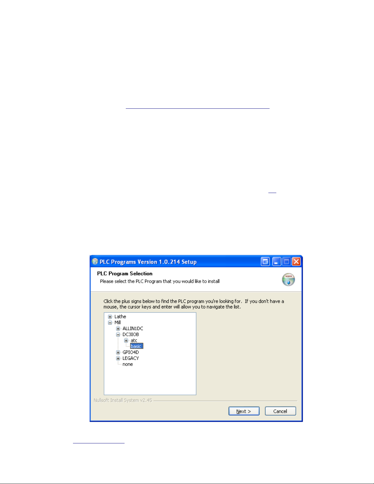
4.3.2 Installing a PLC program After the CNC11 software has been installed, the installer
will prompt you to install a PLC program, select “Yes”. Click on the “+” signs next to Mill &
GPIO4D and then click on “basic” under Mill->GPIO4D to select it and click “Next” and then
“Finish” to complete the CNC11 and PLC software installation.
*Requires username and password to access link. If you do not know your username and password, please
email tech@ajaxcnc.com to request it. When emailing, be sure to provide the customer name and address
that your MPU11 system was purchased under or your system serial number. We cannot process your request
without this information.

4. Desk/Bench Top Connection & Software Install. (cont)
4.3.3 Configuring Windows 7 and Your PC Hardware To Run CNC11
Before running CNC11 software for the first time, you must first configure Windows XP and
your PC hardware to allow communications with the MPU11 hardware. This involves
configuring the IP address of your network adapter and configuring Windows firewall to allow
CNC11 access to the network to communicate with the MPU11 hardware.
4.3.3.1 Configuring Ethernet card to Communicate with the MPU11
Configuring the network card in your PC to communicate with the MPU11 motion control
card. There are a couple things to note before we get started. All MPU11 systems will be
networked with a static IP network. You will need a second network card for networking your
control to a remote PC for file transfer. The NIC (Network Interface Card) in your PC and the
MPU11 motion card have dedicated IP addresses:
CNC11 PC : 10.168.41.1
MPU11 card : 10.168.41.2
Before you run the CNC11 software in Windows you need to configure the NIC to
communicate with the MPU11. For Windows 7 click on the Start Menu → Control Panel →
Network Connections. From the Network Connections window right click on the on board
NIC highlight TCP/IP and select properties.
Check the “Use the following IP Address” and set the fields.
IP Address : 10.168.41.1
Subnet Mask : 255.255.255.0
Leave the Default Gateway blank and click OK.
4.3.4 Configure Windows Firewall To Allow CNC11 to Communicate With The MPU11.
Double click the CNC11 Mill icon on your desktop to start the CNC11 software. Depending
on your Windows Firewall configuration you may see the window below when you first try to
run CNC11. You must click “Unblock” to allow CNC11 to make changes to your computer in
order for CNC11 to operate correctly.

4. Desk/Bench Top Connection & Software Install. (cont)
4.4 Testing PC and MPU11 communications.
If you have followed the instructions up to this point, you should be looking at the
screen below. Congratulations! You have just confirmed that the PC and MPU11 are
communicating correctly.
Now, Press F10 (Cont) to enter the main screen of CNC11. Don't be alarmed that you don't
see numbers in the DRO, we'll get to that later in section 6.3 when we wire the encoders.
CNC11 Main Screen
Select “Shut Down” (F10) then “Exit CNC11” (F9). Power off the computer and turn
off power to the MPU11 & GPIO4D at the powerstrip/

4. Desk/Bench Top Connection & Software Install. (cont)
4.5.1 Getting Ready To Test PLC Inputs and Analog outputs to drives:
IMPORTANT: – The analog outputs to the servo drives will be DISABLED if ANY of the
Fault, Limit, Estop or Drive Fault inputs are open OR a stall or encoder fault is
detected.
Before you can test the PLC and drive interface, you must first jumper the Faults, Limits,
Estop and Enable PLC Inputs and disable encoder faults and stall detection in the
software. When this section of testing is complete, leave any fault, limits or encoder inputs
which are not being used being used jumped and/or disabled in software.
4.5.2 Inserting the correct SIPS for testing. SIPS (Single Inline Package) are resistor
packs which configure the PLC inputs for use with a specific voltage. The GPIO4D can be
configured for use with +/- 5VDC, +/- 12VDC or +/- 24VDC devices. For testing purposes,
we will be using the +12VDC and 12 Com power which are available on the power header
(H6) on the GPIO4D. Before testing however, we'll need to install the correct SIPS (1K)
resistors on the PLC inputs.
Before changing SIPS -MAKE SURE THE GPIO4D & MPU11 ARE POWERED OFF!!!
The SIPS are located just behind the input headers (H9 & H10) and each SIP determines
the voltage for a bank of 4 inputs. Values and input voltages are as follows:
470 Ohm SIP = 5 VDC input
1K Ohm SIP = 12VDC input
USE 1K FOR TESTING!!!
2.2K Ohm SIP = 24VDC input
NOTE: The SIPS do not need to be oriented in any particular way when inserted in the
socket.

4. Desk/Bench Top Connection & Software Install. (cont)
4.5.2 Jumping Faults, Limits, Estop and Enable Inputs: In order to test I/O
communications while on the benchtop, install jumpers on the following inputs:
Drive Fault Inputs: Inputs 17-20
Limit Switch Inputs: Inputs 1-8
Lube Fault input: Input 9
Spindle Fault Input: Input 10
Emergency Stop Input: Input 11
NOTE: Jumpers should be left on any Limit switch inputs or fault inputs which will not be
used.

4. Desk/Bench Top Connection & Software Install. (cont)
4.5.3 Disabling encoder faults and disabling Stall Detection for testing With the
jumpers installed as shown in figure 5 of the previous page, power up the MPU11 &
GPIO4D simultaneously by turning on the powerstrip. After giving the MPU11
approximately 30 seconds to initialize, start the CNC11 software by double clicking on the
“CNC11 Mill” icon on your desktop.
To disable the encoder faults, set parameters 308-315 to 0 and press F10-Save to save
the settings. To enter the parameters screen:
From the main screen – F1-Setup->F3 -Config (pw = 137)->F3 Parms. Once in the
parameters menu use F7 & F8 to navigate between screens.
Disabling Stall Detection To disable Stall Detection, go into the PID screen as described
below and press the “Ctrl” and “V” keys simultaneously to toggle Stall Detection on and off –
Make sure it displays “Stall Detection Disabled” as displayed below
From the main screen – F1-Setup->F3 -Config (pw = 137)->F4 PID

4. Desk/Bench Top Connection & Software Install. (cont)
4.5.4 Confirming jumper wiring and parameter settings Use the escape key to navigate
back to main screen from the parameter menu and then press “alt” and “i” keys to to bring
up the real-time I/O display as shown below. (pressing alt -i again will turn off the I/O
screen).
When you press Press F3 -MDI, notice that outputs 17-20 light up. These are the enable
outputs to the servo drives. If the enable outputs do not light up, check that inputs 1-11 and
17-20 are green as displayed above. If they are not, double check your wiring and your
SIPS. If the above inputs are all green and you still don't have enables – double check your
encoder parameter settings. For ANY of the above mentioned inputs, when an input is
open the display state for that input will be red and a fault, limit or estop will be
detected and MOTION DISABLED. When an input is closed the display state for that
input will be green and, if no other faults exist, motion will be enabled.
4.5.5 Testing Limit Switch Inputs Disconnect and connect the jumpers from the limit switch
inputs (inputs 1-8) and confirm that the states on the realtime I/O screen change to red when
the jumper is removed and back to green when the jumpers are installed. NOTE: For the
time being, all the limit switch inputs MUST remain for further testing purposes.
4.5.6 Testing Estop input Disconnect and
connect the jumper from the emergency stop
input (input11) on the GPIO4D and confirm that
Emergency stop detected/released message
toggles as show here.

4. Desk/Bench Top Connection & Software Install. (cont)
4.5.7 Testing Drive Fault Inputs Disconnect and connect the each of the drive fault inputs
(inputs 17-20) and observe that the correct message is displayed for each drive fault input.
When input 17 is open (remove wire from FLT on H14) “Axis1 Drive Fault Detected” should
be displayed. When input 18 (remove wire from FLT on H13) “Axis2 Drive Fault Detected”
should be displayed and so on... Drive faults, Lube fault and Spindle faults require that the
Estop input be cycled (jumper removed and re-connected) to clear the fault condition after
the drive fault jumper has been re-connected. NOTE: For the time being, all the Drive Fault
inputs MUST remain for further testing purposes.
4.5.8 Testing the Spindle and Lube Faults Disconnect and connect the Spindle Fault input
(input 10) and the Lube Fault input(input 9) and observe that the correct messages is are
displayed for each. Don't forget to cycle the Estop input in between to clear the previous
fault. NOTE: For the time being, Spindle and Lube Fault inputs MUST remain for further
testing purposes.
4.5.9 Testing Analog Outputs To The Servo Drives Press F3-MDI to bring up a
command prompt. This will enable the drives (Out17-20). If you followed the procedures
outlined in sections 4.5.1-4.5.8, your I/O states for the output enables and the inputs for the
the Limits, Estop Spindle, Lube and Drive Faults should look exactly as shown below
(inputs 1-11, 17-20 and outputs 17-20 should be green)
If any of the above mentioned inputs or outputs are not green, please review the procedures
in sections 4.5.1–4.5.8 to look for missed steps.
If inputs 1-11, 17-20 and outputs 17-20 are green, and you have disabled stall detection as
described in section 4.5.3, you should now be able to command a move on an axis in MDI
and read a 0-10VDC analog voltage across the Analog Out and Analog COM terminals for
that axis. (NOTE: It will immediately jump to +10 or -10 because the motors/encoders are
not responding) command a move in the opposite direction to change the polarity of the
output.

5.Connect major components in your cabinet
Connect the major components in your electrical cabinet just you had done on your desktop in
section 4 but wire your 110VAC service through your cabinet disconnect instead of a power strip.
a) Connect the 110VAC from the disconnect to the GPIO4D & MPU11 power supplies
b) Connect the digital power cable from the MPU11 power supply to the MPU11
Connect the digital power cable from the MPU11 power supply to the GPIO4D
c) Connect the Shielded CAT5 network cable from the PC to the MPU11
d) Fiber optic cables (2) from the GPIO4D to the MPU11
A
B B
D
C
Power up and test the system as described in section 4 but omit the software installation process.

6. Wiring Basic Sub-systems
6.1 Limit switch and Estop PLC input wiring Limit switches on the GPIO4D should
be a normally closed type switch (contact closure). Use of normally open switches
requires a custom PLC program that can be supplied by the customer or purchased from
AjaxCNC. For the purposes of this document, all limit and estop inputs are assumed to
be normally closed.
Connect your limit switches as shown:
Connect your Estop switch as shown: (no pendant)
6. Wiring Basic Sub-systems (cont)
6.1 Limit switch and Estop PLC input wiring (cont)
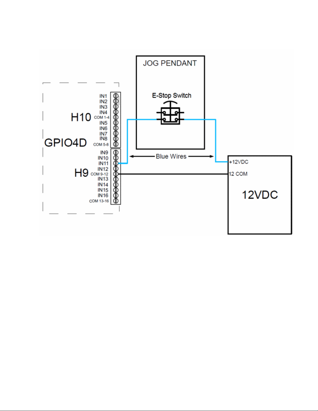
Connect your Estop switch with pendant

6. Wiring Basic Sub-systems (cont)
6.2 Limit switch and Estop PLC input testing Power up your system to test the limit
switch and Estop PLC input wiring. Start the CNC11 software by double clicking on the
CNC11 Mill icon on your desktop. After the MPU11 has initialized, press F10 to continue
to the main screen. Now, hold down the “alt” key and press the “i” key at the same time
to bring up the real-time I/O display.
The image above shows the limit switches, inputs 1-8, in the normally closed and
operational state. The EstopOk input(input 11), the LubeOk (input9) and
SpindleInverterOk (input10) are also in the normally closed and operational state.
Trip your Estop and limit switches individually and confirm that the display changes from
green to red and then back to green when you trip and release each switch that you
have wired. Confirm that, when none of the limits are tripped, ALL limit switch inputs (1-
8) MUST be green. If they are not, please check your limit switch wiring or review
section 4.4.2 to defeat your unused limit switch inputs. Confirm also that the Estop input,
input 11, is green when the switch is not tripped.
Power off your system and continue to section 6.3 “Encoder Wiring”

6. Wiring Basic Sub-systems (cont)
6.3 Encoder wiring Wire the db9 connector that connects your encoders to the MPU11
as shown below:
NOTE: On 3rd party drive/motor systems, in addition to the incremental encoder feedback
there will also often be Tach and/or commutation channels being returned from the
motors. The MPU11 requires only the encoder channels listed above and does not use
the Tach or commutation channels.
When you have completed wiring your encoder cables, connect them to the MPU11 as
shown below and continue to section 6.4 “Testing Encoder Wiring”
Z axis
Y axis
X axis
6. Wiring Basic Sub-systems (cont)
6.4 Testing Encoder Wiring Power up your system to test the encoder wiring. Press
the Estop button in keep it there. Start the CNC11 software by double clicking on the
CNC11 Mill icon on your desktop. After the MPU11 has initialized, press F10 to continue
to the main screen. From the main screen press:
F1 -Setup → F3 Config, password = 137, Press enter → F4 PID
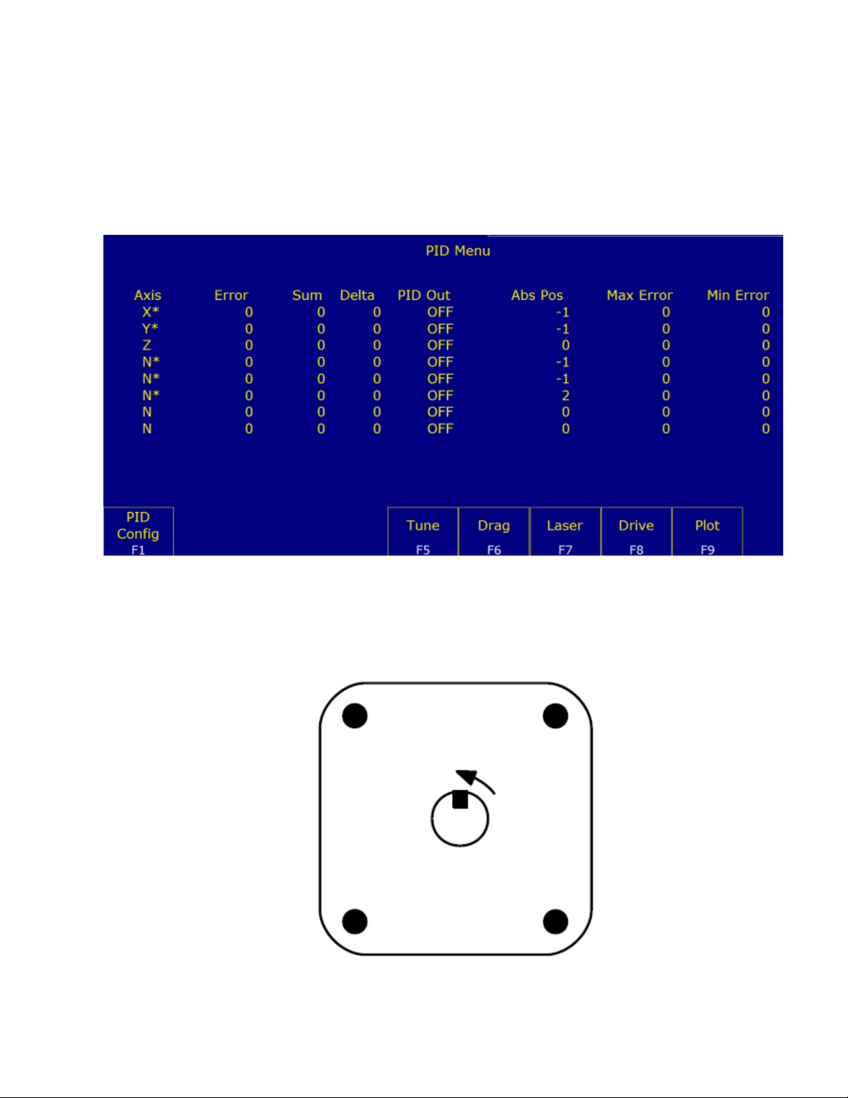
This will display the PID screen below and allow you to monitor the encoder counts by
watching the values in “Abs Pos” for each axis.
6.5 To confirm that each encoder is wired correctly, rotate the motor shaft CCW (as seen
while looking at the face of the motor as shown below) and confirm that the position
displayed in the ABS Pos becomes more positive while rotating the shaft CCW and
becomes more negative rotating the shaft CW:
Motor face plate
Rotating the shaft CCW increases
the value in the Abs Pos field
For each axis, note the value of “Abs Pos”, rotate the motor shaft exactly 1 revolution and
note the new ABS Pos. Subtract the two and write down this value. This is the number of
encoder counts per revolution of the motor. We will use this value in section 8 when
configuring your motors.
6. Wiring Basic Sub-systems
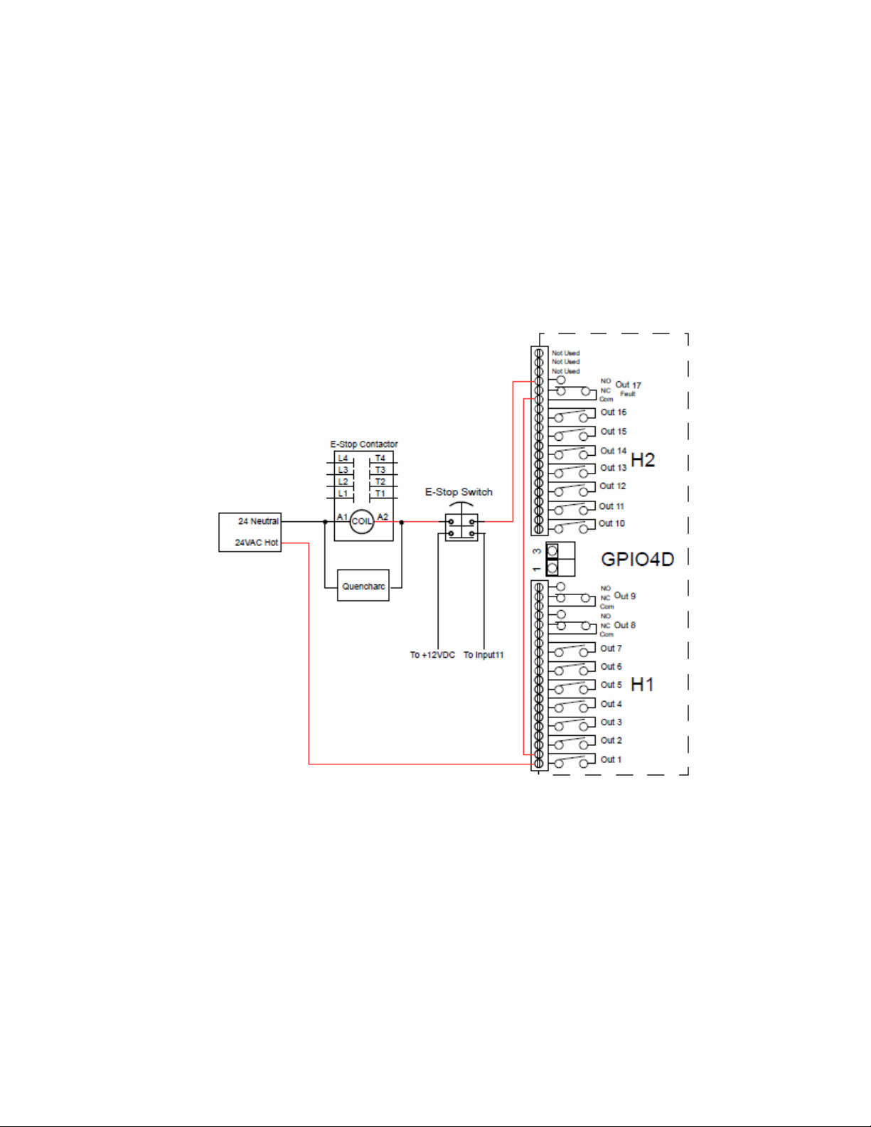
6.6 Wiring the Estop Coil The coil voltage that controls the Estop contactor is routed
through your Estop switch and two fault relays on the GPIO4D. The first relay (Output1)
is controlled by the PLC program and can be used to drop the Estop contactor based on
any PLC event. The second relay (Output17) is used to drop the Estop contactor in the
event that a fault occurs that the PLC is not be able to recognize – such as a hardware
communication error between the GPIO4D and the MPU11. The Estop switch and fault
relays are wired in series so that, if any of the circuits is opened the Estop contactor is
dropped out. The drawings below route 24VAC to the coil of the Estop contactor but the
coil on your contactor may use a different voltage. If that is the case, simply substitute
your supply voltage for the 24VAC shown in the drawings.
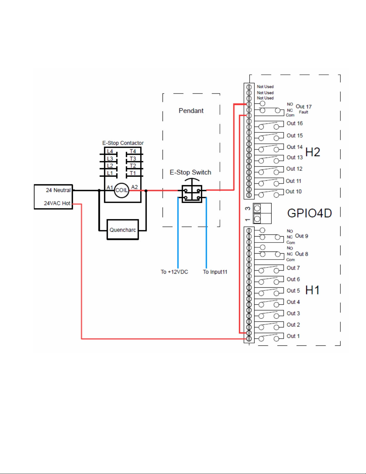
6. Wiring Basic Sub-systems
Estop coil circuit with pendant
6.7 Testing Estop Coil Wiring Power up your system to test the etop contactor wiring.
Start the CNC11 software by double clicking on the CNC11 Mill icon on your desktop.
After the MPU11 has initialized, press F10 to continue to the main screen.
Press your Estop switch in and then release it Observe the estop contactor engages
when the Estop switch is released and disengages when Estop is pressed.
Power off the system and proceed to section 7.1 “Wiring 3rd Party Servo Amplifiers to the
GPIO4D ”
7. Wiring 3rd Party Servo Amplifiers to the GPIO4D
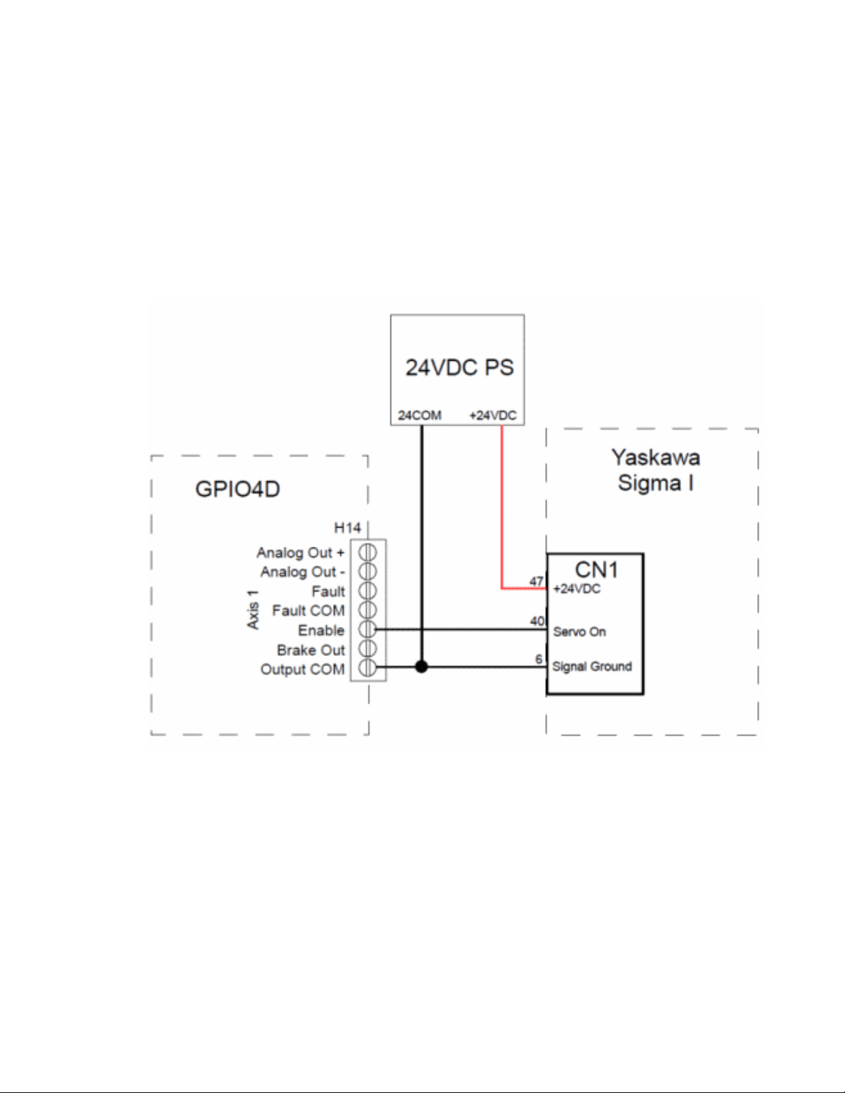
7.1 Wiring Enables from the GPIO4D to your 3rd Party Servo Amplifiers. The GPIO4D
provides an “active low” enable to 3rd party Servo amplifiers. This means that, when the
GPIO4D enables an axis, it will pull the signal level of enable output pin down to 5VCOM. If
your 3rd 3rd party Servo Amplifiers require an “active high” enable, you will need to wire it
through an external 5VDC relay or use a PLC output*
*Wiring the enable through a PLC output requires a custom PLC program. An example
is PLC program that peforms this function is available on the AjaxCNC support forum
under the topic: “Current Versions Of Standard MPU11 PLC Programs“

7. Wiring 3rd Party Servo Amplifiers to the GPIO4D (cont)
7.2Wiring GPIO4D External Drive Fault Input The GPIO4D will detect an external drive
fault if the Fault input and Fault COM are not connected to a DC supply voltage and its
opposite. For instance, if the FaultCom is connected to +5VDC, the Fault input must be
connected to 5COM. Which is connected to which does not matter as long as they are
connected to the opposite of each other. I.e. if the Fault input is connected to +24VDC,
the Fault COM must be connected to 24COM or an external drive fault will be detected
the axis will be disabled by the GPIO4D.
7.3 Wiring GPIO4D Analog Control Voltage If no faults are detected, the GPIO4D
provides -10 to +10VDC for analog control of up to 4 3rd party servo amplifiers. When
wiring the analog control voltage -always- use twisted pair wiring between the GPIO4D
and the servo amplifier.

8. Configure motors, encoders and limit in software
1. Configure your servo amplifiers for velocity mode and check the PID values in
CNC11 BEFORE testing motor movement.
2. Do NOT try to move your motors until instructed to do so below.
8.1 Configuring PID parameters in CNC11 Before powering up the system, push your
Estop switch in and leave it in. Power up your system. Start the CNC11 software by
double clicking on the CNC11 Mill icon on your desktop. After the MPU11 has initialized,
press F10 to continue to the main screen. Navigate to the PID Config screen as follows:
F1-Setup->F3-Config (pw=137)->F4 PID->F1-PID Config
Set the PID for all axes as shown:
Kp = .01 Ki = .00004 Kd = 0 Limit 256000 Kg = 0 Kv1 = 40 Ka = 0 Accel = .500
8.2 Re-enable encoders and stall detection in software To enable your encoders, set
parameters 308-312 to 1-4 (or set 308-311 to 1-3 if you only have 3 axes) and press
F10-Save to save the settings. To enter the parameters screen:
From the main screen – F1-Setup->F3 -Config (pw = 137)->F3 Parms. Once in the
parameters menu use F7 & F8 to navigate between screens.
8.3 Enable Stall Detection To enable Stall Detection, go into the PID screen as
described below and press the “Ctrl” and “V” keys simultaneously to toggle Stall Detection
off – Make sure it no longer displays “Stall Detection Disabled” belwo the status window
From the main screen – F1-Setup->F3 -Config (pw = 137)->F4 PID

8. Configure motors, encoders and limits in software (cont)
8.4 Confirm Encoder Feedback on all axes With the Estop pushed in, manually rotate
each motor and confirm that you have smooth feedback on all axes and that X updates the
X DRO, Y updates Y DRO etc... If any of your encoders do not update as expected, please
review the encoder parameters above (sec 8.2) and/or encoder wiring and MPU11
connection in section 6.3. If all your encoders update smoothly, manually move all axes to
the center of their travel to provide safe clearance when the motors are tested under power.
8.5 Release Estop and use MDI to manually set home Carefully release the Estop
switch, being ready to press it again quickly if unexpected movement occurs. Press F3MDI and you should see the MDI prompt. If it immediately exits, you have a fault. Look
in your status window for the cause of the fault and refer to appropriate previous sections
in this manual to fix the problem that is causing the fault.
If the MDI prompt remains visible enter M26 /x/y/z Then press the cycle start key, or
simultaneously press “alt” and “s” keys. This will display numbers in the DRO's
Note: If you have additional axes to home, add another / and the label(s) as shown
below before pressing Cycle Start
8.6 Configuring movement Confirm that the feedrate override is set to 100% and enter
the following command in MDI:
Remember -be ready to press Estop if unexpected/violent movement occurs
G92 X0 Y0 Z0 Then press Cycle Start or press alt-s
When the DRO displays 0's for all 3 axes, enter this command in MDI:
G1 X.1 F1 Then press Cycle Start or press alt-s
If the move completes normally, command it to return to zero as shown below:
G1 X0 F1 Then press Cycle Start or press alt-s
Increase the distance to X1 and the feedrate to F10 and command the moves again.
Perform these moves for all axes.

8. Configure motors, encoders and limit switches in software
8.6.2 Configuring motors to move in the correct direction It is important to
understand that correct motor direction is determined by the motion of the tool relative to
the part, this is not necessarily the same as the motion of the table. For axes that move
the table while the tool remains stationary such as the X & Y axes on a typical Bridgeport
type knee mill, the table motion is the opposite of the “tool motion”. For axes that move
the tool, such as the quill on a knee mill, axis motion is the same as the tool motion. The
illustrations below describe this concept.
Correct tool motion for each axis
Difference between table motion and tool motion on X axis of knee mill
In the above illustration, the tool is moving in the X+ direction relative to the part
while the table moves to the left.

8. Configure motors, encoders and limit switches in software
Configuring motors to move in the correct direction (cont.) Use MDI to move each axis
and determine if the axis is moving in the correct direction. To determine this, observe that
the DRO counts more positive while moving an axis in the positive direction and that it
counts more negative while moving in the negative direction. To correct for an axis that is
moving in the wrong direction:
Press F1 -Setup → F3 Config, password = 137, Press enter → F2 Mach → F2 Motor
Use the arrow keys to select the “Dir Rev” field for the axis that needs to be corrected
and press the space bar to toggle it's current state.
8.6.3 Configuring encoder counts/rev Use the arrow keys to the “Encoder counts/rev”
field for each axis and enter the number of encoder counts per revolution of the the
motor that you wrote down in section 6.5

8. Configure motors, encoders and limit switches in software
8.6.4 Configuring your motors to move the correct distance Configuring your
motors to move the correct distance involves calculating the number of motor revolutions
required to move 1”. Prior to this step, you must have correctly configured your encoder
counts per motor revolution as determined in section 7.5 and entered in section 8.2.
To determine your motors revs/inch, set up a block on the table. Use a standard or
anything that you can accurately measure, a 6” parallel works nicely as shown below:
1. Jog in slowly from 1
direction to take up lash
2. Zero indicator and axes
3. MDI Z to .5” to clear
4. MDI command X to 6”
5. Read indicator to measure
distance traveled
6. Compute and enter new
motor revs/inch
Set X0, Y0, Z0
Spindle
Block measured 6”
How to compute motor revs/inch:
Commanded distance / Distance moved = multiplier
Multiplier * Current revs/inch = corrected revs/inch
Ex: Commanded Distance = 6.0000” = .99400~ (multiplier)
Distance moved = 6.0036”
.99400 * 5.0000 = 4.97000 New motor revs/inch
To change your motor revs/inch:
Press F1 -Setup → F3 Config, password = 137, Press enter → F2 Mach → F2 Motor
After you have made your changes, start again at step #1 above to confirm the new settings.
You should be able to accurately position to within a .0001 or so after performing this
procedure 1 or 2 times.

8. Configure motors, encoders and limit switches in software
8.6.5 Configuring backlash compensation A note on backlash and backlash
compensation: Before configuring the backlash compensation in the control, every effort
should be made to reduce the mechanical lash in your machine to less than .001”. The
“electronic” backlash compensation provided by the control will help, especially in point
to point moves, but the overall accuracy of your machine is determined purely by the
amount mechanical lash in the machine.
NOTE: Before measuring backlash, make sure any existing backlash compensation is
removed. As shown below, always use MDI and slow feedrates when measuring
backlash. If you jog or using faster feedrates, your measurements may be inconsistent
due to the inertia of the table.
1. Zero indicator and axis
2. MDI G1 X- .025 F.5
3. MDI G1 X0 F.5
4. Read indicator to measure
backlash
Spindle
5. Enter backlash amount
To enter backlash compensation values:
Press F1 -Setup → F3 Config, password = 137, Press enter → F2 Mach → F2 Motor
8.7 Configuring limit switches Use the escape key to go to the main screen. Confirm
that all axes now move in the correct directions, if any do not, perform the procedures in
section 8.6.2 again. When all axes are moving in the correct directions, jog all axes to
the middle of their physical travel and press the “alt” and “i” keys simultaneously to
display the real-time I/O screen. For each axis:
Trip a limit on an axis -if you tripped the + limit, it should only let you move the opposite
(minus). If it lets you move positive while the plus limit is tripped - your limit is setup
incorrectly in software. If the limit is setup incorrectly in software, switch the limit and
home inputs for that axis in motor configuration:
F1 -Setup ->F3 Config (pw=137)->F2- Mach-> F2 Motor
For instance, if the limits and home for the axis in question are currently 1 for – and
2 for +, change it to 1 for + and 2 for – under limits and home.
When you have done this for all axes and confirmed that the limit switches are configured
correctly in software, motion and limit configuration is complete
Power off the control

9. Wiring Auxiliary Sub-systems
9.1Lube Pump Wiring

9. Wiring Subsystems
9.1 Lube Pump Wiring The example uses the standard 110vac Lube Pump.
LUBE PUMP SUBCIRCUIT
The typical lube pump circuit
consists of two parts: The first part
is the control of the lube pump itself
which is controlled by output 2
sending 110VAC to the lube pump.
The second part is the low lube
alarm signal which gets wired to
input 9. The low lube signal tells the
control to produce a “405 Low lube”
alarm which inhibits the control from
starting a new job until the lube
pump is refilled and the alarm is
cleared.
When wiring your lube pump it is
important to know which type of lube
pump you have so that you configure
it correctly. Typically lube pumps
come in one of 3 types:
The Mechanical Cam Actuated Lube
Pump is based on a simple
mechanical plunger riding on a clock
motor driven cam. The advantage of
this type of lube pump is that it is
reliable and it remembers where it
was and how much run time has
been accumulated even between
power cycles. So that you actually
get lube ever 10 minutes for 5
seconds of machine use.
Electronic Lube Pumps try to imitate the mechanical cam pumps but often forget where in sequence they were
when powered off. There are two types of Electronic lube pumps, “lube first” which pumps lube immediately
after power on. Which typically results in too much lube. The second type is “lube last”, this type waits a set
amount of time before lubing the machine. The problem with is type is on small jobs your machine may never
get any lube, therefore possible damaging the machine. To avoid this some people wire the lube last type to
get power all the time which then results in too much lube.
Direct controlled lube pumps are controlled by the control via the PLC program and the software. With this
type the lube pump is not responsible for the timing of the pump actuation. This method is the best for reliable
even lubing of your machine. Centroid Users see Tech Bulletin #171 and Parameter 179 in the operators
manual for further explanation.

9. Wiring Auxiliary Sub-systems
9.2Coolant Pump Wiring
Coolant Flood Pump Sub-circuit Diagram
This sub-circuit shows how to hook up a 3 phase Flood Pump. Because the
pump draws higher current at 220V a Flood Contactor PART# 3959 is
needed. Notice the Quencharc PART# 1819 on the coil of the contactor, this
prevents electrical noise when the coolant flood is cycled on and off. A
thermal overload is also shown, this part protects the motor by opening the
circuit if it stalls for any reason, such as dips in the pump.
NOTE: This diagram depicts the 24VAC wired through the NC contacts on
the overload section of the contactor. The overload protection circuit on your
existing contactor may be labeled differently or there may be no overload
protection.
9. Wiring Auxiliary Sub-systems
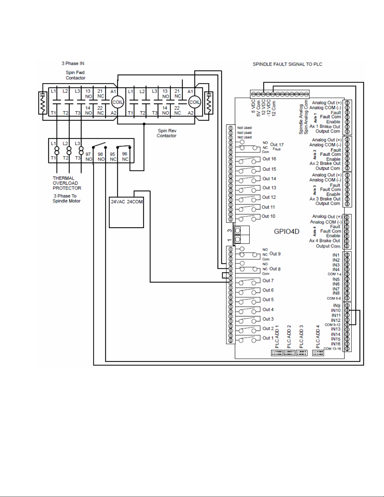
9.3 Spindle Wiring
9.3.1 Spindle Contactor Wiring
9. Wiring Auxiliary Sub-systems
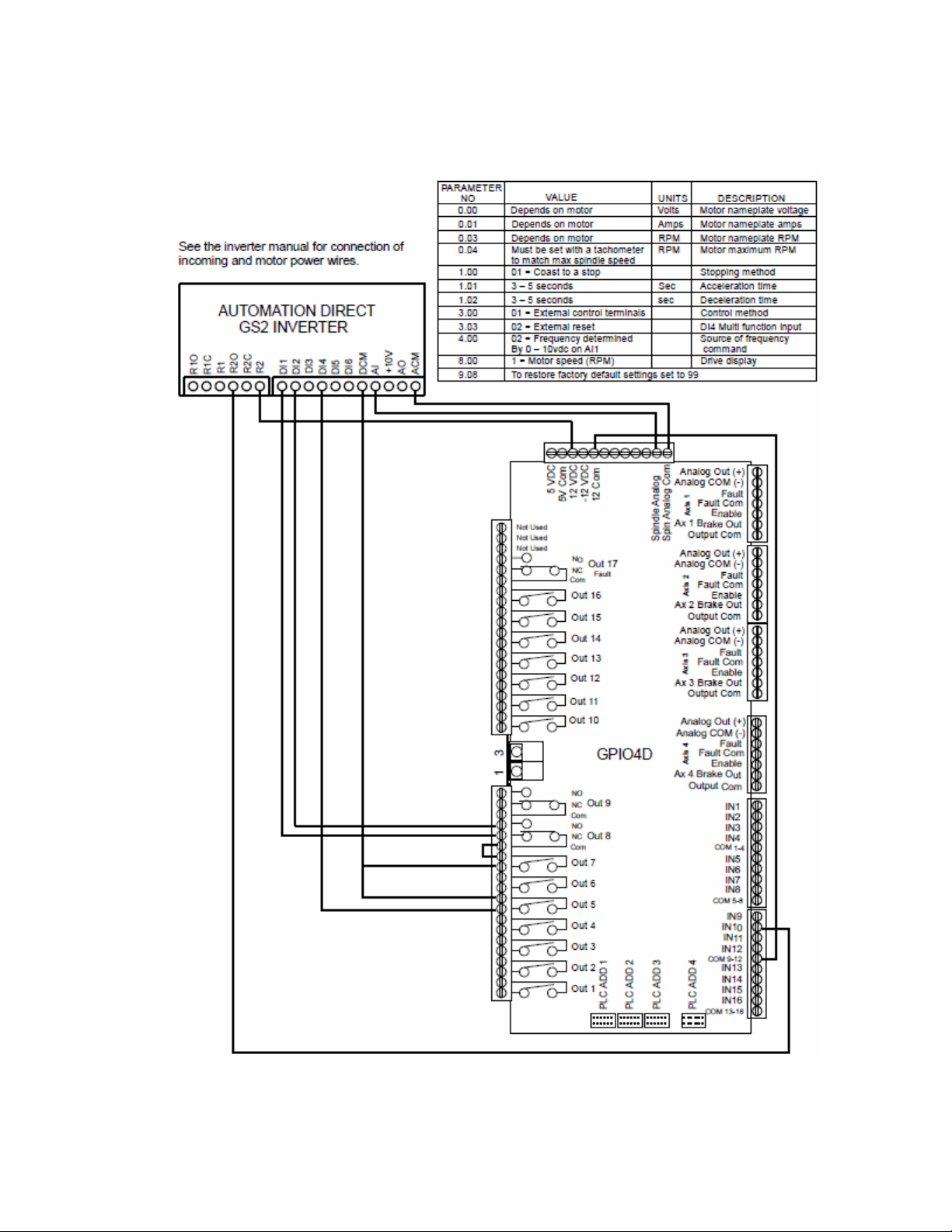
9.3.2 Spindle Inverter Wiring -AutomationDirect GS2
 Loading...