

AJA RH10UC User Manual [en, de, es, fr, it]

www.aja.com
Installation and Operation
Guide
Because it matters.
RH10UC
SD to HD Upconverter
R-series Card Module
Published: 7/13/10

2
Trademarks
AJA
trademarks of AJA Video, Inc. HDMI, the HDMI logo and High-Definition Multimedia Interface are trademarks
or registered trademarks of HDMI Licensing LLC. DVI is a registered trademark of DDWG. All other trademarks
are the property of their respective holders.
Notice
Copyright © 2010 AJA Video, Inc. All rights reserved. All information in this manual is subject to change
without notice. No part of the document may be reproduced or transmitted in any form, or by any means,
electronic or mechanical, including photocopying or recording, without the express written permission of
AJA Inc.
Contacting Support
To contact AJA Video for sales or support, use any of the following methods:
180 Litton Drive, Grass Valley, CA. 95945 USA
Telephone: 800.251.4224 or 530.274.2048
Fax: 530.274.9442
Web: http://www.aja.com
Support Email: support@aja.com
Sales Email: sales@aja.com
When calling for support, have all information at hand prior to calling.
®
, KONA
®
, Ki Pro®, and XENA
®
are registered trademarks of AJA Video, Inc. FiDO™, Io HD
™
and Io
™
are
Limited Warranty
AJA Video warrants that this product will be free from defects in materials and workmanship for a period of
five years from the date of purchase. If a product proves to be defective during this warranty period, AJA
Video, at its option, will either repair the defective product without charge for parts and labor, or will provide
a replacement in exchange for the defective product.
In order to obtain service under this warranty, you the Customer, must notify AJA Video of the defect before
the expiration of the warranty period and make suitable arrangements for the performance of service. The
Customer shall be responsible for packaging and shipping the defective product to a designated service
center nominated by AJA Video, with shipping charges prepaid. AJA Video shall pay for the return of the
product to the Customer if the shipment is to a location within the country in which the AJA Video service
center is located. Customer shall be responsible for paying all shipping charges, insurance, duties, taxes, and
any other charges for products returned to any other locations.
This warranty shall not apply to any defect, failure or damage caused by improper use or improper or
inadequate maintenance and care. AJA Video shall not be obligated to furnish service under this warranty a)
to repair damage resulting from attempts by personnel other than AJA Video representatives to install, repair
or service the product, b) to repair damage resulting from improper use or connection to incompatible
equipment, c) to repair any damage or malfunction caused by the use of non-AJA Video parts or supplies, or
d) to service a product that has been modified or integrated with other products when the effect of such a
modification or integration increases the time or difficulty of servicing the product.
THIS WARRANTY IS GIVEN BY AJA VIDEO IN LIEU OF ANY OTHER WARRANTIES, EXPRESS OR IMPLIED. AJA
VIDEO AND ITS VENDORS DISCLAIM ANY IMPLIED WARRANTIES OF MERCHANTABILITY OR FITNESS FOR A
PARTICULAR PURPOSE. AJA VIDEO’S RESPONSIBILITY TO REPAIR OR REPLACE DEFECTIVE PRODUCTS IS THE
WHOLE AND EXCLUSIVE REMEDY PROVIDED TO THE CUSTOMER FOR ANY INDIRECT, SPECIAL, INCIDENTAL OR
CONSEQUENTIAL DAMAGES IRRESPECTIVE OF WHETHER AJA VIDEO OR THE VENDOR HAS ADVANCE NOTICE
OF THE POSSIBILITY OF SUCH DAMAGES.

Features
AJA RH10UC SD to HD Upconverter User Manual
•
Full 10-bit broadcast quality SD to HD upconverter mode of operation
•
HD Framesync mode of operation
•
8/10 bit SMPTE 259 SDI input, 2 re-clocked outputs
•
8/10 bit SMPTE 292 HD-SDI output, 4 outputs
•
8 Channels of Embedded SDI Audio are supported in Upconvert mode
(audio is not supported in HD Framesync mode)
•
bi/tri-level sync genlock input, 2 BNC loop-through with adjustable
output timing
•
4:3 or 16:9 SD inputs
•
4:3 to 16:9 conversion modes:
1
4:3 pillar box (4:3 image in center of screen, black sidebars)
14:9 pillar box (4:3 image zoomed to fill a 14:9 image, black sidebars)
Full Screen (for anamorphic inputs)
Letterbox (input 16:9 letterbox is zoomed to full screen)
Widezoom (a combination of zoom and horizontal stretch to fill 16:9
screen; will introduce a small aspect ratio error)
•
Separate multipoint H and V filters
3
•
Motion adaptive interpolation
•
16 bit coefficients, 16 bit internal data paths
•
Accurate 16 bit SD to HD colorspace conversion
•
1 slot AJA FR1 or FR2 frame
Upconverter Specifications
Table 1.
Item Specification
Input SDI (525 or 625) in Upconvert Mode
Output HD SDI (1080i or 720p)
Delay 1 Frame. Audio is delayed to compensate for the delay
Power 7 Watts
HD SDI (1080i or 720p ) in HD Framesync Mode
through the video path.
4
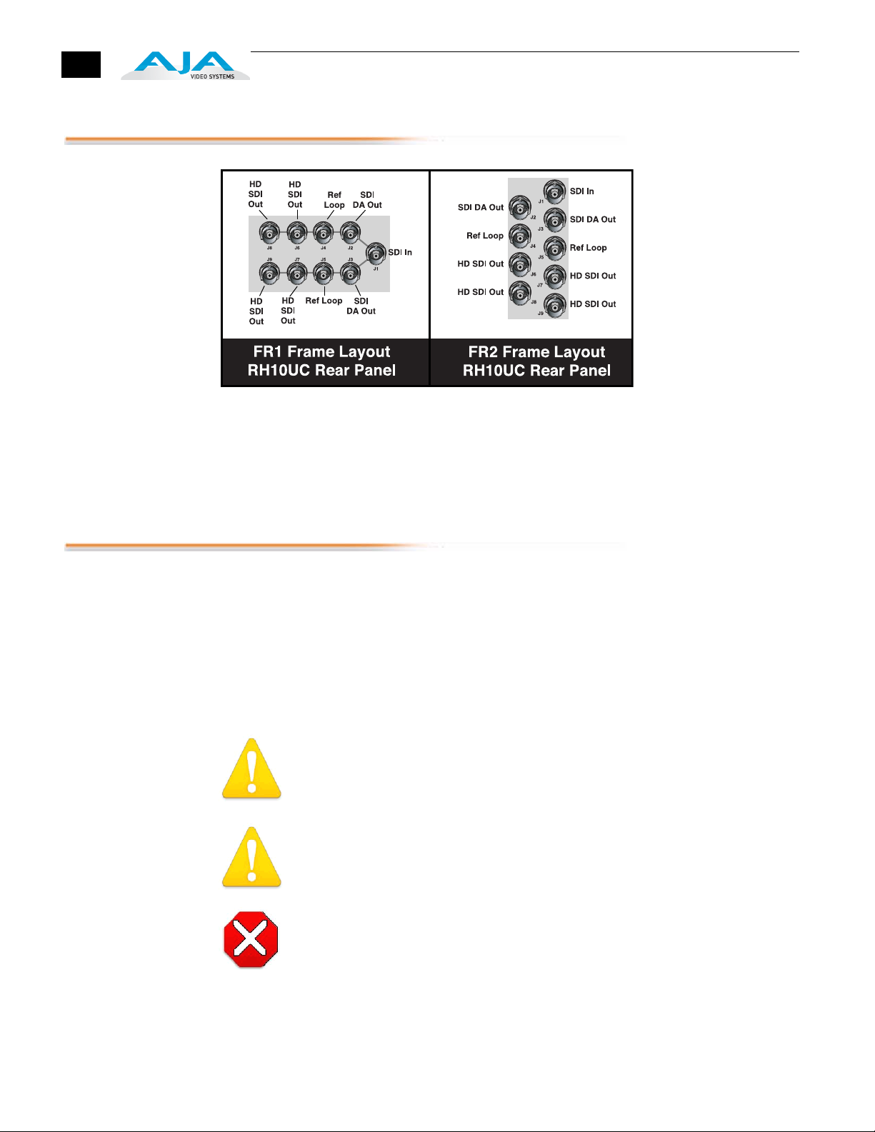
I/O Connections
1.
2.
3.
4.
5.
FR1 and FR2 BNC Connector Assignments, RH10UC Card Module
Installation
When the RH10UC module is installed in an AJA FR1 or FR2 frame, a corresponding group
of 9 BNCs on the rear panel then provide I/O for the module. The illustration above shows
the connector assignments for both the FR1 and FR2 when used with the RH10UC.
Typically, RH10UC installation consists of the following:
disconnect power from the frame (remove line cord)
remove the FR1/FR2 front panel
install RH10UC card module
replace the FR1/FR2 front panel
apply power to the frame by connecting a north american-style power cord from
the frame to mains power (90 to 260 VAC)
!
Warning!
Ensure Mains Power is disconnected before installing the FR1 or FR2 frame R-series
modules into the frame, or installing and removing options. If a Mains switch is not
provided, the power cord(s) of this equipment provide the means of disconnection.
The socket outlet must be installed near the equipment and must be easily accessible.
Warning!
FR2 Dual Power Cord Notice—please read this. To reduce the risk of electrical shock,
disconnect both power cords before servicing equipment.
Caution!
The FR1/FR2 front fan door is heavy and is not hinged. Remove with Caution.
Instructions for removing the frame front door for module installation is discussed in the
FR1/FR2 User Manual.
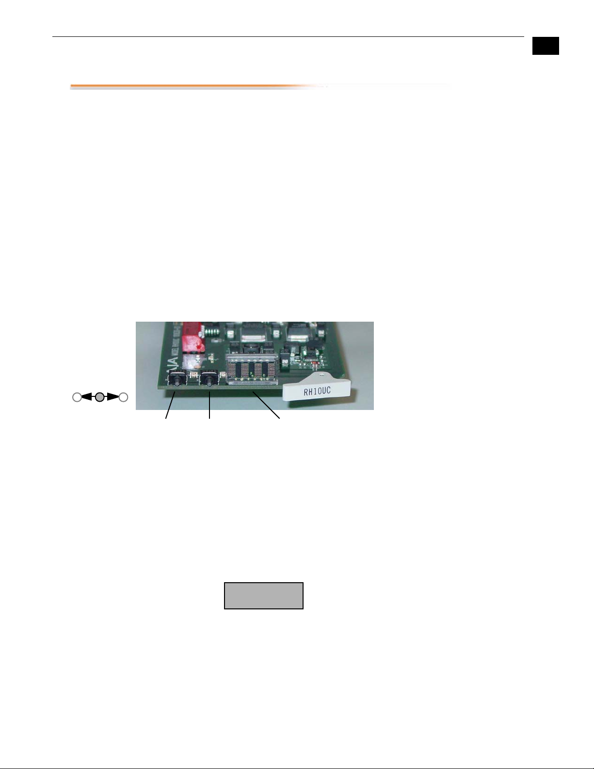
User Controls
AJA RH10UC SD to HD Upconverter User Manual
The user interface for the RH10UC consists of two toggle switches and a 4character alphanumeric display. See the photo “ RH10UC User Interface
Controls ” that follows for control location and function.
The Parameter Select (PS) switch selects a parameter for adjustment and
viewing on the display. Once a desired parameter is selected by moving the
PS switch, you then use the other switch—called Parameter Adjust (PA)—to
make a change to the parameter setting. Both switches are toggle switches
that can be pushed to the right or left, allowing you to move forward or
backward through available choices. After actuation, either switch will
return to a middle position.
1
If you move a switch and hold it in place (left or right), the RH10UC will
sense this and auto-increment or decrement.
By default, the 4-character display shows the current status of the
RH10UC—referred to as status mode. When you’re adjusting parameters or
settings, the display changes from status mode to adjust mode to show the
new value settings or parameters. After a period of inactivity the display
always reverts to status mode.
5
Switches
Toggle
Left and Right
PS Switch
Parameter Select
Normal
Operation Status
Mode
PA Switch
Parameter Adjust
RH10UC User Interface Controls
The RH10UC display by default will show you which inputs are present, any
detected error conditions, and the functional mode the board is in
(upconverting, downconverting, HD/SD framesync, etc.). After the board is
powered on, it enters status mode and stays there until a toggle switch is
selected and you enter adjust mode . After 5 seconds of inactivity in adjust
mode, it then returns to status mode.
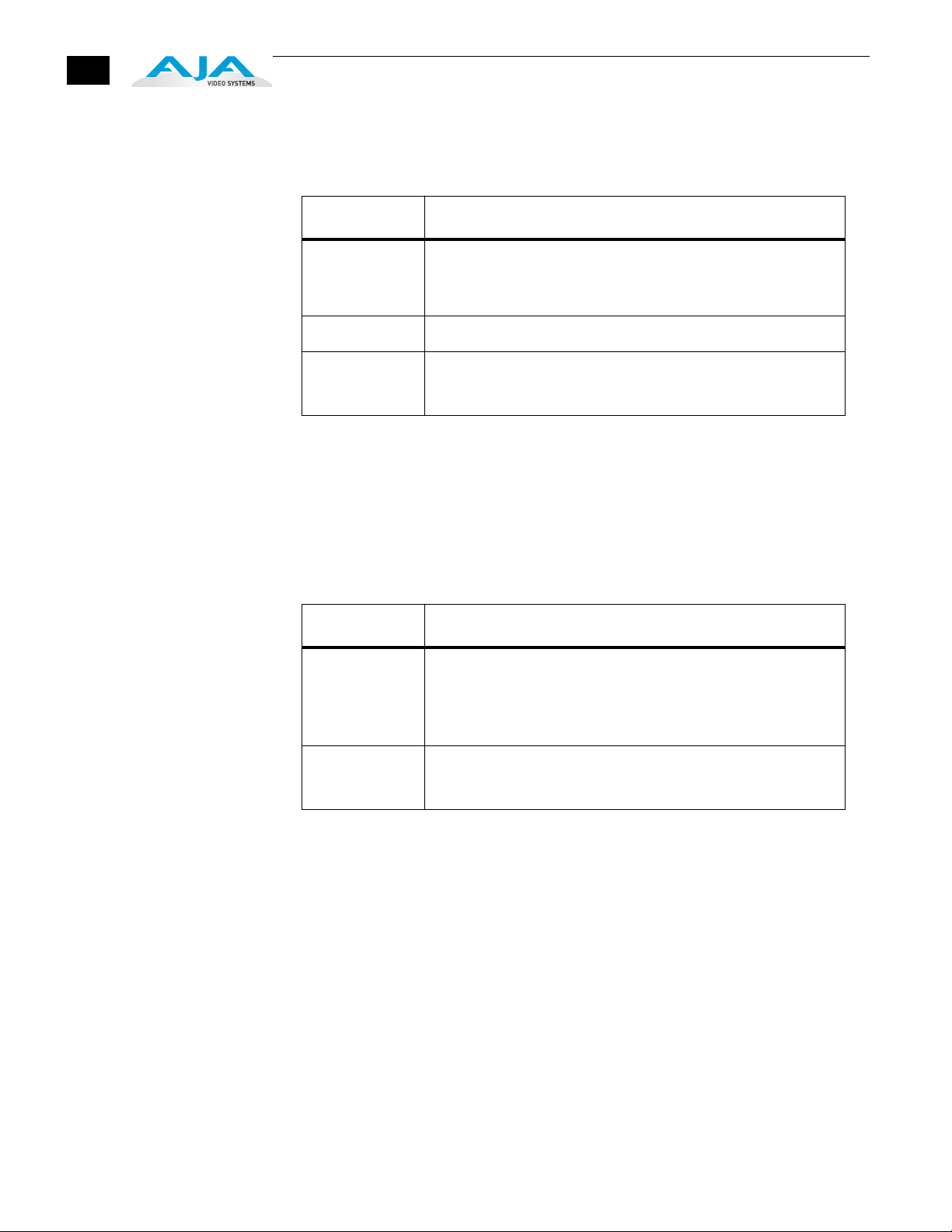
While in status mode, the 4-character display indicates the following:
4-Character
Display
8888
1 2 3 4
6
Table 2.
Character # Indicates
1 S—Standard Definition (SD) input signal present
E—Error on input signal
H—High definition signal present (HD Framesync mode only)
2 Blank—not used
Editing and
Viewing Board
Settings Adjust
Mode
3 or 4 Mode Mnemonic: these codes show what the board is doing
UP—up convert
HF—High Definition Framesync
Moving the PS switch in either direction causes the RH10UC to enter adjust
mode . When this happens, the display will change to indicate the
parameter being shown/edited.
Table 3.
Character # Indicates
1 Normally displays parameter number 0 through 9, and A to Z
(some numbers and letters are currently not used—only those
used will be discussed in this document).
If the parameter value (see below) exceeds 3-digits, this display
character will also be used so 4-digits of the value can be viewed.
1 to 4 A 1 to 4-character code that indicates a parameter value.
Usually the value will be shown in characters 2 through 4, except
when the value requires all 4 characters.
When a parameter is shown in adjust mode, the last selected parameter is
shown in character 1and the current parameter value is shown in
characters 2 through 4—if the value exceeds 3 digits, then all 4 characters
in the display are used to show the value. Parameter choices and their
definitions are listed in a table on the following page.
Selecting Parameters
Move the PS switch to the left to increment the parameter number or move
it to the right to decrement the parameter number. Characters 2 through 4
will change to reflect the settings of these parameters as they are
incremented/decremented.
Editing Parameters
When a parameter has been selected with the PS switch, use the PA switch
to then change the parameter value (as displayed by characters 2 through
4) to another value. Like the PS switch, you’ll move PA switch to the left or
 Loading...