


www.aja.com
Installation and Operation
Guide
Because it matters.
R20CE
10-bit Encoder
R-series Card Module
Published: 6/30/10

2
Trademarks
Notice
Contacting Support
®
AJA
are trademarks of AJA Video, Inc. HDMI, the HDMI logo and High-Definition Multimedia Interface are
trademarks or registered trademarks of HDMI Licensing LLC. DVI is a registered trademark of DDWG.
All other trademarks are the property of their respective holders.
Copyright © 2010 AJA Video, Inc. All rights reserved. All information in this manual is subject to
change without notice. No part of the document may be reproduced or transmitted in any form, or by
any means, electronic or mechanical, including photocopying or recording, without the express
written permission of AJA Inc.
To contact AJA Video for sales or support, use any of the following methods:
180 Litton Drive, Grass Valley, CA. 95945 USA
Telephone: 800.251.4224 or 530.274.2048
Fax: 530.274.9442
Web: http://www.aja.com
Support Email: support@aja.com
Sales Email: sales@aja.com
When calling for support, have all information at hand prior to calling.
®
, KONA
, Ki Pro®, and XENA
®
are registered trademarks of AJA Video, Inc. FiDO™, Io HD
™
and Io
™
Limited Warranty
AJA Video warrants that this product will be free from defects in materials and workmanship for a
period of five years from the date of purchase. If a product proves to be defective during this warranty
period, AJA Video, at its option, will either repair the defective product without charge for parts and
labor, or will provide a replacement in exchange for the defective product.
In order to obtain service under this warranty, you the Customer, must notify AJA Video of the defect
before the expiration of the warranty period and make suitable arrangements for the performance of
service. The Customer shall be responsible for packaging and shipping the defective product to a
designated service center nominated by AJA Video, with shipping charges prepaid. AJA Video shall
pay for the return of the product to the Customer if the shipment is to a location within the country in
which the AJA Video service center is located. Customer shall be responsible for paying all shipping
charges, insurance, duties, taxes, and any other charges for products returned to any other locations.
This warranty shall not apply to any defect, failure or damage caused by improper use or improper or
inadequate maintenance and care. AJA Video shall not be obligated to furnish service under this
warranty a) to repair damage resulting from attempts by personnel other than AJA Video
representatives to install, repair or service the product, b) to repair damage resulting from improper
use or connection to incompatible equipment, c) to repair any damage or malfunction caused by the
use of non-AJA Video parts or supplies, or d) to service a product that has been modified or integrated
with other products when the effect of such a modification or integration increases the time or
difficulty of servicing the product.
THIS WARRANTY IS GIVEN BY AJA VIDEO IN LIEU OF ANY OTHER WARRANTIES, EXPRESS OR IMPLIED.
AJA VIDEO AND ITS VENDORS DISCLAIM ANY IMPLIED WARRANTIES OF MERCHANTABILITY OR
FITNESS FOR A PARTICULAR PURPOSE. AJA VIDEO’S RESPONSIBILITY TO REPAIR OR REPLACE
DEFECTIVE PRODUCTS IS THE WHOLE AND EXCLUSIVE REMEDY PROVIDED TO THE CUSTOMER FOR
ANY INDIRECT, SPECIAL, INCIDENTAL OR CONSEQUENTIAL DAMAGES IRRESPECTIVE OF WHETHER AJA
VIDEO OR THE VENDOR HAS ADVANCE NOTICE OF THE POSSIBILITY OF SUCH DAMAGES.
Introduction
Features
AJA R20CE 10-bit Encoder User Manual
The AJA Video R20CE SDI to Analog Video Encoder produces high quality NTSC
or PAL 10-bit encoded video from SMPTE 259M SDI inputs. Three additional
analog outputs can be configured as duplicates of the composite output, or
used for component output. When configured for component video, the R20CE
can output Y/C (S-Video), YPbPr (SMPTE, EBU-N10), Betacam, or RGB.
The R20CE also serves as an SDI distribution amplifier, providing 2 re-clocked
outputs of the SDI input source. The R20CE is compatible with the AJA FR1 1RU
4 slot frame or the FR2 2RU 10 slot frame.
The component and composite outputs incorporate optimum chroma filtering
and independent pedestal configuration. The R20CE also features an exclusive
PLL jitter filter/memory to reduce the effects of SDI jitter on the output analog
video. This feature, along with the precision 4x oversampled D/A filters,
provides high quality analog outputs, with very low phase noise in the
composite outputs.
The optional AJA model FSG (Frame Sync/Genlock) Module allows genlock to
an external reference with full timing adjustment. Without the FSG Module, the
reference input provides color frame timing.
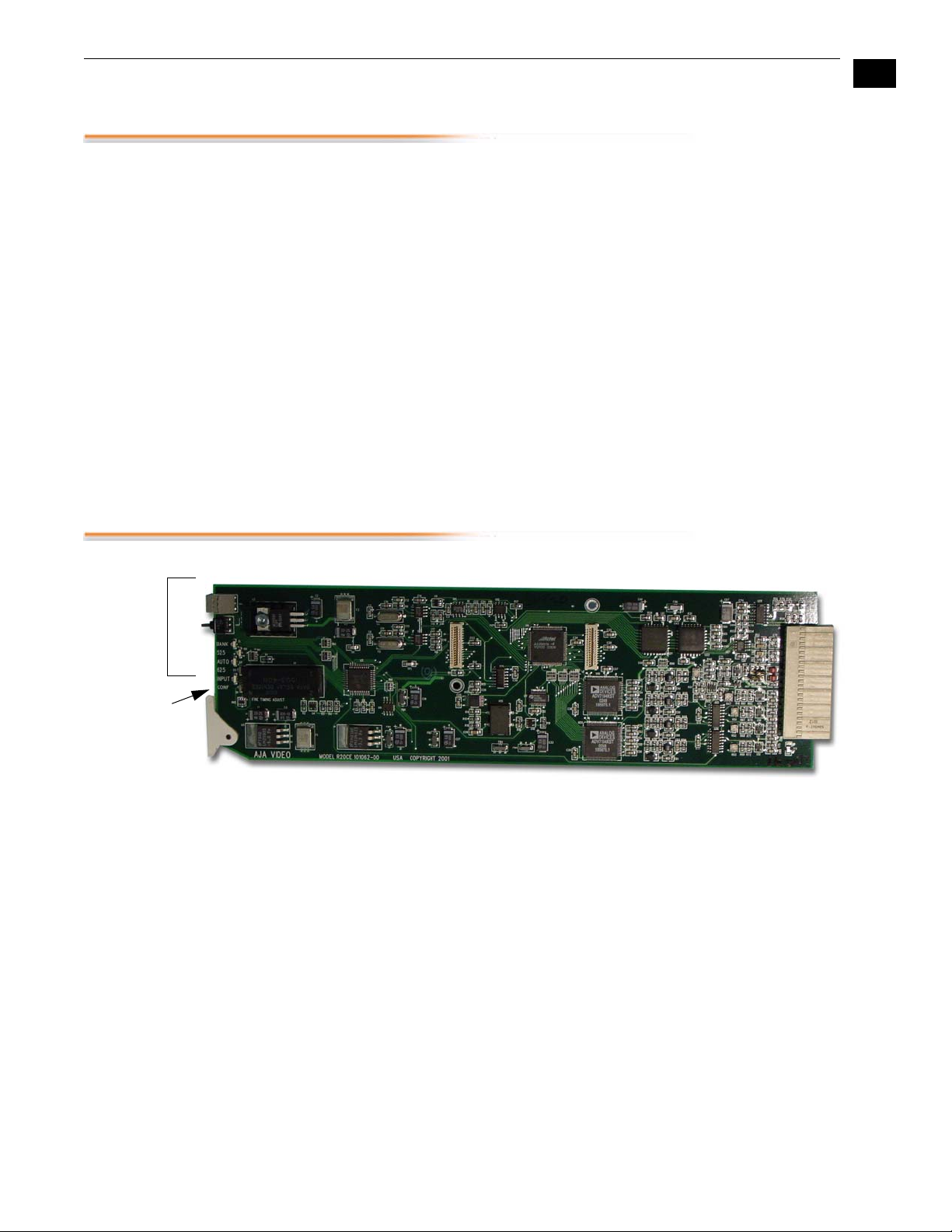
1
3
User
Controls
Timing
Adjustment
R20CE Card Module, Side View
•
High quality 10-bit encoding, 4 times oversampling
•
SDI Input, SMPTE 259M
•
Two SDI outputs (SMPTE 259M) (equalized and re-clocked copies of the
SDI input)
•
Four analog outputs (configurable as 4 composite, or 1 composite and R/
G/B, Y/Pb/Pr, or Y/C)
•
Y/Pb/Pr selectable for SMPTE/EBU levels or Betacam levels (Y, R-Y, B-Y)
•
Automatic NTSC/PAL selection
•
Configurable pedestal and narrow/wide H/V blanking
•
Frame Sync/Genlock option with reference input and full timing
adjustment~
•
Locks composite output Color Framing sequence to external reference
without Frame Sync/Genlock option,.
•
Plug compatible with several other manufacturers' video frames
•
Compatible with Leitch 6800 Series Frames

4
Block Diagram
Serial
Video
In
Cable
EQ
Clock
Filter
Encoder
27 MHz
Filter
COMPOSITE
ReClock
Serial/
Parallel
27 MHz
Frame
Mezzanine
(optional)
Bypass
27 MHz
FIFO
REF
LOOP
FRAME
REF
I/O Connections
PIC
Microcontroller
Filter
R20CE 10-bit Encoder, Block Diagram
CMPST
C/R/Pr
Out
CMPST
Y/B/Pb
Out
J8
J9
CMPST/
G/Y Out
J6
J7
CMPST
Out
Loop
J4
J5
Ref
Loop
Ref
Out 1
J2
J3
SDI
Out 2
SDI
SDI In
J1
CMPST -/G/Y Out
SDI Out 1
Ref Loop
CMPST/
C/R/Pr
Filter
Filter
Filter
Cable
Driver
SDI In
J1
J2
SDI Out 2
J3
J4
Ref Loop
J5
J6
CMPST Out
J7
CMPST/
J8
Y/B/Pb
J9
COMP/_/G/Y
COMP/Y/B/B-Y
COMP/C/R/R-Y
1
Serial
Out
2
FR1 Frame Layout
R20CE Rear Panel
FR2 Frame Layout
R20CE Rear Panel
FR1 and FR2 BNC Connector Assignments, R20CE Card Module
When the R20CE module is installed in an AJA FR1 or FR2 frame, a corresponding
group of 9 BNCs on the rear panel then provide I/O for the module. The
illustration above shows the connector assignments for both the FR1 and FR2
when used with the R20CE.
Note:
See the topic “ External Reference Information ” later in this manual for
information on use of the Ref Loop BNCs versus the FR1/FR2 frame reference BNC
when connecting an external reference video signal.

User Controls
Rotary
Switch
Bank
Switch
LEDs
AJA R20CE 10-bit Encoder User Manual
The user interface for the R20CE includes a 16 position hex
rotary switch, a momentary action up/down toggle switch,
and 6 LEDs. Use the rotary switch to select a function and
then adjust the function using the toggle switch. The BANK
Led allows two banks of functions to be accessed, The LEDs
are numbered 1-6 from top to bottom. The LEDs are labeled
as follows:
LED FUNCTION
1 BANK (OFF=Bank O
ON=Bank 1)
2 525
3 AUTO (auto 525/625 select)
4 625
1
5
Control Functions
5 VID (video detected at input)
6 CONFIRM (for signaling memory
load, errors, etc.)
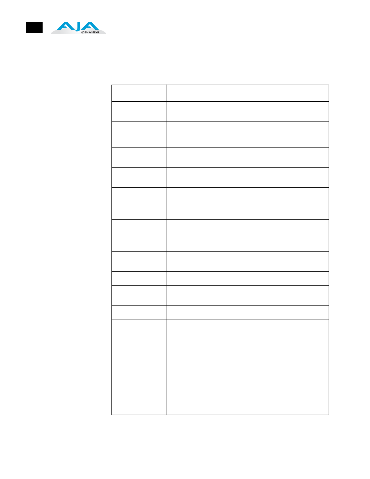
The following tables describe the functions controlled by the rotary switch and toggle
switch user interface. To access a particular function, set the hex rotary switch to the
appropriate function, and then adjust the function by flipping the toggle switch. For
ON/OFF-type functions, such as Setup/NoSetup selection, moving the toggle switch to
the UP/LEFT position sets the function and moving the switch DOWN/RIGHT clears the
function. Using the toggle with multi-value functions, such as INPUT MODE, rotates
through all the possible choices for the function. To control variables, such as
framesync delay, the value of the function will be incremented or decremented each
time the switch is momentarily moved either up, or down respectively. Holding the
switch in either position will cause the function to automatically begin incrementing or
decrementing—after a two second pause. On functions having more than two
selections, using the toggle switch cycles through the available selections.
6
Bank 0 Functions
FUNCTION DESCRIPTION DETAILS
0 BANK SEL ToggleUP/LEFT to select BANK 1
1 |NPUT MODE 0 = Auto Select
2 VBLANK UP/LEFT = Narrow
3 SETUP UP/LEFT = No Pedestal
4 OUTPUT MODE 0 = Composite on all
5 COMPONENT
LEVELS
6 INPUT SOURCE Toggle DOWN to pass video.
7 <reserved>
Toggle DOWN/RIGHT to select BANK 0
1 = 525
2 = 625
DOWN/RIG HT = Wide
DOWN/RIGHT=AddPedestal
1 = Y,Pb,Pr
2 = RGB
3 = Y/C
UP/LEFT = BETACAM 525 (Y, R-Y,B-Y)
DOWN/RIGI[T = SMPTE EBU N-10/
BETACAM 625 (Y,Pb,Pr)
(When OUTPUT MODE = Y,Pb,Pr)
Toggle UP for Bars (Internal test signal)
8 CLEAR USER
SETUP
9 RESET Toggle either way to reset board
A <reserved>
B <reserved>
C <reserved>
D <reserved>
E STORE/RECALL Toggle UP to store register
F RESTORE
DEFAULTS
Toggle either way to clear User EEPROM
and reset board
Toggle DOWN to recall register
Toggle either way to restore default settings
 Loading...