


www.aja.com
Installation and Operation
Guide
Because it matters.
R20AD
10-bit Universal Decoder
R-series Card Module
Published: 6/30/10

2
Trademarks
Notice
Contacting Support
®
AJA
are trademarks of AJA Video, Inc. HDMI, the HDMI logo and High-Definition Multimedia Interface are
trademarks or registered trademarks of HDMI Licensing LLC. DVI is a registered trademark of DDWG.
All other trademarks are the property of their respective holders.
Copyright © 2010 AJA Video, Inc. All rights reserved. All information in this manual is subject to
change without notice. No part of the document may be reproduced or transmitted in any form, or by
any means, electronic or mechanical, including photocopying or recording, without the express
written permission of AJA Inc.
To contact AJA Video for sales or support, use any of the following methods:
180 Litton Drive, Grass Valley, CA. 95945 USA
Telephone: 800.251.4224 or 530.274.2048
Fax: 530.274.9442
Web: http://www.aja.com
Support Email: support@aja.com
Sales Email: sales@aja.com
When calling for support, have all information at hand prior to calling.
®
, KONA
, Ki Pro®, and XENA
®
are registered trademarks of AJA Video, Inc. FiDO™, Io HD
™
and Io
™
Limited Warranty
AJA Video warrants that this product will be free from defects in materials and workmanship for a
period of five years from the date of purchase. If a product proves to be defective during this warranty
period, AJA Video, at its option, will either repair the defective product without charge for parts and
labor, or will provide a replacement in exchange for the defective product.
In order to obtain service under this warranty, you the Customer, must notify AJA Video of the defect
before the expiration of the warranty period and make suitable arrangements for the performance of
service. The Customer shall be responsible for packaging and shipping the defective product to a
designated service center nominated by AJA Video, with shipping charges prepaid. AJA Video shall
pay for the return of the product to the Customer if the shipment is to a location within the country in
which the AJA Video service center is located. Customer shall be responsible for paying all shipping
charges, insurance, duties, taxes, and any other charges for products returned to any other locations.
This warranty shall not apply to any defect, failure or damage caused by improper use or improper or
inadequate maintenance and care. AJA Video shall not be obligated to furnish service under this
warranty a) to repair damage resulting from attempts by personnel other than AJA Video
representatives to install, repair or service the product, b) to repair damage resulting from improper
use or connection to incompatible equipment, c) to repair any damage or malfunction caused by the
use of non-AJA Video parts or supplies, or d) to service a product that has been modified or integrated
with other products when the effect of such a modification or integration increases the time or
difficulty of servicing the product.
THIS WARRANTY IS GIVEN BY AJA VIDEO IN LIEU OF ANY OTHER WARRANTIES, EXPRESS OR IMPLIED.
AJA VIDEO AND ITS VENDORS DISCLAIM ANY IMPLIED WARRANTIES OF MERCHANTABILITY OR
FITNESS FOR A PARTICULAR PURPOSE. AJA VIDEO’S RESPONSIBILITY TO REPAIR OR REPLACE
DEFECTIVE PRODUCTS IS THE WHOLE AND EXCLUSIVE REMEDY PROVIDED TO THE CUSTOMER FOR
ANY INDIRECT, SPECIAL, INCIDENTAL OR CONSEQUENTIAL DAMAGES IRRESPECTIVE OF WHETHER AJA
VIDEO OR THE VENDOR HAS ADVANCE NOTICE OF THE POSSIBILITY OF SUCH DAMAGES.
Introduction
Features
User
Controls
AJA R20AD 10-bit Universal Decoder User Manual
The AJA R20AD provides excellent-quality 10-bit conversion to SDI from
component or NTSC/PAL sources. The R20AD accepts YPbPr (SMPTE, EBU-N10),
Betacam, or RGB component inputs and NTSC/PAL or Y/C (S-Video) composite
inputs. Featured in the R20AD is a 4 Line Adaptive Comb Filter for high quality
decoding of composite sources. The comb filter can be switched to 2-line, or
notch modes for minimum delay requirements. The R20AD also accommodates
an optional FSG card (Frame Sync) for synchronizing the output video relative
to an external reference. NTSC/PAL configuration is automatic. Video format,
AGC, H/V blanking, and pedestal are all user configurable.
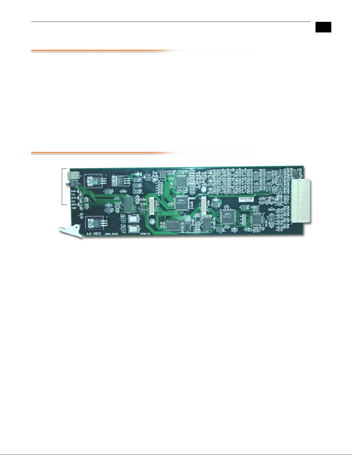
The R20AD is a 10.3” X 3.1” card, designed to plug into The AJA Video FR1-1 RU
frame and the AJA Video FR2-2 RU frame.
1
3
R20AD Card Module, Side View
•
Excellent quality 10-bit adaptive comb filter decoding
•
Component (YPbPr, Betacam, RGB), PAL and NTSC Composite and Y/C (S
Video) inputs
•
Four serial outputs (SMPTE 259M)
•
Automatic NTSC/PAL selection
•
Configurable pedestal and Comb filter
•
2X Oversampling
•
Frame Sync/Genlock option with external reference inputs and full timing
adjustment
•
Plug compatible with several other manufacturers’ video frames
4
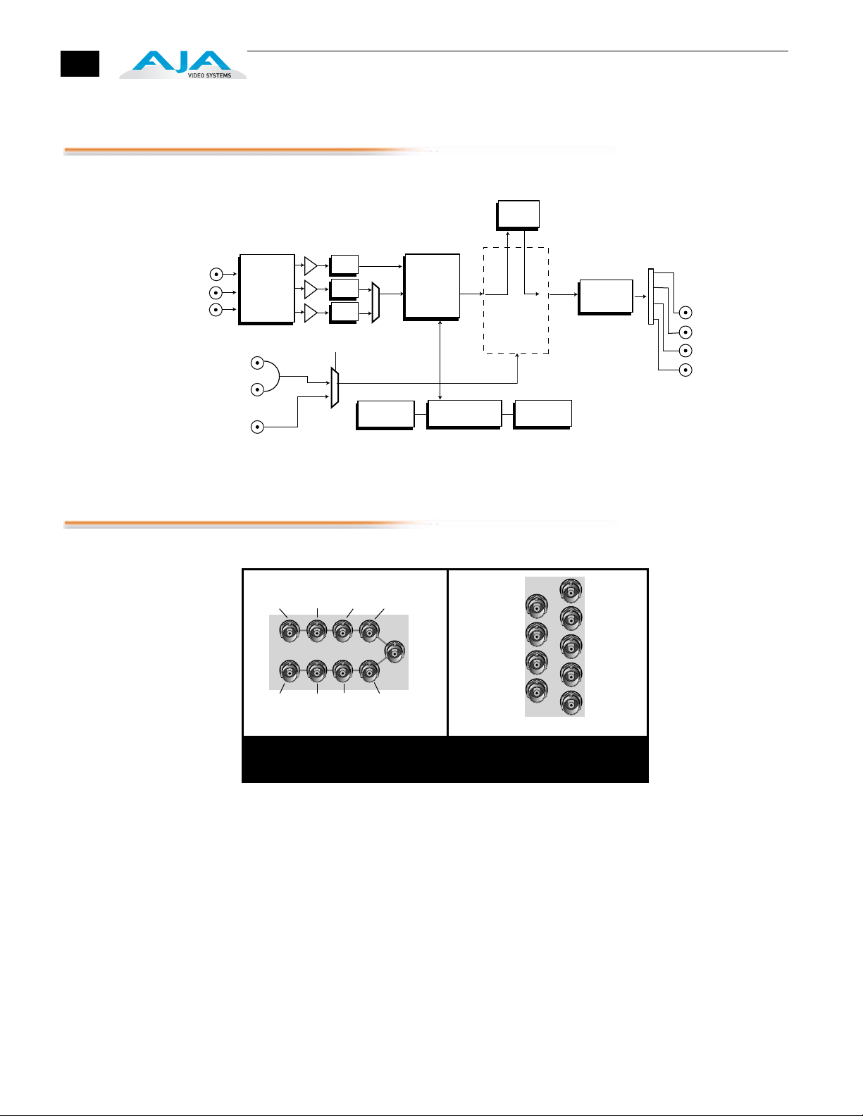
Block Diagram
Bypass
Composite/Y/G
C/Pr/R
Pb/B
I/O Connections
Filter
Filter
Filter
Select
Switches &
LEDs
A/D
Converter &
Decoder
Framesync
Microprocessor EEPROM
REF
LOOP
FRAME
REF
Color Space
Converter
&
Input Select
R20AD 10-bit Universal Decoder, Block Diagram
SDI
SDI
SDI
Ref
Pb/B/C
Loop
J2
J4
J6
J7
J5
Ref
Loop
J3
Pr/R
Cmpst
/Y/G
J1
Pb/B/C
Ref Loop
SDI Out 1
SDI Out 3
Out 3
SDI
Out 4
Out 1
J8
J9
Out 2
Genlock
Module
Serialize
Serial Out 1
Serial Out 2
Serial Out 3
Serial Out 4
Cmpst
/Y/G
J1
J2
Pr/R
J3
J4
Ref Loop
J5
J6
SDI Out 2
J7
J8
SDI Out 4
J9
FR1 Frame Layout
R20AD Rear Panel
FR2 Frame Layout
R20AD Rear Panel
FR1 and FR2 BNC Connector Assignments, R20AD Card Module
When the R20AD module is installed in an AJA FR1 or FR2 frame, a corresponding
group of 9 BNCs on the rear panel then provide I/O for the module. The
illustration above shows the connector assignments for both the FR1 and FR2
when used with the R20AD.
Note:
See the topic “ External Reference Information ” later in this manual for
information on use of the Ref Loop BNCs versus the FR1/FR2 frame reference BNC
when connecting an external reference video signal.
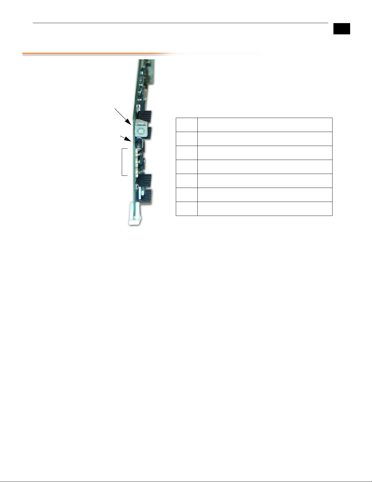
User Controls
Rotary
Switch
Bank
Switch
LEDs
AJA R20AD 10-bit Universal Decoder User Manual
The user interface for the R20AD consists of a 16-position hex
rotary switch, a momentary action up/down toggle switch,
and 6 LEDs that indicate status. The rotary switch selects a
function or setting to be controlled by the toggle switch. The
BANK LED (LED 1) shows which of two banks of functions are
to be accessed. The LEDs are numbered 1-6 from top to
bottom or left to right. The LEDs are labeled as follows:
LED FUNCTION
1
2 525
3 AUTO (auto 525/625 select)
4 625
5 VID (video detected at input)
BANK (LED OFF = Bank 0, ON = Bank 1)
1
5
Control Functions
6 CONFIRM (for signaling memory load, errors, etc.)
The following tables describe the functions controlled by the user interface. To access a
particular function, set the hex rotary switch to the appropriate function, and then use
the toggle switch to adjust the selected function. For on/off type functions, such as
Setup/NoSetup selection, move the switch to the UP/LEFT position to set the function
or move the switch DOWN/RIGHT to clear the function. Multi-value functions such as
INPUT MODE will rotate through the possible choices for the function. To control
variables, such as framesync delay, the value of the function will be incremented or
decremented each time the switch is momentarily moved either up, or down
respectively. Holding the switch in either position causes the function to automatically
increment or decrement, after a two second pause. With functions having more than
two selections, the toggle switch cycles through the available selections.
Note:
for input format selection, select either composite or component (function 4)
before selecting between types of composite or component (function 5).

Bank 0 Functions
6
FUNCTION
0 BANK SEL Toggle UP/LEFT to select BANK 1
1 INPUT MODE Toggle to cycle through these selections:
2
3 SETUP/PEDESTAL
DESCRIPTION DETAILS
Toggle DOWN/RIGHT to select BANK 0 (Default)
Auto Select (Default). Currently, AUTO SELECT is the
only selection.
VERTICAL BLANK UP/LEFT = Blank Vertical Interval
REMOVEL
DOWN/RIGHT = Pass Vertical Interval (Default)
Currently, Pass Vertical Interval (narrow blanking) is the
only selection
UP/LEFT = No Pedestal on Input Video
DOWN/RIGHT = Input Pedestal Present (Default)
Functions only IN NTSC
4
5 RGB/YPbPr/YC UP/LEFT = YPbPr if Component selected above or YC
6 COMPONENT LEVELS UP/LEFT = SMPTE/EBU-N10 Levels (Default)
7 AGC UP/LEFT = Automatic Gain Control ON
COMPONENT/
COMPOSITE
UP/LEFT = Component Input (Default)
DOWN/RIGHT = Composite Input
if Composite selected above
DOWN/RIGHT = RGB if Component selected above or
Composite if Composite selected above
DOWN/RIGHT = Betacam 525/60 Levels
DOWN/RIGHT = Automatic Gain Control OFF (Default)
8 CLEAR EEPROM and
RESET
9 RESET Toggle either way to reset
A COMB FILTER UP/LEFT = Comb OFF
B COMB TYPE UP/LEFT = Adaptive 3 line Comb
C EDH UP/LEFT = EDH OFF
D TEST PATTERN UP/LEFT = Pass Input (Normal Operation) (Default)
E STORE/RECALL
USER SETUP
F RESTORE DEFAULTS Toggle UP/DOWN to Restore Default Settings
Toggle either way to clear EEprom contents, then
resets
DOWN/RIGHT = Comb ON (Default)
DOWN/RIGHT = Adaptive 4 line Comb (Default)
DOWN/RIGHT = EDH ON (Default)
DOWN/RIGHT = Output Internal Test Pattern
Toggle UP/LEFT to Store Register
Toggle DOWN/RIGHT to Recall Register
 Loading...