

Page 1
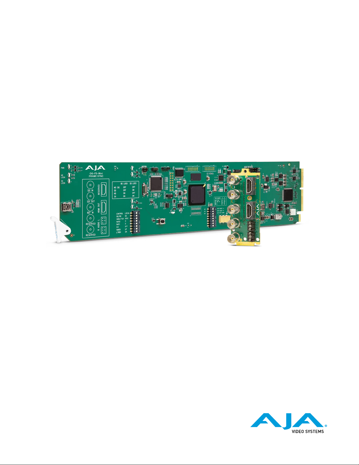
OG-FS-Mini
Frame Synchronizer
Installation and Operation Guide
Version 1.5.1
Published March 1, 2021
Page 2
Notices
Trademarks
Copyright
AJA® and Because it matters.® are registered trademarks of AJA Video Systems, Inc.
for use with most AJA products. AJA™ is a trademark of AJA Video Systems, Inc. for
use with recorder, router, software and camera products. Because it matters.™ is a
trademark of AJA Video Systems, Inc. for use with camera products.
Corvid Ultra®, lo®, Ki Pro®, KONA®, KUMO®, ROI® and T-Tap® are registered trademarks of
AJA Video Systems, Inc.
AJA Control Room™, KiStor™, Science of the Beautiful™, TruScale™, V2Analog™ and
V2Digital™ are trademarks of AJA Video Systems, Inc.
All other trademarks are the property of their respective owners.
Copyright © 2021 AJA Video Systems, Inc. All rights reserved. All information in
this manual is subject to change without notice. No part of the document may be
reproduced or transmitted in any form, or by any means, electronic or mechanical,
including photocopying or recording, without the express written permission of AJA
Video Systems, Inc.
Contacting AJA Support
When calling for support, have all information at hand prior to calling. To contact AJA
for sales or support, use any of the following methods:
Telephone +1.530.271.3190
FAX +1.530.271.3140
Web
Support Email
Sales Email
https://www.aja.com
OG-FS-Mini Frame Synchronizer v1.5.1 2 www.aja.com
Page 3

Contents
Notices . . . . . . . . . . . . . . . . . . . . . . . . . . . . . . . . . . . . . .2
Trademarks . . . . . . . . . . . . . . . . . . . . . . . . . . . . . . . . . . . . . . . . . . . 2
Copyright . . . . . . . . . . . . . . . . . . . . . . . . . . . . . . . . . . . . . . . . . . . . 2
Contacting AJA Support . . . . . . . . . . . . . . . . . . . . . . . . . . . . . . . . . . . 2
Chapter 1 – Introduction . . . . . . . . . . . . . . . . . . . . . . . . . . . 4
Overview. . . . . . . . . . . . . . . . . . . . . . . . . . . . . . . . . . . . . . . . . . . . . 4
Features. . . . . . . . . . . . . . . . . . . . . . . . . . . . . . . . . . . . . . . . . . . . 4
Video Formats. . . . . . . . . . . . . . . . . . . . . . . . . . . . . . . . . . . . . . . . 5
Block Diagram . . . . . . . . . . . . . . . . . . . . . . . . . . . . . . . . . . . . . . . . . 5
openGear and AJA. . . . . . . . . . . . . . . . . . . . . . . . . . . . . . . . . . . . . . . 5
I/O Connections . . . . . . . . . . . . . . . . . . . . . . . . . . . . . . . . . . . . . . . . 6
Signal Indicators on the OG-FS-Mini Card . . . . . . . . . . . . . . . . . . . . . . 6
Signal Indicators in the DashBoard Control System . . . . . . . . . . . . . . . . 6
Frame Sync Mode Example . . . . . . . . . . . . . . . . . . . . . . . . . . . . . . . . . 8
Setup . . . . . . . . . . . . . . . . . . . . . . . . . . . . . . . . . . . . . . . . . . . . . 8
Procedure. . . . . . . . . . . . . . . . . . . . . . . . . . . . . . . . . . . . . . . . . . .8
Conversion Mode Discussion and Examples . . . . . . . . . . . . . . . . . . . . . . 9
Upconvert Mode . . . . . . . . . . . . . . . . . . . . . . . . . . . . . . . . . . . . . . 9
Downconvert Mode . . . . . . . . . . . . . . . . . . . . . . . . . . . . . . . . . . . 10
SD Aspect Ratio Convert . . . . . . . . . . . . . . . . . . . . . . . . . . . . . . . . 11
User Controls . . . . . . . . . . . . . . . . . . . . . . . . . . . . . . . . . . . . . . . . . 12
DIP Switches . . . . . . . . . . . . . . . . . . . . . . . . . . . . . . . . . . . . . . . . 13
DashBoard Control System. . . . . . . . . . . . . . . . . . . . . . . . . . . . . . . 13
Installation. . . . . . . . . . . . . . . . . . . . . . . . . . . . . . . . . . . . . . . . . . . 13
Summary . . . . . . . . . . . . . . . . . . . . . . . . . . . . . . . . . . . . . . . . . . 13
Unpacking . . . . . . . . . . . . . . . . . . . . . . . . . . . . . . . . . . . . . . . . . 13
Rear OG-FS-Mini Card Installation . . . . . . . . . . . . . . . . . . . . . . . . . . 14
Front OG-FS-Mini Card Installation. . . . . . . . . . . . . . . . . . . . . . . . . . 15
Cabling . . . . . . . . . . . . . . . . . . . . . . . . . . . . . . . . . . . . . . . . . . . 16
Chapter 2 – Operation. . . . . . . . . . . . . . . . . . . . . . . . . . . .17
Default Operational Settings . . . . . . . . . . . . . . . . . . . . . . . . . . . . . . . 17
Using DIP Switches to Control the OG-FS-Mini . . . . . . . . . . . . . . . . . . . . 17
General Conguration DIP Switches . . . . . . . . . . . . . . . . . . . . . . . . . 17
Reference Selection DIP Switches . . . . . . . . . . . . . . . . . . . . . . . . . . 19
Using the DashBoard Control System. . . . . . . . . . . . . . . . . . . . . . . . . . 19
Requirements . . . . . . . . . . . . . . . . . . . . . . . . . . . . . . . . . . . . . . . 19
Control Interface Basic Components . . . . . . . . . . . . . . . . . . . . . . . . 19
Card Tab Screen. . . . . . . . . . . . . . . . . . . . . . . . . . . . . . . . . . . . . . 21
Status Tab Screen . . . . . . . . . . . . . . . . . . . . . . . . . . . . . . . . . . . . . 21
Video Tab Screen . . . . . . . . . . . . . . . . . . . . . . . . . . . . . . . . . . . . . 22
HDMI Tab Screen . . . . . . . . . . . . . . . . . . . . . . . . . . . . . . . . . . . . . 24
Audio Tab Screen . . . . . . . . . . . . . . . . . . . . . . . . . . . . . . . . . . . . . 26
Setup Tab Screen . . . . . . . . . . . . . . . . . . . . . . . . . . . . . . . . . . . . . 27
Upload Screen. . . . . . . . . . . . . . . . . . . . . . . . . . . . . . . . . . . . . . . 28
Rebooting . . . . . . . . . . . . . . . . . . . . . . . . . . . . . . . . . . . . . . . . . 30
Appendix A – Specications . . . . . . . . . . . . . . . . . . . . . . . . 31
OG-FS-Mini Tech Specs. . . . . . . . . . . . . . . . . . . . . . . . . . . . . . . . . . . 31
Appendix B – Safety and Compliance . . . . . . . . . . . . . . . . . . 35
Warranty and Liability Information . . . . . . . . . . . . . . . . . . . .44
Limited Warranty on Hardware. . . . . . . . . . . . . . . . . . . . . . . . . . . . . . 44
Limitation of Liability . . . . . . . . . . . . . . . . . . . . . . . . . . . . . . . . . . . . 44
Governing Law and Language; Your Rights . . . . . . . . . . . . . . . . . . . . . . 44
Index. . . . . . . . . . . . . . . . . . . . . . . . . . . . . . . . . . . . . . .46
OG-FS-Mini Frame Synchronizer v1.5.1 3 www.aja.com
Page 4
Chapter 1 – Introduction
Overview
Features
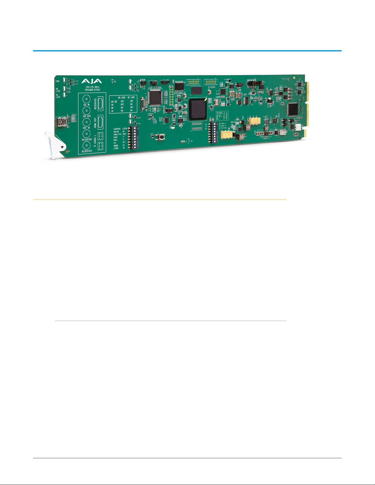
OG-FS-Mini is an openGear broadcast quality utility frame sync that packs the
production-proven functionality and all of the reliability of AJA’s leading FS frame
sync technology into an OG card supporting frame synchronization of untimed
3G-SDI, HD, and SD video signals at an affordable price.
OG-FS-Mini allows users to synchronize and convert a wide range of video
formats to their house standard with a 3G-SDI input and output, HDMI output,
and two 3-pin terminal block connectors for balanced analog audio outputs. The
OG-FS-Mini also provides high quality up, down, cross-conversion.
Designed for use in high-density openGear’s 2RU frames and AJA’s OG-X-FR 2RU
frame, DashBoard Software support on Windows®, macOS® and Linux offers
remote control and monitoring of the openGear architecture and provides
convenient and industry-standard configuration, monitoring and control options
over a PC or local network.
• openGear compatible card
• Utility frame sync function times input signals to an external reference
• Supports bi-level and tri-level references
• High quality 10-bit video processing
• Low latency processing, nominal video delay of 1 frame
• Freeze (on input signal loss) to black, last good frame, or timed mute delay
• Supports 1080p, 1080i, 720p, 625i, 525i, and SDI input signals
• Simultaneous SDI and HDMI outputs
• 16-channel embedded SDI audio I/O
• 8-channel HDMI output audio
• 2x 3-Pin terminal block connectors for analog audio output (included)
• Utility frame rate conversion
• Supports 3:2 pulldown
• Up, down, cross conversion between 3G, HD and SD video formats
• AFD input detection, down-convert control
OG-FS-Mini Frame Synchronizer v1.5.1 4 www.aja.com
Page 5
• Remote conguration through DashBoard Control System for an openGear
with Embedded
Re
Frame
• Rear I/O card included
• Compatible with OG-X-FR, OG3 and DFR-8321 openGear frames
• Five year warranty
NOTE: OG-FS-Mini converts 3G-SDI Level A formats only. It does not input or output
Video Formats
The OG-FS-Mini provides utility frame rate conversion within the same frame
rate family as the input frame rate. If a reference is provided, it must be in the
same frame rate hierarchy as the input video (e.g., 23.98/29.97/59.94, 25/25, or
24/30/60).
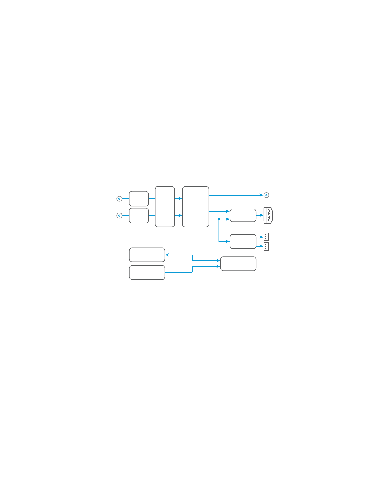
Block Diagram
Figure 1. OG-FS-Mini, Simplified Block Diagram
3G-SDI Level B.
SDI Input
ference Input Genlock
openGear and AJA
openGear is an open-architecture, modular frame system designed by Ross
Video and supported by a diverse range of terminal equipment manufacturers,
including AJA. Ross Video manufactures the frames, power supplies and network
cards for openGear. AJA is a reseller of the openGear frames.
AJA Video is a leading manufacturer of video interface technologies, converters,
digital video recording solutions and professional cameras, bringing highquality, cost-effective products to the professional, broadcast and postproduction markets. AJA products, including openGear cards, are designed and
manufactured at our facilities in Grass Valley, California.
SDI
Receiver
DashBoard
DIP Switch
User Interface
Frame
Sync
Up,
Down,
and
Cross
Converter
Video with Embedded Audio
Video
Audio
HDMI
Transmitter
Audio
D/A
Control
SDI Output
HDMI Output
Audio
2-Channel
Analog Audio
Output
OG-FS-Mini Frame Synchronizer v1.5.1 5 www.aja.com
Page 6
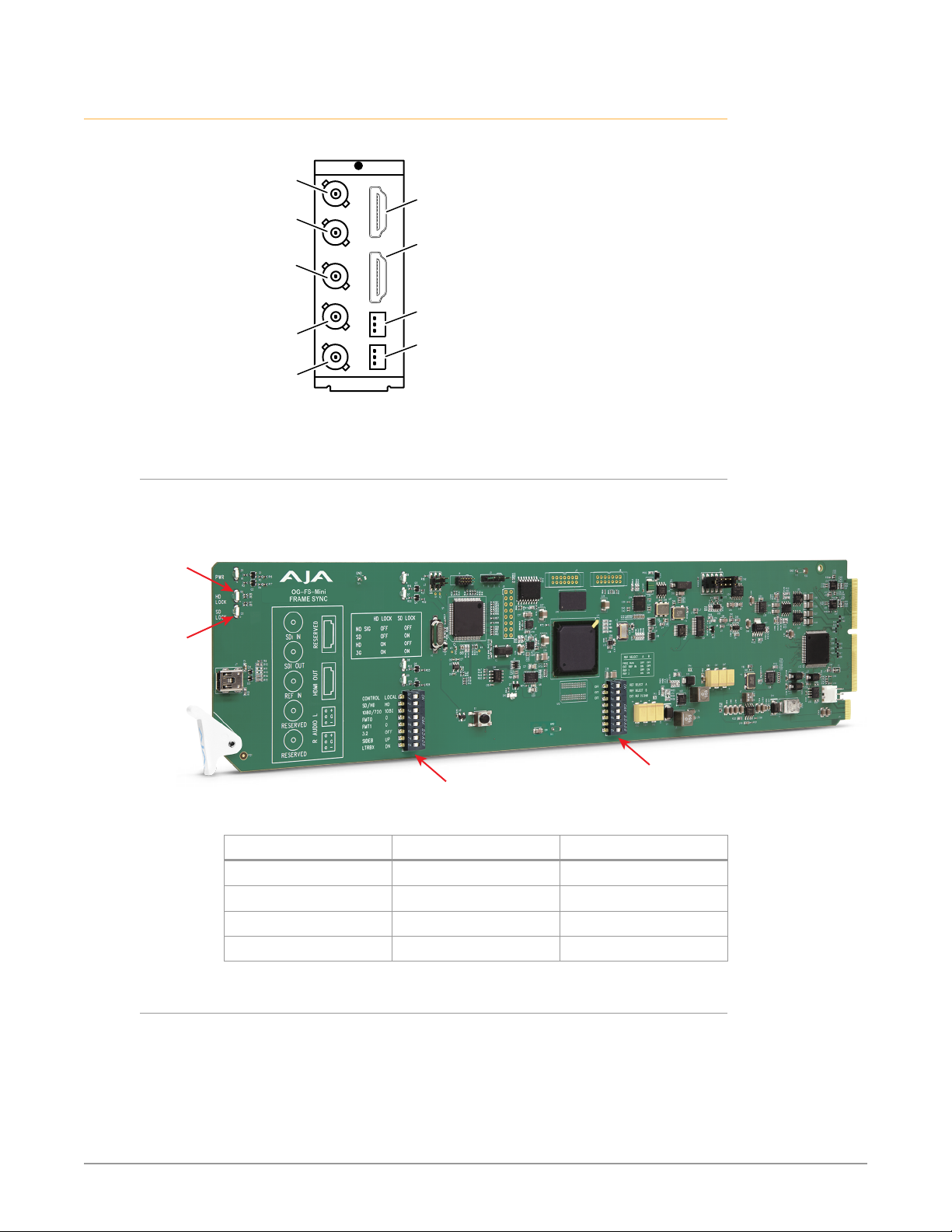
I/O Connections
HD Lock LED
Figure 2. I/O Connections for the OG-FS-Mini
SDI Input
BNC (J1)
SDI Output
BNC (J2)
Reference
Input
BNC (J3)
(inactive)
(inactive)
Each 3-pin analog audio connector carries one channel of analog audio output.
Signal Indicators on the OG-FS-Mini Card
Located at the upper front area of the OG-FS-Mini card, the HD Lock and SD Lock
LEDs work in combination to indicate the type of signal detected.
(inactive)
HDMI Output
Analog Audio
Output L
Analog Audio
Output R
Figure 3. Indicator LEDs and DIP Switch Locations on Card
SD Lock LED
General
DIP Switch
Signal Detected HD Lock Light SD Lock Light
No Signal O O
SD Signal O On
HD Signal On O
3G Signal On On
Signal Indicators in the DashBoard Control System
Reference
DIP Switch
When the signal is either not present or is not locked, the DashBoard Control
System shows both a yellow Card State alarm and a yellow Signal State alarm
under the Status tab. Additionally, the SDI Signal Type is shown as "No Signal."
OG-FS-Mini Frame Synchronizer v1.5.1 6 www.aja.com
Page 7
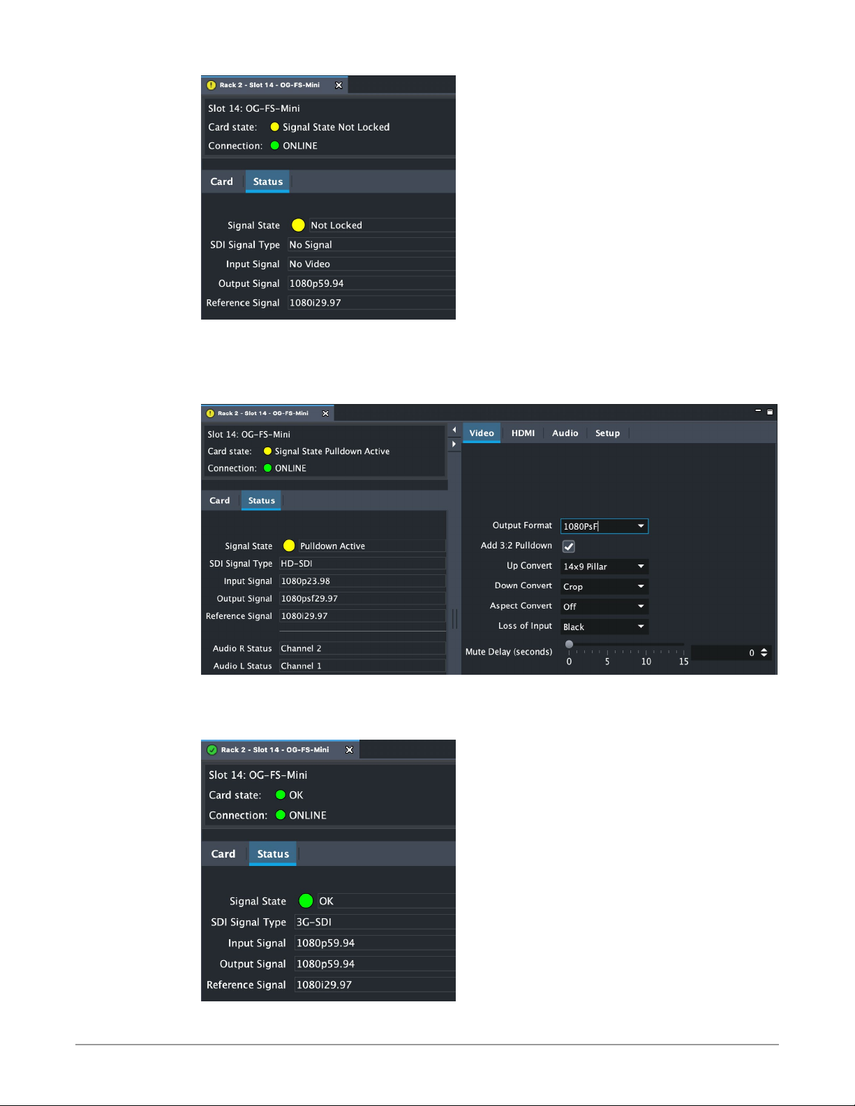
When the Add 3:2 Pulldown control has been turned on (indicated by a check
mark), and the output frame rates are not the same as the input rates of 23.98 and
24.00, the DashBoard Control System displays a yellow Card State and a yellow
Signal State with a "Pulldown Active" alarm warning.
When a signal is present and locked, the DashBoard Control System shows a
green Card State and a green Signal State under the Status tab. The SDI Signal
Type is also indicated (for example, "3G-SDI").
OG-FS-Mini Frame Synchronizer v1.5.1 7 www.aja.com
Page 8

NOTE: Alarms always show the highest priority alarm first. When that alarm condition is
resolved, the next alarm/warning condition will display, etc.
Frame Sync Mode Example
The following section provides an example of how to set up the OG-FS-Mini to
ensure the frame sync function is working correctly.
Setup
Ensure that the OG-X-FR or other openGear-compatible 2RU frame is powered up
and connected to an appropriate network cable to be able to communicate with
the DashBoard Control System. (See "Using the DashBoard Control System" on page
19 for details.)
Procedure
1. Install the OG-FS-Mini card and rear connector into the OG-X-FR openGear
frame (see "Installation" on page 13 for installation details).
2. Launch the DashBoard application.
3. In the left panel showing the basic tree view of frames and cards, doubleclick the slot and card name listed corresponding to your OG-FS-Mini.
• A window opens in DashBoard showing the OG-FS-Mini card and parameter
controls.
• By default the OG-FS-Mini is congured to operate genlocked to an external
reference signal.
• Under the Status tab in DashBoard, the Signal State indicates "Not Locked"
with a yellow alarm indicator, and the Reference Signal indicates "No Ref."
4. Connect the appropriate sync reference signal to the OG-FS-Mini Ref In
BNC. (See Figure 2. "I/O Connections for the OG-FS-Mini" on page 6 for the
location of the Ref In BNC.)
• The Reference Signal in DashBoard indicates the signal type (for example,
1080i59.94).
• However, because the OG-FS-Mini is still not receiving a compatible video
input, "No Video" will be reported for the Input Signal on DashBoard, and
the Signal State is "Not Locked" with a yellow alarm indicator.
5. Connect a 1080p59.94 SDI video source to the OG-FS-Mini SDI In BNC on the
BNC rear connector card.
• DashBoard will report 1080p59.94 for the Input Signal, and the Signal State
reports "OK" with a green alarm indicator.
6. From the Video tab, set the Output Format to 1080p (high).
7. Conrm that DashBoard shows that the Output Signal is reporting the
correct signal (in this example, 1080p59.94).
This workflow confirms that the OG-FS-Mini powers up successfully and that the
SDI video output is synchronized with the Reference Input.
OG-FS-Mini Frame Synchronizer v1.5.1 8 www.aja.com
Page 9
Conversion Mode Discussion and Examples
Upconvert Mode
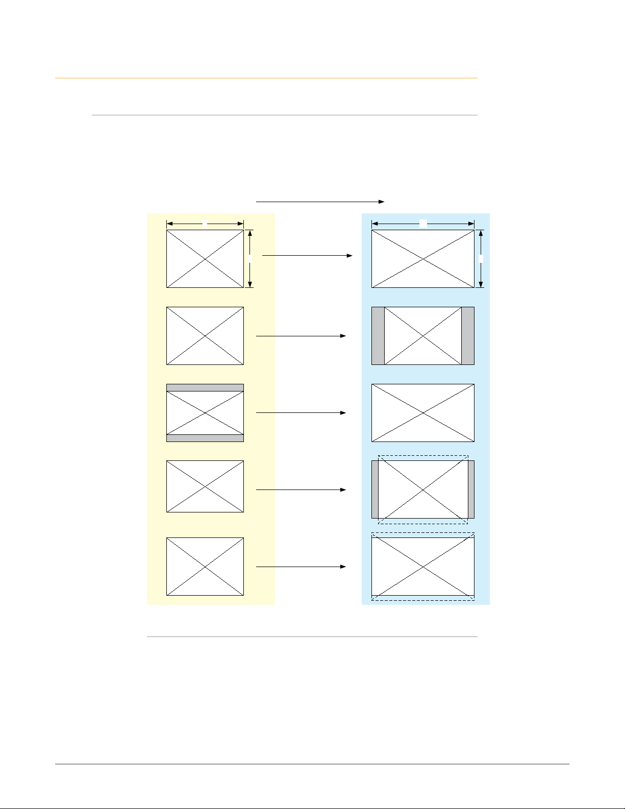
The OG-FS-Mini allows you to select the type of Upconversion performed on an
SD source input. This mode is in effect only when the input is SD (525i or 625i) and
the selected output format is HD (720p, 1080i, or 1080p).
Figure 4. Upconvert Mode Examples
Upconvert Illustrations
4:3 Upconverts To These displays on 16:9
4
Full Screen
3
4:3 Pillar
LB to Full
14:9 Pillar
16
9
Wide Zoom
Selection Description
• Full Screen – 4x3 image is stretched horizontally to ll a 16x9 frame.
• 4x3 Pillar – 4x3 image at center screen with black sidebars.
• LB to Full – 4x3 letterboxed image is scaled to t horizontally in a 16x9 frame.
Black bars top and bottom are cropped o.
• 14x9 Pillar (default) – 4x3 image is scaled to create a 14x9 image with black
sidebars and slightly cropping top and bottom of original image.
• Wide Zoom – A combination of scaling and stretching is used to t to a 16x9
frame. Slight cropping of top and bottom and a small aspect ratio change.
OG-FS-Mini Frame Synchronizer v1.5.1 9 www.aja.com
Page 10
Downconvert Mode
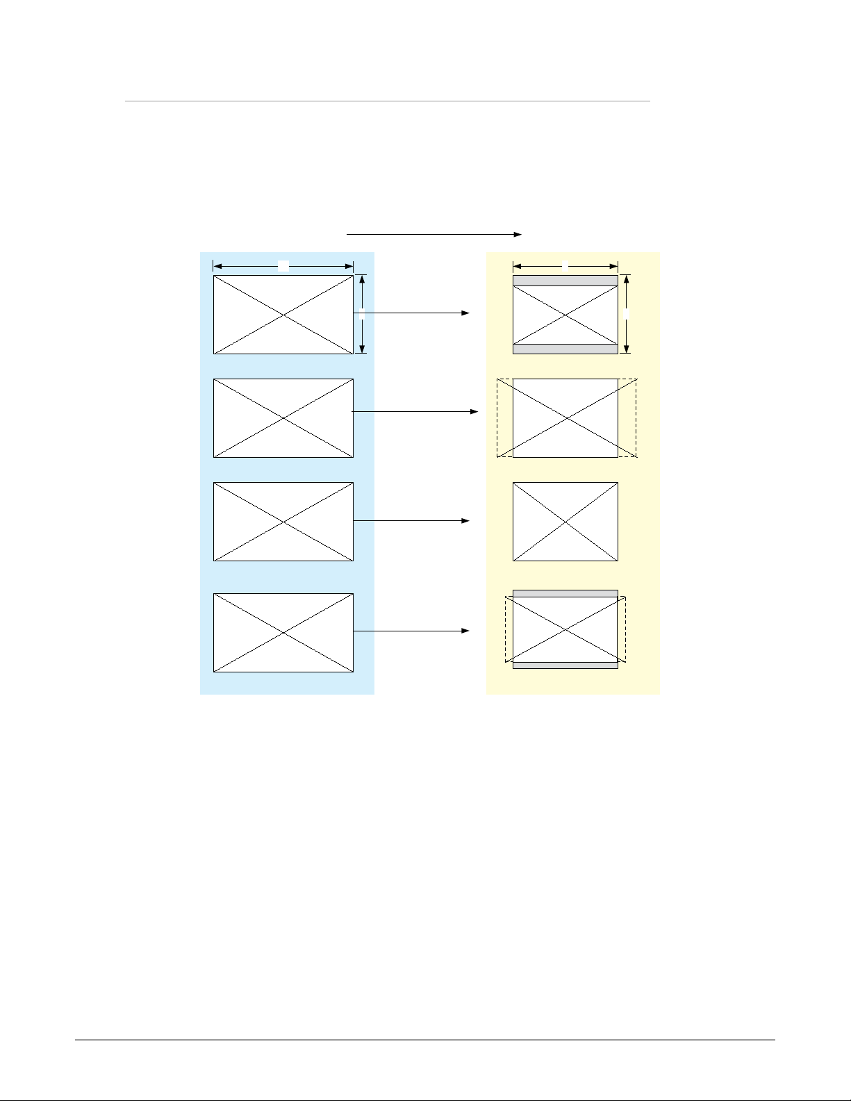
This mode determines the type of Downconversion performed on the
selected HD source input. See the following Downconvert Illustrations for
Downconversion examples. This mode is in effect only when the input is HD
(720p, 1080i, or 1080p) and the selected output format is SD (525i or 625i).
Figure 5. Downconvert Mode Example
16:9 Downconverts To These displays on 4:3
Downconvert Illustrations
16
9
4
Letterbox
3
Crop
Anamorphic
14:9
OG-FS-Mini Frame Synchronizer v1.5.1 10 www.aja.com
Page 11

Selection Description
• Letterbox – Image is reduced with black top and bottom added to image area,
with the aspect ratio preserved.
• Crop (default) – Image is cropped to t new screen size.
• Anamorphic – HD image is converted to full-screen SD with a 16x9 aspect ratio
(anamorphic).
• 14:9 – Image is reduced slightly with aspect ratio preserved. Black is added top
and bottom, and the left and right sides are cropped.
• Auto AFD – Automatically selects the best Downconvert mode based on the
input video's Active Format Description (AFD) code.
Active Format Description (AFD) codes are carried in the vertical ancillary
(VANC) portion of HD SDI video signals, specified in SMPTE 2016 as follows:
“AFD information is intended to guide DTV receivers and/or intermediate
professional video equipment regarding the display of video of one aspect
ratio on a display of another aspect ratio.”
In the OG-FS-Mini Downconverter, the AFD code on the video input can be
used to guide the Downconverter in choosing which mode to use to best
display the important content of the16:9 HD input video on the 4:3 SD output.
For example, if the input AFD code is 10 (Full Frame), it means that the input
video has important picture information throughout the full 16:9 frame, so the
Downconverter should use Letterbox mode to be sure none of the content
is cropped off. An AFD code of 9 (Pillarbox) says that the input video only has
content within the center 4:3 area of the picture (usually because it originally
came from an Upconverted SD signal) so the Downconverter Crop mode
would be the best choice. There are 16 possible HD AFD codes, of which 8 are
in common use. The OG-FS-Mini does not process or use SD AFD codes.
SD Aspect Ratio Convert
This mode selects the type of SD-to-SD Aspect Ratio Conversion (ARC) performed
on an incoming selected SD source. This mode is in effect only when the input
and output are both SD (525i or 625i). (In Europe 16:9 anamorphic video is also
known as “wide screen” video.)
OG-FS-Mini Frame Synchronizer v1.5.1 11 www.aja.com
Page 12
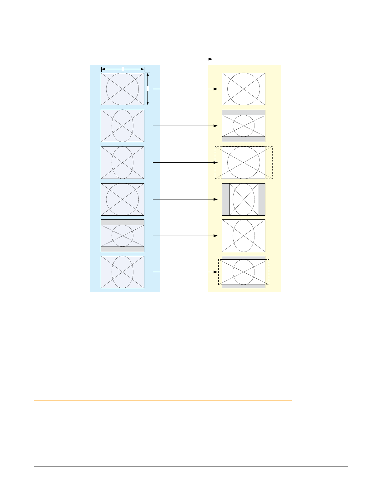
Figure 6. SD Aspect Ratio Conversion Examples
SD Aspect Ratio Conversion Illustrations
4:3 Converts To These displays on 4:3
4
3
Off
(no conversion)
Letterbox
H Crop
Pillarbox
V Crop
Selection Descriptions
User Controls
The OG-FS-Mini can be inserted right out of the box into an openGear frame
and immediately be used for many applications, since it is designed to recognize
inputs and perform standard actions automatically. However, you can also
manually configure the OG-FS-Mini using either of two methods:
14:9
• O–Turns aspect ratio conversion O.
• Letterbox–Converts 16:9 Anamorphic video to Letterbox video.
• H Crop–Converts 16:9 Anamorphic video to 4:3 Standard video (crops left and
right edges of video).
• Pillarbox–Converts 4:3 Standard video to 16:9 Anamorphic video.
• V Crop–Converts Letterbox video to 16:9 Anamorphic video.
• 14:9–Converts 16:9 Anamorphic video to 14:9 Cropped video.
• Local conguration through DIP switches on the card, or
• Remote conguration through the DashBoard Control System for an
openGear Frame.
OG-FS-Mini Frame Synchronizer v1.5.1 12 www.aja.com
Page 13
DIP Switches
The OG-FS-Mini has two DIP switch modules mounted on the card. The left
General DIP switch module can be used for general card configuration, and to
enable remote configuration using DashBoard. The right Reference DIP switch is
used for configuring the card's reference (see Figure 3 on page 6).
The General DIP switch #1 is a “Local/Remote” switch. When in “Local” mode, the
remaining DIP switches support a subset of the user controls, and DashBoard
displays only the Card and Status tabs and cannot be used for configuration.
For more details, refer to "Using DIP Switches to Control the OG-FS-Mini" on page
17.
DashBoard Control System
The DashBoard Control System, created by Ross Video, provides a control
interface between Windows, macOS and Linux computers and the cards installed
in an openGear frame. DashBoard operates through TCP/IP communication
and requires an Ethernet connection between the controlling computer and an
openGear frame.
For details about acquiring and using the DashBoard Control System, refer to
"Using the DashBoard Control System" on page 19.
Installation
Summary
Unpacking
Installing an OG-FS-Mini card into an OG-X-FR openGear frame consists of the
following steps:
• Install the Rear Panel onto the back of the frame corresponding to the slot pair
you will be using for the OG-FS-Mini card.
• Insert the OG-FS-Mini card into the frame in the right (even numbered) slot of
the pair.
• Connect the BNC, HDMI and audio cabling to the Rear Panel.
ESD Susceptibility - Static discharge can cause serious damage to sensitive
semiconductor devices. Avoid handling circuit boards in high static
environments such as carpeted areas, and when wearing synthetic ber clothing.
Always exercise proper grounding precautions when working on circuit boards
and related equipment.
Unpack each openGear product you received from the shipping container and
ensure that all items are included. If any items are missing or damaged, contact
your sales representative or AJA directly.
OG-FS-Mini Frame Synchronizer v1.5.1 13 www.aja.com
Page 14
Parts List
Quantity Description
1 OG-FS-Mini Front Card in ESD bag
1 BNC Rear Card
2 WECO mating connectors, part number
107654-00
Rear OG-FS-Mini Card Installation
1. Ensure that the frame is properly installed.
2. Locate the card frame slot on the rear of the openGear frame into which you
wish to install the openGear card.
NOTE: An OG-FS-Mini card occupies two slots in the frame.
3. Using a Phillips screwdriver, unscrew the top screw from the desired blank
rear plate and remove the rear plate.
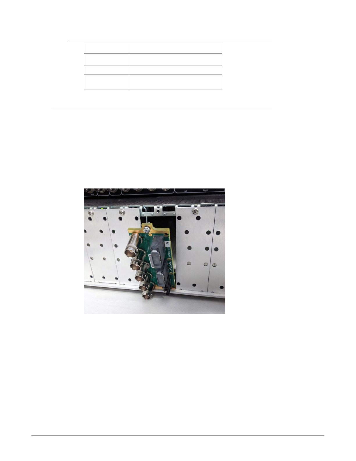
4. Seat the bottom of the Rear Card in the seating slot at the base of the frame
back plane.
Figure 7. Rear Card Inserting Into Frame Seating Slot
5. Align the top screw of the Rear Card with the screw hole on the top edge of
the frame back plane.
6. Ensure the Rear Card aligns with the desired card slot before tightening the
screw.
7. Using a Phillips screwdriver, fasten the Rear Card to the frame back plane.
Do not over tighten.
OG-FS-Mini Frame Synchronizer v1.5.1 14 www.aja.com
Page 15
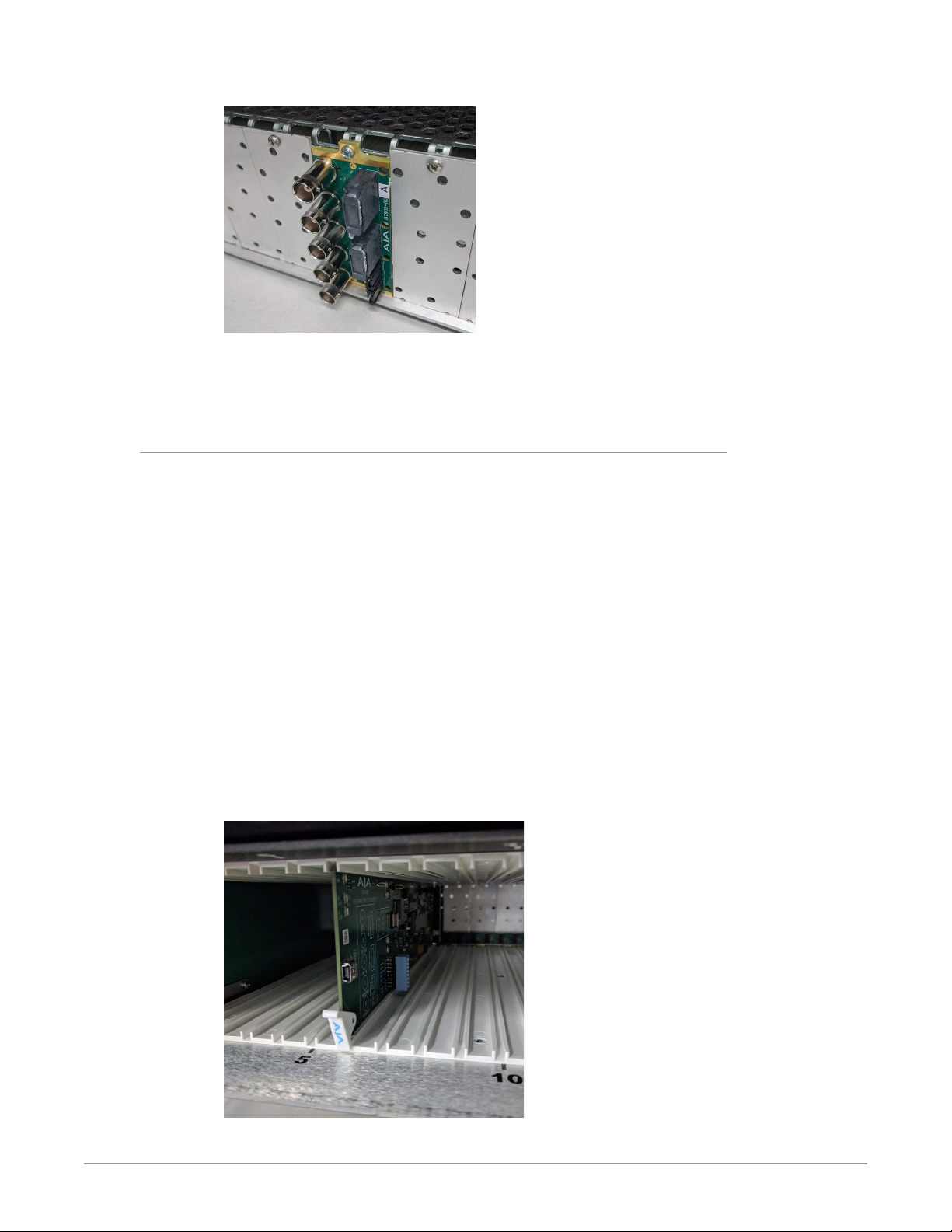
Figure 8. Rear Card Inserted Into Frame Seating Slot
8. Ensure proper frame cooling and ventilation by having all rear frame slots
covered with rear modules or blank metal plates if plates are not preinstalled.
Front OG-FS-Mini Card Installation
1. Open the openGear frame door as follows:
A. Gently pull the side door tabs towards the center of the door, releasing the
door from the frame.
B. Using both hands, pull the door towards you. The door extender arms
prevent the door from falling.
2. Locate the Rear Card you installed as described above. The interior slot
number is dependent on the slot combinations into which you installed the
Rear Card. This allows adequate spacing to avoid damaging the card, the
cards installed in the neighboring slots, or both.
3. Hold the card by the edges and carefully align the card edges with the rails
inside the frame. The slots are numbered starting from the left-most slot
when facing the frame front.
IM PORTA NT: OG-FS-Mini cards are installed into the right (even numbered) slot of the
pair in order to connect with the rear panel.
4. Fully insert the card into the frame until the card is properly seated in the
Rear Card.
Figure 9. OG-FS-Mini card
5. Close the frame door as follows:
OG-FS-Mini Frame Synchronizer v1.5.1 15 www.aja.com
inserted Into Right Slot
Page 16
Cabling
A. Slide the door into the frame.
B. Pull and release the door tabs to ensure the frame door is securely locked
to the frame.
Refer to "I/O Connections for the OG-FS-Mini" on page 6 to identify the input
and output signal connectors.
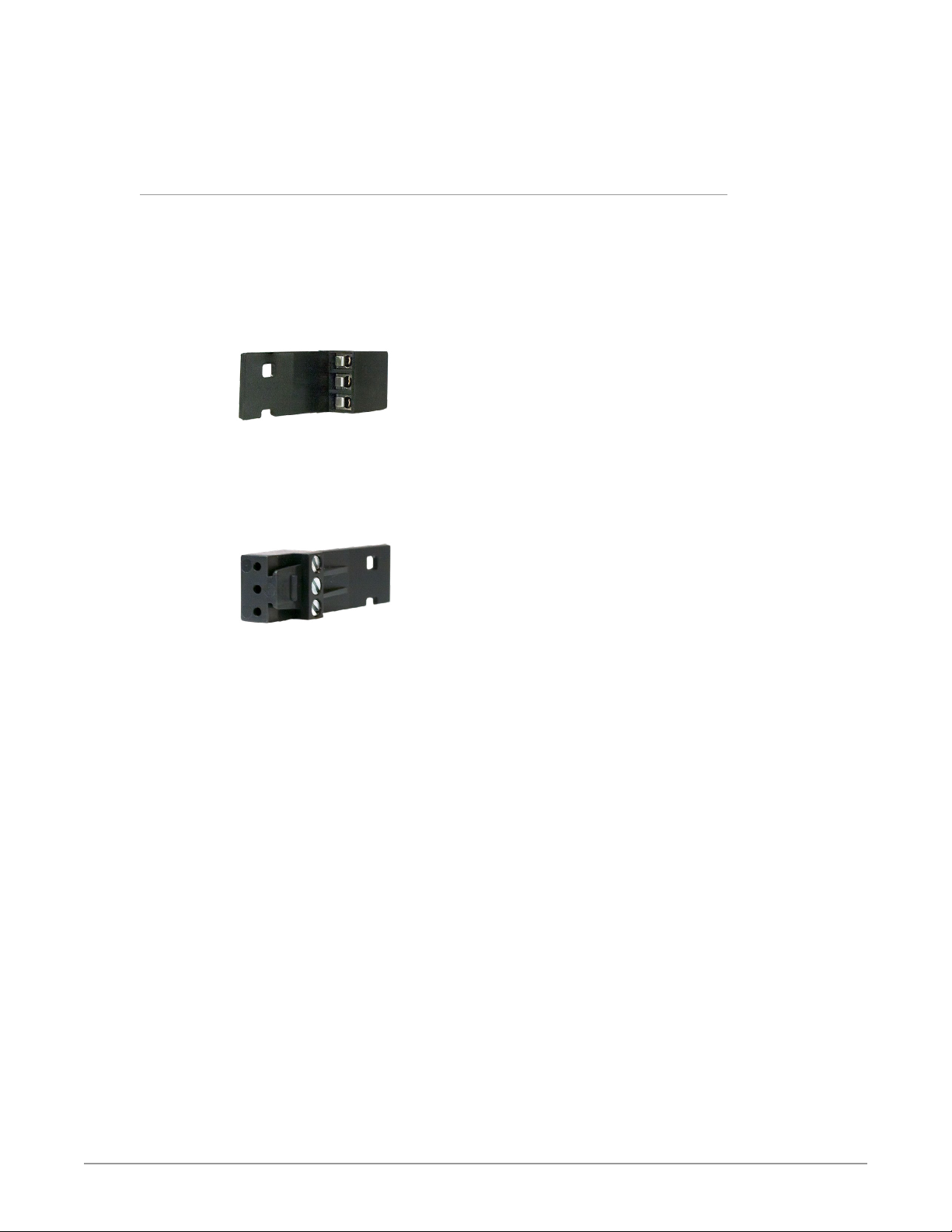
Two WECO audio mating connectors are included with each OG-FS-Mini.
1. Insert connecting audio wires into their corresponding holes from the rear
(Figure 10).
Figure 10. Rear view of the WECO mating audio connector
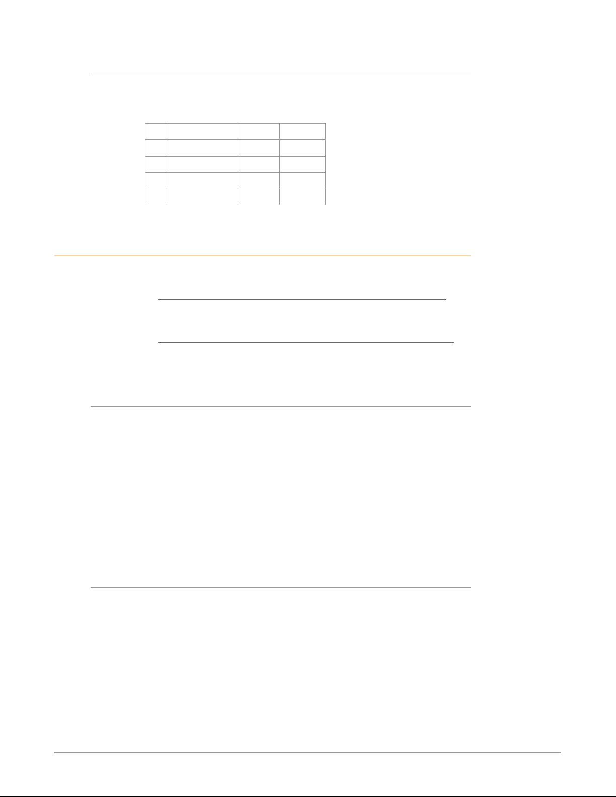
2. Tighten the screws on the other side of the audio mating connector (Figure
11).
Figure 11. Front view of the WECO mating audio connector showing the
tightening screws
3. After you have secured the wiring for each WECO mating audio connector,
connect them to the audio output connectors on the rear panel of the
OG-FS-Mini.
4. Add tie wraps around the audio connectors for strain relief.
OG-FS-Mini Frame Synchronizer v1.5.1 16 www.aja.com
Page 17

Chapter 2 – Operation
Default Operational Settings
The OG-FS-Mini converter ships from the factory with the following
configuration:
• Local (DIP switch) control (DashBoard shows status only).
• 1080i59.94 output with NTSC related inputs, or 1080i50 output with PAL
related inputs.
If these settings apply to your requirements, you can simply connect the video
and audio input and output signal cables.
For other applications, you can configure the card using its DIP switch settings, or
by setting Remote (DIP switch) control and using the DashBoard Control System
and a PC or Mac networked to an openGear frame.
Using DIP Switches to Control the OG-FS-Mini
The OG-FS-Mini has two sets of DIP switches. The first set is used for general
configuration. The second set is used only for Reference selection. See Figure 3 on
page 6.
General Configuration DIP Switches
The General DIP Switch module is located on the left side of the card.
Figure 12. General Configuration DIP Switches
1 CONTROL LOCAL REMOTE
2 SD/HD HD SD
3 1080/720 1080 720
4 FMT0 0 1
5 FMT1 0 1
6 3:2 OFF ON
7 SIDEB UP FULL
8 LTR BX DN FULL
The default DIP switch positions are all in the left position. The default settings
result in an output of 1080i59.94 with NTSC related inputs and 1080i50 with PAL
related inputs.
For 1080p 23.98/1080PsF 23.98 inputs, the input can be converted to 720p 23.98,
1080p 23.98, 1080i 59.94, or 1080p 59.94. The latter two would use the 3:2 DIP
switch to add 3:2 pulldown.
The compliance label, found on the card next to the DIP switches, lists the DIP
switch settings.
NOTE: The HDMI output does not support "PsF" formats. When the Video Output Format
is configured for PsF, the signal on the HDMI output is converted to interlace.
HDMI monitors may not support all frame rates.
OG-FS-Mini Frame Synchronizer v1.5.1 17 www.aja.com
Page 18

NOTE: OG-FS-Mini converts 3G-A formats only. It does not accept 3G-B input or produce
3G-B output.
General Configuration DIP Switch Settings
The functions of the general configuration DIP switches and what they control are
described in the following tables.
Table 1. General Configuration DIP Switch Setting Descriptions
SWITCH FUNCTION DIP Set LEFT (default) DIP Set RIGHT
1 Control Selects LOCAL (DIP),
and blocks DashBoard
conguration control.
When in “Local” mode, the
remaining DIP switches will
support a subset of the user
controls.
2 HD/SD Selects HD output mode. Selects SD output mode.
3 1080/720 (HD mode only) Selects 1080 output. Selects 720 output.
4 & 5 Alternate HD formats These two DIP switches (FMT0, FMT1) act together to select
alternate HD output formats. Zero (0) is Left position, one (1) is
Right position.
See Table 2 below for setting information.
6 3:2 Conversion (23.98/24
inputs only)
7 Up Conversion Sets upconversion to Sidebar
8 Down Conversion Sets downconversion to
3:2 conversion is OFF.
A 23.98/24 fps input results in
a 23.98/24 fps output.
(SIDEB).
Letterbox (LTRBX).
Selects REMOTE (DashBoard),
and disables DIP switches 2-8.
When in “Remote” mode,
the normal DashBoard nonvolatile registers (as last set),
control the unit.
3:2 conversion is ON.
A 23.98/24 fps input results in
either a 29.97/30 or 59.94/60
fps output.
Sets upconversion to Full
screen (FULL).
Sets downconversion to Full
screen (FULL).
DIP Switches 4 & 5 (FMT0, FMT1)
General DIP switches 4 and 5 together select alternate HD formats. Switches 1
and 2 can also affect the HD output format. In the table below an X indicates a
“Don’t Care” setting.
Table 2. Output Formats for DIP Switch 2,3, 4, & 5 Settings
SW2
HD/SD
Left Left Left Left 1080i 50/59.94/60
Left Left Left Right 1080PsF
Left Left Right Left 1080p 50/59.94/60
Left Left Right Right 1080p
Left Right X Left 720p 50/59.94/60
Left Right X Right -
Right X X X 525i/625i
OG-FS-Mini Frame Synchronizer v1.5.1 18 www.aja.com
SW3
1080/720
SW 4
FMT0
SW 5
FMT1
Output
23.98/24/25/29.97/30
23.98/24/25/29.97/30
Page 19
Reference Selection DIP Switches
The Reference DIP switch module located on the right is used only for Reference
selection.
Figure 13. Reference Selection DIP Switches
REF SELECT A B
1 Free Run O O
2 Card Ext Ref On O
3 OG Frame Ref 1 O On
4 OG Frame Ref 2 On On
Using the DashBoard Control System
The DashBoard Control System is available as a free download from the openGear
DashBoard Software Download webpage:
https://www.opengear.tv/frame-and-control/control-system/download/
Ross Video offers comprehensive documentation that covers the extensive
capabilities of the DashBoard Control System:
https://www.rossvideo.com/support/product-documentation/dashboard/
This AJA OG-FS-Mini manual addresses only those essential aspects of the
DashBoard Control System needed to control the OG-FS-Mini card.
Requirements
The DashBoard Control System requires the following components:
• openGear frame with a Frame Controller card
• Ethernet connection betweeen the controlling computer and the openGear
frame
NOTE: The openGear frame ships from AJA with the MFC-8322-S Frame Controller card
for controlling the new AJA DashBoard cards. The openGear frame also supports
the MFC-0G3-N Advanced Networking Frame Controller card, which can be used
to control compatible OG cards.
DashBoard automatically discovers openGear and DashBoard Connect devices,
such as openGear frames and cards that are present and accessible on your
network.
Control Interface Basic Components
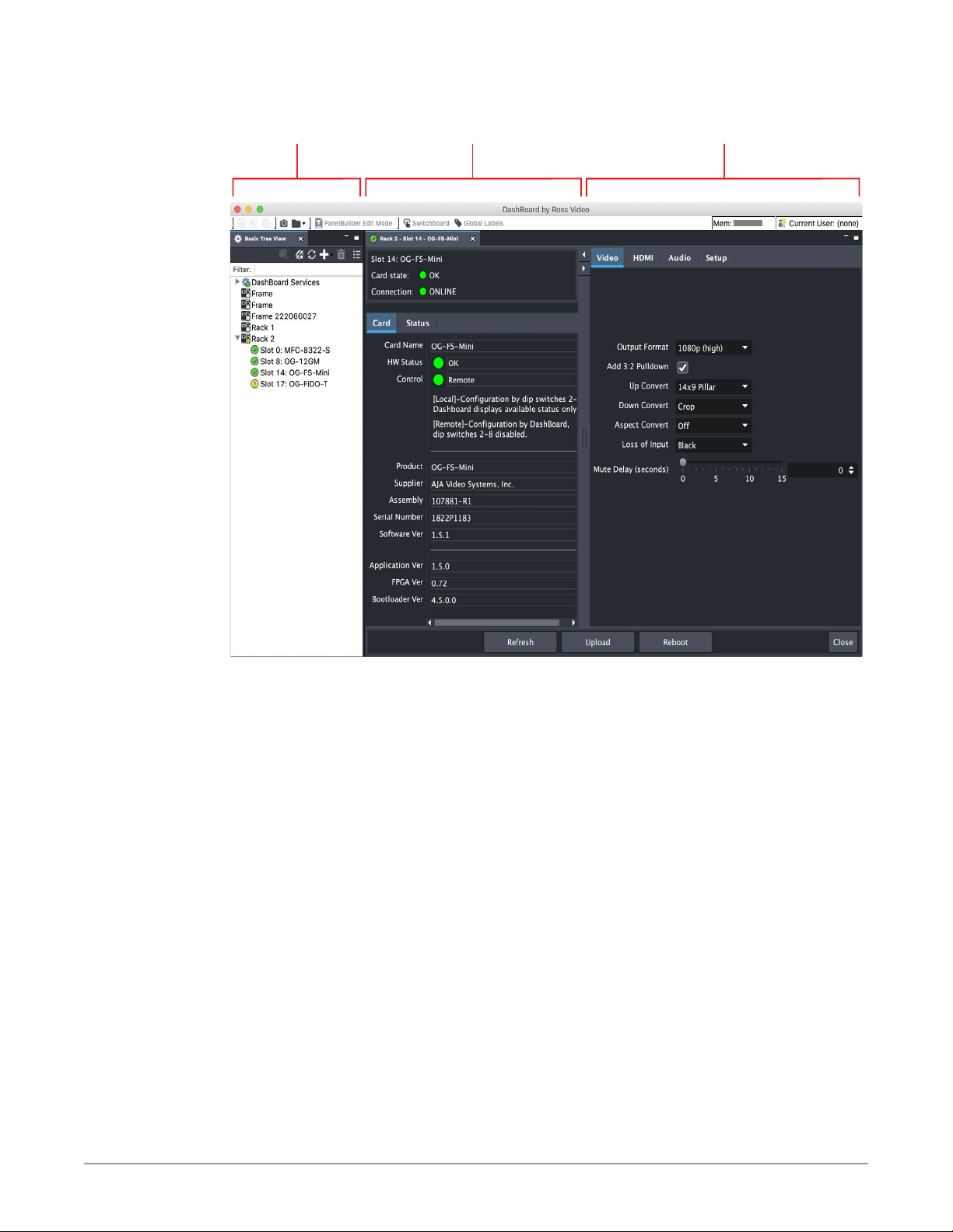
The basic components of the DashBoard Control System user interface consist of
the basic tree view of frames and cards, the card information and status panel,
and the parameter controls panel. These elements are shown below in Figure 6.
The basic tree view of frames and cards shows the frames and cards that are
discoverable by DashBoard on your network.
The card information and status panel, shown in the middle panel, display the
basic status of the card currently selected in DashBoard.
The parameter controls panel shows the tabs and parameters that the selected
card has available for configuration and control.
OG-FS-Mini Frame Synchronizer v1.5.1 19 www.aja.com
Page 20
Parameter
Controls
Card Information
and Status
Basic Tree View of
Frames and Cards
Figure 14. Main Sections of the DashBoard User Interface
OG-FS-Mini Frame Synchronizer v1.5.1 20 www.aja.com
Page 21
Card Tab Screen
Figure 15. OG-FS-Mini Card Tab Screen in DashBoard
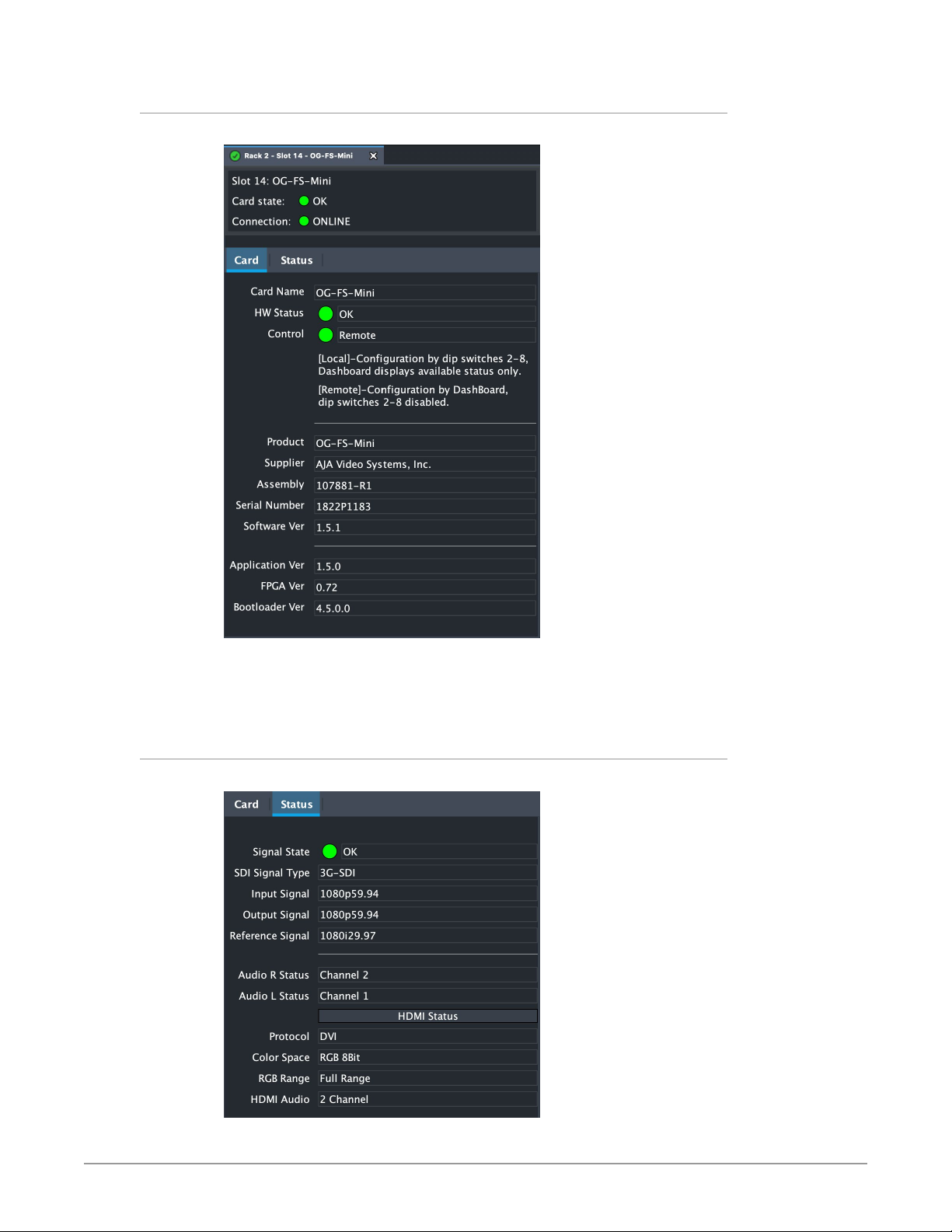
The Card tab screen indicates the basic information about the card itself such as
the card name, hardware status, control (local or remote), serial number, software
version and other items.
Status Tab Screen
Figure 16. OG-FS-Mini Status Tab Screen in DashBoard
OG-FS-Mini Frame Synchronizer v1.5.1 21 www.aja.com
Page 22
The Status tab screen indicates various signal state alarms, such as OK (green),
warning (yellow) or Not Locked (red). Additionally, for configuration parameters
that are set to "Auto" from the Video, HDMI and Audio tab screens, the
corresponding fields on the Status tab screen report their current setting.
Video Tab Screen
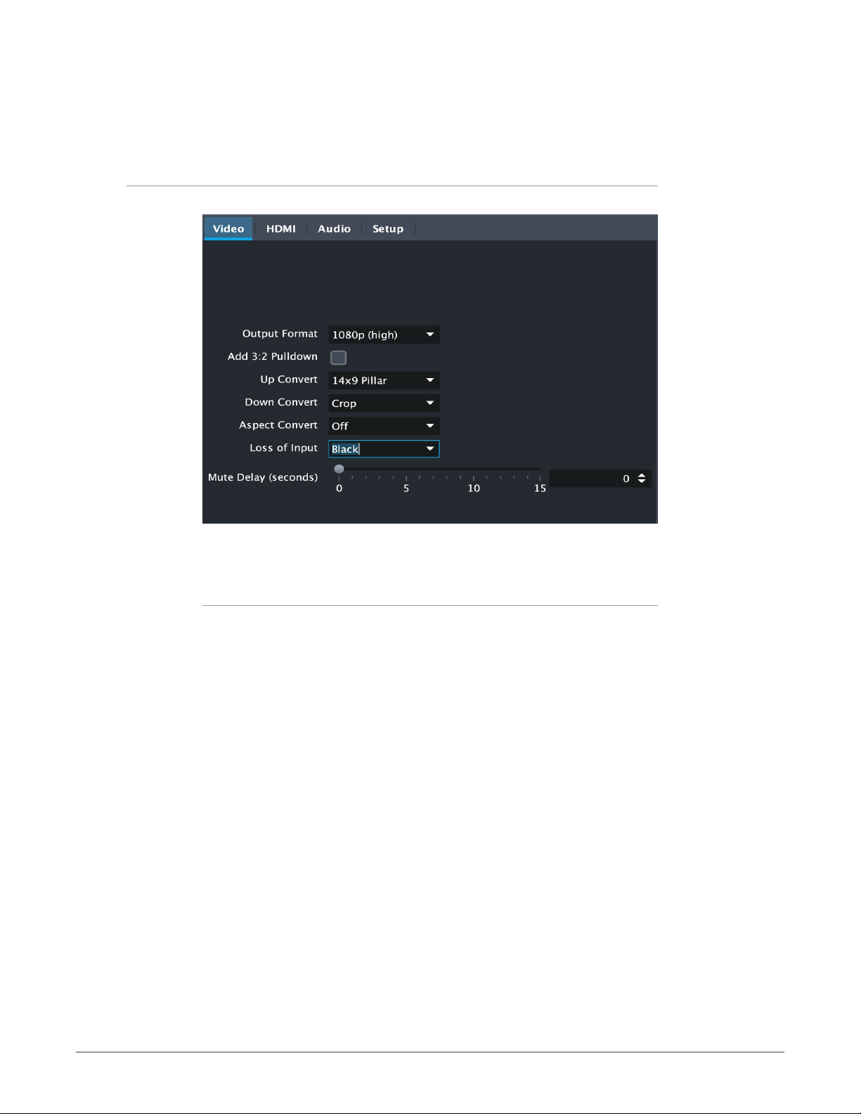
Figure 17. OG-FS-Mini Video Tab Screen in DashBoard
The Video tab screen is where you can configure OG-FS-Mini video inputs and
outputs.
Output Format
Determines the OG-FS-Mini output video format. Choose from the following
formats:
Follow INPUT - The output video format will match the format of the incoming
video.
Follow REF - The output video format will match the format of the current
Reference input.
SD - The output video format will be 525i59.94 (for 23.98, 29.97, or 59.94 fps video
inputs) or 625i50 (for 25 or 50 fps video inputs).
720p - The output video format will be 720p59.94 (for 23.98, 29.97, or 59.94 fps
video inputs), 720p60 (for 24, 30, or 60 fps video inputs), or 720p50 (for 25 or
50 fps video inputs).
1080i - The output video format will be 1080i59.94 (for 23.98, 29.97, or 59.94 fps
video inputs), 1080i60 (for 24, 30, or 60 fps video inputs), or 1080i50 (for 25 or
50 fps video inputs).
1080psf - The output video format will be 1080psf23.98 (for 23.98 fps video
inputs), 1080psf24 (for 24 fps video inputs), 1080psf25 (for 25 or 50 fps video
inputs), 1080psf29.97 (for 29.97 or 59.94 video inputs), or 1080psf30 (for 30 or
60 fps video inputs).
1080p (low) - The output video format will be 1080p23.98 (for 23.98 fps video
inputs), 1080p24 (for 24 fps video inputs), 1080p25 (for 25 or 50 fps video
inputs), 1080p29.97 (for 29.97 or 59.94 video inputs), or 1080p30 (for 30 or 60
fps video inputs).
OG-FS-Mini Frame Synchronizer v1.5.1 22 www.aja.com
Page 23

1080p (high) - The output video format will be 1080p50 (for 25 or 50 fps video
inputs), 1080p59.94 (for 23.98, 29.97 or 59.94 video inputs), or 1080p60 (for 24,
30 or 60 fps video inputs).
NOTE: OG-FS-Mini converts 3G-A formats only. It does not input or output 3G-B.
Add 3:2 Pulldown
When the Add 3:2 Pull down box is checked, 23.98 fps and 24 fps video inputs are
converted to 29.97 fps and 30 fps, respectively, by adding 3:2 pull down before
conversion. Note that this selection is only used when the OG-FS-Mini module
is in Remote mode (DIP switch #1). In Local mode, 3:2 pull down addition is
determined by DIP switch #6.
Up Convert
Determines the mode when converting from SD input video to an HD output
video format. This selection is only used when the OG-FS-Mini module is in
Remote mode (DIP switch #1). In Local mode, the up convert mode is determined
by DIP switch #7. Choose from the following:
4x3 Pillar - Produces 4x3 image at center screen with black sidebars.
14x9 Pillar (default) - Produces 14x9 image, zoomed slightly to fill a 14x9 image
with black sidebars.
Full Screen - Produces anamorphic full screen display.
LB to Full Image - Produces image zoomed to fit the full screen (letterbox).
Wide Zoom - Produces an image sized to fit a 16x9 screen using a combination of
zoom and stretch. (This can introduce a small aspect ratio change.)
Down Convert
Determines the mode when converting from HD input video to an SD output
video format. Note that this selection is only used when the OG-FS-Mini module
is in Remote mode (DIP switch #1). In Local mode, the upconvert mode is
determined by DIP switch #8. Select from the following:
Crop (default) - Image is cropped to fit new screen size.
Anamorphic - HD image is converted to full-screen SD with a 16x9 aspect ratio
(anamorphic).
14x9 - Image is reduced slightly with aspect ratio preserved. Black is added top
and bottom, and the left and right sides are cropped.
Auto AFD - Automatically selects the best Downconvert mode based on the
input video's Active Format Description (AFD) code. If the input video is not
carrying an AFD VANC code, the Downconverter defaults to crop.
Letterbox - Image is reduced with black top and bottom added to image area,
with the aspect ratio preserved.
Aspect Convert
Determines the mode when converting from SD input video to an SD output
video format. There is no DIP switch equivalent for this control. The setting
is saved in nonvolatile memory in the module and used for all subsequent
operation. Choose from the following:
Off (default) - The input image is copied to the output with no scaling.
Letterbox - The input frame is scaled vertically to a 16x9 "letterboxed" size
(anamorphic to letterbox conversion).
H Crop - The input frame is scaled horizontally to 16x9, then center-cropped
(anamorphic to center crop conversion).
OG-FS-Mini Frame Synchronizer v1.5.1 23 www.aja.com
Page 24
Pillarbox - The input frame is scaled horizontally to make a pillarbox output (4x3
to anamorphic conversion).
V Crop - The input frame is scaled vertically to make a vertically cropped output
(letterbox to anamorphic conversion).
14x9 - The input frame is scaled horizontally and vertically as a compromise
between H Crop and Letterbox (anamorphic to 14x9 conversion).
Loss of Input
Determines what action is taken when input video is lost. These are the choices:
Black (default) - The output goes to black.
Freeze - The output freezes on the last good frame.
Mute - The output will go to no-video content (no signal). This can be used in
conjunction with a downstream signal loss capability that would not have
been triggered with a black signal.
Mute Delay
If Mute is selected from the Loss of Input control above, you can set a time delay
(0-15 seconds) for how long the switch to no signal occurs. The last good frame of
video is displayed during that delay time.
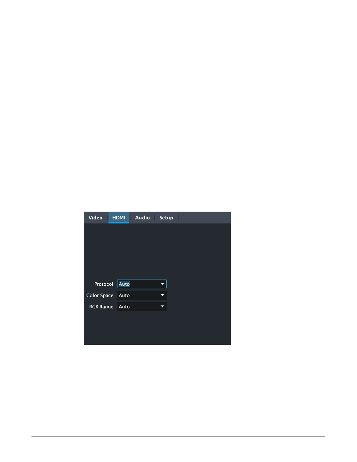
HDMI Tab Screen
Figure 18. OG-FS-Mini HDMI Tab Screen in DashBoard
Provides user selection of the HDMI output modes. There is no DIP switch
equivalent for these controls. The setting is saved in nonvolatile memory in the
module and is used for all subsequent operation.
NOTE: The HDMI video output always mirrors the SDI video output, both in content and
output format selection. Click on the Output tab to view and make changes to
the OG-FS-Mini output settings.
NOTE: When the output format is set to 1080PsF 23.98 or 1080PsF 24, the HDMI output
is converted to interlace because HDMI does not have a corresponding supported
format.
OG-FS-Mini Frame Synchronizer v1.5.1 24 www.aja.com
Page 25

Protocol
Selects whether the HDMI output uses DVI or HDMI protocols for sending video
to the destination device. Select from the following:
Auto - OG-FS-Mini automatically selects the output protocol based on getting
the attached HDMI device's EDID information. This is the recommended
setting.
HDMI - OG-FS-Mini uses HDMI protocols regardless of the attached device's EDID.
DVI - OG-FS-Mini uses DVI protocols regardless of the attached device's EDID.
Because DVI protocols do not support audio or HDMI InfoFrame ancillary data,
select this mode only if you know that the attached device requires it.
Color Space
Selects the HDMI output color space and depth. Choose from the following:
Auto - OG-FS-Mini automatically selects the mode based on getting the attached
HDMI device's EDID information. This is the recommended setting.
RGB 8Bit - OG-FS-Mini uses 8-bit RGB mode regardless of the attached device's
EDID.
RGB 10Bit - OG-FS-Mini uses 10-bit RGB mode regardless of the attached device's
EDID.
YCbCr 10Bit - OG-FS-Mini uses 10-bit YCbCr mode regardless of the attached
device's EDID.
RGB Range
Selects the HDMI video levels when the Color Space is RGB 8Bit or RGB 10Bit.
Select from the following:
Auto - The OG-FS-Mini automatically selects the mode based on getting the
attached HDMI device's EDID information. This is the recommended setting.
SMPTE - The OG-FS-Mini scales the output video level to 8-bit range 16 - 235 (10-
bit 64 - 940) regardless of the attached device's EDID.
Full Range - The OG-FS-Mini scales the output video level to 8-bit range 0 - 255
(10-bit 0 - 1023) regardless of the attached device's EDID.
OG-FS-Mini Frame Synchronizer v1.5.1 25 www.aja.com
Page 26
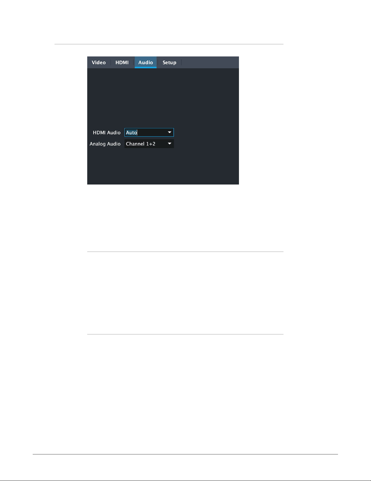
Audio Tab Screen
Figure 19. OG-FS-Mini Audio Tab Screen in DashBoard
The Audio Tab Screen is where you can configure OG-FS-Mini HDMI and analog
(RCA-style) audio output channels. There is no DIP switch equivalent for these
controls. The setting is saved in nonvolatile memory in the module and used for
all subsequent operation.
NOTE: The SDI embedded output audio is a channel-for-channel copy of the input SDI
embedded audio. There are no user controls.
HDMI Audio
Selects how many SDI channels are passed to the HDMI connector and which
channel pairs are selected. Select from the following:
Auto - The OG-FS-Mini automatically selects the audio output configuration
based on communicating with the attached HDMI device.
2 Channel - Outputs a pair of channels from the SDI stream to two channels on
the HDMI output connector. The selected audio pair is determined by the
Analog Audio setting (below).
8 Channel - Outputs SDI channels 1 through 8 to the HDMI output connector.
Analog Audio
Selects the channel pair that will be output to the Analog RCA connectors (L/R)
and the HDMI audio output (when HDMI Audio is in 2-channel mode). Choose
from the following:
Channel 1+2
Channel 3+4
Channel 5+6
Channel 7+8
Channel 9+10
Channel11+12
Channe l 13+14
Channel 15+16
OG-FS-Mini Frame Synchronizer v1.5.1 26 www.aja.com
Page 27
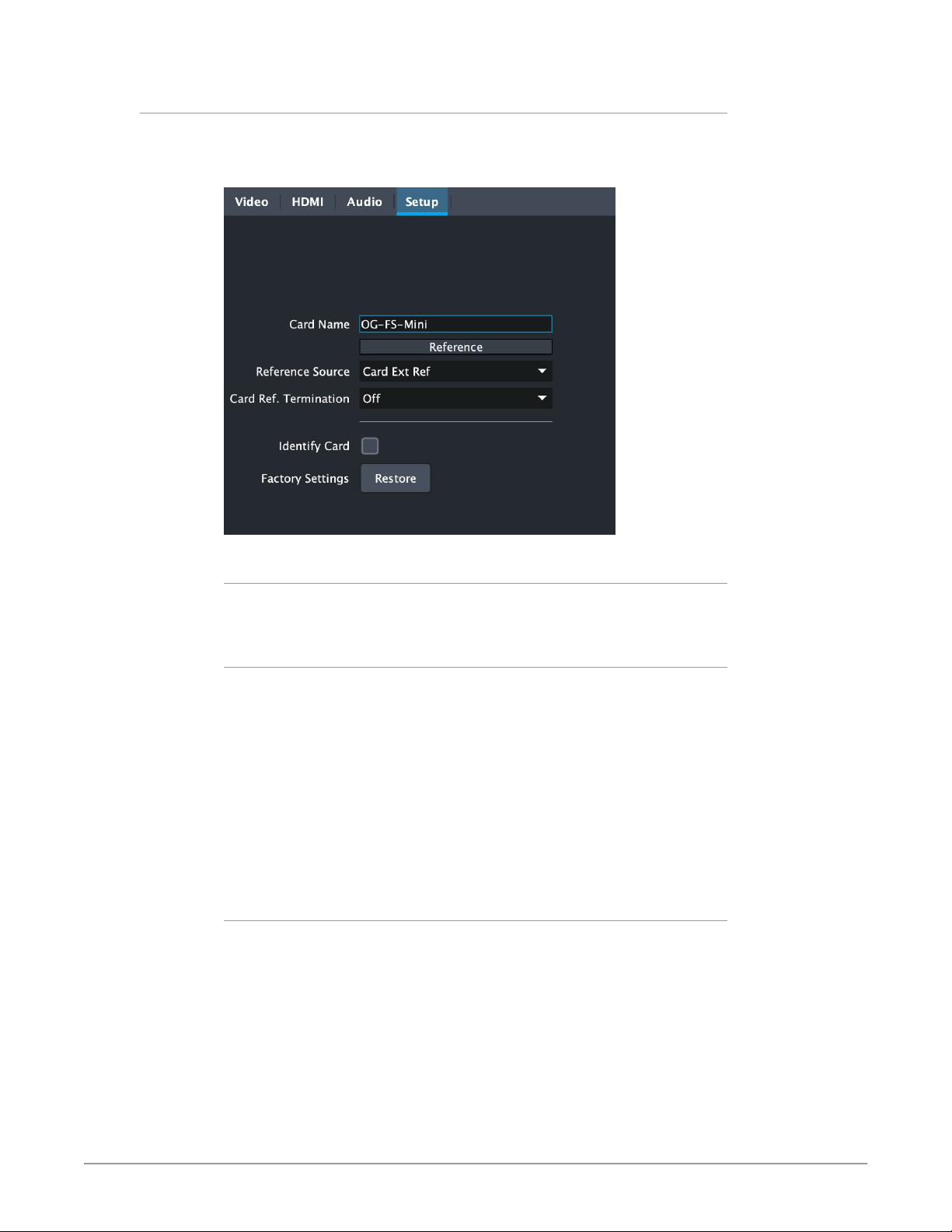
Setup Tab Screen
Click on the Setup tab to view and make changes to the card name, configure the
reference source, or to restore card settings to factory default values.
Figure 20. OG-FS-Mini Setup Tab Screen in DashBoard
Card Name
By default, this field is pre-populated with the card name OG-FS-Mini. You can
change the card name by editing the text in the Card Name field.
Reference Source
Select which source you want to use for Reference. Choose from the following:
Free Run - The OG-FS-Mini will lock to its internal clock as the reference source.
Card Ext Ref - The OG-FS-Mini will use the incoming reference source connected
to the Reference Input BNC on the rear panel of the card.
OG Frame Ref 1 - The OG-FS-Mini will use the incoming reference source
connected to the openGear frame's Reference 1 Input BNC on the rear of the
frame.
OG Frame Ref 2 - The OG-FS-Mini will use the incoming reference source
connected to the openGear frame's Reference 2 Input BNC on the rear of the
frame.
Card Ref Termination
Whether you turn this control On or Off depends on the configuration of your
equipment, and whether the incoming reference signal is high impedence or not.
For proper operation the input Reference signal must be stable and properly
terminated using a 75-ohm terminator on the last piece of downstream
equipment to which the Ref Video is connected.
On - Turn on if you have a high impedence incoming reference signal. This will
provide signal termination.
Off - Turn off (default) if you are not using a high impedence incoming reference
signal.
OG-FS-Mini Frame Synchronizer v1.5.1 27 www.aja.com
Page 28
Identify Card
Click the checkbox to turn on Identify Card. This is especially useful when working
with numerous cards and frames and you need a simple method for identifying a
specific card. Click the checkbox again to turn Identify Card off.
On - Turn on if you need to identify the card. When on, the PWR LED located at
the front top edge of the card will blink on and off with an orange/green color.
Off - Turn off (default) if you do not need to physically identify the card. When
Identify Card is off, the PWR LED light illuminates a solid green color when the
card is powered on.
Factory Settings
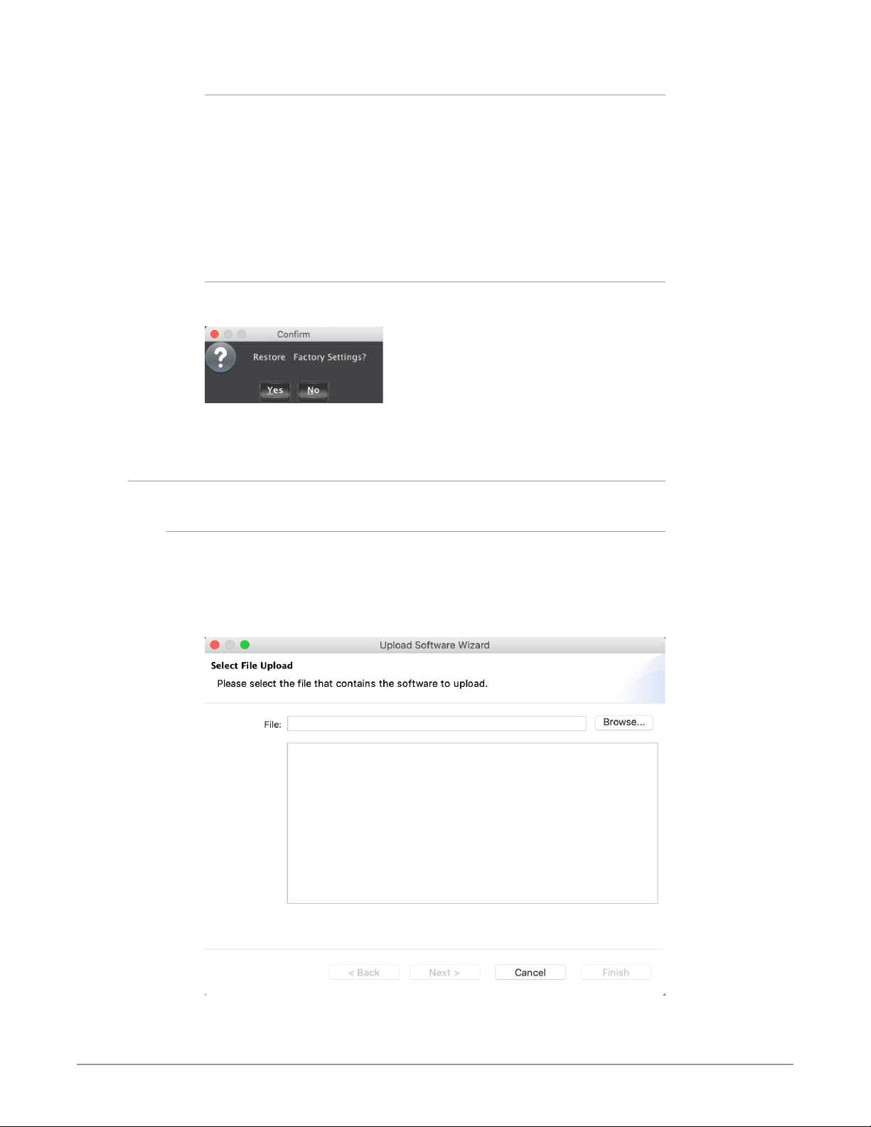
If you would like to revert the card settings to factory default values, click
Restore. A confirmation window displays.
Select Yes to restore to factory settings. Select No to cancel.
Upload Screen
To Upload New Software
1. Check the AJA website for new software for your OG-FS-Mini. If new
software is found, download it and uncompress the le archive (zip).
2. Click the Upload button in the lower panel of the DashBoard Control System
to open the Upload Software Wizard.
Figure 21. OG-FS-Mini Upload Software Wizard window in DashBoard
3. From the Upload Software Wizard window, select Browse.
OG-FS-Mini Frame Synchronizer v1.5.1 28 www.aja.com
Page 29
4. Navigate to the location of the downloaded .bin le containing the software
update. Select the .bin le, then select Open. The Upload Software Wizard
window displays characteristics of the selected le for uploading.
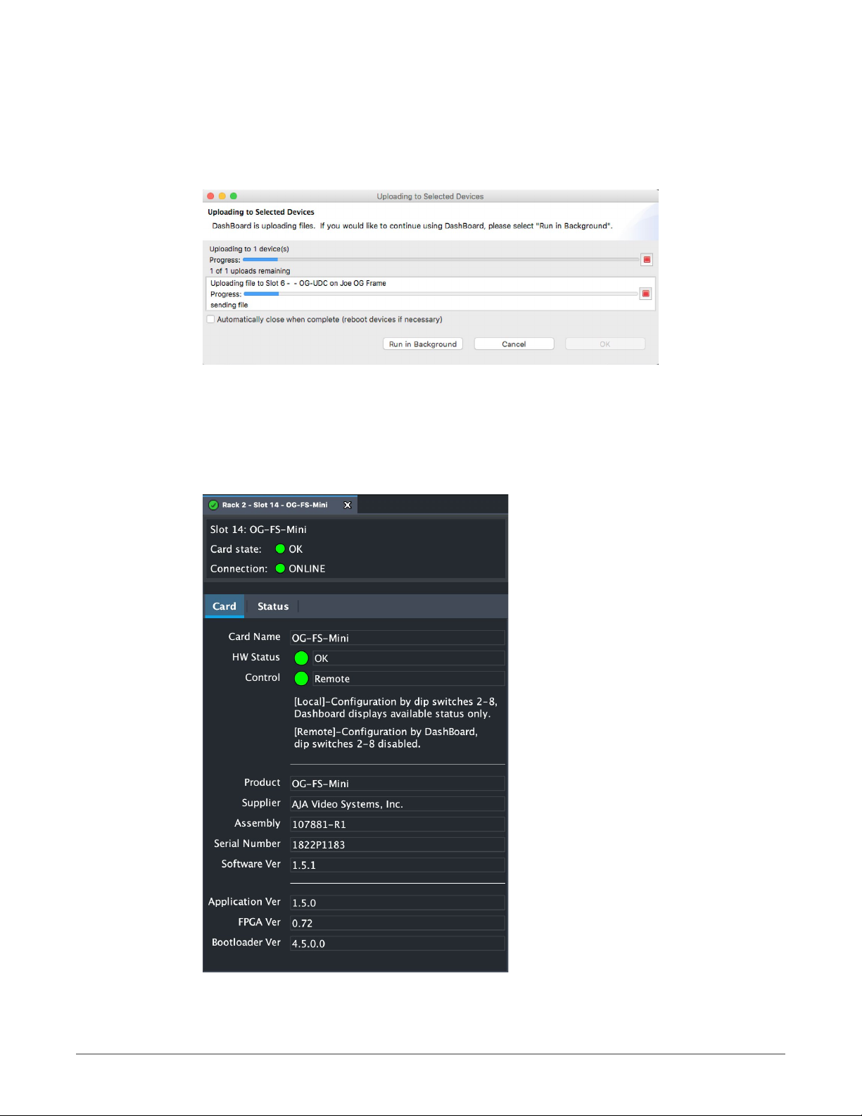
5. Click Finish. The Uploading to Selected Devices window displays with a
progress bar.
Figure 22. OG-FS-Mini Uploading to Selected Devices window in DashBoard
6. When the progress bar indicates that the uploading is nished and status
indicates "Complete," click OK.
7. To verify the version of software or rmware currently installed on your
card, select the Card tab from the center panel of DashBoard.
Figure 23. OG-FS-Mini Card Tab Screen in DashBoard indicating the currently
installed software version.
OG-FS-Mini Frame Synchronizer v1.5.1 29 www.aja.com
Page 30
Rebooting
Rebooting is a standard function built in to the DashBoard Control System, and
should only be performed if the board has become unresponsive.
WARN ING: During a reboot, all output signals are stopped for a few seconds and
conversion operations will be briefly interrupted, but will be restored once
the reboot has completed.
To Reboot the OG-FS-Mini
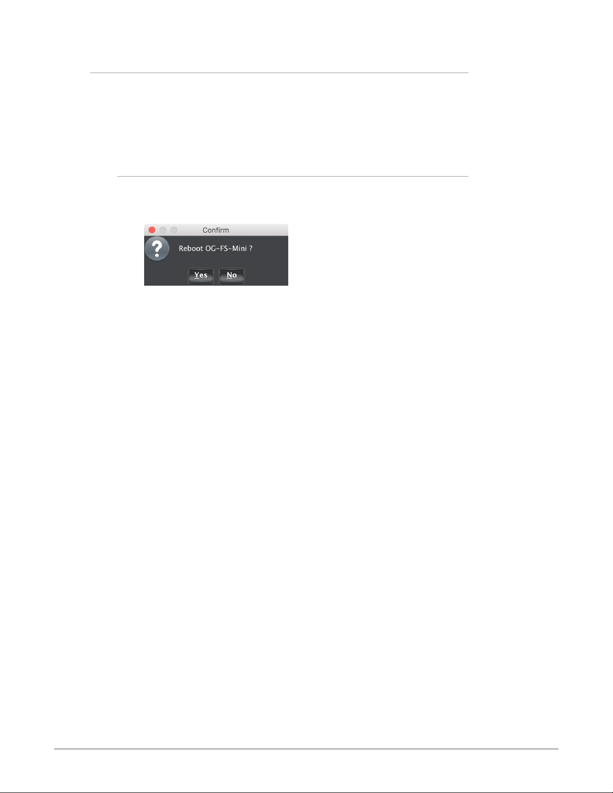
1. Click the Reboot button in the lower panel of DashBoard. The reboot
conrmation message displays.
Figure 24. Reboot confirmation window
2. Click Ye s. The message "Loading data, please wait. Refreshing device data"
displays for a moment. The card will be oine for a few seconds, and any
current conversion operations will be interrupted.
3. Following a Reboot operation, the board conguration will return to the
settings that were in place at the time of rebooting.
OG-FS-Mini Frame Synchronizer v1.5.1 30 www.aja.com
Page 31

Appendix A – Specications
OG-FS-Mini Tech Specs
Utility frame sync
Aligns and times input video to reference
Video Formats
• (HD) 1920 x 1080p
• (HD) 1920 x 1080PsF
• (HD) 1920 x 1080i
• (HD) 1280 x 720p
• (SD) 625i
• (SD) 525i
• YCbCr, 4:2:2, 10-bit
Video Input Digital
• 1x 3G-SDI, 1x BNC
• 3G/HD/SD, SMPTE-259/292/372/424
• Single Link 3G-SDI Level A, SMPTE-425-1
• (HD) 1920 x 1080p 23.98, 24, 25, 29.97, 30, 50, 59.94, 60
• (HD) 1920 x 1080PsF 23.98, 24, 25, 29.97, 30
• (HD) 1920 x 1080i 50, 59.94, 60
• (HD) 1280 x 720p 50, 59.94, 60
• (SD) 625i 50
• (SD) 525i 59.94
Video Output Digital
• 1x 3G-SDI outputs, 1x BNC
• 3G/HD/SD, SMPTE-259/292/424
• Single Link 3G-SDI Level A, SMPTE-425-1
• (HD) 1080p 23.98 (for 23.98 video inputs)
• (HD) 1080p 24 (for 24 video inputs)
• (HD) 1080p 25 (for 50 video inputs)
• (HD) 1080p 29.97 (for 59.94 video inputs)
• (HD) 1080p 30 (for 60 video inputs)
• (HD) 1080p 50 (for 50 video inputs)
• (HD) 1080p 59.94 (for 23.98, 59.94 video inputs)
• (HD) 1080p 60 (for 24, 30 or 60 video inputs)
• (HD) 1080PsF 23.98 (for 23.98 video inputs)
• (HD) 1080PsF 24 (for 24 video inputs)
• (HD) 1080PsF 25 (for 50 video inputs)
• (HD) 1080PsF 29.97 (for 59.94 video inputs)
• (HD) 1080Psf 30 (for 30 or 60 video inputs)
• (HD) 1080i 59.94 (for 23.98, or 59.94 video inputs)
• (HD) 1080i 60 (for 24, 30, or 60 video inputs)
• (HD) 1080i 50 (for 25 or 50 video inputs)
• (HD) 720p 50 (for 50 video inputs)
OG-FS-Mini Frame Synchronizer v1.5.1 31 www.aja.com
Page 32

• (HD) 720p 59.94 (for 23.98, 59.94 video inputs)
• (HD) 720p 60 (for 24, 30, or 60 video inputs)
• (SD) 625i 50 (for 25 or 50 fps video inputs)
• (SD) 525i 59.94 (for 23.98 or 59.94 video inputs)
Monitor Output Digital
• 1x HDMI standard type A connector
• HD/SD
• Color space, YCbCr or RGB
• Bit depth, 8 or 10
• RGB Range, SMPTE or Full Range
Video Processing
• Frame rate conversion/lm cadence removal/insertion (3:2)
• Freeze (on input signal loss) to black or last good frame
• AFD input detection, down-convert control
• Nominal video delay HD/SD, 1 frame
Up-Conversion
• Hardware 10-bit
• 4x3 Pillar: results in a 4x3 image at center screen with black sidebars
• 14x9 Pillar: results in a 4x3 image zoomed slightly to ll a 14x9 image with
black side bars
• Full Screen: results in a 4x3 image stretched horizontally to ll in a 16x9 screen
• Letterbox to Full: results in image zoomed to ll fullscreen
• Wide Zoom: results in a combination of zoom and horizontal stretch to ll a
16x9 screen; this setting will introduce a small aspect ratio change
Down-Conversion
• Hardware 10-bit
• Crop: image is cropped to t new screen size
• Anamorphic: HD image is converted to full-screen SD with a 16x9 aspect ratio
• 14x9: image is reduced slightly with aspect ratio preserved, black is added top
and bottom, and the left and right sides are cropped
• Auto AFD: automatically selects the best down-convert mode based on the
input video's Active Format Description (AFD) code
• Letterbox: image is reduced with black top and bottom added to image area
with the aspect ratio preserved
Cross-Conversion
• Hardware 10-bit
• 1080i to 720p
• 720p to 1080i
• 720p to 1080PsF
Aspect Ratio Conversion for SD to SD
• Letterbox: transforms SD anamorphic material to a letterboxed image
• H Crop: produces a horizontally stretched eect on the image; transforms
anamorphic SD to full frame
• SD Pillarbox: produces an image in the center of the screen with black borders
on the left and right sides and an anamorphized image in the center
• V Crop: transforms SD letterbox material to an anamorphic image
• 14x9: anamorphic to 14x9 conversion
OG-FS-Mini Frame Synchronizer v1.5.1 32 www.aja.com
Page 33

Audio Input Digital
• 48 kHz sample rate
• 1x SDI embedded input
• 16-channels, 24-bit (20-bit SD), SMPTE-272/299
Audio Output Digital
• 48 kHz sample rate
• 1x SDI embedded output
• 16-channels, 24-bit (20-bit SD), SMPTE-272/299
Audio I/O
• 16-channel embedded SDI audio input
• 16-channel embedded SDI audio output
• 8-channel HDMI audio output
• Balanced analog audio outputs, 2x 3-Pin terminal block connectors
Ancillary Data
• Supports pass-through of PCM embedded audio
• Supports pass-through of non-PCM audio when source is in time with the
selected ref (SDI In or Ext Ref). Non-PCM audio is not supported during frame
sync operation.
• All other ANC data is not passed
Reference Input
• Supported reference video inputs include:
• 75-ohm terminating
Genlock
• Lock to External Reference
• Lock to SDI input
• Free run
HDCP
• The OG-FS-Mini does not encode the HDMI output with HDCP encryption.
User Interface
• External DIP switch
• openGear DashBoard network control software via Windows, macOS or Linux
• 1080i tri-level sync
• 1080p tri-level sync
• 720p tri-level sync
• 625i Color Black
• 525i Color Black
By denition, HD-SDI inputs to the OG-FS-Mini are unencrypted. The HDMI
specication requires HDMI monitors to support unencrypted inputs.
Size
• openGear standard form factor, front slot and rear card. Two slots required for
each card
Weight
• 0.5 lb (0.3 kg)
OG-FS-Mini Frame Synchronizer v1.5.1 33 www.aja.com
Page 34

Power
Environment
• openGear frame compatible, 7.0 watts max per card
• Safe Operating Temperature: 0 to 40 C (32 to 104 F)
• Safe Storage Temperature (Power OFF): -40 to 60 C (-40 to 140 F)
• Operating Relative Humidity: 10-90% noncondensing
• Operating Altitude: <3,000 meters (<10,000 feet)
OG-FS-Mini Frame Synchronizer v1.5.1 34 www.aja.com
Page 35

Appendix B – Safety and Compliance
Federal Communications Commission (FCC) Compliance Notices
Class A Interference Statement
This equipment has been tested and found to comply with the limits for a Class
A digital device, pursuant to Part 15, Subpart B of the FCC Rules. These limits
are designed to provide reasonable protection against harmful interference
in a residential installation. This equipment generates, uses, and can radiate
radio frequency energy and, if not installed and used in accordance with the
instructions, may cause harmful interference to radio communications. However,
there is no guarantee that interference will not occur in a particular installation. If
this equipment does cause harmful interference to radio or television reception,
which can be determined by turning the equipment off and on, the user is
encouraged to try to correct the interference by one or more of the following
measures:
• Reorient or relocate the receiving antenna.
• Increase the separation between the equipment and receiver.
• Connect the equipment into an outlet on a circuit dierent from that to which
the receiver is connected.
• Consult the dealer or an experienced radio/TV technician for help.
FCC Caution
This device complies with Part 15 of the FCC Rules. Operation is subject to the
following two conditions: (1) This device may not cause harmful interference, and
(2) this device must accept any interference received, including interference that
may cause undesired operation.
Canadian ICES Statement
Canadian Department of Communications Radio Interference Regulations
This digital apparatus does not exceed the Class A limits for radio-noise emissions
from a digital apparatus as set out in the Radio Interference Regulations of
the Canadian Department of Communications. This Class A digital apparatus
complies with Canadian ICES-003.
Règlement sur le brouillage radioélectrique du ministère des Communications
Cet appareil numérique respecte les limites de bruits radioélectriques visant les
appareils numériques de classe A prescrites dans le Règlement sur le brouillage
radioélectrique du ministère des Communications du Canada. Cet appareil
numérique de la Classe A est conforme à la norme NMB-003 du Canada.
European Union and European Free Trade Association (EFTA)
Regulatory Compliance
This equipment may be operated in the countries that comprise the member
countries of the European Union and the European Free Trade Association. These
countries, listed in the following paragraph, are referred to as The European
Community throughout this document:
AUSTRIA, BELGIUM, BULGARIA, CYPRUS, CZECH REPUBLIC, DENMARK, ESTONIA,
FINLAND, FRANCE, GERMANY, GREECE, HUNGARY, IRELAND, ITALY, LATVIA,
LITHUANIA, LUXEMBOURG, MALTA, NETHERLANDS, POLAND, PORTUGAL,
ROMANIA, SLOVAKIA, SLOVENIA, SPAIN, SWEDEN, UNITED KINGDOM, ICELAND,
LICHTENSTEIN, NORWAY, SWITZERLAND
OG-FS-Mini Frame Synchronizer v1.5.1 35 www.aja.com
Page 36
Declaration of Conformity
Marking by this symbol indicates compliance with the Essential Requirements of
the EMC Directive of the European Union 2014/30/EU.
This equipment meets the following conformance standards:
Safety
EN 60065: 2014 (T-Mark License),
IEC 60065: 2014 (CB Scheme Report/Certificate)
Additional licenses issued for specific countries available on request.
Emissions
EN 55032: 2012 + AC: 2013, CISPR 32: 2015,
EN 61000-3-2: 2014, EN 61000-3-3: 2013
Immunity
EN 55103-2: 2009, EN 61000-4-2:2009, EN 61000-4-3: 2006 + A1:2008 + A2:2010,
EN 61000-4-4: 2004 + A1:2010, EN 61000-4-5:2006, EN 61000-4-6:2009,
EN 61000-4-11:2004
Environments: E2, E3 and E4
The product is also licensed for additional country specific standards as required
for the International Marketplace.
Warning! This is a Class A product. In a domestic environment, this product
may cause radio interference, in which case, the user may be required to take
appropriate measures.
Achtung! Dieses ist ein Gerät der Funkstörgrenzwertklasse A. In Wohnbereichen
können bei Betrieb dieses Gerätes Rundfunkstörungen auftreten, in welchen
Fällen der Benutzer für entsprechende Gegenmaßnahmen verantwortlich ist.
Attention! Ceci est un produit de Classe A. Dans un environnement domestique,
ce produit risque de créer des interférences radioélectriques, il appartiendra
alors à l?utilisateur de prendre les mesures spéciques appropriées..
Recycling Notice
This symbol on the product or its packaging indicates that this product
must not be disposed of with your other household waste. Instead, it is your
responsibility to dispose of your waste equipment by handing it over to a
designated collection point for the recycling of waste electrical and electronic
equipment. The separate collection and recycling of your waste equipment
at the time of disposal will help conserve natural resources and ensure that
it is recycled in a manner that protects human health and the environment.
For more information about where you can drop o your waste for recycling,
please contact your local authority, or where you purchased your product.
OG-FS-Mini Frame Synchronizer v1.5.1 36 www.aja.com
Page 37
Korea KCC Compliance Statement
넩 韥韥鱉 꽺ꓩ끞 쀍陲꾅 ꩡ끞뼕 ꑞ놶냱ꈑ 놶뼞ꫦ뵾閵ꌱ ꗐ냵 韥韥ꈑ 閵뇊
ꩡ 끞 녅 껽 驩 ꓭ
끞 쀍陲꾅 ꩡ끞뼍鱉 陲끥 놹볁閹ꫢ넍 끥ꇙ閵 넽걪鱽鲙.
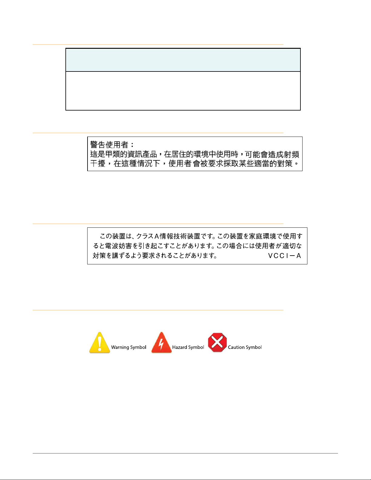
Taiwan Compliance Statement
This is a Class A product based on the standard of the Bureau of Standards,
Metrology and Inspection (BSMI) CNS 13438, Class A. In a domestic environment
this product may cause radio interference in which case the user may be required
to take adequate measures.
Japan Compliance Statement
This is a Class A product based on the standard of the VCCI Council (VCCI32:2016).
If this equipment is used in a domestic environment, radio interference may
occur, in which case, the user may be required to take corrective actions.
Translated Warning and Caution Messages
The following caution statements, warning conventions, and warning messages
apply to this product and manual.
OG-FS-Mini Frame Synchronizer v1.5.1 37 www.aja.com
Page 38
Before Operation Please Read These Instructions
Warning! Read and follow all warning notices and instructions marked on the
product or included in the documentation.
Avertissement! Lisez et conformez-vous à tous les avis et instructions
d'avertissement indiqués sur le produit ou dans la documentation.
Warnung! Lesen und befolgen Sie die Warnhinweise und Anweisungen, die auf
dem Produkt angebracht oder in der Dokumentation enthalten sind.
¡Advertencia! Lea y siga todas las instrucciones y advertencias marcadas en el
producto o incluidas en la documentación.
Aviso! Leia e siga todos os avisos e instruções assinalados no produto ou incluídos
na documentação.
Avviso! Leggere e seguire tutti gli avvisi e le istruzioni presenti sul prodotto o
inclusi nella documentazione.
Warning! Do not use this device near water and clean only with a dry cloth.
Avertissement! N'utilisez pas cet appareil près de l'eau et nettoyez-le seulement
avec un tissu sec.
Warnung! Das Gerät nicht in der Nähe von Wasser verwenden und nur mit einem
trockenen Tuch säubern.
¡Advertencia! No utilice este dispositivo cerca del agua y límpielo solamente con
un paño seco.
Aviso! Não utilize este dispositivo perto da água e limpe-o somente com um pano
seco.
Avviso! Non utilizzare questo dispositivo vicino all'acqua e pulirlo soltanto con un
panno asciutto.
Warning! Do not block any ventilation openings. Install in accordance with the
manufacturer's instructions.
Avertissement! Ne bloquez aucune ouverture de ventilation. Suivez les
instructions du fabricant lors de l'installation.
Warnung! Die Lüftungsönungen dürfen nicht blockiert werden. Nur gemäß den
Anweisungen des Herstellers installieren.
¡Advertencia! No bloquee ninguna de las aberturas de la ventilación. Instale de
acuerdo con las instrucciones del fabricante.
Aviso! Não obstrua nenhuma das aberturas de ventilação. Instale de acordo com as
instruções do fabricante.
Avviso! Non ostruire le aperture di ventilazione. Installare in conformità con le
istruzioni del fornitore.
Warning! Do not install near any heat sources such as radiators, heat registers,
stoves, or other apparatus (including ampliers) that produce heat.
Avertissement! N'installez pas l'appareil près d'une source de chaleur telle que des
radiateurs, des bouches d'air de chauage, des fourneaux ou d'autres appareils
(amplicateurs compris) qui produisent de la chaleur.
Warnung! Nicht in der Nähe von Wärmequellen wie Heizkörpern, Heizregistern,
Öfen oder anderen Wärme erzeugenden Geräten (einschließlich Verstärkern)
aufstellen.
¡Advertencia! No instale cerca de fuentes de calor tales como radiadores, registros
de calor, estufas u otros aparatos (incluidos amplicadores) que generan calor.
Aviso! Não instale perto de nenhuma fonte de calor tal como radiadores, saídas de
calor, fogões ou outros aparelhos (incluindo amplicadores) que produzam calor.
Avviso! Non installare vicino a fonti di calore come termosifoni, diusori di aria
calda, stufe o altri apparecchi (amplicatori compresi) che emettono calore
OG-FS-Mini Frame Synchronizer v1.5.1 38 www.aja.com
Page 39
Warning! Do not defeat the safety purpose of the polarized or grounding-
type plug. A polarized plug has two blades with one wider than the other. A
grounding type plug has two blades and a third grounding prong. The wide
blade or the third prong are provided for your safety. If the provided plug does
not t into your outlet, consult an electrician for replacement of the obsolete
outlet.
Avertissement! La sécurité de la prise polarisée ou de la prise de type mise à la
terre ne doit en aucun cas être empêchée de fonctionner. Une prise polarisée
a deux broches, l'une étant plus large que l'autre. Une prise de type mise à la
terre a deux broches et une troisième broche pour la mise à la terre. La broche
large ou la troisième broche sont fournies pour votre sécurité. Si la prise
fournie ne s'insère pas dans votre prise femelle, consultez un électricien pour le
remplacement de la prise femelle obsolète.
Warnung! Der Sicherheitszweck des gepolten bzw. Schukosteckers ist zu
berücksichtigen. Ein gepolter Stecker verfügt über zwei Pole, von denen einer
breiter als der andere ist. Ein Schukostecker verfügt neben den zwei Polen noch
über einen dritten Pol zur Erdung. Der breite Pol bzw. der Erdungspol dienen der
Sicherheit. Wenn der zur Verfügung gestellte Stecker nicht in Ihren Anschluss
passt, konsultieren Sie einen Elektriker, um den veralteten Anschluss zu ersetzen.
¡Advertencia! No eche por tierra la nalidad del tipo de enchufe polarizado con
conexión a tierra. Un enchufe polarizado tiene dos espigas, una más ancha
que la otra. Un enchufe con conexión a tierra tiene dos espigas iguales y una
tercera espiga que sirve para la conexión a tierra. La expiga ancha, o la tercera
espiga, sirven para su seguridad. Si el enchufe suministrado no encaja en el
tomacorriente, consulte con un electricista para reemplazar el tomacorriente
obsoleto.
Aviso! Não anule a nalidade da segurança da cha polarizada ou do tipo ligação
terra. Uma cha polarizada tem duas lâminas sendo uma mais larga do que
a outra. Uma cha do tipo de ligação à terra tem duas lâminas e um terceiro
terminal de ligação à terra. A lâmina larga ou o terceiro terminal são fornecidos
para sua segurança. Se a cha fornecida não couber na sua tomada, consulte um
electricista para a substituição da tomada obsoleta.
Avviso! Non compromettere la sicurezza della spina polarizzata o con messa a
terra. Una spina polarizzata ha due spinotti, di cui uno più largo. Una spina con
messa a terra ha due spinotti e un terzo polo per la messa a terra. Lo spinotto
largo o il terzo polo sono forniti per motivi di sicurezza. Se la spina fornita non
si inserisce nella presa di corrente, contattare un elettricista per la sostituzione
della presa obsoleta.
Warning! Since the Mains plug is used as the disconnection for the device, it must
remain readily accessible and operable.
Avertissement! Puisque la prise principale est utilisée pour débrancher l'appareil,
elle doit rester aisément accessible et fonctionnelle.
Warnung! Da der Netzstecker als Trennvorrichtung dient, muss er stets zugänglich
und funktionsfähig sein.
¡Advertencia! Puesto que el enchufe de la red eléctrica se utiliza como dispositivo
de desconexión, debe seguir siendo fácilmente accesible y operable.
Aviso! Dado que a cha principal é utilizada como a desconexão para o dispositivo,
esta deve manter-se prontamente acessível e funcional.
Avviso! Poiché il cavo di alimentazione viene usato come dispositivo di
sconnessione, deve rimane prontamente accessibile e operabile.
OG-FS-Mini Frame Synchronizer v1.5.1 39 www.aja.com
Page 40
Warning! Protect the power cord from being walked on or pinched particularly at
plugs, convenience receptacles, and the point where they exit from the device.
Avertissement! Protégez le cordon d'alimentation pour que l'on ne marche
pas dessus ou qu'on le pince, en particulier au niveau des prises mâles, des
réceptacles de convenance, et à l'endroit où il sort de l'appareil.
Warnung! Vermeiden Sie, dass auf das Netzkabel getreten oder das Kabel geknickt
wird, insbesondere an den Steckern, den Steckdosen und am Kabelausgang am
Gerät.
¡Advertencia! Proteja el cable de energía para que no se le pise ni apriete, en
especial cerca del enchufe, los receptáculos de conveniencia y el punto del que
salen del equipo.
Aviso! Proteja o cabo de alimentação de ser pisado ou de ser comprimido
particularmente nas chas, em tomadas de parede de conveniência e no ponto
de onde sai do dispositivo.
Avviso! Proteggere il cavo di alimentazione in modo che nessuno ci cammini sopra
e che non venga schiacciato soprattutto in corrispondenza delle spine e del
punto in cui esce dal dispositivo.
Warning! Unplug this device during lightning storms or when unused for long
periods of time.
Avertissement! Débranchez cet appareil pendant les orages avec éclairsou s'il est
inutilisé pendant de longues périodes.
Warnung! Das Gerät ist bei Gewitterstürmen oder wenn es über lange Zeiträume
ungenutzt bleibt vom Netz zu trennen.
¡Advertencia! Desenchufe este dispositivo durante tormentas eléctricas o cuando
no se lo utilice por largos periodos del tiempo.
Aviso! Desconecte este dispositivo da tomada durante trovoadas ou quando não é
utilizado durante longos períodos de tempo.
Avviso! Utilizzare soltanto i collegamenti e gli accessori specicati e/o venduti dal
produttore, quali il treppiedi e l'esoscheletro.
OG-FS-Mini Frame Synchronizer v1.5.1 40 www.aja.com
Page 41
Warning! Refer all servicing to qualied service personnel. Servicing is required
when the device has been damaged in any way, such as power-supply cord or
plug is damaged, liquid has been spilled or objects have fallen into the device,
the device has been exposed to rain or moisture, does not operate normally, or
has been dropped.
Avertissement! Référez-vous au personnel de service qualié pour tout entretien.
L'entretien est exigé quand l'appareil a été endommagé de quelque manière
que ce soit, par exemple lorsque le cordon d'alimentation ou la prise sont
endommagés, que du liquide a été versé ou des objets sont tombés dans
l'appareil, que l'appareil a été exposé à la pluie ou à l'humidité, ne fonctionne pas
normalement ou est tombé.
Warnung! Das Gerät sollte nur von qualizierten Fachkräften gewartet werden.
Eine Wartung ist fällig, wenn das Gerät in irgendeiner Weise beschädigt wurde,
wie bei beschädigtem Netzkabel oder Netzstecker, falls Flüssigkeiten oder
Objekte in das Gerät gelangen, das Gerät Regen oder Feuchtigkeit ausgesetzt
wurde, nicht ordnungsgemäß funktioniert oder fallen gelassen wurde.
¡Advertencia! Consulte al personal calicado por cuestiones de reparación. El
servicio de reparación se requiere cuando el dispositivo ha recibido cualquier
tipo de daño, por ejemplo cable o espigas dañadas, se ha derramado líquido o
se han caído objetos dentro del dispositivo, el dispositivo ha sido expuesto a la
lluvia o humedad, o no funciona de modo normal, o se ha caído.
Aviso! Remeta todos os serviços de manutenção para o pessoal de assistência
qualicado. A prestação de serviços de manutenção é exigida quando o
dispositivo foi danicado mediante qualquer forma, como um cabo de
alimentação ou cha que se encontra danicado/a, quando foi derramado líquido
ou caíram objectos sobre o dispositivo, quando o dispositivo foi exposto à chuva
ou à humidade, quando não funciona normalmente ou quando foi deixado cair.
Avviso! Fare riferimento al personale qualicato per tutti gli interventi di assistenza.
L'assistenza è necessaria quando il dispositivo è stato danneggiato in qualche
modo, ad esempio se il cavo di alimentazione o la spina sono danneggiati, è
stato rovesciato del liquido è stato rovesciato o qualche oggetto è caduto nel
dispositivo, il dispositivo è stato esposto a pioggia o umidità, non funziona
correttamente o è caduto
Warning! Do not open the chassis. There are no user-serviceable parts inside.
Opening the chassis will void the warranty unless performed by an AJA service
center or licensed facility.
Avertissement! Ne pas ouvrir le châssis. Aucun élément à l’intérieur du châssis
ne peut être réparé par l’utilisateur. La garantie sera annulée si le châssis est
ouvert par toute autre personne qu’un technicien d’un centre de service ou d’un
établissement agréé AJA.
Warnung! Önen Sie das Gehäuse nicht. Keine der Geräteteile können vom
Benutzer gewartet werden. Durch das Önen des Gehäuses wird die Garantie
hinfällig, es sei denn, solche Wartungsarbeiten werden in einem AJA-ServiceCenter oder einem lizenzierten Betrieb vorgenommen.
¡Advertencia! No abra el chasis. El interior no contiene piezas reparables por el
usuario. El abrir el chasis anulará la garantía a menos que se lo haga en un centro
de servicio AJA o en un local autorizado.
Advertência! Não abra o chassi. Não há internamente nenhuma peça que permita
manutenção pelo usuário. Abrir o chassi anula a garantia, a menos que a abertura
seja realizada por uma central de serviços da AJA ou por um local autorizado.
Avvertenza! Non aprire lo chassis. All’interno non ci sono parti riparabili
dall’utente. L’apertura dello chassis invaliderà la garanzia se non viene eettuata
da un centro uciale o autorizzato AJA.
OG-FS-Mini Frame Synchronizer v1.5.1 41 www.aja.com
Page 42
Warning! Disconnect the external AC power supply line cord(s) from the mains
power before moving the unit.
Avertissement! Retirez le ou les cordons d’alimentation en CA de la source
d’alimentation principale lorsque vous déplacez l’appareil.
Warnung! Trennen Sie die Wechselstrom-Versorgungskabel vom Netzstrom, bevor
Sie das Gerät verschieben.
¡Advertencia! Cuando mueva la unidad desenchufe de la red eléctrica el/los
cable(s) de la fuente de alimentación CA tipo brick.
Advertência! Remova os cabos CA de alimentação brick da rede elétrica ao mover
a unidade.
Avvertenza! Scollegare il cavo dell’alimentatore quando si sposta l’unità.
Warning! Only use attachments and accessories specied and/or sold by the
manufacturer.
Avertissement! Utilisez seulement les attaches et accessoires spéciés et/ou
vendus par le fabricant.
Warnung! Verwenden Sie nur Zusatzgeräte und Zubehör angegeben und / oder
verkauft wurde durch den Hersteller.
¡Advertencia! Utilice solamente los accesorios y conexiones especicados y/o
vendidos por el fabricante.
Aviso! Utilize apenas equipamentos/acessórios especicados e/ou vendidos pelo
fabricante.
Avviso! Utilizzare soltanto i collegamenti e gli accessori specicati e/o venduti dal
produttore.
Hazard! High Voltage. This situation or condition can cause injury due to electric
shock.
Avertissement! Tension élevée. Cette situation ou condition peut causer des
blessures dues à un choc électrique.
Warnung! Hochspannung. Diese Situation oder Bedingung kann zu Verletzungen
durch Stromschlag führen.
¡Advertencia! Alto voltaje . Esta situación o condición puede causar lesiones
debidas a una descarga eléctrica.
Aviso! Alta Tensão . Esta situação ou condição pode causar danos devido a
choques elétricos.
Avviso! Alta tensione. Questa situazione o condizione può causare lesioni a causa
di scosse elettriche.
Caution! To meet safety regulations for leakage current, connect the dual power
supplies to separate branch circuits.
¡Advertencia! Para cumplir con las normas de seguridad para la corriente de fuga,
conecte las dos fuentes de alimentación para circuitos derivados diferentes.
Attention! Pour répondre aux mesures de sécurité concernant le courant de
fuite, raccorder les sources d'alimentation doubles à des circuits de dérivation
distincts.
Warnung! Zur Erfüllung der Sicherheitsbestimmungen bezüglich Reststrom
schließen Sie bitte die zwei Netzteile an unterschiedlichen Abzweigleitungen an.
Cuidado! Para atender aos regulamentos de segurança para correntes de fuga,
conecte as fontes duplas a circuitos elétricos separados.
Attenzione! Per soddisfare le norme di sicurezza sulla corrente di perdita,
collegare i doppi alimentatori a circuiti derivati separati.
OG-FS-Mini Frame Synchronizer v1.5.1 42 www.aja.com
Page 43
Warning! Ensure Mains Power is disconnected before installing the OG-FS-Mini
modules into the frame, or installing and removing options. If a Mains switch
is not provided, the power cord(s) of this equipment provide the means of
disconnection. The socket outlet must be installed near the equipment and must
be easily accessible.
Avertissement ! Avant d'installer des modules OG-FS-Mini dans la structure, ainsi
qu'avant d'installer ou d'enlever des options, assurez-vous d'avoir déconnecté
l'alimentation électrique. S'il n'y a pas d'interrupteur électrique, il faut
débrancher les câbles électriques de l'équipement. La prise électrique doit être
située à proximité de l'équipement et doit être aisément accessible.
Achtung! Sicherstellen, dass die Netzleitung entkoppelt ist, bevor die OG-FS-Mini
Module in das Gestell eingebaut oder Wahlteile eingebaut bzw. ausgebaut
werden. Wenn kein Netzschalter vorgesehen ist, dient das bzw. dienen die
Netzkabel dieser Vorrichtung als Entkopplungsmittel. Die Steckdose muss in der
Nähe der Vorrichtung installiert und leicht zugänglich sein.
Avvertenza. Accertarsi che l'alimentazione di rete sia scollegata prima di installare
i moduli OG-FS-Mini nel frame o di installare e rimuovere componenti opzionali.
Se non è presente un interruttore di accensione/spegnimento, occorre scollegare
il cavo (o i cavi) di alimentazione di questo apparecchio dalla presa di corrente.
La presa di corrente deve essere situata presso l'apparecchio e facilmente
accessibile.
Aviso! Certique-se que a fonte principal de energia elétrica está desconectada
antes de instalar os módulos OG-FS-Mini no bastidor ou antes de instalar e
remover opções. Se o interruptor principal não existir, o cabo elétrico deste
equipamento proporciona o meio de desconexão. A tomada elétrica deverá ser
instalada perto do equipamento e deverá ser de fácil acesso.
¡Advertencia! Asegúrese que la red de alimentación está desconectada antes de
instalar los módulos OG-FS-Mini en el marco, o la instalación y extracción de
opciones. Si no se proporciona un conmutador de red, el cable de alimentación
de este equipo proporciona los medios de desconexión. El zócalo tomacorriente
debe estar instalado cerca del equipo y debe ser fácilmente accesible.
Warning! Dual Power Cord Notice—please read this. To reduce the risk of electrical
shock, disconnect both power cords before servicing equipment.
Avertissement ! Avis concernant la double alimentation électrique—à lire
soigneusement. Pour éviter tout risque d'électrocution, débranchez les deux
câbles électriques avant d'intervenir sur l'équipement.
Achtung! Hinweis auf Doppel-Netzkabel-bitte lesen. Um das Risiko eines
Elektroschocks zu verringern, müssen beide Netzkabel ausgestöpselt werden,
bevor die Vorrichtung gewartet wird.
Avvertenza. Avviso concernente il cavo di alimentazione doppio - leggere
attentamente. Per ridurre il rischio di elettrocuzione, scollegare entrambi i cavi
di alimentazione prima di eseguire la manutenzione o riparazioni di questo
apparecchio.
Aviso! Aviso de Cabo Elétrico Duplo - por favor, leia isto. Para reduzir o risco
de choque elétrico, desconecte ambos os cabos elétricos antes de fazer
manutenção ao equipamento.
¡Advertencia! Aviso del doble cable de alimentación - leer esto por favor.
Para reducir el riesgo de descarga eléctrica, desconecte ambos cables de
alimentación antes de dar servicio al equipo.
Caution! The OG-X-FR front fan door is heavy. Remove with Caution.
Attention! La porte du ventilateur avant OG-X-FR est lourd. Retirer avec
précaution.
Achtung! Die OG-X-FR -Frontlüfter Tür ist schwer. Bitte vorsichtig entfernen.
¡Precaución! LLa puerta del ventilador frontal OG-X-FR es pesado. Extraer con
precaución.
Atenção! A porta do ventilador frontal OG-X-FR é pesado. Remova com cuidado.
Attenzione! La porta ventola anteriore OG-X-FR è pesante. Rimuovere con cautela.
OG-FS-Mini Frame Synchronizer v1.5.1 43 www.aja.com
Page 44

Warranty and Liability Information
Limited Warranty on Hardware
AJA Video Systems, Inc. (AJA Video) warrants that the hardware product,
not including software components, will be free from defects in materials
and workmanship for a period of five years from the date of purchase. AJA
Video provides a separate software warranty as part of the license agreement
applicable to software components.
If the Customer brings a valid claim under this limited warranty for a hardware
product (hereafter, a “product”) during the applicable warranty period, AJA Video
will, at its sole option and as the Customer’s sole remedy for breach of the above
warranty, provide one of the following remedies:
• Repair or facilitate the repair the product within a reasonable period of time,
free of charge for parts and labor.
• Replace the product with a direct replacement or with a product that
performs substantially the same function as the original product.
• Issue a refund of the original purchase price less depreciation to be
determined based on the age of the product at the time remedy is sought
under this limited warranty.
To obtain service under this warranty, the Customer must notify AJA Video of the
defect before expiration of the warranty period and make suitable arrangements
for the performance of service by contacting AJA Video support through the
channels set forth on the support contacts web page at https://www.aja.com/
support. Except as stated, the Customer shall bear all shipping, packing, insurance
and other costs, excluding parts and labor, to effectuate repair. Customer shall
pack and ship the defective product to a service center designated by AJA Video,
with shipping charges prepaid. AJA Video shall pay to return the product to
Customer, but only if to a location within the country in which the AJA Video
service center is located. SOME JURISDICTIONS DO NOT ALLOW THE EXCLUSION
OF IMPLIED WARRANTIES OR LIMITATIONS ON APPLICABLE STATUTORY RIGHTS
OF A CONSUMER, SO SOME OR ALL OF THE TERMS OF THIS PARAGRAPH MAY NOT
APPLY TO YOU.
Limitation of Liability
Under no circumstances shall AJA video BE LIABLE IN ANY WAY FOR ANY LOST,
CORRUPTED OR DESTROYED DATA, FOOTAGE OR WORK, OR FOR ANY OTHER
INDIRECT, SPECIAL, INCIDENTAL OR CONSEQUENTIAL DAMAGES OR LOST PROFITS,
OR FOR ANY THIRD PARTY CLAIM, IN CONNECTION WITH THE PRODUCT, WHETHER
RESULTING FROM DEFECTS IN THE PRODUCT, SOFTWARE OR HARDWARE FAILURE,
OR ANY OTHER CAUSE WHATSOEVER, EVEN IF AJA VIDEO HAS BEEN ADVISED OF THE
POSSIBILITY OF SUCH DAMAGES. AJA VIDEO’S LIABILITY IN CONNECTION WITH THE
PRODUCT SHALL UNDER NO CIRCUMSTANCES EXCEED THE PURCHASE PRICE PAID
FOR THE PRODUCT. The foregoing limitations apply even if any remedy set forth in
this LIMITED WARRANTY fails of its essential purpose. SOME JURISDICTIONS DO NOT
ALLOW THE LIMITATION OF LIABILITY FOR PERSONAL INJURY, OR OF INCIDENTAL OR
CONSEQUENTIAL DAMAGES, SO SOME OR ALL OF THE TERMS OF THIS PARAGRAPH
MAY NOT APPLY TO YOU.
Governing Law and Language; Your Rights
This limited warranty is the only warranty provided by AJA Video on the hardware
product. It supersedes all prior or contemporaneous understandings regarding such
subject matter. No amendment to or modification of this warranty will be binding
unless in writing and signed by AJA Video. The laws of the State of California, USA
will govern this warranty and any dispute arising from it. Any translation of this
OG-FS-Mini Frame Synchronizer v1.5.1 44 www.aja.com
Page 45

Agreement is intended for convenience and to meet local requirements and in the
event of a dispute between the English and any non-English versions, the English
version of this warranty will govern. This limited warranty gives you specific legal
rights and you may have other rights that vary from jurisdiction to jurisdiction, some
of which are noted above.
OG-FS-Mini Frame Synchronizer v1.5.1 45 www.aja.com
Page 46

Index
A
Add 3:2 Pulldown 23
AJA Support 2
Analog Audio 26
Aspect Convert 23
Audio Tab Screen 26
C
Card Tab Screen 21
Color Space 25
Conversion Mode Discussion 9
D
DashBoard Control System 13
Documentation 19
Downloading 19
Rebooting 30
Requirements 19
Setup Tab Screen 27
Uploading New Software 28
Usin g 19
Default Operational Settings 17
DIP Switch Control 17
DIP Switches
General 18
Reference 19
DIP Switch Settings 18
Down Convert 23
Downconvert Mode 10
F
Features 4
O
openGear and AJA 5
Operation 17
Output Format 22
Overview 4
P
Protocol 25
R
Reference DIP Switches 19
RGB Range 25
S
Safety and Compliance 35
SD Aspect Ratio Convert 11
Status Tab Screen 21
T
Technical Specifications 31
Technical Support 2
U
Up Convert 23
Upconvert Mode 9
User Controls 12
V
Video Tab Screen 22
G
General DIP Switches 18
H
HDMI Audio 26
HDMI Tab Screen 24
I
Installation 13
Cabling 16
Front Card Installation 15
Rear Card Installation 14
WECO audio mating connectors
16
I/O Connections 6
L
Loss of Input 24
M
Mute Delay 24
OG-FS-Mini Frame Synchronizer v1.5.1 46 www.aja.com
 Loading...