

OG-3GDA Series
openGear Cards
Installation and Operation Guide
Version 1.2
Published March 12, 2019

Notices
Trademarks
Copyright
AJA® and Because it matters.® are registered trademarks of AJA Video Systems, Inc.
for use with most AJA products. AJA™ is a trademark of AJA Video Systems, Inc. for
use with recorder, router, software and camera products. Because it matters.™ is a
trademark of AJA Video Systems, Inc. for use with camera products.
CION®, Corvid Ultra®, lo®, Ki Pro®, KONA®, KUMO®, ROI® and T-Tap® are registered
trademarks of AJA Video Systems, Inc.
AJA Control Room™, KiStor™, Science of the Beautiful™, TruScale™, TruZoom™,
V2Analog™ and V2Digital™ are trademarks of AJA Video Systems, Inc.
All other trademarks are the property of their respective owners.
Copyright © 2019 AJA Video Systems, Inc. All rights reserved. All information in
this manual is subject to change without notice. No part of the document may be
reproduced or transmitted in any form, or by any means, electronic or mechanical,
including photocopying or recording, without the express written permission of AJA
Video Systems, Inc.
Contacting AJA Support
When calling for support, have all information at hand prior to calling. To contact AJA
for sales or support, use any of the following methods:
Telephone +1.530.271.3190
FAX +1.530.271.3140
Web https://www.aja.com
Support Email support@aja.com
Sales Email sales@aja.com
OG-3GDA Series openGear Cards v1.2 2 www.aja.com

Contents
Notices . . . . . . . . . . . . . . . . . . . . . . . . . . . . . . . . . . . . . . 2
Trademarks . . . . . . . . . . . . . . . . . . . . . . . . . . . . . . . . . . . . . . . . . . . 2
Copyright . . . . . . . . . . . . . . . . . . . . . . . . . . . . . . . . . . . . . . . . . . . . 2
Contacting AJA Support . . . . . . . . . . . . . . . . . . . . . . . . . . . . . . . . . . . 2
Chapter 1 – Introduction . . . . . . . . . . . . . . . . . . . . . . . . . . .4
Card Overview . . . . . . . . . . . . . . . . . . . . . . . . . . . . . . . . . . . . . . . . . 4
Features. . . . . . . . . . . . . . . . . . . . . . . . . . . . . . . . . . . . . . . . . . . .4
OG -3GDA-1x9 . . . . . . . . . . . . . . . . . . . . . . . . . . . . . . . . . . . . . . . . 4
OG -3GDA-2x4 . . . . . . . . . . . . . . . . . . . . . . . . . . . . . . . . . . . . . . . . 5
LED Indicators . . . . . . . . . . . . . . . . . . . . . . . . . . . . . . . . . . . . . . . . 5
Block Diagram for OG-3GDA-1x9 . . . . . . . . . . . . . . . . . . . . . . . . . . . . 6
Block Diagram for OG-3GDA-2x4 in Dual 1x4 Mode . . . . . . . . . . . . . . . . 6
Block Diagram for OG-3GDA-2x4 in Single 1x8 Mode . . . . . . . . . . . . . . . 7
I/O Connections for OG-3GDA-1x9. . . . . . . . . . . . . . . . . . . . . . . . . . . . .7
Inverted and Non-Inverted Outputs . . . . . . . . . . . . . . . . . . . . . . . . . .7
I/O Connections for OG-3GDA-2x4, Dual 1x4 Mode . . . . . . . . . . . . . . . . . . 8
Inverted and Non-Inverted Outputs . . . . . . . . . . . . . . . . . . . . . . . . . .8
I/O Connections for OG-3GDA-2x4, Single 1x8 Mode . . . . . . . . . . . . . . . . .8
Inverted and Non-Inverted Outputs . . . . . . . . . . . . . . . . . . . . . . . . . .8
Signal Indicators in the DashBoard Control System . . . . . . . . . . . . . . . . 9
User Controls . . . . . . . . . . . . . . . . . . . . . . . . . . . . . . . . . . . . . . . . . 10
DashBoard Control System . . . . . . . . . . . . . . . . . . . . . . . . . . . . . . . 11
openGear and AJA . . . . . . . . . . . . . . . . . . . . . . . . . . . . . . . . . . . . 11
Installation. . . . . . . . . . . . . . . . . . . . . . . . . . . . . . . . . . . . . . . . . . . 11
Summary . . . . . . . . . . . . . . . . . . . . . . . . . . . . . . . . . . . . . . . . . . 11
Unpacking . . . . . . . . . . . . . . . . . . . . . . . . . . . . . . . . . . . . . . . . . 11
Rear OG-3GDA Series Card Installation . . . . . . . . . . . . . . . . . . . . . . . 12
Front OG-3GDA Series Card Installation. . . . . . . . . . . . . . . . . . . . . . . 13
Cabling . . . . . . . . . . . . . . . . . . . . . . . . . . . . . . . . . . . . . . . . . . . 14
Chapter 2 – Operation . . . . . . . . . . . . . . . . . . . . . . . . . . . .15
Using the DashBoard Control System. . . . . . . . . . . . . . . . . . . . . . . . . . 15
Requirements . . . . . . . . . . . . . . . . . . . . . . . . . . . . . . . . . . . . . . . 15
Conguration Settings Stored in OG Card . . . . . . . . . . . . . . . . . . . . . 15
Control Interface Basic Components . . . . . . . . . . . . . . . . . . . . . . . . . . 15
Basic Tree View of Frames and Cards. . . . . . . . . . . . . . . . . . . . . . . . . 16
Card Information and Status. . . . . . . . . . . . . . . . . . . . . . . . . . . . . . 16
Parameter Controls. . . . . . . . . . . . . . . . . . . . . . . . . . . . . . . . . . . . 16
Card Tab Screen. . . . . . . . . . . . . . . . . . . . . . . . . . . . . . . . . . . . . . 17
Input Status Tab Screen—Dual 2x4 Mode . . . . . . . . . . . . . . . . . . . . . 18
Input Status Tab Screen—Single 1x8 Mode . . . . . . . . . . . . . . . . . . . . 19
Setup Tab Screen . . . . . . . . . . . . . . . . . . . . . . . . . . . . . . . . . . . . . 20
Uploading New Software. . . . . . . . . . . . . . . . . . . . . . . . . . . . . . . . 20
Rebooting . . . . . . . . . . . . . . . . . . . . . . . . . . . . . . . . . . . . . . . . . 22
Appendix A – Specications . . . . . . . . . . . . . . . . . . . . . . . . 24
OG -3GDA-1x9 . . . . . . . . . . . . . . . . . . . . . . . . . . . . . . . . . . . . . . . . . 24
OG -3GDA-2x4 . . . . . . . . . . . . . . . . . . . . . . . . . . . . . . . . . . . . . . . . . 24
Appendix B – Safety and Compliance . . . . . . . . . . . . . . . . . . 26
Five Year Warranty . . . . . . . . . . . . . . . . . . . . . . . . . . . . . . 35
Limited Warranty on Hardware. . . . . . . . . . . . . . . . . . . . . . . . . . . . . . 35
Limitation of Liability . . . . . . . . . . . . . . . . . . . . . . . . . . . . . . . . . . . . 36
Governing Law and Language; Your Rights. . . . . . . . . . . . . . . . . . . . . . 36
Index. . . . . . . . . . . . . . . . . . . . . . . . . . . . . . . . . . . . . . .37
OG-3GDA Series openGear Cards v1.2 3 www.aja.com
Chapter 1 – Introduction
Card Overview
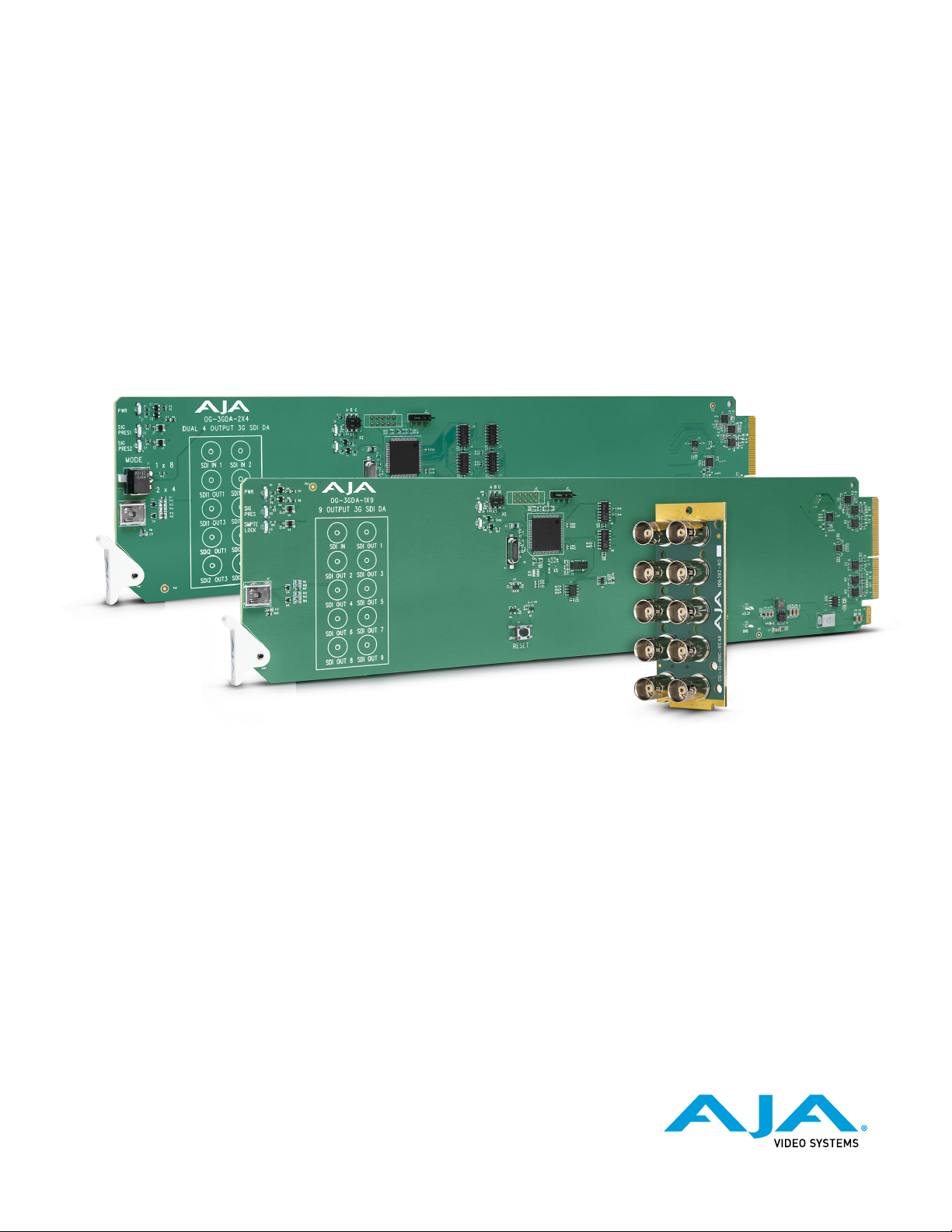
AJA’s OG-3GDA Series cards are state-of-the-art, openGear-compatible, 3G-SDI
distribution amplifiers.
Features
• openGear compatible card (requires 2 slots, rear card included)
• Use with openGear 2RU frames
• Controlled by DashBoard network control software
• Automatic detection and re-clocking of 270Mb, 1.5Gb, and 3Gb SDI data rates
• Excellent input jitter tolerance and low jitter re-clocked outputs
• Input Present and Input SMPTE Lock LEDs (OG-3GDA-1x9)
• Input Present LEDs (OG-3GDA-2x4)
• Hot-swap capable
• 5 year warranty
OG-3GDA-1x9
For the OG-3GDA-1x9, the incoming SD, HD or 3G signal is distributed to each
of the nine 3G-SDI outputs, allowing the same signal to be sent to multiple
destinations simultaneously.
If the incoming SD, HD or 3G signal is one of the five SMPTE rates (270 Mbps, 1.483
Gbps, 1.485 Gbps, 2.966 Gbps, 2.970 Gbps), the signal will be reclocked, and both
the SMPTE Lock LED and Signal Present LED will illuminate. Otherwise, if a nonSMPTE input is detected, the signal will bypass the reclocker and only the Signal
Present LED will illuminate.
OG-3GDA Series openGear Cards v1.2 4 www.aja.com

OG-3GDA-2x4
The OG-3GDA-2x4 offers two modes: Dual 1x4 or Single 1x8. In either mode, the
OG-3GDA-2x4 allows the same signal or signals to be sent to multiple destinations
simultaneously.
The incoming SD, HD or 3G signal(s) will be reclocked if it is one of the five SMPTE
rates (270 Mbps, 1.483 Gbps, 1.485 Gbps, 2.966 Gbps, 2.970 Gbps). Otherwise the
signal(s) will bypass the reclocker and be present at the outputs.
When a SD, HD, or 3G signal is detected, regardless of its compliance to SMPTE
standards, the Signal Present 1 and/or Signal Present 2 LEDs will illuminate,
depending on where the signal input is detected.
Dual 1x4 Mode
In Dual 1x4 Mode, the incoming SD, HD or 3G signals coming in through SDI Input
1 and SDI Input 2 are distributed to the two corresponding sets of four 3G-SDI
outputs. The two DAs are completely independent.
Single 1x8 Mode
In Single 1x8 Mode, the SD, HD or 3G signal coming in through SDI Input 1 is
distributed to the eight 3G-SDI outputs. Both Signal Present LEDs will illuminate
when a signal is present on SDI in 1.
LED Indicators
For OG-3GDA-1x9
LEDs on the front (near door) of each card indicate, from top to bottom:
• DC power detected (green)
• Input signal present (green)
• Input reclocker locked (green)
For OG-3GDA-2x4
LEDs on the front (near door) of each card indicate, from top to bottom:
• DC power detected (green)
• Input 1 signal present (green)
• Input 2 signal present (green)
OG-3GDA Series openGear Cards v1.2 5 www.aja.com
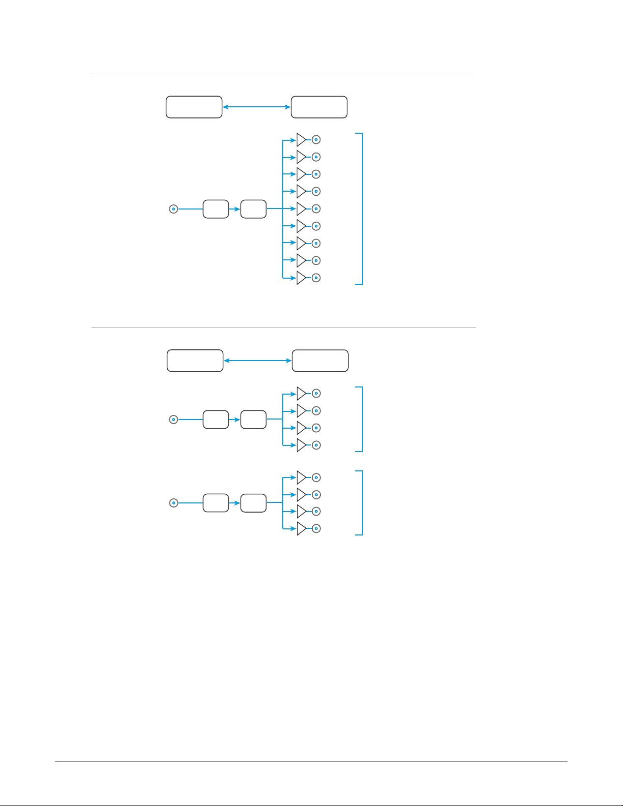
Block Diagram for OG-3GDA-1x9
Figure 1. OG-3GDA-1x9 Converter, Simplified Block Diagram
DashBoard
3G-SDI with
Embedded Audio In
Cable
EQ
ReClock
Control
SDI Out 1
SDI Out 2
SDI Out 3
SDI Out 4
SDI Out 5
SDI Out 6
SDI Out 7
SDI Out 8
SDI Out 9
3G-SDI with
Embedded Audio Out
Outputs pass
embedded audio
and metadata
Block Diagram for OG-3GDA-2x4 in Dual 1x4 Mode
Figure 2. OG-3GDA-2x4 Converter in Dual 1x4 Mode, Simplified Block Diagram
DashBoard
3G-SDI with
Embedded Audio In
SDI Input 1
Cable
EQ
ReClock
Control
SDI 1 Out 1
SDI 1 Out 2
SDI 1 Out 3
SDI 1 Out 4
3G-SDI with
Embedded Audio Out
Outputs pass
embedded audio
and metadata
3G-SDI with
Embedded Audio In
SDI Input 2
Cable
EQ
ReClock
SDI 2 Out 1
SDI 2 Out 2
SDI 2 Out 3
SDI 2 Out 4
3G-SDI with
Embedded Audio Out
Outputs pass
embedded audio
and metadata
OG-3GDA Series openGear Cards v1.2 6 www.aja.com
Block Diagram for OG-3GDA-2x4 in Single 1x8 Mode
Figure 3. OG-3GDA-2x4 Converter in 1x8 Mode, Simplified Block Diagram
DashBoard
3G-SDI with
Embedded Audio In
SDI Input 1
Cable
EQ
ReClock
Control
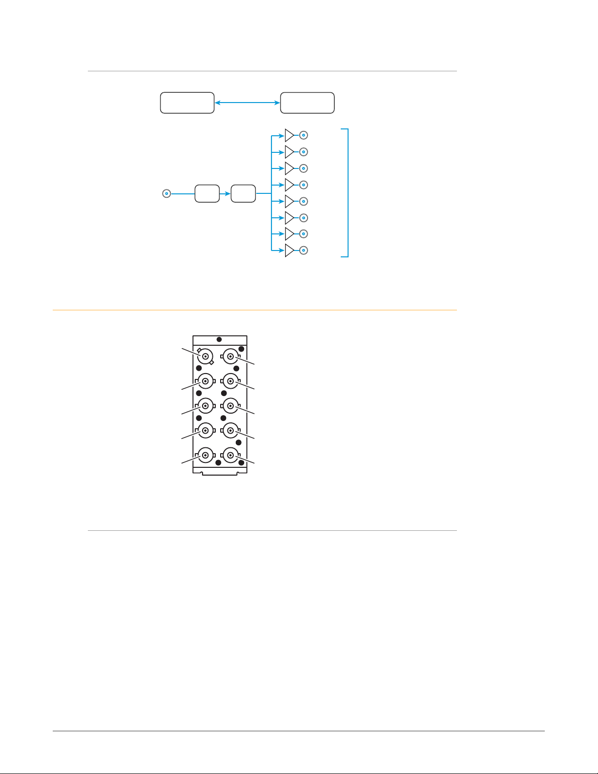
I/O Connections for OG-3GDA-1x9
Figure 4. Rear View of OG-3GDA-1x9 Card Connectors
Input
BNC
Output 1*
BNC
Output 2
BNC
Output 4*
BNC
Output 6
BNC
Output 8
BNC
Output 3*
BNC
Output 5
BNC
Output 7*
BNC
Output 9*
BNC
SDI 1 Out 1
SDI 1 Out 2
SDI 1 Out 3
SDI 1 Out 4
SDI 1 Out 5
SDI 1 Out 6
SDI 1 Out 7
SDI 1 Out 8
3G-SDI with
Embedded Audio Out
Outputs pass
embedded audio
and metadata
* Non Inverting Outputs
Inverted and Non-Inverted Outputs
Five of the outputs (1, 3, 4, 7, 9) are non-inverting. These are suitable for levelsensitive signaling, such as DVB-ASI. The other four outputs (2, 5, 6, 8) are
identical, except inverted. All outputs are fully SDI compatible.
OG-3GDA Series openGear Cards v1.2 7 www.aja.com
I/O Connections for OG-3GDA-2x4, Dual 1x4 Mode
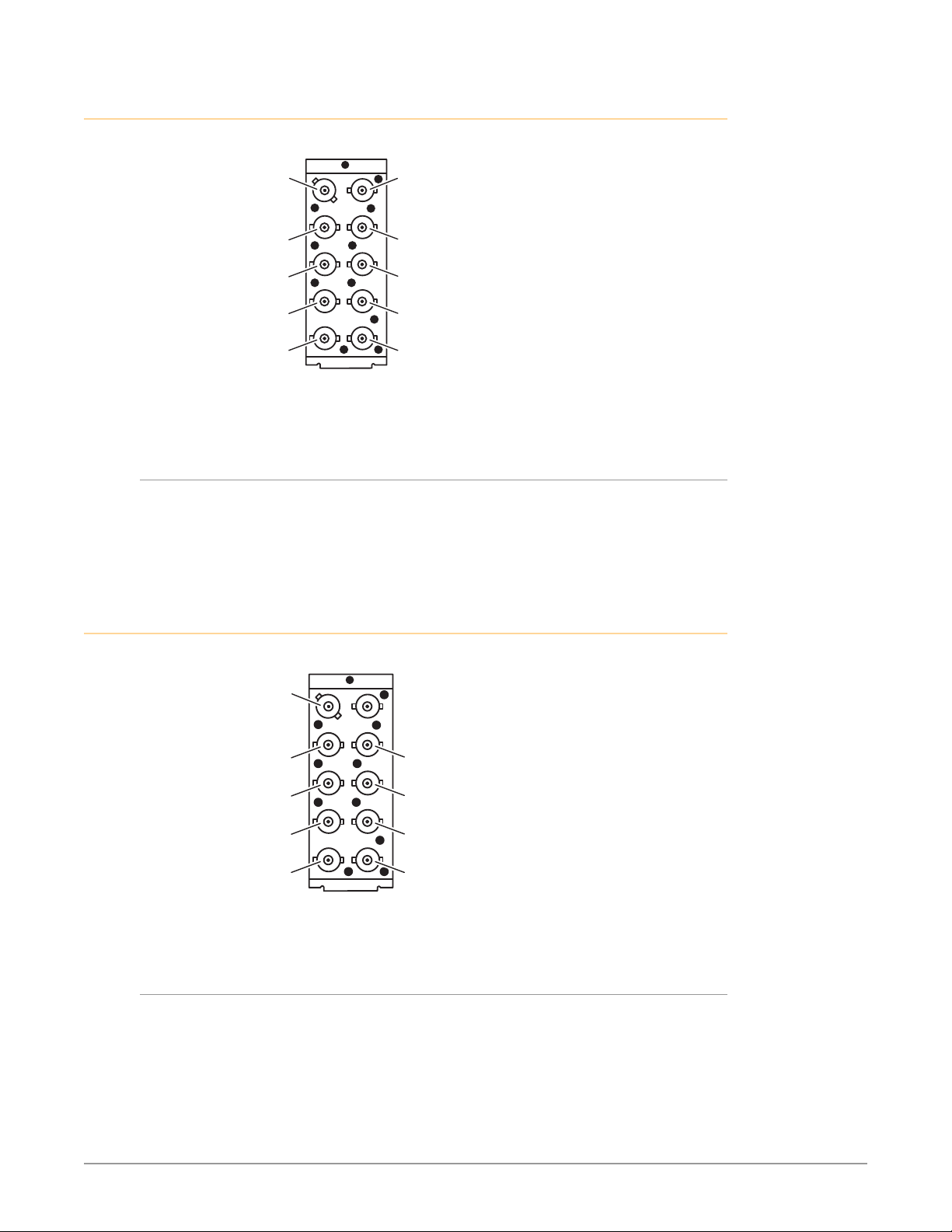
Figure 5. Rear View of OG-3GDA-2x4 Card Connectors, Dual 1x4 Mode
SDI Input 1
BNC (J1)
SDI Input 2
BNC (J2)
SDI 1 Out 1
BNC (J3)
SDI 1 Out 3*
BNC (J5)
SDI 2 Out 1
BNC (J7)
SDI 2 Out 3
BNC (J9)
* Non Inverting Outputs
SDI 1 Out 2*
BNC (J4)
SDI 1 Out 4
BNC (J6)
SDI 2 Out 2*
BNC (J8)
SDI 2 Out 4*
BNC (J10)
Inverted and Non-Inverted Outputs
In Dual 1x4 Mode, four of the outputs (SDI 1 Out 2, SDI 1 Out 3, SDI 2 Out 2, SDI 2
Out 4) are non-inverting. These are suitable for level-sensitive signaling, such as
DVB-ASI. The other four outputs (SDI 1 Out 1, SDI 1 Out 4, SDI 2 Out 1, SDI 2 Out 3)
are identical, except inverted. All outputs are fully SDI compatible.
I/O Connections for OG-3GDA-2x4, Single 1x8 Mode
Figure 6. Rear View of OG-3GDA-2x4 Card Connectors, 1x8 Mode
SDI Input 1
BNC (J1)
SDI Out 1
BNC (J3)
SDI Out 3*
BNC (J5)
SDI Out 5
BNC (J7)
SDI Out 7
BNC (J9)
* Non Inverting Outputs
SDI Out 2*
BNC (J4)
SDI Out 4
BNC (J6)
SDI Out 6*
BNC (J8)
SDI Out 8*
BNC (J10)
Inverted and Non-Inverted Outputs
In 1x8 Mode, four of the outputs (SDI Out 2, SDI Out 3, SDI Out 6, SDI Out 8) are
non-inverting. These are suitable for level-sensitive signaling, such as DVB-ASI.
The other four outputs (1, 4, 5, 7) are identical, except inverted. All outputs are
fully SDI compatible.
OG-3GDA Series openGear Cards v1.2 8 www.aja.com
Signal Indicators in the DashBoard Control System
Card Alarm State – Red
This potential card state will result in a red alarm indicator:
• HW Status Unsupported Rear Module
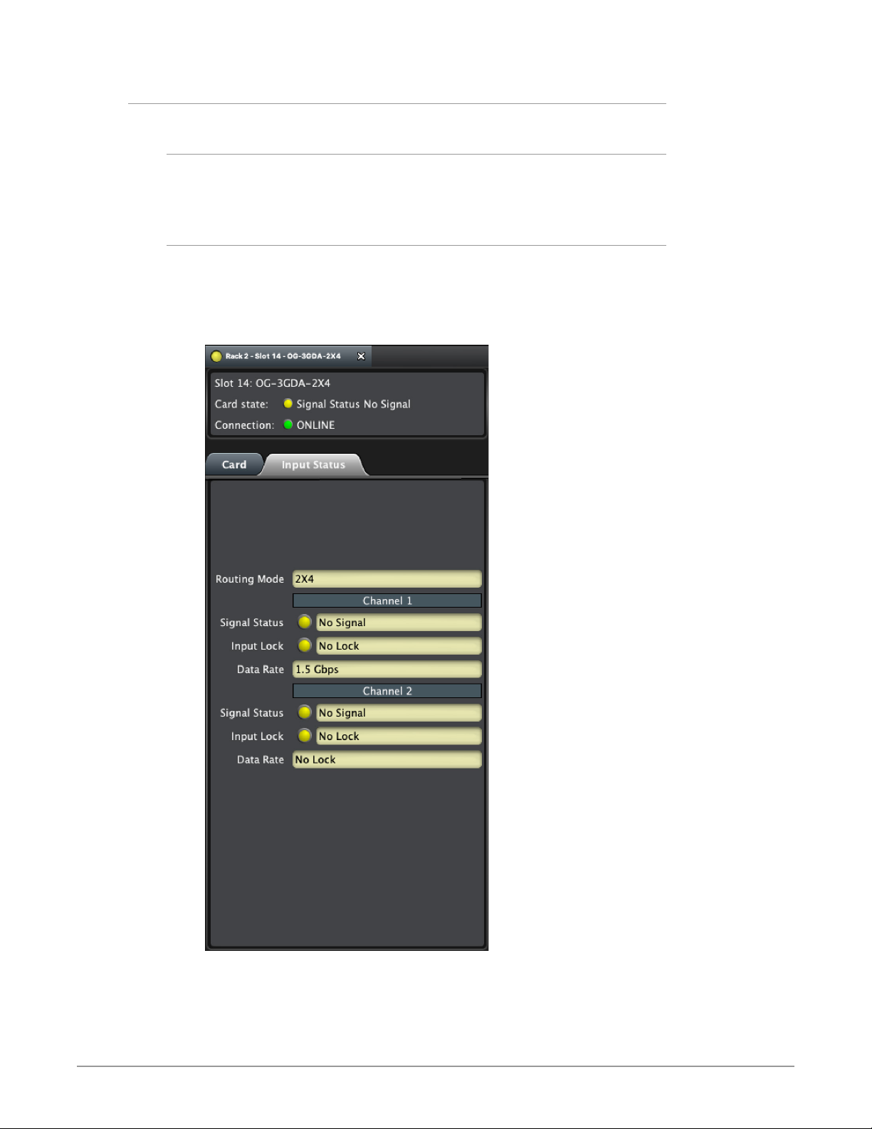
Card Alarm State – Yellow
When the signal is either not present or is not locked, the DashBoard Control
System shows a yellow Card State alarm: "Signal Status No Signal." Additionally,
under the Input Status tab, the Signal Status is shown as "No Signal," and the
Input Lock is shown as "No Lock."
Figure 7. Signal not present or not locked
OG-3GDA Series openGear Cards v1.2 9 www.aja.com
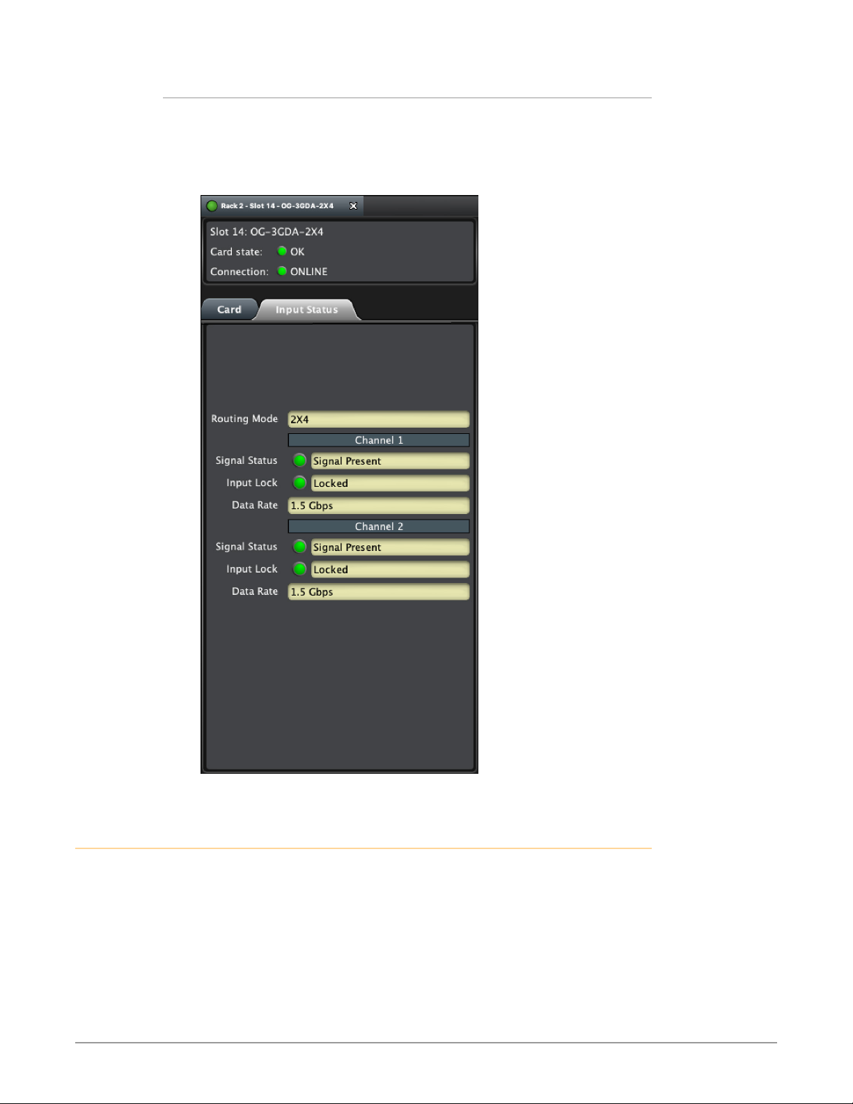
Card Alarm State – Green
When there is a valid input signal detected, the DashBoard Control System shows
a green Card State. Additionally, under the Input Status tab, the Signal Status is
shown as "Signal Present," and the Input Lock is shown as "Locked." The detected
Data Rate of the SDI Signal is also indicated (for example, "1.5 Gbps").
Figure 8. Signal is present and locked
User Controls
The OG-3GDA Series cards can be used right out of the box for many applications,
since they are designed to recognize inputs and perform standard actions
automatically. However, you can also remotely monitor the OG-3GDA Series
through the DashBoard Control System for an openGear Frame.
OG-3GDA Series openGear Cards v1.2 10 www.aja.com
DashBoard Control System
The DashBoard Control System, created by Ross Video, provides a control
interface between Windows, macOS and Linux computers and the cards installed
in an openGear frame. DashBoard operates through TCP/IP communication
and requires an Ethernet connection between the controlling computer and an
openGear frame.
For details about acquiring and using the DashBoard Control System, refer to
"Using the DashBoard Control System" on page 15.
openGear and AJA
openGear is an open-architecture, modular frame system designed by Ross
Video and supported by a diverse range of terminal equipment manufacturers,
including AJA. Ross Video manufactures the frames, power supplies and network
cards for openGear. AJA is a reseller of the openGear frames.
AJA Video is a leading manufacturer of video interface technologies, converters,
digital video recording solutions and professional cameras, bringing highquality, cost-effective products to the professional, broadcast and postproduction markets. AJA products, including openGear cards, are designed and
manufactured at our facilities in Grass Valley, California.
Installation
Summary
Unpacking
Installing an OG-3GDA Series card into an OG-X-FR openGear frame consists of
the following steps:
• Install the Rear Panel onto the back of the frame corresponding to the slot pair
you will be using for the OG-3GDA Series card.
• Insert the OG-3GDA Series card into the frame in the right (even numbered)
slot of the pair.
• Connect the BNC cabling to the Rear Panel.
ESD Susceptibility - Static discharge can cause serious damage to sensitive
semiconductor devices. Avoid handling circuit boards in high static
environments such as carpeted areas, and when wearing synthetic fiber
clothing. Always exercise proper grounding precautions when working on circuit
boards and related equipment.
Unpack each openGear product you received from the shipping container and
ensure that all items are included. If any items are missing or damaged, contact
your sales representative or AJA directly.
Parts List
Quantity Description
1 OG-3GDA Series Front Card in ESD bag
1 10 BNC Rear Card
OG-3GDA Series openGear Cards v1.2 11 www.aja.com
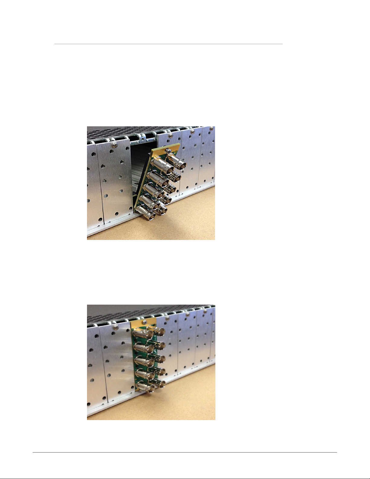
Rear OG-3GDA Series Card Installation
1. Ensure that the frame is properly installed.
2. Locate the card frame slot on the rear of the openGear frame into which you
wish to install the openGear card.
NOTE: An OG-3GDA Series card occupies two slots in the frame.
3. Using a Phillips screwdriver, unscrew the top screw from the desired blank
rear plate and remove the rear plate.
4. Seat the bottom of the Rear Card in the seating slot at the base of the frame
back plane.
Figure 9. Rear Card Inserting Into Frame Seating Slot
5. Align the top screw of the Rear Card with the screw hole on the top edge of
the frame back plane.
6. Ensure the Rear Card aligns with the desired card slot before tightening the
screw.
7. Using a Phillips screwdriver, fasten the Rear Card to the frame back plane.
Do not over tighten.
Figure 10. Rear Card Inserted Into Frame Seating Slot
8. Ensure proper frame cooling and ventilation by having all rear frame slots
covered with rear modules or blank metal plates if plates are not preinstalled.
OG-3GDA Series openGear Cards v1.2 12 www.aja.com
 Loading...