

Page 1
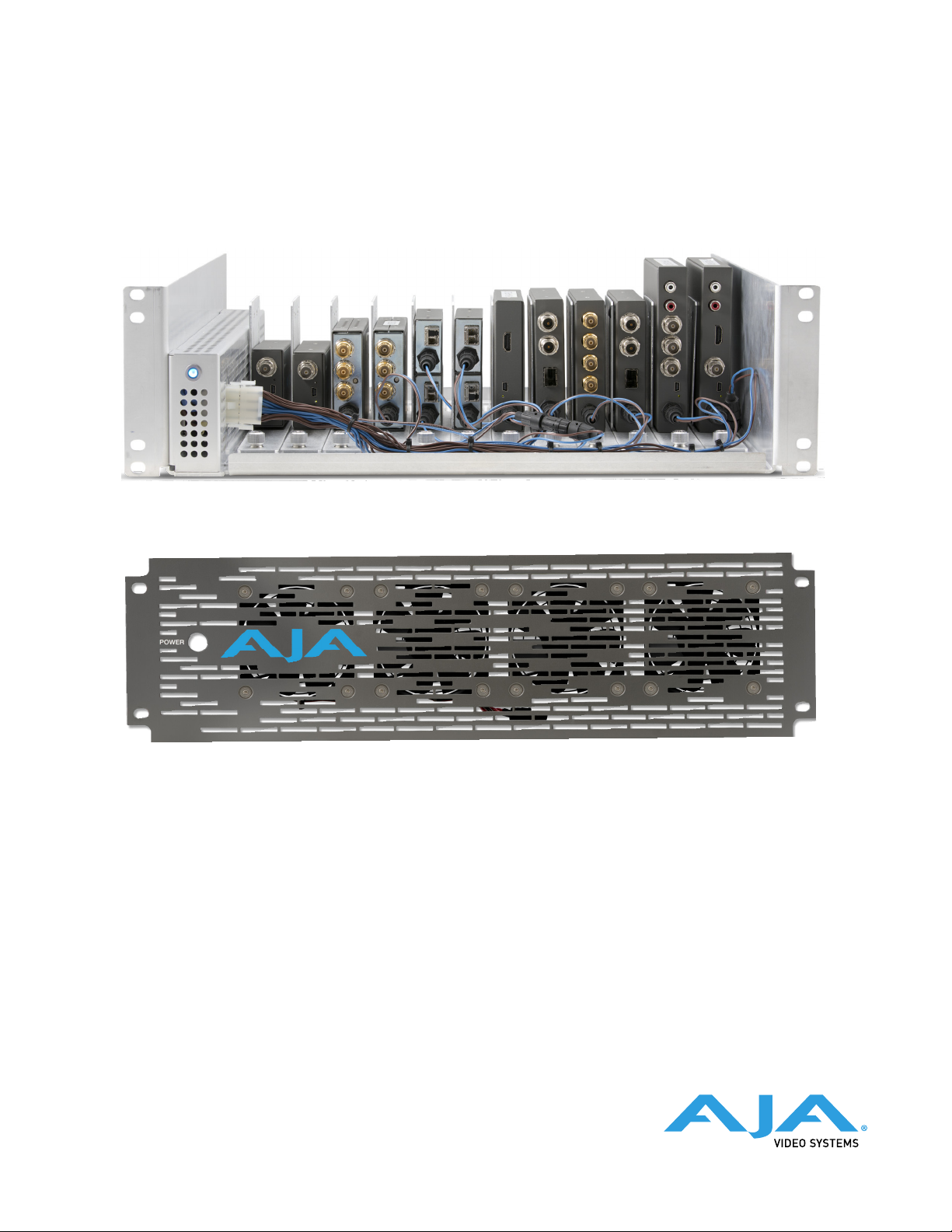
DRM2
Mini-Converter Rack-Mount Frame
(Mini-Converters Sold Separately)
Installation and Operation Guide
Version 1.0
Published November 9, 2023
(Optional Active Faceplate)
Page 2

Notices
Trademarks
Copyright
AJA® and Because it matters.® are registered trademarks of AJA Video Systems, Inc.
for use with most AJA products. AJA™ is a trademark of AJA Video Systems, Inc. for
use with recorder, router, software and camera products. Because it matters.™ is a
trademark of AJA Video Systems, Inc. for use with camera products.
Corvid Ultra®, lo®, Ki Pro®, KONA®, KUMO®, ROI® and T-Tap® are registered trademarks of
AJA Video Systems, Inc.
AJA Control Room™, KiStor™, Science of the Beautiful™, TruScale™, V2Analog™ and
V2Digital™ are trademarks of AJA Video Systems, Inc.
All other trademarks are the property of their respective owners.
Copyright © 2023 AJA Video Systems, Inc. All rights reserved. All information in
this manual is subject to change without notice. No part of the document may be
reproduced or transmitted in any form, or by any means, electronic or mechanical,
including photocopying or recording, without the express written permission of AJA
Video Systems, Inc.
Contacting AJA Technical Support or Sales
Please have all pertinent information at hand prior to contacting AJA support or sales.
Support Telephone: +1.530.271.3190
Support Website: https://www.aja.com/support/contact
Support Email: [email protected]
Sales Email: [email protected]
Shipping Address: AJA Video Systems
180 Litton Drive
Grass Valley, CA 95945, USA
DRM2 Mini-Converter Rack-Mount Frame Manual v1.0 2 www.aja.com
Page 3

Contents
Notices . . . . . . . . . . . . . . . . . . . . . . . . . . . . . . . . . . . . . .2
Trademarks . . . . . . . . . . . . . . . . . . . . . . . . . . . . . . . . . . . . . . . . . . . 2
Copyright . . . . . . . . . . . . . . . . . . . . . . . . . . . . . . . . . . . . . . . . . . . . 2
Contacting AJA Technical Support or Sales . . . . . . . . . . . . . . . . . . . . . . . 2
Chapter 1 – Introduction . . . . . . . . . . . . . . . . . . . . . . . . . . . 4
Overview. . . . . . . . . . . . . . . . . . . . . . . . . . . . . . . . . . . . . . . . . . . . . 4
Mini-Converter Frame for 19-inch Racks . . . . . . . . . . . . . . . . . . . . . . . 4
High Capacity . . . . . . . . . . . . . . . . . . . . . . . . . . . . . . . . . . . . . . . . 4
Features . . . . . . . . . . . . . . . . . . . . . . . . . . . . . . . . . . . . . . . . . . . 5
Front Faceplate . . . . . . . . . . . . . . . . . . . . . . . . . . . . . . . . . . . . . . . . .5
Chapter 2 – Installation . . . . . . . . . . . . . . . . . . . . . . . . . . . . 7
Included in the Box . . . . . . . . . . . . . . . . . . . . . . . . . . . . . . . . . . . . . . 7
Basic Order . . . . . . . . . . . . . . . . . . . . . . . . . . . . . . . . . . . . . . . . . . 7
Parts Available Separately . . . . . . . . . . . . . . . . . . . . . . . . . . . . . . . . 7
Overview of Installation . . . . . . . . . . . . . . . . . . . . . . . . . . . . . . . . . . . 8
Rack Mount Frame with Carrier Slots . . . . . . . . . . . . . . . . . . . . . . . . . 8
Mini-Converter Carriers . . . . . . . . . . . . . . . . . . . . . . . . . . . . . . . . . . 8
Twelve Mini-Converters Example Conguration . . . . . . . . . . . . . . . . . . 9
Installation. . . . . . . . . . . . . . . . . . . . . . . . . . . . . . . . . . . . . . . . . . . .9
Mounting Converters onto Carriers . . . . . . . . . . . . . . . . . . . . . . . . . . 9
Installing Converters into DRM2 Frame . . . . . . . . . . . . . . . . . . . . . . . 11
Attach Passive Faceplate . . . . . . . . . . . . . . . . . . . . . . . . . . . . . . . . 12
Attach Active Faceplate . . . . . . . . . . . . . . . . . . . . . . . . . . . . . . . . . 13
Uninstallation . . . . . . . . . . . . . . . . . . . . . . . . . . . . . . . . . . . . . . . . . 14
Remove Passive Faceplate . . . . . . . . . . . . . . . . . . . . . . . . . . . . . . . 14
Remove Active Faceplate . . . . . . . . . . . . . . . . . . . . . . . . . . . . . . . 14
Remove Carrier from DRM2 Frame. . . . . . . . . . . . . . . . . . . . . . . . . . 15
Remove Rear-Mounted Converter from Carrier. . . . . . . . . . . . . . . . . . 15
Remove Bottom-Mounted Converter from Carrier. . . . . . . . . . . . . . . . 16
Special Case Installations . . . . . . . . . . . . . . . . . . . . . . . . . . . . . . . . . 16
Mounting Converters with DIP Switches . . . . . . . . . . . . . . . . . . . . . . 16
Stacking FiDO Converters Two-High. . . . . . . . . . . . . . . . . . . . . . . . . 16
USB Connections. . . . . . . . . . . . . . . . . . . . . . . . . . . . . . . . . . . . . . . 19
USB Hub . . . . . . . . . . . . . . . . . . . . . . . . . . . . . . . . . . . . . . . . . . 19
AJA Mini-Cong USB Device Select . . . . . . . . . . . . . . . . . . . . . . . . . 19
Appendix A – Specications . . . . . . . . . . . . . . . . . . . . . . . . 20
DRM2 Tech Specs . . . . . . . . . . . . . . . . . . . . . . . . . . . . . . . . . . . . . . 20
Appendix B – Safety and Compliance . . . . . . . . . . . . . . . . . .21
Warranty and Liability Information . . . . . . . . . . . . . . . . . . . .29
Index. . . . . . . . . . . . . . . . . . . . . . . . . . . . . . . . . . . . . . .30
DRM2 Mini-Converter Rack-Mount Frame Manual v1.0 3 www.aja.com
Page 4
Chapter 1 – Introduction
Overview
Mini-Converter Frame for 19-inch Racks
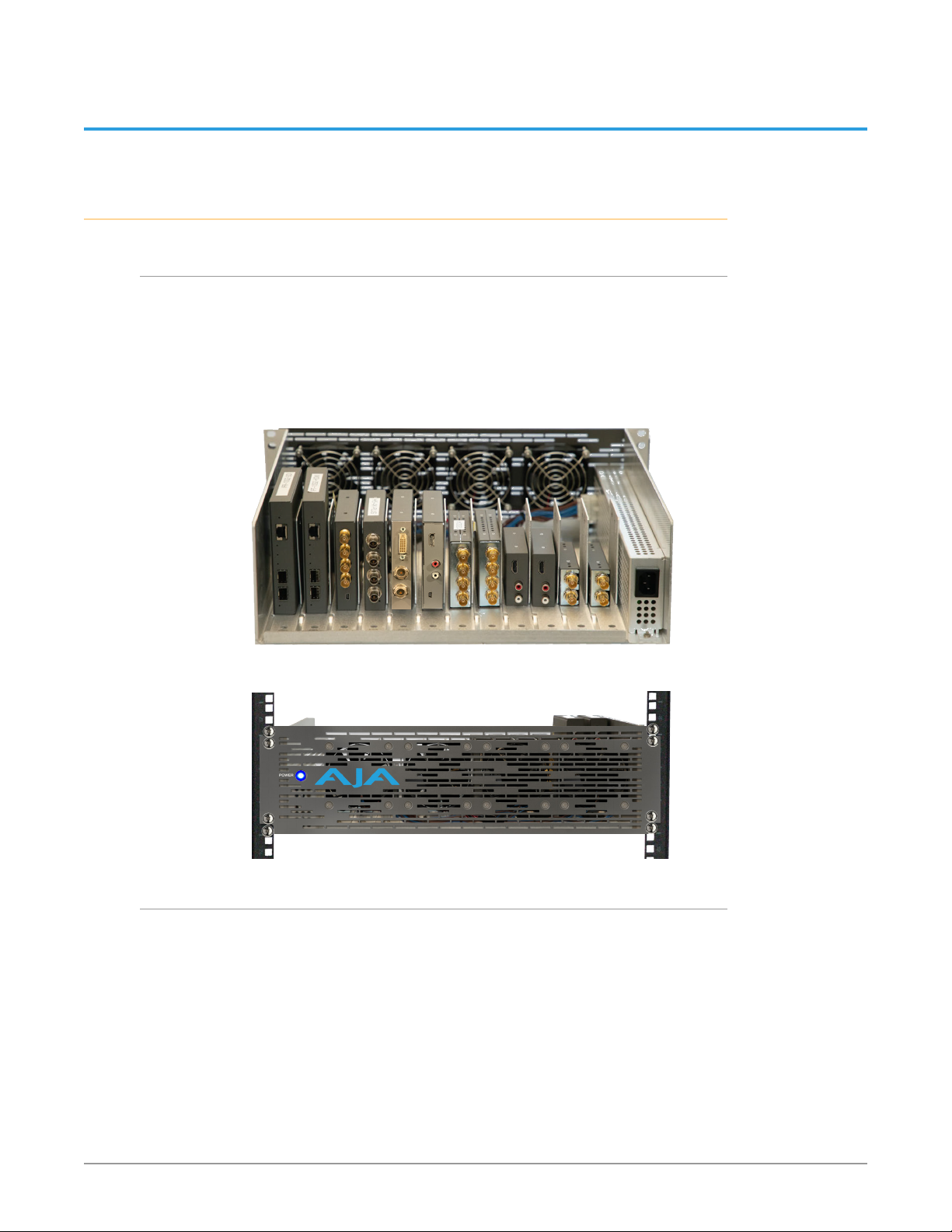
DRM2 is a 3RU rack mount frame engineered to professionally mount and power
up to twelve (12) AJA Mini-Converters of any current size and form-factor. The
DRM2 delivers total power of up to 200 Watts.
The frame includes a 110/220VAC (12-Amp) power supply. Twelve +5V power leads
are provided via a DC Wiring Harness from the main power supply to power the
converters.
Figure 1. DRM2 with twelve Mini-Converters mounted on Carriers
Figure 2. 19" rack-mounted DRM2 shown with (optional) Active Faceplate
High Capacity
Here are some examples of what is possible with the DRM2 using only 3RU of rack
space:
• 12 independent channels of 4K HDMI to 12G-SDI or 12G-SDI to 4K HDMI
conversion
• 12 independent scan-conversion channels
• 12 independent Up/Down/Cross conversion channels
• Up to 60 channels of HD or SD sync distribution utilizing two GEN10s and ten
3GDAs or C10DAs
• 48 channels of 3G or 12G SDI to Fiber or Fiber to SDI conversion
DRM2 Mini-Converter Rack-Mount Frame Manual v1.0 4 www.aja.com
Page 5
Features
• 3RU form-factor allows all AJA Mini-Converters to fit cleanly in the chassis.
• Flexible 12-slot frame design.
• Modular “Carrier” based Mini-Converter mounts are rugged, simple to use,
and easy to access from the front or rear of the chassis. Twelve Carriers are
included with the DRM2 frame, one for each slot. Additional/replacement
Carriers are available.
• The powered Active Faceplate offers four fans for maximum cooling in higher
ambient temperature installations.
• DRM2 200W Power Supply supports any combination of up to 12 AJA MiniConverters.
• DRM2 also supports up to 24 AJA FiDO and FiDO-2(T/R/TR) Mini-Converters
by using optional DC power Y-Cables, and mounting pairs of FiDOs on single
Carriers.
• Main DC Power Harness included has thirteen D5/10-PC power connectors.
Twelve of the D5/10-PC power connectors are to be utilized by the MiniConverters, and one is reserved for the (optional) Active Faceplate.
• Modular Power Supply Connector also allows users the option to create
custom cabling (within power specifications). For example, cables with more
D5/10-PC connectors could be made for higher density installations, upon
engineering review.
Front Faceplate
Two types of front faceplates are available for the DRM2 frame:
a Passive Faceplate and an Active Faceplate.
Passive Faceplate
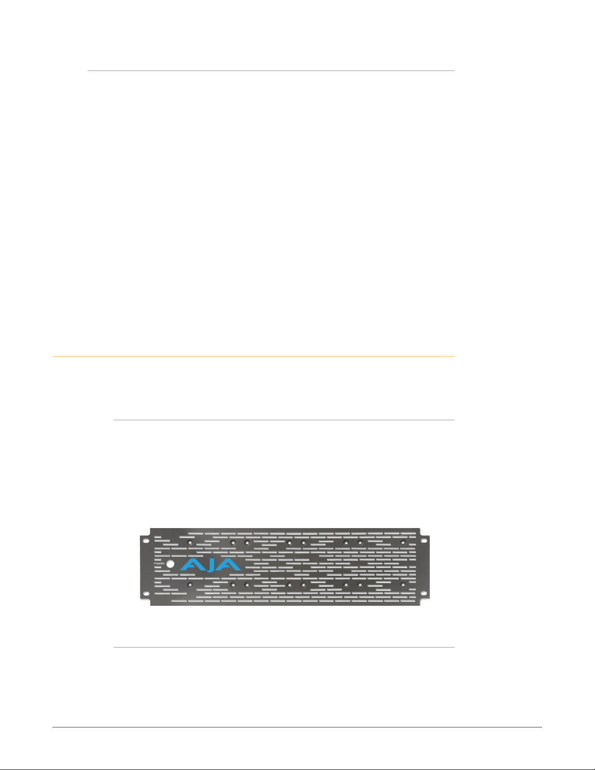
The DRM2 ships with a standard Passive Faceplate with ventilation holes. For
users that want to upgrade their passive faceplate to the active version, the Active
Faceplate is also available as a standalone part. See "Parts Available Separately" on
page 7.
The Passive Faceplate is sufficient for rack installations which provide their own
cooling, or for when lower wattage Mini-Converters are installed and lower
ambient temperatures are present.
Figure 3. Passive Faceplate
Active Faceplate
The Active Faceplate enables the DRM2 frame to be used with higher wattage
consuming Mini-Converters, and/or to be used in higher ambient temperature
environments.
The DRM2-AP product configuration ships the Mini-Converter rack frame
together with an Active Faceplate having four cooling fans.
DRM2 Mini-Converter Rack-Mount Frame Manual v1.0 5 www.aja.com
Page 6
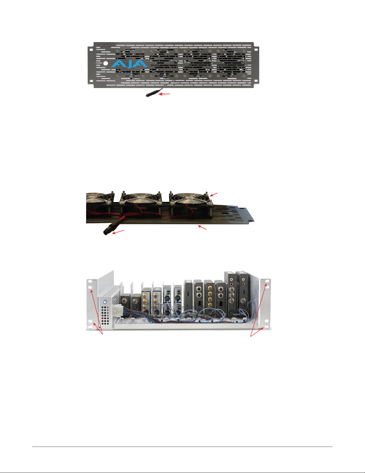
Figure 4. Active Faceplate
DC Power Connector for fans
The Active Faceplate allows for a high-density installation of AJA’s most powerful
Mini-Converters, without concern for heat soak. The Active Faceplate connects to
the DRM2 +5V DC power supply using any available DC power connector found
on the DRM2's DC Power Harness, although one is provided near the middle of
the harness for this use.
If the ambient temperature is under 30C, an Active Faceplate is recommended if
power consumption exceeds 100W. If the ambient temperature is over 30C, then
an Active Faceplate is recommended if power consumption exceeds 75W. Please
consult the Tech Specs of your Mini-Converters to calculate expected power
consumption.
Figure 5. Active Faceplate Fans and Power Connector
Active Cooling
Fans ( 4 total)
DC Power Connector for fans
Active Faceplate
Both DRM2 faceplate types have four "inner" mounting holes for the faceplate, in
addition to the four "outer" 19" rack-mounting holes for the DRM2 frame.
Figure 6. Separate faceplate and rack mount screw holes
Faceplate Mount
“Inner” Screw Holes (4)
“Outer” Screw Holes (4)
Rack Mount
Both sets of holes may use the same size 19" rack screws.
NOTE: 19" rack rails vary in design, so use the fasteners which your rack provides.
This design allows removal and replacement of the faceplate without removing
the DRM2 from the rack. This allows easy access to Mini-Converters and their
cabling from the front. The above example shows all Mini-Converters connected
to the DC Power Harness.
DRM2 Mini-Converter Rack-Mount Frame Manual v1.0 6 www.aja.com
Page 7

Chapter 2 – Installation
Included in the Box
Basic Order
Table 1. Shipping Contents for DRM2 or DRM2-AP Basic Order
Item Quantity Notes
DRM2 Rack Mount Frame 1 19" rack mount frame for AJA mini-converters
Passive or Active Faceplate 1
Carrier 12 Carriers include captive No-Tools secure screws
Anti-vibration screw 12
Mini-Converter rear
mounting screw
Mini-Converter bottom
mounting screw
12
12
Passive Faceplate (with DRM2 order)
- or Active Faceplate (with DRM2-AP order)
10-32 x 0.187 Phillips Pan Head
Secures rear of Carrier for anti-vibration use
4-40 x 0.312 Phillips Flat Head
Secures rear of Mini-Converter to Carrier
2-56 x 0.250 Phillips Flat Head
Secures bottom of Mini-Converter to Carrier
Parts Available Separately
Table 2. Separately Orderable Parts
AJA Part Number Item Quantity Notes
DRM2-AFP
(Active Faceplate)
DRM2-CH12-R0
(Carrier Twelve Pack)
DRM2-CH-R0
(Carrier Single Pack)
DRM2-YC-R0
(Power Cable
Adapter)
DRM2-YC12-R0
(Expansion Kit
Upgrade Kit )
Active Faceplate 1 Faceplate includes four installed fans
Carrier 12 Include captive No-Tools secure screws
Rear-mounting screw 24 4-40 x 0.312 Phillips Flat Head
Bottom-mounting
screw
Carrier 1 Includes captive No-Tools secure screw
Rear-mounting screw 2 4-40 x 0.312 Phillips Flat Head
Bottom-mounting
screw
DC Power Y-Cable 1
DC Power Y-Cable 12
Rear-mounting screw 24 4-40 x 0.312 Phillips Flat Head
24 2-56 x 0.250 Phillips Flat Head
2 2-56 x 0.250 Phillips Flat Head
Adds a second +5VDC DWP male
connector to any single DWP
connector
Adds 12 more +5VDC DWP male
connectors to the DC Power Harness
DRM2 Mini-Converter Rack-Mount Frame Manual v1.0 7 www.aja.com
Page 8
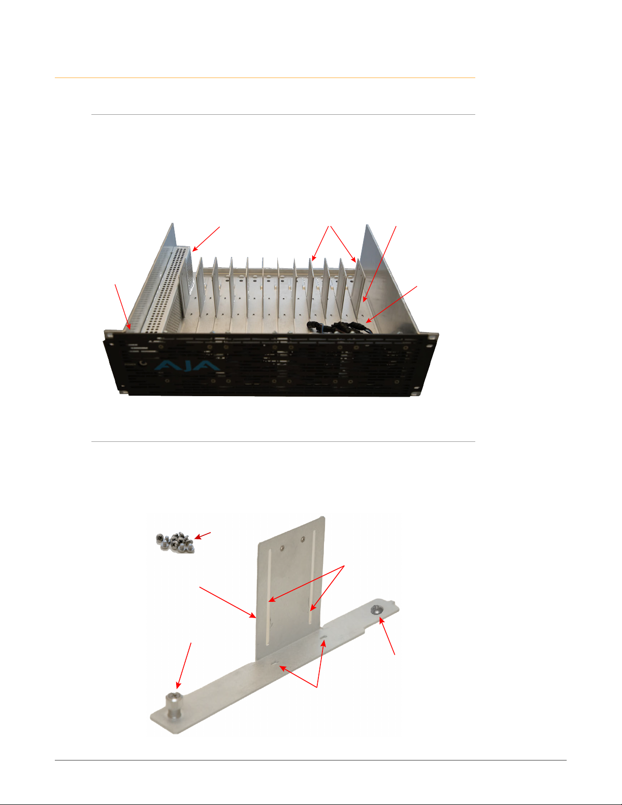
Overview of Installation
Mounting Screws
Carrier
Mounting Bracket
Converter
Rear Mounting
Slots
No-Tools
Secure Screw
Converter
Bottom
Mounting Slots
Rear Screw
(Anti-Vibration
Option)
Rack Mount Frame with Carrier Slots
The DRM2 is a standard 19-inch, 3-RU tall, 15" deep rack mount frame with 12
Carrier Slots, into which Mini-Converter Carrier mounting brackets slide into and
are secured.
Figure 7. DRM2 with empty Carriers in Carrier Slots
Power
Supply
(empty)
Carrier
Mounting
Brackets (12)
Carrier
Mounting
Slots (12)
Active
Cooling
Faceplate
Mini-Converter Carriers
Mini-Converters are not mounted directly into the DRM2 frame. They are first
attached to the Mini-Converter Carrier mounting brackets. The Carriers each
include screws for mounting mini-converters to them, as well as a Carrier Rear
Screw for optional anti-vibration use.
Figure 8. Mini-Converter Carrier mounting bracket and screws
+5V DC
Power
Harness
DRM2 Mini-Converter Rack-Mount Frame Manual v1.0 8 www.aja.com
Page 9
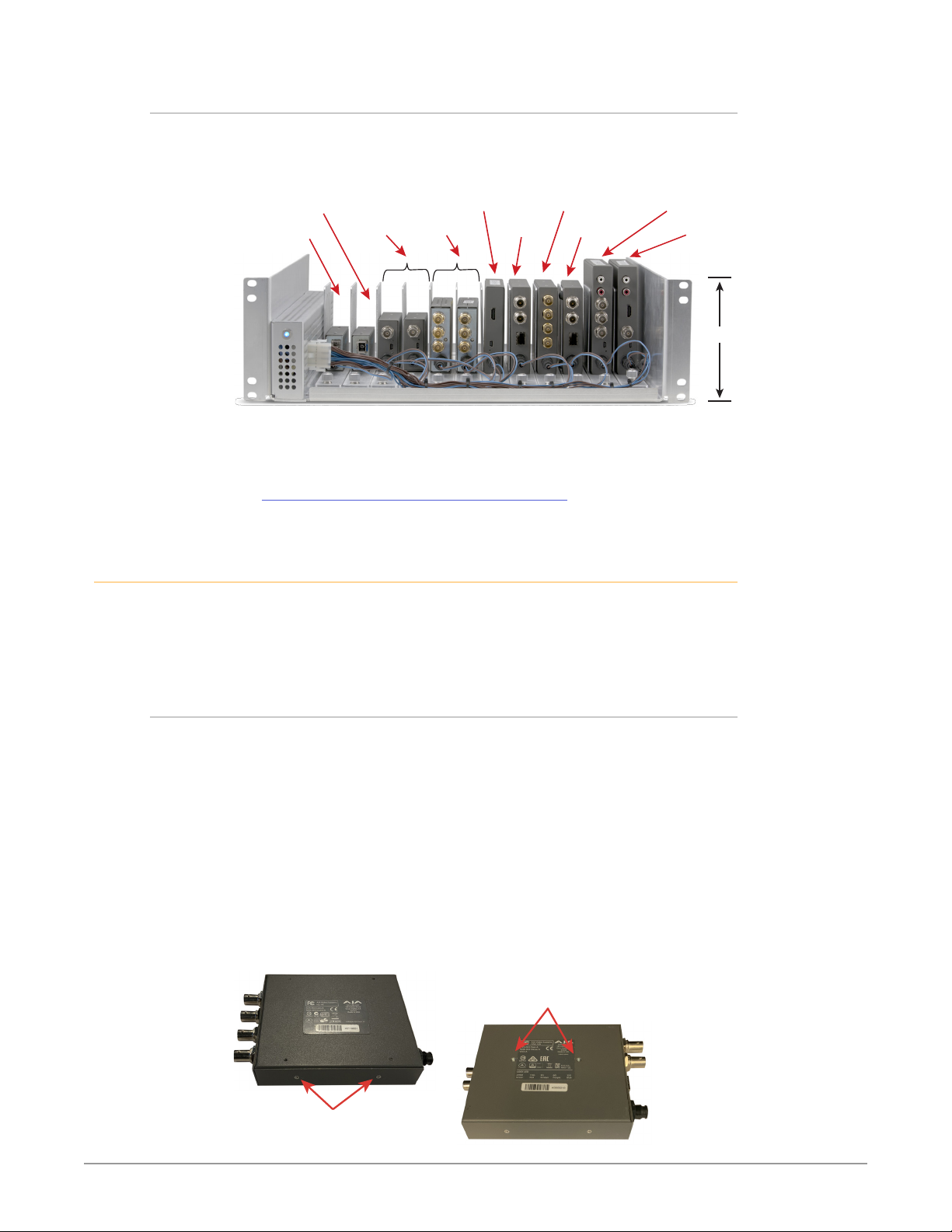
FiDO R-12G-ST
Twelve Mini-Converters Example Configuration
Below find an example of 12 AJA Mini-Converters of various sizes installed into a
single DRM2 frame.
Figure 9. DRM2 with 12 AJA Mini-Converters installed
Installation
FiDO TR-12G
Hi5-Plus (2)
NOTE: The above example is for illustration purposes only, and is not intended to
represent a specific application. Only DC power is shown connected, for clarity.
NOTE: For details on the example AJA mini-converter products shown above, see:
https://www.aja.com/nav/products-mini-converters
DRM Carriers may be shipped pre-installed in the DRM2 frame. If so, first time
converter installation requires removing the Carriers from their Carrier Slots inside
the frame, in order to subsequently mount converters onto them. See "Remove
Carrier from DRM2 Frame" on page 15; then continue on below.
ROI-DVI
12GDA (2)
HA5-12G Hi5-4K-Plus IPR-10G2-HDMI
12GM
IPR-10G2-HDMI
3-RU
Mounting Converters onto Carriers
Which of two alternative methods to use for mounting converters onto Carriers
depends upon the particular model of Mini-Converter. When a particular model
converter has two threaded rear-mounting holes, then the provided rearmounting screws can be used through the carrier mounting slots in the Carrier's
vertical bracket. See "Rear-Mounting Mini-Converters" on page 10.
Other Mini-Converter models which don't have rear-mounting holes, will have to
be attached through the Carrier's bottom plate and into the bottom of the MiniConverter housing. You will reuse the converter's bottom housing screws, or use
those provided. See "Bottom-Mounting Mini-Converters" on page 10.
Use the appropriate method for each Mini-Converter being mounted into the
DRM2. Procedures for both methods are detailed below.
Figure 10. Two methods of attaching Mini-Converters onto Carriers
Mount to Carrier using
rear mounting holes
Mount to Carrier using
bottom housing screws
DRM2 Mini-Converter Rack-Mount Frame Manual v1.0 9 www.aja.com
Page 10
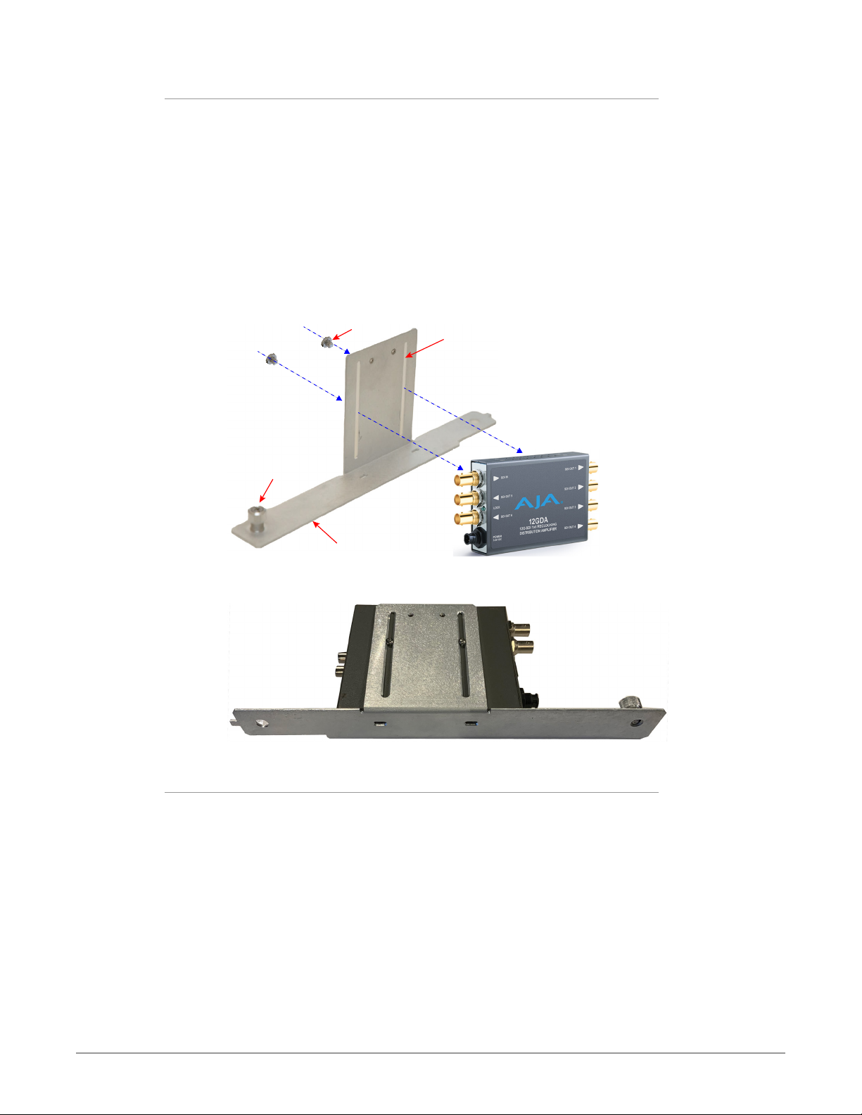
Converter
Rear Mounting Mini-Converters
For each Mini-Converter having rear mounting holes which is to be installed into
the DRM2 frame, follow the below steps:
1. Attach the Mini-Converter to a Carrier bracket using two of the Phillips
mounting screws provided. Adjust the screw positions through the
converter mounting slots in order to align with the mounting holes found in
the back of the particular converter. Do not tighten the screws completely.
2. Slide the converter all the way down against the Carrier bracket bottom
(suggested).
3. Tighten the mounting screws to secure the converter onto the Carrier.
Do not over-tighten.
Figure 11. Rear-mounting a Mini-Converter onto a Carrier bracket
Mounting Screws
Mounting Slots
No-Tools
Secure Screw
Mounting Bracket
Carrier
Figure 12. Example of a Mini-Converter correctly rear -mounted on a Carrier
Bottom Mounting Mini-Converters
For each Mini-Converter which does not have the two rear mounting holes,
attach it instead through the bottom of a Carrier and into the converter housing
as follows:
1. Remove the two small Phillips screws from the bottom edge of the
converter housing, and keep them on hand.
2. Position the Mini-Converter onto the Carrier, orienting its DC power
connection towards the front (nearest the attached No-Tools Secure Screw.)
3. Replace the converter bottom housing screws through the Carrier bottom
mounting slots and into the converter's bottom housing's screw holes.
The nished Mini-Converter/Carrier assembly should look like this:
DRM2 Mini-Converter Rack-Mount Frame Manual v1.0 10 www.aja.com
Page 11
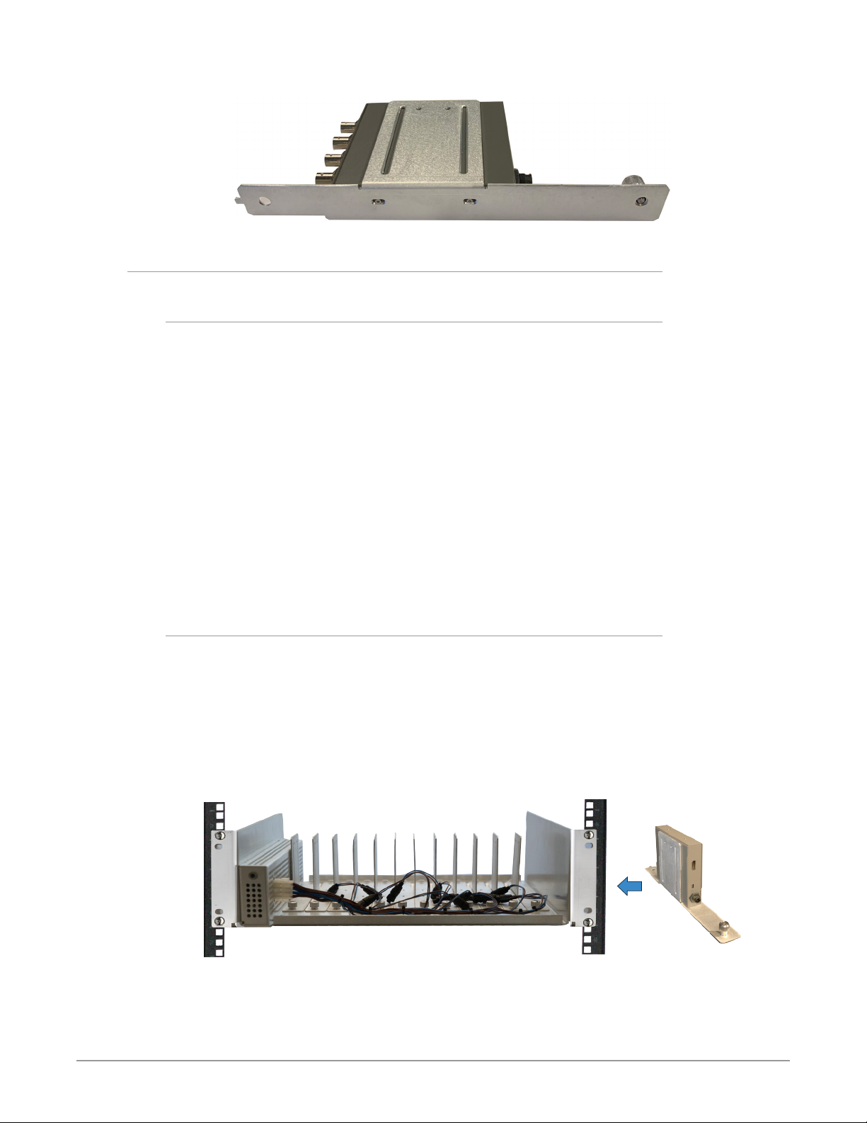
Figure 13. Mini-Converter correctly bottom-mounted on a Carrier
Installing Converters into DRM2 Frame
Overview
After mounting your Mini-Converter(s) onto Carrier bracket(s), you are ready to
install your converter(s) into the DRM2 frame.
If you are installing Converters into a frame having a faceplate previously
attached:
Temporarily remove faceplate - you will remove the DRM2 faceplate and set
it aside. Removing a Passive Faceplate is simple to do, however handling an
Active Faceplate requires careful attention to its power cable.
Continue below when there is no faceplate mounted on the frame:
Install Carriers with converters - you will mount Carriers into their desired
Carrier Slots in the DRM2 frame and secure them. Carriers must have MiniConverters previously mounted on them.
Install faceplate - you will reinstall the faceplate over the DRM2 and into the
rack rails behind it. The Active Faceplate requires attention to its power
connection.
Installing Carriers with Converters into the DRM2 Frame
1. Align and loosely place a Carrier, together with its previously mounted MiniConverter, into an empty Carrier slot in the DRM2 frame. Do not try to align
or tighten the No-Tools Secure Screw yet, that's for a later step; (after rst
making sure the Carrier rear is installed correctly, as described below.)
CAUTION: While placing a Carrier into a slot position in the DRM2 frame, be sure to keep
all DC power (and any other) cables above the Carrier. Avoid letting wires get
caught under a Carrier.
Figure 14. Add Carrier with Mini-Converter into slot in DRM2 Frame
DRM2 Mini-Converter Rack-Mount Frame Manual v1.0 11 www.aja.com
Page 12
Align Carrier
Anti-Vibration
(optional)
Insert Carrier
Align Carrier
Anti-Vibration
(optional)
Insert Carrier
No-Tools Secure Connect Cables
Clear all Wires
Figure 15. Align, insert and secure rear of Carrier
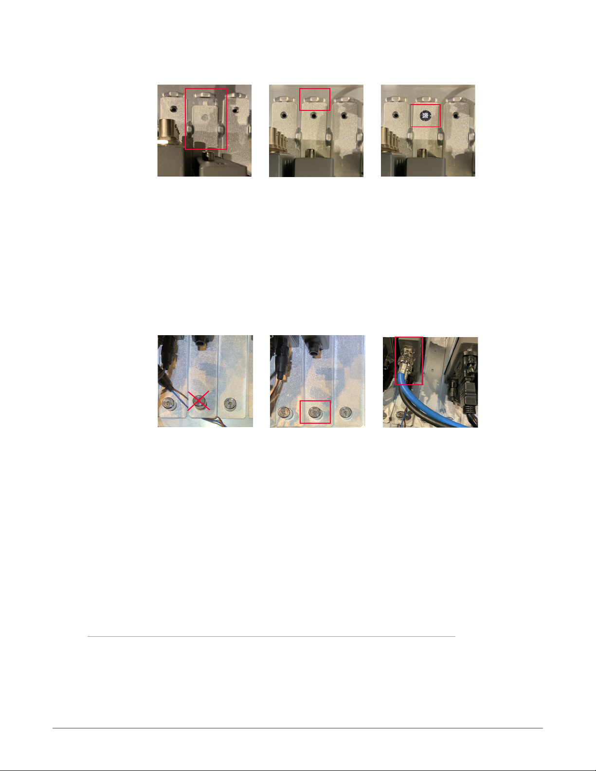
2. Align the rear tab on the Carrier with the small slot on the frame.
3. Slide the Carrier fully back.
4. (Optional) Secure the Carrier at the rear by using a provided Carrier Rear
Screw. Do not over-tighten.
NOTE: Add the anti-vibration Rear Screw to a Carrier when the DRM2 rack is to be used
in a high-vibration environment (including mobile, or otherwise).
CAUTION: Do not over-tighten the Rear Screw.
5. Clear any wires that have been inadvertently caught underneath a Carrier.
Figure 16. Clear wires, secure front of Carrier and connect cables
CAUTION: Do not allow any wires to get inadvertently caught underneath the Carrier.
This could damage the wires or prevent the Carrier from being properly secured.
6. Align and hand-tighten the attached No-Tools Secure Screw at the front of
the Carrier.
7. Attach the Mini-Converter DC power connector to the main DC Power
Harness (or to a Y-Cable if used).
NOTE: The DWP/DWP-U/DWP-U-R1 power supplies which are supplied with all AJA
Mini-Converters can alternatively be used if desired, rather than the supplied
DRM2 frame's main DC Power Harness. Use of separate DC power supplies is
rarely needed however, given the DRM2 200W power supply.
8. Attach data and AV cables to the Mini-Converter as appropriate.
Repeat steps #1 through #8 above for each Mini-Converter Carrier that you wish
to install into the DRM2 frame.
Attach Passive Faceplate
1. Position the Passive Faceplate over its corresponding mounting holes in the
DRM2.
CAUTION: As you position the faceplate, prevent DC power, or any other cables, from
being inadvertently caught between the faceplate and DRM2 frame. Check this
before tightening the rack screws.
DRM2 Mini-Converter Rack-Mount Frame Manual v1.0 12 www.aja.com
Page 13
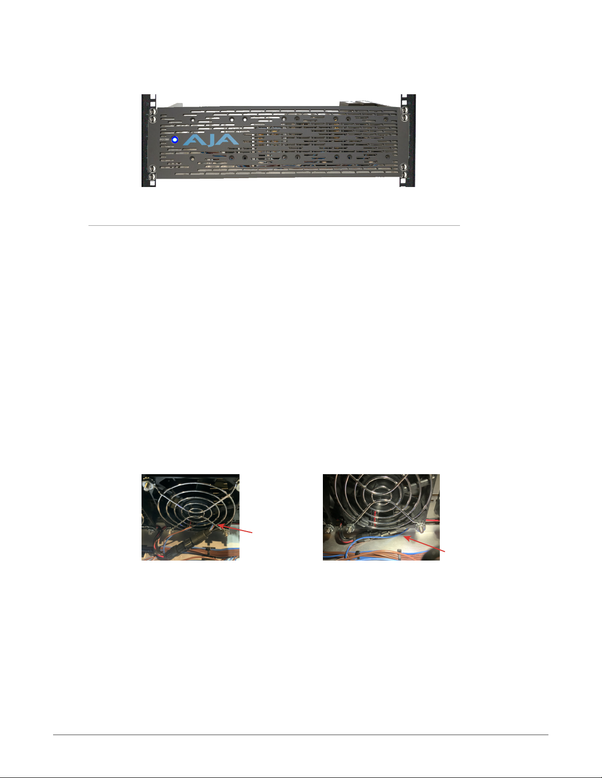
2. Use four rack-mounting screws to secure the faceplate into the rack and
over the DRM2.
Figure 17. Rack-Mounted DRM2 with Passive Faceplate installed
Attach Active Faceplate
1. Position the Active Faceplate horizontally just below the DRM2, fans facing
upwards in order to bring its power cable close to the DRM2 main DC Power
Harness.
2. While supporting the faceplate, connect its DC power connector to any
available connector on the DC Power Harness (or to a Y-Cable if used).
Ideally, use the 13th connector on the DRM2 DC Power Harness because its
middle location in the harness keeps the faceplate cable short.
WARN ING: Do not allow the Active Faceplate to fall, nor to hang by its DC power
connection. This could damage the faceplate DC power connector and/or the
DC Power Harness.
3. While still supporting the faceplate, rotate the faceplate up so that it is in its
vertical mounting orientation.
4. Align the faceplate over the faceplate mounting holes in the DRM2.
WARN ING: While positioning the Active Faceplate and before fully securing it, be
careful to not allow any DC power wires to accidentally push into a fan (i.e.
inside of a fan's safety grill). This could cause a loud fan noise, or cause a
failure of the fan, or cause other electrical damage.
Figure 18. Keep DC power and any other wires from getting inside fan
Do Not
allow wire
inside fan
A suggested good practice for the Active Faceplate power connection is
shown above right: tucked underneath a fan housing at bottom.
5. While still supporting the faceplate, use four rack screws to attach the
faceplate through the DRM2 and into the rack rails.
Good Practice
DRM2 Mini-Converter Rack-Mount Frame Manual v1.0 13 www.aja.com
Page 14
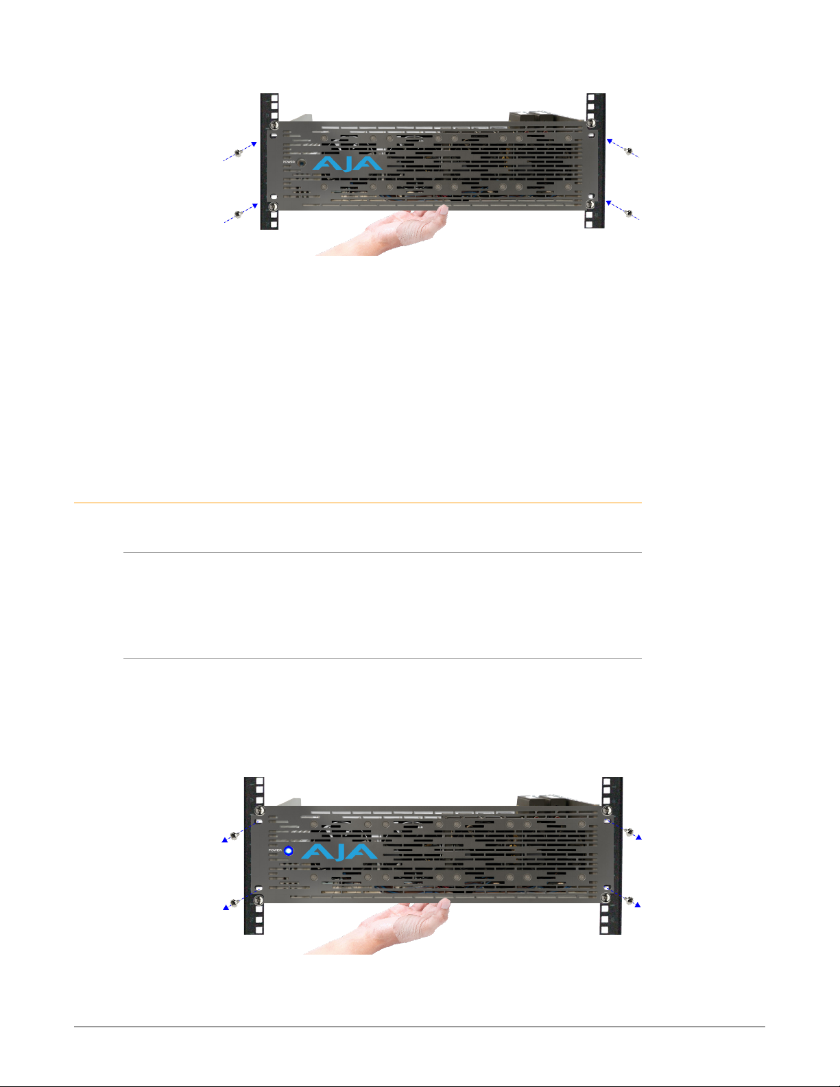
Figure 19. Attaching an Active Faceplate
6. If you have access inside the DRM2 after the faceplate has been secured,
such as through an open rack in the rear, then double-check that all fans are
clear of wires by inspecting them from behind. If found, re-position the DC
wires as needed.
7. While still accessing the rear of the rack, you can also check that no wires
were inadvertently pinched between the faceplate and the DRM2 frame. If
any pinched wires are found, simply loosen the rack mount screws slightly,
remove the wire(s) then re-tighten the rack screws.
8. If not previously connected, connect the AC Power Cord to the rear of the
DRM2 power supply and plug it into a suitable 100–240VAC outlet.
Uninstallation
Remove Passive Faceplate
1. Remove the four inner screws which hold the faceplate on the DRM2.
2. Remove the faceplate from the DRM2 and set it aside.
Remove Active Faceplate
1. Remove the four inner screws which hold the faceplate on the DRM2.
2. While removing the mounting screws, be sure to also support the faceplate
Figure 20. Removing an Active Faceplate
Keep these screws on hand for re-installation later.
Keep these screws on hand for re-installation later.
to prevent it from falling while still connected to the main DC Power
Harness.
WARN ING: Do not allow the Active Faceplate to fall, nor to hang by its DC power
connection. This could damage the faceplate DC power connection and/or
the main DC Power Harness.
DRM2 Mini-Converter Rack-Mount Frame Manual v1.0 14 www.aja.com
Page 15

3. Remove the faceplate from the DRM2 frame, while supporting the faceplate.
4. While still supporting the faceplate, unplug the faceplate's DC power
connector from the DRM2 DC Power Harness. Do this by gently twisting
counterclockwise and then pulling the connector out. If possible when
pulling it out, hold by the connector instead of by the cable.
Figure 21. Locate and unplug the Active Faceplate DC power connector
5. Set aside the Active Faceplate for re-installation later.
WARN ING: When handling an Active Faceplate, keep it free of contact from dust,
particles, wire fragments or other debris, because such contamination could
cause a loud fan noise, or cause a fan failure when power is applied.
Remove Carrier from DRM2 Frame
NOTE: When working with a frame full of converters it is generally ideal, when possible
to have access from both the front and the rear of the DRM2 frame.
1. Remove the DRM2 faceplate, if one is attached to the frame.
2. If you have access to the rear of the frame, such as through an open chassis,
you may be able to access and remove a Carrier from the rear of the
frame only. Depending upon the ease of the access, and how many other
converters are installed in the frame, this may or may not be convenient.
3. Disconnect DC power, USB, ber and/or AV cables from the mounted MiniConverters (if any).
4. Remove the Carrier Rear Screw (if present). Set it aside for re-installation
later.
5. Loosen the No-Tools Secure Screw at the front of the Carrier, until the Carrier
comes loose.
6. Slide the Carrier slightly forward (towards the front of the frame) to
disengage the Carrier from the rear alignment slot.
7. Lift the Carrier up and out of the frame.
NOTE: Avoid catching the Carrier on other cables inside the DRM2 as you move it out of
the frame.
Remove Rear-Mounted Converter from Carrier
1. If not previously done, remove the Carrier from the DRM2 frame (see
"Remove Carrier from DRM2 Frame" on page 15.)
2. From the rear side of the Carrier's vertical bracket, remove the rearmounting screws from the converter, and set them aside for future use.
3. Remove the converter from Carrier.
DRM2 Mini-Converter Rack-Mount Frame Manual v1.0 15 www.aja.com
Page 16
Remove Bottom-Mounted Converter from Carrier
1. If not previously done, remove the Carrier from the DRM2 frame (see
"Remove Carrier from DRM2 Frame" on page 15.)
2. From the underside of the Carrier, remove the bottom housing screws from
the Mini-Converter, and set them aside.
3. Remove the converter from the Carrier.
4. Re-insert the bottom housing screws into the carrier bottom edge of its
housing.
Special Case Installations
Mounting Converters with DIP Switches
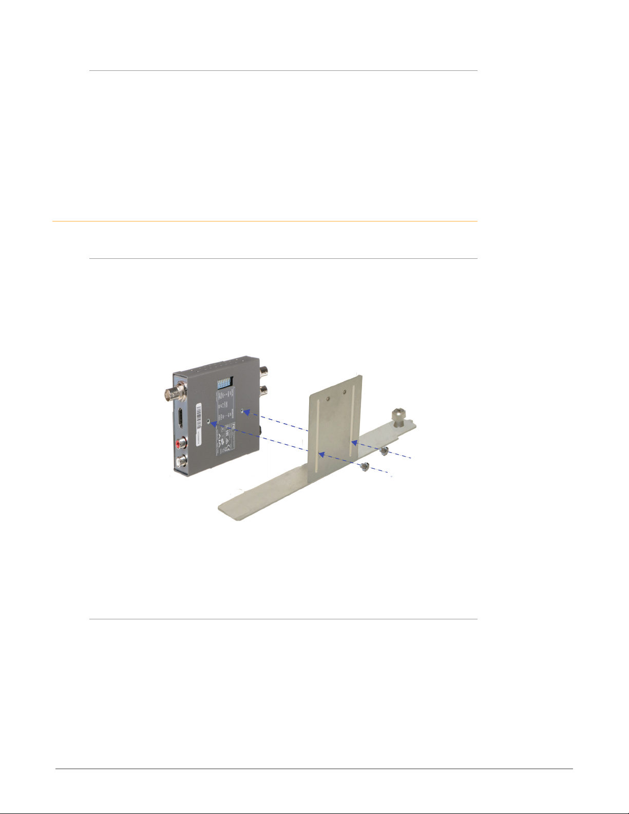
If the Mini-Converter being installed has DIP switches, these are usually found
on the rear of the converter, located between the two rear mounting holes. The
DIP switches will be covered by the Carrier's converter mounting bracket after
the converter is installed onto it, making DIP adjustments impossible (while
mounted). Thus a best practice is to adjust your DIP switches first, then mount the
converter onto the Carrier.
Figure 22. Mounting a Mini-Converter with DIPS onto a Carrier bracket
When the Mini-Converter is connected to a host computer, in most cases the
same functional adjustments (and more) can be made using AJA's Mini-Config
software alone, instead of using the physical DIP switches.
NOTE: See "USB Connections" on page 19.
Stacking FiDO Converters Two-High
Two FiDO Mini-Converters, given their thermal characteristics, may be
mounted directly on top of each other on a single DRM2 Carrier and thus the
two converters will use only one Carrier slot in the DRM2 frame. Only the AJA
FiDO and FiDO-2(T/R/TR) Mini-Converters are certified for this vertical-stacked
configuration on a Carrier.
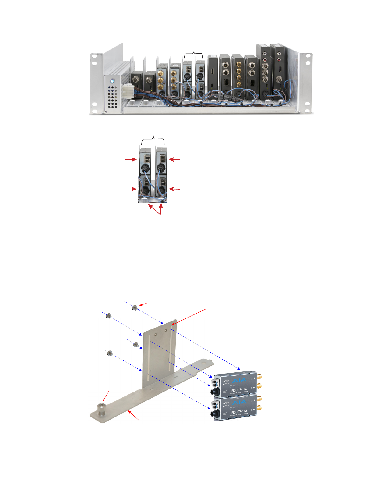
Below is an example DRM2 configuration with two stacked FiDOs in the frame.
DRM2 Mini-Converter Rack-Mount Frame Manual v1.0 16 www.aja.com
Page 17
Stacked FiDOs
FiDO TR-12G
FiDO TR-12G
FiDO TR-12G
FiDO TR-12G
Two (2) Carriers
Figure 23. DRM2 with four FiDO Mini-Converters using two Carrier Slots
Stacked FiDOs
Figure 24. Four FiDO TR-12G Mini-Converters using two Carrier Slots
FiDOs have rear mounting holes, so those are used to attach them to Carriers.
1. Use the converter mounting slots and mounting screws to install the rst
FiDO Mini-Converter to the bracket.
2. Slide it to the bottom against the Carrier.
3. Tighten its mounting screws.
4. Install the second FiDO above the rst one, using another pair of mounting
screws through the slots into the rear of the second FiDO.
Figure 25. Stacking two FiDO Mini-Converters onto one Carrier bracket
Mounting Screws
No-Tools
Secure Screw
Converter
Mounting Slots
Mounting Bracket
Carrier
5. Install the Carrier with the two FiDOs into the DRM2 in the usual way.
NOTE: See "Installing Carriers with Converters into the DRM2 Frame" on page 11.
DRM2 Mini-Converter Rack-Mount Frame Manual v1.0 17 www.aja.com
Page 18
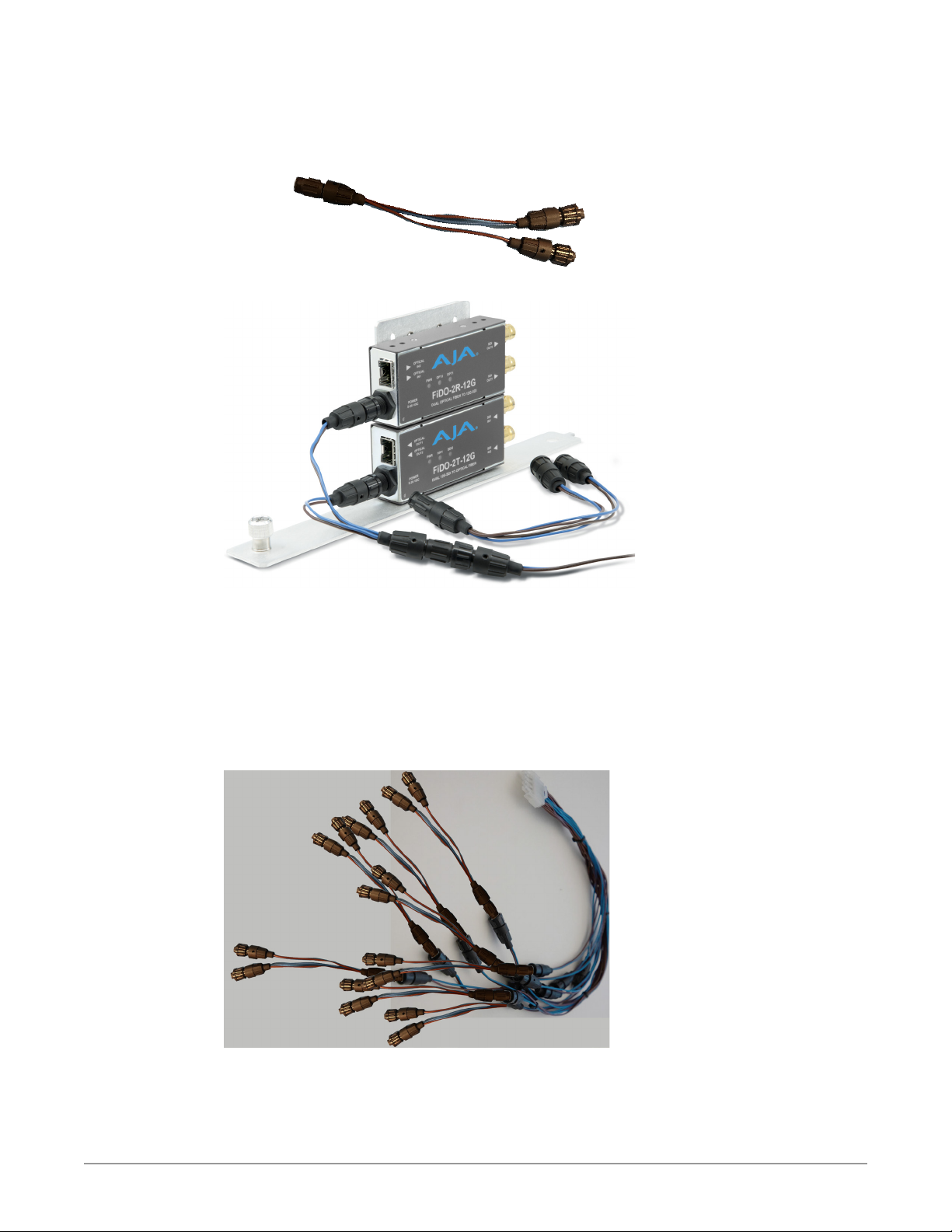
Depending on how many and what mix of converters you are installing into the
frame, you may need to add a DC Power Y-Cable for the additional converters.
These are simply added to any power connector on the main DC Power Harness.
Figure 26. AJA DC Power Y-Cable (optional)
Figure 27. Y-Cable added to DC Power Harness for stacked FiDO expansion
For installing the maximum of 24 FiDOs continue below.
6. Proceed to mount up to a total of 12 pairs of stacked FiDO Mini-Converters
onto 12 Carriers.
7. Install the dual-FiDO Carriers into the DRM2 frame in the usual way.
8. Connect an AJA DC Power Y-Cable to all 12 of the DC connectors on the
DRM2 main DC Power Harness. This will provide 24 DC power cables and
connectors, supporting the maximum setup of 24 FiDOs.
Figure 28. Adding up to 12 Y-Cables to the main DC Power Harness
9. Connect the (up to) 24 Y-Cable power connectors to the (up to) 24 FiDO
Mini-Converters.
10. Connect ber and other remaining cables to the FiDO Mini-Converters as
appropriate.
DRM2 Mini-Converter Rack-Mount Frame Manual v1.0 18 www.aja.com
Page 19
USB Connections
Below we describe use of USB hubs. USB may also be managed by KVM or KVM
over IP, which are the beyond the scope of this manual.
USB Hub
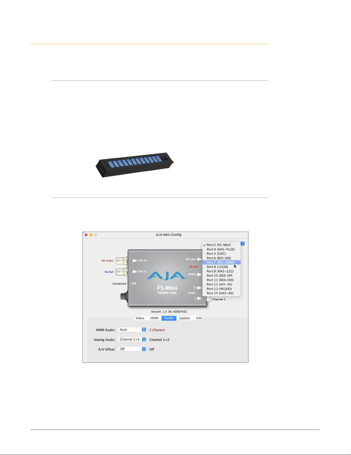
There is no disadvantage to using a USB hub for Mini-Converters installed in a
DRM2 frame, provided some good practices are employed:
• Use an actively-powered hub (one with an AC/DC adapter; not bus-powered).
• Use a high-quality hub, rated as compliant with USB v2.0 or higher.
• A USB v2.0 cable up to ten foot long may be used for the host computer
connection.
• USB from the hub may also be extended by a suitable type of powered
USB 2.0 (or higher) extender.
Figure 29. Example of a typical powered USB v2.0, 12-port hub
AJA Mini-Config USB Device Select
When using AJA Mini-Config software and a USB hub, all of a DRM2 frame's
connected and powered Mini-Converters may be conveniently accessed from the
device select menu:
Figure 30. Mini-Config device select menu for DRM2 frame with 12 devices
DRM2 Mini-Converter Rack-Mount Frame Manual v1.0 19 www.aja.com
Page 20

Appendix A – Specifications
DRM2 Tech Specs
User Interface
• 12x mounting slots for any AJA Mini-Converters
• Converters may be installed without removing the frame from the rack
Size (w x d x h)
• 19.0" x 15.0" x 5.25" (48.26x 38.1cmx 13.34 cm)
Weight
• DRM2 w/12 Carriers, hardware, power harness, and power cord: 9.3 lbs (4.2 kg)
• DRM2 Faceplate w/o fans .9 lbs (.4 kg)
• DRM2 Faceplate w fans 2.1 lbs (.9 kg)
Power
Environment
• Universal 100-240V, 50/60Hz power input
• 12x +5V DC regulated outputs (hardwired to power supply)
• Power Consumption: 200 Watts maximum
NOTE: the total power required by all the installed AJA Mini-Converters must
be less than the DRM2 frame maximum of 200 Watts. Refer to the individual
AJA Mini-Converter Tech Specs Power section, available on the AJA website, to
calculate the total power for the DRM2 converter configuration.
• Operating Temperature: 0 to 40 C (32 to 104 F)
• Safe Storage Temperature (Power Off): -40 to 60 C (-40 to 140 F)
• Operating Relative Humidity: 10-90% non-condensing
• Operating Altitude: <2,500 meters (<8,000 feet)
DRM2 Mini-Converter Rack-Mount Frame Manual v1.0 20 www.aja.com
Page 21

Appendix B – Safety and Compliance
Federal Communications Commission (FCC) Compliance Notices
Class A Interference Statement
This equipment has been tested and found to comply with the limits for a Class
A digital device, pursuant to Part 15, Subpart B of the FCC Rules. These limits
are designed to provide reasonable protection against harmful interference
in a residential installation. This equipment generates, uses, and can radiate
radio frequency energy and, if not installed and used in accordance with the
instructions, may cause harmful interference to radio communications. However,
there is no guarantee that interference will not occur in a particular installation. If
this equipment does cause harmful interference to radio or television reception,
which can be determined by turning the equipment off and on, the user is
encouraged to try to correct the interference by one or more of the following
measures:
• Reorient or relocate the receiving antenna.
• Increase the separation between the equipment and receiver.
• Connect the equipment into an outlet on a circuit different from that to which
the receiver is connected.
• Consult the dealer or an experienced radio/TV technician for help.
FCC Caution
This device complies with Part 15 of the FCC Rules. Operation is subject to the
following two conditions: (1) This device may not cause harmful interference, and
(2) this device must accept any interference received, including interference that
may cause undesired operation.
Canadian ICES Statement
Canadian Department of Communications Radio Interference Regulations
This digital apparatus does not exceed the Class A limits for radio-noise emissions
from a digital apparatus as set out in the Radio Interference Regulations of
the Canadian Department of Communications. This Class A digital apparatus
complies with Canadian ICES-003.
Règlement sur le brouillage radioélectrique du ministère des Communications
Cet appareil numérique respecte les limites de bruits radioélectriques visant les
appareils numériques de classe A prescrites dans le Règlement sur le brouillage
radioélectrique du ministère des Communications du Canada. Cet appareil
numérique de la Classe A est conforme à la norme NMB-003 du Canada.
DRM2 Mini-Converter Rack-Mount Frame Manual v1.0 21 www.aja.com
Page 22
European Union, European Free Trade Association (EFTA) and
United Kingdom Regulatory Compliance
This equipment may be operated in the countries that comprise the member
countries of the European Union, European Free Trade Association and the United
Kingdom. These countries, listed in the following paragraph, are referred to as
The European Community throughout this document:
AUSTRIA, BELGIUM, BULGARIA, CROATIA, CZECH REPUBLIC, DENMARK, ESTONIA,
FINLAND, FRANCE, GERMANY, GREECE, HUNGARY, ICELAND, IRELAND, ITALY,
LATVIA, LIECHTENSTEIN, LITHUANIA, LUXEMBOURG, MALTA, NETHERLANDS,
NORWAY, POLAND, PORTUGAL, REPUBLIC OF CYPRUS, ROMANIA, SLOVAK
REPUBLIC, SLOVENIA, SPAIN, SWEDEN, SWITZERLAND, UNITED KINGDOM
Declaration of Conformity
Marking by these symbols indicates compliance with the Essential Requirements
of the EMC Directive of the European Union 2014/30/EU.
This equipment meets the following conformance standards:
Safety
EN 62368-1: 2014 + A11 (T-Mark License),
IEC 62368-1: 2014 (CB Scheme Report/Certificates)
Emissions
EN 55032: 2015 + A11: 2020, CISPR 32: 2015,
EN 61000-3-2: 2014, EN 61000-3-3: 2013
Immunity
EN 55035: 2017 + A11: 2020, EN 61000-4-2:2009,
EN 61000-4-3:2006+A1:2008 +A2:2010,
EN 61000-4-4: 2012, EN 61000-4-5: 2014 +A1: 2017, EN 61000-4-6: 2014,
EN 61000-4-11: 2020
Environments: E2, E3 and E4
The product is also licensed for additional country specific standards as required
for the International Marketplace.
Warning! This is a Class A product. In a domestic environment, this product
may cause radio interference, in which case, the user may be required to take
appropriate measures.
Achtung! Dieses ist ein Gerät der Funkstörgrenzwertklasse A. In Wohnbereichen
können bei Betrieb dieses Gerätes Rundfunkstörungen auftreten, in welchen
Fällen der Benutzer für entsprechende Gegenmaßnahmen verantwortlich ist.
Attention! Ceci est un produit de Classe A. Dans un environnement domestique,
ce produit risque de créer des interférences radioélectriques, il appartiendra
alors à l'utilisateur de prendre les mesures spécifiques appropriées.
DRM2 Mini-Converter Rack-Mount Frame Manual v1.0 22 www.aja.com
Page 23
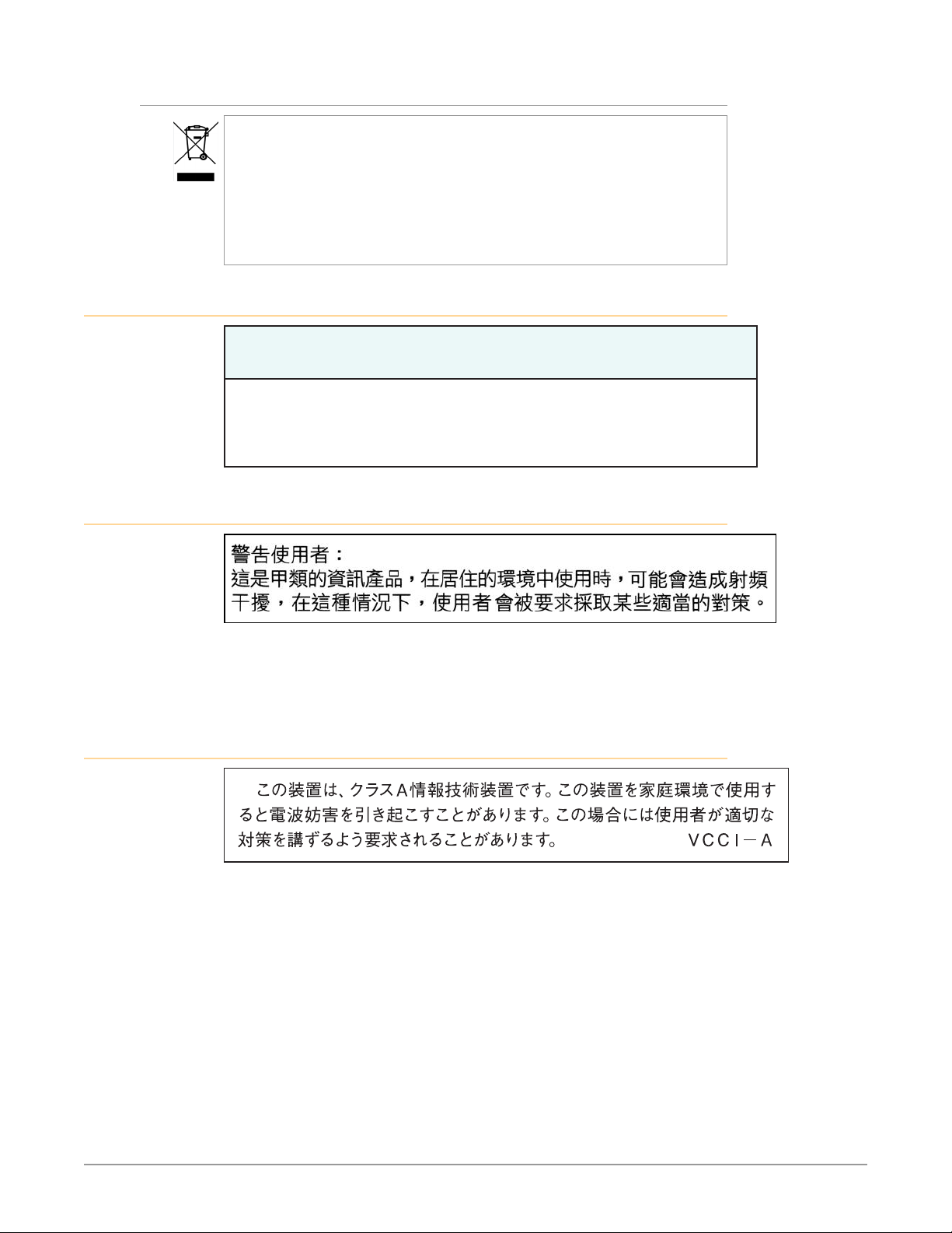
Recycling Notice
This symbol on the product or its packaging indicates that this product
must not be disposed of with your other household waste. Instead, it is your
responsibility to dispose of your waste equipment by handing it over to a
designated collection point for the recycling of waste electrical and electronic
equipment. The separate collection and recycling of your waste equipment
at the time of disposal will help conserve natural resources and ensure that
it is recycled in a manner that protects human health and the environment.
For more information about where you can drop off your waste for recycling,
please contact your local authority, or where you purchased your product.
Korea KCC Compliance Statement
넩 韥韥鱉 꽺ꓩ끞 쀍陲꾅 ꩡ끞뼕 ꑞ놶냱ꈑ 놶뼞ꫦ뵾閵ꌱ ꗐ냵 韥韥ꈑ 閵뇊
끞 쀍陲꾅 ꩡ끞뼍鱉 陲끥 놹볁閹ꫢ넍 끥ꇙ閵 넽걪鱽鲙.
Taiwan Compliance Statement
This is a Class A product based on the standard of the Bureau of Standards,
Metrology and Inspection (BSMI) CNS 13438, Class A. In a domestic environment
this product may cause radio interference in which case the user may be required
to take adequate measures.
Japan Compliance Statement
ꩡ 끞 녅 껽 驩 ꓭ
This is a Class A product based on the standard of the VCCI Council (VCCI32:2016).
If this equipment is used in a domestic environment, radio interference may
occur, in which case, the user may be required to take corrective actions.
I
DRM2 Mini-Converter Rack-Mount Frame Manual v1.0 23 www.aja.com
Page 24
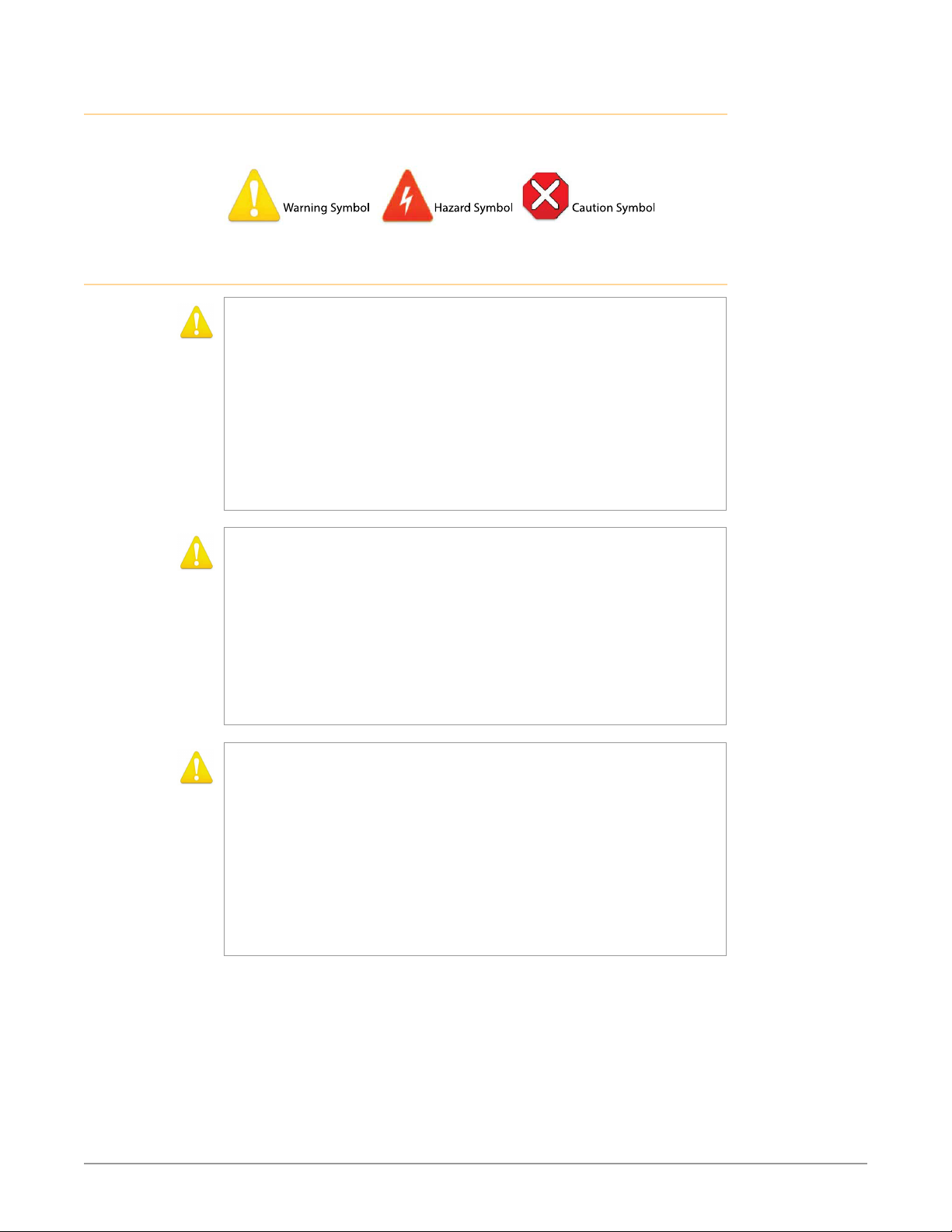
Translated Warning and Caution Messages
The following caution statements, warning conventions, and warning messages
apply to this product and manual.
Before Operation Please Read These Instructions
Warning! Read and follow all warning notices and instructions marked on the
product or included in the documentation.
Avertissement! Lisez et conformez-vous à tous les avis et instructions
d'avertissement indiqués sur le produit ou dans la documentation.
Warnung! Lesen und befolgen Sie die Warnhinweise und Anweisungen, die auf
dem Produkt angebracht oder in der Dokumentation enthalten sind.
¡Advertencia! Lea y siga todas las instrucciones y advertencias marcadas en el
producto o incluidas en la documentación.
Aviso! Leia e siga todos os avisos e instruções assinalados no produto ou incluídos
na documentação.
Avviso! Leggere e seguire tutti gli avvisi e le istruzioni presenti sul prodotto o
inclusi nella documentazione.
Warning! Do not use this device near water and clean only with a dry cloth.
Avertissement! N'utilisez pas cet appareil près de l'eau et nettoyez-le seulement
avec un tissu sec.
Warnung! Das Gerät nicht in der Nähe von Wasser verwenden und nur mit einem
trockenen Tuch säubern.
¡Advertencia! No utilice este dispositivo cerca del agua y límpielo solamente con
un paño seco.
Aviso! Não utilize este dispositivo perto da água e limpe-o somente com um pano
seco.
Avviso! Non utilizzare questo dispositivo vicino all'acqua e pulirlo soltanto con un
panno asciutto.
Warning! Do not block any ventilation openings. Install in accordance with the
manufacturer's instructions.
Avertissement! Ne bloquez aucune ouverture de ventilation. Suivez les
instructions du fabricant lors de l'installation.
Warnung! Die Lüftungsöffnungen dürfen nicht blockiert werden. Nur gemäß den
Anweisungen des Herstellers installieren.
¡Advertencia! No bloquee ninguna de las aberturas de la ventilación. Instale de
acuerdo con las instrucciones del fabricante.
Aviso! Não obstrua nenhuma das aberturas de ventilação. Instale de acordo com as
instruções do fabricante.
Avviso! Non ostruire le aperture di ventilazione. Installare in conformità con le
istruzioni del fornitore.
DRM2 Mini-Converter Rack-Mount Frame Manual v1.0 24 www.aja.com
Page 25

Warning! Do not install near any heat sources such as radiators, heat registers,
stoves, or other apparatus (including amplifiers) that produce heat.
Avertissement! N'installez pas l'appareil près d'une source de chaleur telle que des
radiateurs, des bouches d'air de chauffage, des fourneaux ou d'autres appareils
(amplificateurs compris) qui produisent de la chaleur.
Warnung! Nicht in der Nähe von Wärmequellen wie Heizkörpern, Heizregistern,
Öfen oder anderen Wärme erzeugenden Geräten (einschließlich Verstärkern)
aufstellen.
¡Advertencia! No instale cerca de fuentes de calor tales como radiadores, registros
de calor, estufas u otros aparatos (incluidos amplificadores) que generan calor.
Aviso! Não instale perto de nenhuma fonte de calor tal como radiadores, saídas
de calor, fogões ou outros aparelhos (incluindo amplificadores) que produzam
calor.
Avviso! Non installare vicino a fonti di calore come termosifoni, diffusori di aria
calda, stufe o altri apparecchi (amplificatori compresi) che emettono calore.
Warning! Do not defeat the safety purpose of the polarized or grounding-
type plug. A polarized plug has two blades with one wider than the other. A
grounding type plug has two blades and a third grounding prong. The wide
blade or the third prong are provided for your safety. If the provided plug does
not fit into your outlet, consult an electrician for replacement of the obsolete
outlet.
Avertissement! La sécurité de la prise polarisée ou de la prise de type mise à la
terre ne doit en aucun cas être empêchée de fonctionner. Une prise polarisée
a deux broches, l'une étant plus large que l'autre. Une prise de type mise à la
terre a deux broches et une troisième broche pour la mise à la terre. La broche
large ou la troisième broche sont fournies pour votre sécurité. Si la prise
fournie ne s'insère pas dans votre prise femelle, consultez un électricien pour le
remplacement de la prise femelle obsolète.
Warnung! Der Sicherheitszweck des gepolten bzw. Schukosteckers ist zu
berücksichtigen. Ein gepolter Stecker verfügt über zwei Pole, von denen einer
breiter als der andere ist. Ein Schukostecker verfügt neben den zwei Polen noch
über einen dritten Pol zur Erdung. Der breite Pol bzw. der Erdungspol dienen der
Sicherheit. Wenn der zur Verfügung gestellte Stecker nicht in Ihren Anschluss
passt, konsultieren Sie einen Elektriker, um den veralteten Anschluss zu ersetzen.
¡Advertencia! No eche por tierra la finalidad del tipo de enchufe polarizado con
conexión a tierra. Un enchufe polarizado tiene dos espigas, una más ancha
que la otra. Un enchufe con conexión a tierra tiene dos espigas iguales y una
tercera espiga que sirve para la conexión a tierra. La expiga ancha, o la tercera
espiga, sirven para su seguridad. Si el enchufe suministrado no encaja en el
tomacorriente, consulte con un electricista para reemplazar el tomacorriente
obsoleto.
Aviso! Não anule a finalidade da segurança da ficha polarizada ou do tipo ligação
terra. Uma ficha polarizada tem duas lâminas sendo uma mais larga do que
a outra. Uma ficha do tipo de ligação à terra tem duas lâminas e um terceiro
terminal de ligação à terra. A lâmina larga ou o terceiro terminal são fornecidos
para sua segurança. Se a ficha fornecida não couber na sua tomada, consulte um
electricista para a substituição da tomada obsoleta.
Avviso! Non compromettere la sicurezza della spina polarizzata o con messa a
terra. Una spina polarizzata ha due spinotti, di cui uno più largo. Una spina con
messa a terra ha due spinotti e un terzo polo per la messa a terra. Lo spinotto
largo o il terzo polo sono forniti per motivi di sicurezza. Se la spina fornita non
si inserisce nella presa di corrente, contattare un elettricista per la sostituzione
della presa obsoleta.
DRM2 Mini-Converter Rack-Mount Frame Manual v1.0 25 www.aja.com
Page 26

Warning! Since the Mains plug is used as the disconnection for the device, it must
remain readily accessible and operable.
Avertissement! Puisque la prise principale est utilisée pour débrancher l'appareil,
elle doit rester aisément accessible et fonctionnelle.
Warnung! Da der Netzstecker als Trennvorrichtung dient, muss er stets zugänglich
und funktionsfähig sein.
¡Advertencia! Puesto que el enchufe de la red eléctrica se utiliza como dispositivo
de desconexión, debe seguir siendo fácilmente accesible y operable.
Aviso! Dado que a ficha principal é utilizada como a desconexão para o dispositivo,
esta deve manter-se prontamente acessível e funcional.
Avviso! Poiché il cavo di alimentazione viene usato come dispositivo di
sconnessione, deve rimane prontamente accessibile e operabile.
Warning! Protect the power cord from being walked on or pinched particularly at
plugs, convenience receptacles, and the point where they exit from the device.
Avertissement! Protégez le cordon d'alimentation pour que l'on ne marche
pas dessus ou qu'on le pince, en particulier au niveau des prises mâles, des
réceptacles de convenance, et à l'endroit où il sort de l'appareil.
Warnung! Vermeiden Sie, dass auf das Netzkabel getreten oder das Kabel geknickt
wird, insbesondere an den Steckern, den Steckdosen und am Kabelausgang am
Gerät.
¡Advertencia! Proteja el cable de energía para que no se le pise ni apriete, en
especial cerca del enchufe, los receptáculos de conveniencia y el punto del que
salen del equipo.
Aviso! Proteja o cabo de alimentação de ser pisado ou de ser comprimido
particularmente nas fichas, em tomadas de parede de conveniência e no ponto
de onde sai do dispositivo.
Avviso! Proteggere il cavo di alimentazione in modo che nessuno ci cammini sopra
e che non venga schiacciato soprattutto in corrispondenza delle spine e del
punto in cui esce dal dispositivo.
Warning! Unplug this device during lightning storms or when unused for long
periods of time.
Avertissement! Débranchez cet appareil pendant les orages avec éclairsou s'il est
inutilisé pendant de longues périodes.
Warnung! Das Gerät ist bei Gewitterstürmen oder wenn es über lange Zeiträume
ungenutzt bleibt vom Netz zu trennen.
¡Advertencia! Desenchufe este dispositivo durante tormentas eléctricas o cuando
no se lo utilice por largos periodos del tiempo.
Aviso! Desconecte este dispositivo da tomada durante trovoadas ou quando não é
utilizado durante longos períodos de tempo.
Avviso! Utilizzare soltanto i collegamenti e gli accessori specificati e/o venduti dal
produttore, quali il treppiedi e l'esoscheletro.
DRM2 Mini-Converter Rack-Mount Frame Manual v1.0 26 www.aja.com
Page 27

Warning! Refer all servicing to qualified service personnel. Servicing is required
when the device has been damaged in any way, such as power-supply cord or
plug is damaged, liquid has been spilled or objects have fallen into the device,
the device has been exposed to rain or moisture, does not operate normally, or
has been dropped.
Avertissement! Référez-vous au personnel de service qualifié pour tout entretien.
L'entretien est exigé quand l'appareil a été endommagé de quelque manière
que ce soit, par exemple lorsque le cordon d'alimentation ou la prise sont
endommagés, que du liquide a été versé ou des objets sont tombés dans
l'appareil, que l'appareil a été exposé à la pluie ou à l'humidité, ne fonctionne pas
normalement ou est tombé.
Warnung! Das Gerät sollte nur von qualifizierten Fachkräften gewartet werden.
Eine Wartung ist fällig, wenn das Gerät in irgendeiner Weise beschädigt wurde,
wie bei beschädigtem Netzkabel oder Netzstecker, falls Flüssigkeiten oder
Objekte in das Gerät gelangen, das Gerät Regen oder Feuchtigkeit ausgesetzt
wurde, nicht ordnungsgemäß funktioniert oder fallen gelassen wurde.
¡Advertencia! Consulte al personal calificado por cuestiones de reparación. El
servicio de reparación se requiere cuando el dispositivo ha recibido cualquier
tipo de daño, por ejemplo cable o espigas dañadas, se ha derramado líquido o
se han caído objetos dentro del dispositivo, el dispositivo ha sido expuesto a la
lluvia o humedad, o no funciona de modo normal, o se ha caído.
Aviso! Remeta todos os serviços de manutenção para o pessoal de assistência
qualificado. A prestação de serviços de manutenção é exigida quando o
dispositivo foi danificado mediante qualquer forma, como um cabo de
alimentação ou ficha que se encontra danificado/a, quando foi derramado
líquido ou caíram objectos sobre o dispositivo, quando o dispositivo foi exposto
à chuva ou à humidade, quando não funciona normalmente ou quando foi
deixado cair.
Avviso! Fare riferimento al personale qualificato per tutti gli interventi di assistenza.
L'assistenza è necessaria quando il dispositivo è stato danneggiato in qualche
modo, ad esempio se il cavo di alimentazione o la spina sono danneggiati, è
stato rovesciato del liquido è stato rovesciato o qualche oggetto è caduto nel
dispositivo, il dispositivo è stato esposto a pioggia o umidità, non funziona
correttamente o è caduto.
Warning! Disconnect the external AC power supply line cord(s) from the mains
power before moving the unit.
Avertissement! Retirez le ou les cordons d’alimentation en CA de la source
d’alimentation principale lorsque vous déplacez l’appareil.
Warnung! Trennen Sie die Wechselstrom-Versorgungskabel vom Netzstrom, bevor
Sie das Gerät verschieben.
¡Advertencia! Cuando mueva la unidad desenchufe de la red eléctrica el/los
cable(s) de la fuente de alimentación CA tipo brick.
Advertência! Remova os cabos CA de alimentação brick da rede elétrica ao mover
a unidade.
Avvertenza! Scollegare il cavo dell’alimentatore quando si sposta l’unità.
Warning! Only use attachments and accessories specified and/or sold by the
manufacturer.
Avertissement! Utilisez seulement les attaches et accessoires spécifiés et/ou
vendus par le fabricant.
Warnung! Verwenden Sie nur Zusatzgeräte und Zubehör angegeben und / oder
verkauft wurde durch den Hersteller.
¡Advertencia! Utilice solamente los accesorios y conexiones especificados y/o
vendidos por el fabricante.
Aviso! Utilize apenas equipamentos/acessórios especificados e/ou vendidos pelo
fabricante.
Avviso! Utilizzare soltanto i collegamenti e gli accessori specificati e/o venduti dal
produttore.
DRM2 Mini-Converter Rack-Mount Frame Manual v1.0 27 www.aja.com
Page 28

Hazard! High Voltage. This situation or condition can cause injury due to electric
shock.
Avertissement! Tension élevée. Cette situation ou condition peut causer des
blessures dues à un choc électrique.
Warnung! Hochspannung. Diese Situation oder Bedingung kann zu Verletzungen
durch Stromschlag führen.
¡Advertencia! Alto voltaje . Esta situación o condición puede causar lesiones
debidas a una descarga eléctrica.
Aviso! Alta Tensão . Esta situação ou condição pode causar danos devido a
choques elétricos.
Avviso! Alta tensione. Questa situazione o condizione può causare lesioni a causa
di scosse elettriche.
DRM2 Mini-Converter Rack-Mount Frame Manual v1.0 28 www.aja.com
Page 29

Warranty and Liability Information
Limited Warranty
AJA Video Systems, Inc. (AJA Video) warrants that this product will be free from defects
in materials and workmanship for a period of five years from the date of purchase. If a
product proves to be defective during this warranty period, AJA Video, at its option, will
either repair the defective product without charge for parts and labor, or will provide a
replacement in exchange for the defective product.
In order to obtain service under this warranty, you the Customer, must notify AJA
Video of the defect before the expiration of the warranty period and make suitable
arrangements for the performance of service.The Customer shall be responsible for
packaging and shipping the defective product to a designated service center nominated
by AJA Video, with shipping charges prepaid. AJA Video shall pay for the return of the
product to the Customer if the shipment is to a location within the country in which
the AJA Video service center is located. Customer shall be responsible for paying all
shipping charges, insurance, duties, taxes, and any other charges for products returned
to any other locations.
This warranty shall not apply to any defect, failure or damage caused by improper
use or improper or inadequate maintenance and care. AJA Video shall not be
obligated to furnish service under this warranty a) to repair damage resulting from
attempts by personnel other than AJA Video representatives to install, repair or
service the product, b)to repair damage resulting from improper use or connection to
incompatibleequipment, c) to repair any damage or malfunction caused by the use of
non-AJA Videoparts or supplies, or d) to service a product that has been modified or
integrated withother products when the effect of such a modification or integration
increases the timeor difficulty of servicing the product.
THIS WARRANTY IS GIVEN BY AJA VIDEO IN LIEU OF ANY OTHER WARRANTIES, EXPRESS
OR IMPLIED. AJA VIDEO AND ITS VENDORS DISCLAIM ANY IMPLIED WARRANTIES
OF MERCHANTABILITY OR FITNESS FOR A PARTICULAR PURPOSE. AJA VIDEO’S
RESPONSIBILITY TO REPAIR OR REPLACE DEFECTIVE PRODUCTS IS THE WHOLE AND
EXCLUSIVE REMEDY PROVIDED TO THE CUSTOMER FOR ANY INDIRECT, SPECIAL,
INCIDENTAL OR CONSEQUENTIAL DAMAGES IRRESPECTIVE OF WHETHER AJA VIDEO OR
THE VENDOR HAS ADVANCE NOTICE OF THE POSSIBILITY OF SUCH DAMAGES.
DRM2 Mini-Converter Rack-Mount Frame Manual v1.0 29 www.aja.com
Page 30

Index
A
Active Faceplate 5
AJA Mini-Config 19
AJA Support 2
Attach an Active Faceplate 13
Attach an Passive Faceplate 12
B
Basic Order 7
C
Configure Carrier Bracket(s) 11
Converters into the DRM2 Frame 11
D
Dimensions 20
E
Environment 20
F
Features 5
Front Faceplates 5
H
High Capacity 4
I
Included in the box
Installation 7, 9
Install Carriers into the DRM2 Frame
11
Installing Carriers with Converters
11
Installing Converters into the DRM2
Frame 11
M
Mini-Converter Carriers 8
Mini-Converter Frame for 19-inch
Racks 4
Mini-Converter Mounting Carriers 8
Mini-Converter Mounting Hardware
8
Mounting 24 FIDO Converters 16
Mounting Converters onto Carriers
9
Mounting Converters with DIP
Switches 16
Mounting Mini-Converters using
bottom holes 10
Mounting Mini-Converters using
rear holes 10
P
Parts Available Separately 7
Passive Faceplate 5
Power 20
R
Rack Mount Frame 8
Rack Mount Frame with Carrier
Slots 8
Remove Active Faceplate 14
Remove Bottom-Mounted Converter
from Carrier 16
Remove Carrier from DRM2 Frame
15
Remove Passive Faceplate 14
Remove Rear-Mounted Converter
from Carrier 15
Replace the front faceplate 13
S
Safety and Compliance 21
Separately Available Parts
Special Case Installations 16
Specifications 20
Stacking FiDO Converters Two-high
on Carriers 16
T
Twelve Mini-Converters Example
Configuration 9
U
USB Connections 19
USB Device Select 19
USB Hub 19
W
Warranty and Liability 29
O
Overview 4
Overview of Installation 8
DRM2 Mini-Converter Rack-Mount Frame Manual v1.0 30 www.aja.com
 Loading...