

Page 1
XR-MD100
U(S),K(S)
XR-MD101
EZ(S)
SERVICE MANUAL
• BASIC TAPE MECHANISM : 2ZM-1 YR9
MD/CD STEREO SYSTEM
This service manual contains information only on the TEST MODE and ELECTRICAL ADJUSTMENT
For more information, please refer to the following service manuals.
XR-MD100 U<S> (S/M Code No.09-993-315-0R1)
XR-MD100 K<S>/MD101 EZ<S> (S/M Code No.09-993-315-0R3)
<CD SECTION> of XR-MD100(U,K)/MD101(EZ).
• BASIC CD MECHANISM : 3ZG-3 E3N
• BASIC MD MECHANISM : 7ZG-9 YB
.
S/M Code No. 09-993-315-0S1
SUPPLEMENT
DATA
Page 2
TEST MODE
1. CD Test Mode
1-1. Starting Up the CD Test Mode
While pressing the “CD” button, connect the AC plug to the power outlet. When the CD test mode starts up, all displays turn on.
1-2. How to Release the CD Test Mode
To release the CD test mode, press the “POWER” button or the function buttons other than the “CD” button, or disconnect the
AC plug from the power outlet.
1-3. Function Description of the Test Mode
MODE
Start mode
Focus search mode
Play mode
Traverse mode
Sled mode
Operation
CD key + AC
plug IN
STOP key
PLAY key
PAUSE key
F.SKIP key
B.SKIP key
Indication on
display
All indicators light
CD
Track No. and
playing time
(spectrum analyzer)
Track No. and
playing time
CD TEST
Function and movement
• CD TEST mode starts
• All indicators light
• LD lights
• Continuous focus search
• Continuous spindle motor
kick
• Normal playback
• When TOC reading is not
possible, the focus search
continues
• Tracking servo is turned off
• The pickup moves to the
innermost track
• The pickup moves to the
outermost track
Check item
• Check all indicators light
• Microprocessor
• DATA BUS LINE
• APC circuit
• LASER current
• Check the focus search
waveform
• Check the focus error
waveform
• Focus servo circuit
• DRF output
• Spindle servo line
• Same checks as shown in the
above column
• Each servo circuit
• Check the tracking error
waveform
• Tracking circuit
• Sled circuit
• Mechanism (gear and motor)
Note: If the focus search operation is continued for 10 minutes or longer, the driver IC heats up sufficiently to trigger the protection
circuit, which stops the CD system. Turn off the main power and re-start operation about 10 minutes later.
2. MD Test Mode
2-1. Starting Up the MD Test Mode
While pressing the “MD” button, connect the AC plug to the power outlet. About one second later after the MD test mode has
started up, the following message appears and the MD test mode becomes operable.
MD
Note: 1. If operation of the mechanism shows any abnormality during the test mode, disconnect the AC plug immediately.
2. Playback and recording are not possible during the test mode.
3. If a disc cannot be inserted, insert a disc part way and press the “CD 2 MD DIRECT REC” button. The disc can then be
fully inserted.
T
S
ET
2
Page 3
2-2. How to Exit the MD Test Mode
A
L
SV
L
OF F
1) Press the “MD EJECT” button and remove the disc.
2) Disconnect the AC plug from the power outlet.
* If the machine exits the MD test mode by any methods other than the procedure described above, the machine may operate
abnormally when the POWER is turned on next time. If this happens, disconnect the AC plug.
2-3. Operation Check Mode
1) Checks after the test mode has started up
The following playback audio circuits can be checked.
• The circuits that can be checked: ..................... DAC, LINE AMP and HEADPHONE AMP
• Output level: .................................................... 1 kHz, -21 dB
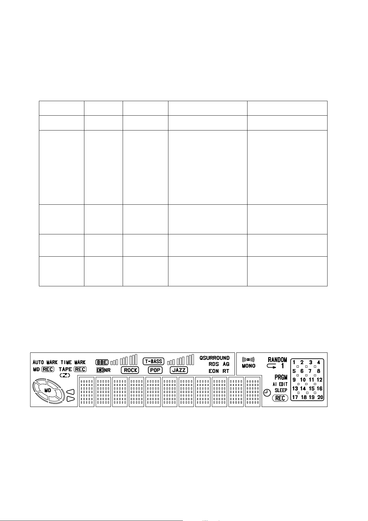
2) Switch status check
The ON/OFF states of the respective switches on the machine and mechanism can be checked on the display.
Switch Name Switch State Indication on display Usable disc
REC PROTECT When the write-protection tab of a disc is closed to ON ROCK Disc for record/playback
REFRECT When the high reflection disc (CD) is used POP Disc for playback only
INNER
3) How to Switch to Servo Standby Mode
When the MD test mode has been established, the mode changes to the servo standby mode and “ALL SV OFF” is displayed
by pressing the 9 button. The various check modes can be entered from this mode. Pressing the 9 button during each
operation returns to “ALL SV OFF”.
When the pickup is at the innermost
track (when the LIMIT switch is ON)
JAZZ —
4) Checking the Sled Operation
The operation of the sled motor and pickup can be checked by pressing the
track) buttons in the “ALL SV OFF” state. “T.SLED FWD” appears while moving to the outermost track and “T.SLED
RVS” appears while moving to the innermost track.
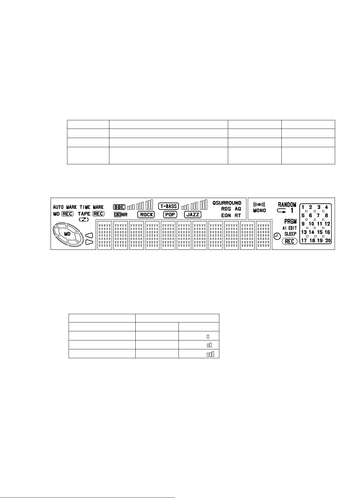
5) Checking the Laser Output
The laser power output level is switched each time the “MD EDIT” button is pressed when “ALL SV OFF” appears and the
operation stops. The laser power output level is repeatedly changed in the order of OFF LASER READ ™ LASER 1/2 ™
LASER WRITE. The indications are as follows.
MODE Indication on display
OFF ALL SV OFF T-BASS
LASER READ LASER READ T-BASS
LASER 1/2 WRITE LASER 1/2 T-BASS
LASER WRITE LASER WRITE T-BASS
* After checking, press the 9 button to return the display to “ALL SV OFF”.
6) Checking the Operation of OWH (Over Write Head)
The OWH operation can be checked in the loading-completed state.
“MD 2 CD” button ............. OWH DOWN
“ / MD EJECT” button......OWH UP
Note: Do not move down the OWH while using a high reflection disc (CD).
6 (to outermost track) and 5 (to innermost
3
Page 4

7) Checking the focus search and spindle kick
• The focus search and the spindle kick can be checked by pressing the
inserting a disc. During checking, the message “FOCUS SEARCH” is displayed.
• After checking these operations, press the 9 button to return the display to “ALL SV OFF”.
8) Checking the focus servo
• Insert a test disc.
• Move the pickup to the center track using the
• Press the “MD MODE” button until the following servo mode is selected in accordance with the inserted disc.
MO disc (MO) .................... Display “SELECT GRV”. (“TIME MARK” lights.)
PIT disc (CD)...................... Display “SELECT PIT”. (“AUTO MARK” lights.)
• Press the W button. If the focus servo is operating normally, the message “FOCUS ON!” is displayed after “FOCUS
SEARCH”.
6 and 5 buttons.
W button in the “ALL SV OFF” state without
FO
• After the checking is completed, press the 9 button to return the display to “ALL SV OFF”.
9) Checking that all servo loops are turned on
• The tracking servo and the sled servo are turned on and all servo loops work when the “ENTER” button is pressed in the
“FOCUS ON!” state.
• If all servo loops are normal, “ALL SV OFF” is displayed.
L
A
• After the checking is completed, press the 9 button to return the display to “ALL SV OFF”.
3. Adjustment Mode
3-1. Temperature Compensation Adjustment
Test point: Check the test point on the display.
Tool: Thermometer
Adjustment procedure:
1) After the MD test mode has started up, press the 9 button to display “ALL SV OFF”.
2) Press the “DISPLAY” button to display “TMP = $⁄⁄”.
3) Press the ; button to display “TMP + **C: + 00”.
4) Put the thermometer near the MD mechanism to measure the room temperature.
5) Adjust the indication value ** using the
the adjustment is complete, press the “ENTER” button.
6) Then, press the 9 button to return the display to “ALL SV OFF”.
7) After the above setting, reduce or add the value indicated by the sharp sign (##) of “TMP + **C: + ##” from or to the value
indicated by the asterisk (**) of “TMP + **C: + ##”. The calculated value must be the room temperature.
S
U
CN
L
5 button and 6 button until the value is the same as the room temperature. After
SV
O
ON
!
Note: Normally, do not perform the temperature compensation adjustment.
4
Page 5

3-2. Laser Power Adjustment
Test point: Pickup laser output
Tool: Laser power meter
Adjustment procedure:
1) Press the “MD EDIT” button three times in the “ALL SV OFF” state to change the display to “LASER WRITE”.
2) Press the ; button to change the display to “LASER = $**”.
3) Adjust the laser power meter so that the value is within 6.8 ±0.03 mW using the
4) After adjustment, press the “ENTER” button and press the 9 button to return the display to “ALL SV OFF”.
Note: If the laser power exceeds 7.0 mW, the pickup may be damaged.
5 button or 6 button.
3-3. Adjustment and Check of Auto Sequence
Test disc: MDW-60, TGYS-1
When adjusting the MO disc:
1) Insert the test disc MDW-60.
2) Press the “MD MODE” button to display “SELECT GRV”.
3) Press the “MD” button to display “AUTO ADJ”. After adjustment, “DONE” appears.
(If “FAILED” is displayed, the adjustment failed.)
4) After the adjustment is completed normally, press the 9 button to return the display to “ALL SV OFF”.
Note: 1. Be sure to use a clean disc because adjustment may be impossible if the disc is dirty or scratched.
2. Be sure to use an MO disc for recording because the writing power of the MO disc is tested and part of the recorded data is
erased.
How to check the IVR, EFB and focus/tracking/sled gain
1) Move the pickup to the center track using the
2) Press the
3) Press the “ENTER” button to switch the mode to “ALL SV ON”.
4) Press the 9 button and press the “DISPLAY” button twice. Then, confirm that the values of “IV$**:EF$⁄⁄” are within the
following ranges.
“**” ................................ 03-07
“⁄⁄” .............................. 09-12
5) Press the “DISPLAY” button again to display “GF** + ##s33”. Confirm that the values of the hexadecimal indication on
display are within the following ranges.
“**” ................................ 20-40
“##” ................................ 15-35
“33” .............................. 15-35
6) After adjustment, press the 9 button to return the display to “ALL SV OFF”.
W button to display “FOCUS ON!”.
5 button and 6 button.
When adjusting the PIT disc:
1) Insert the test disc TGYS-1.
2) Press the “MD MODE” button to display “SELECT PIT”.
3) Press the “MD” button to display “AUTO ADJ”. After adjustment, “DONE” appears.
(If “FAILED” is displayed, the adjustment failed.)
4) After the adjustment is completed normally, press the 9 button to return the display to “ALL SV OFF”. Checking the IVR,
EFB and focus/tracking/sled gain of the PIT disc Confirm that the values on the display are within the following ranges.
“IVR” .............................13-19
“EFB”............................. 09-12
“Focus gain”................... 2A-45
“Tracking gain”.............. 20-40
“Sled gain” ..................... 20-40
5
Page 6

3-4. Checking the Playback Error Rate (PIT disc)
1) Insert the test disc TGYS-1.
2) Move the pickup to the center track using the
3) Press the “MD MODE” button to display “SELECT PIT”.
4) Press the W button to display “FOCUS ON!”.
5) Press the “ENTER” button to display “ALL SV ON”, and press the “DISPLAY” button to confirm that the address display
advances regularly.
6) Press the “DISPLAY” button again to display the playback error rate, and confirm that the value shown by the asterisks
(****) of “Er
7) After adjustment, press the 9 button to return the display to “ALL SV OFF”.
****:####” is “0030” or less.
5 button and 6 button.
3-5. Checking the Record/Playback Error Rate (MO disc)
1) Insert the test disc MDW-60.
2) Move the pickup to the center track using the
3) Press the “CD” button; OWH starts moving and recording from the 600th cluster.
4) After recording for about 15 seconds, press the 9 button to display “ALL SV OFF”
5) Press the “AUX” button to change the mode to “ALL SV ON”, and press the “DISPLAY” button at the 600th cluster. Then,
confirm that the value shown by the asterisks (****) of “Er****:####” is “0020” or less.
6) After adjustment, press the 9 button to return the display to “ALL SV OFF”.
5 button and 6 button.
3-6. UTOC Erase
Perform the following procedure if the recorded disc needs to be erased.
1) Insert the test disc of the UTOC to be erased.
2) Move the pickup to the center track using the 5 button and 6 button.
3) Press the “MD MODE” button to display “SELECT GRV”.
4) Press the “MD REC” button to display “REC Analog”.
5) Press the
6) Press the “ENTER” button to display “ALL SV ON”.
7) Press the “TAPE REC/REC MUTE” button to display “UTOC ERASE”. The UTOC is erased.
8) After the UTOC is erased, “ALL SV OFF” appears on the display.
W button to display “FOCUS ON!”.
6
Page 7

ELECTRICAL ADJUSTMENT
IC1
IC2
RF
VREF
TE
R2
SFR130
CD C.B
C41
R6
C12
C14
1
<CD SECTION>
Note: • Connect a probe (10:1) for adjustment.
• Connect the ground (-) terminal of the oscilloscope
probe to TP3 (VREF) for all adjustments.
1. Focus Bias Adjustment
Perform the focus bias adjustment when replacing the optical
block to be repaired.
Oscilloscope
(DC range)
RF
VREF
1) Connect an oscilloscope to test points RF and VREF.
2) Turn on the power switch.
3) Insert the test disc TCD-782 (YEDS-18) and play back the
second program.
4) Adjust SRF130 so that the waveforms of the oscilloscope
have maximum amplitude and the lozenge shape of
waveforms is clear.
+
–
1) Connect the oscilloscope to the test points TE and VREF.
2) Start up the CD test mode.
3) Insert the test disc TCD-782 (YEDS-18) to switch the CD
test mode to the traverse mode.
4) Confirm that the traverse waveform of the oscilloscope is
vertically symmetrical as shown in the figure below.
5) After checking, release the CD test mode.
A
VREF
B
A=B
VOLT/DIV: 20mV
TIME/DIV: 1mS
3. Laser Current Adjustment
The laser current can be checked on R2 (voltage across 10
Ω). The difference from the value shown on the label must be
within ± 6.0 mA.
EYE PATTERN
must be CLEAR and MAX.
2. Tracking Balance Adjustment
TE
VREF
VOLT/DIV: 0.5V
TIME/DIV: 0.5µS
Oscilloscope
(DC range)
+
–
MAX
1.8±0.1 Vp-p
0V
KSS-213F
15165
SG442
Laser current Iop =
7
44.2mA
Voltage across R2
10Ω
Page 8

2–11, IKENOHATA 1–CHOME, TAITO-KU, T OKYO 110, JAPAN TEL:03 (3827) 3111
931196
Printed in Singapore
 Loading...