

Page 1
XR-M171
K,EZ
XR-M181
XR-M182
XR-M191
XR-M192
EZ
EZ
K
EZ
SERVICE MANUAL
COMPACT DISC STEREO SYSTEM
CD
CASSEIVER
XR–M171
XR–M181 CX–LM181
XR–M182
XR–M191
XR–M192 SX–LM192
• This Service Manual is the “Supplement” and replace “Simple Manual”
XR-M171/181/182/191/192<EZ, K>, (S/M Code No. 09-012-443-6T2).
• This Service Manual contains informations about the difference between
XR-M171/181/182/191/192<EZ, K> and XR-M171<U>. If requiring the
other information, see Service Manual of XR-M171/M191<U, LH>,
(S/M Code No. 09-013-443-6R1).
CX–LM182
CX–LM192
BASIC CD MECHANISM : 3ZG-3 E2NC
BASIC TAPE MECHANISM: BZM-1 AR2NC
SPEAKERSYSTEM
SX–LM172CX–LM171
SX–LM181
SX–LM172
SX–LM192CX–LM191
REMOTE
CONTROLLER
RC–AAT11
S/M Code No. 09-014-443-6S1
SUPPLEMENT
DATA
Page 2

SPECIFICATIONS
TUNER
FM tuning range: 87.5 MHz to 108 MHz
FM usable sensitivity(IHF):
FM antenna terminals: 75 ohms (unbalanced)
MW tuning range: 531 kHz to1602 kHz (9 kHz step)
MW usable sensitivity: 350
LW tuning range: 144 kHz to 290 kHz
LW usable sensitivity: 1400
MW/LW antenna: Loop antenna
AMPLIFIER
XR-M171 / 181 / 182
Power output: Rated: 8 W + 8 W (1kHz , THD less than
Total harmonic distortion:
XR-M191 / 192
Power output: 12 W + 12 W (1 kHz, THD less than
Total harmonic distortion:
Input: VIDEO/AUX: 0.4 V
Outputs: SUB WOOFER: 500 mV
CASSETTE DECK
Track format: 4 tracks, 2 channels stereo
Frequency response: 50 Hz - 15 kHz
Recording system: AC bias
Heads: Recording/playback x 1, erase x 1
CD PLAYER
Laser: Semiconductor laser (
D/A converter: 1 bit dual
Signal-to-noise ratio: 75 dB (1 kHz, 0 dB)
Harmonic distortion: 0.2 % (1 kHz, 0 dB)
16.8 dBf
530 kHz to 1710 kHz (10 kHz step)
mV/m
mV/m
1 %, 16 ohms)
Reference: 10 W + 10 W (1 kHz, THD less
than 10 %, 16 ohms)
0.2 % (6 W, 1 kHz, 16 ohms, DIN AUDIO)
DIN MUSIC POWER: 12.5 W + 12.5 W
1 %, 8 ohms)
15 W + 15 W (1 kHz, THD less than
10 %, 8 ohms)
0.2 % (8 W, 1 kHz, 8 ohms, DIN AUDIO)
DIN MUSIC POWER: 25 W + 25 W
SPEAKERS: 16 ohms or more<171, 181, 182>
8 ohms or more<191, 192>
PHONES: 32 ohms or more
l = 780 nm)
SPEAKERS SX-LM172 (only for XR-M171 / 182)
Speaker system: 2 way, bass reflex
Speaker units: Woofer: 120 mm (4.7 in.) cone
Tweeter: 20 mm (0.78 in.) ceramic
Impedance: 16 ohms
Dimensions (W x H x D): 144 x 255 x 204 mm
( 5.7 x 10 x 8 in.)
Weight: 1.0 kg (2 lbs 3 oz)<171>
1.4 kg (3 lbs 1 oz)<182>
SPEAKERS SX-LM181 (only for XR-M181)
Speaker system: 2 way, bass reflex
Speaker units: Woofer: 120 mm (4.7 in.) cone
Tweeter: 20 mm (0.78 in.) ceramic
Impedance: 16 ohms
Dimensions (W x H x D): 144 x 255 x 204 mm
Weight: 1.4 kg (3 lbs 1 oz)
SPEAKERS SX-LM192 (only for XR-M191 / 192)
Speaker system: 2 way, bass reflex
Speaker units: Woofer: 120 mm (4.7 in.) cone
Tweeter: 20 mm (0.78 in.) ceramic
Impedance: 8 ohms
Dimensions (W x H x D): 144 x 255 x 204 mm
( 5.7 x 10 x 8 in.)
Weight: 1.5 kg (3 lbs 5 oz)
GENERAL
Power requirements: 230 V AC, 50 Hz
Power consumption: 42 W<171, 181, 182>, 50W<191, 192>
Power consumption With ECO mode on: 1.0 W
in standby mode: With ECO mode off: 10 W
Dimensions ( W x H x D): 167 x 255 x 240 mm
(6.5 x 10 x 9.5 in.)
Weight: 3.5 kg (7 lbs 12 oz)
• Design and specifications are subject to change without notice.
ACCESSORIES / PACKAGE LIST
REF. NO. DESCRIPTIONPART NO.
1 8B-CLK-902-010 IB,EZ (9L)C-182(RDS)<182EZ>
1 8B-CLK-905-010 IB,EZ (9L)-C<181EZ>
1 8B-CL9-907-010 IB,K (E)-C<191K>
1 8B-CL9-908-010 IB,EZ (9L)-C<192EZ>
1 8B-CLW-902-010 IB,K (E)-C<171K>
1 8B-CLW-903-010 IB,EZ (9L)-C<171EZ>
2 87-A90-118-010 ANT,WIRE FM(Z)
3 8A-CLB-961-210 RC UNIT,RC-AAT11
4 87-A90-054-010 ANT,LOOP AM-CON C
!
5 87-099-811-010 PLUG,ADPTR CONV(K)<171K,191K>
KANRI
NO.
– 2 –
Page 3

ELECTRICAL MAIN PARTS LIST
REF. NO. DESCRIPTIONPART NO. KANRI
IC
87-A20-440-040 C-IC,BU1920FS<182EZ,192EZ>
87-A20-446-010 C-IC,LA9241ML
87-A21-319-010 C-IC,LC78622NE
87-A20-157-010 IC,TA2092N
87-001-536-010 IC,NJM78M05FA
87-001-982-010 IC,TA7291S
8B-CL9-631-010 C-IC,LC866548A
87-A21-419-040 C-IC,NJM14558MD-TE2
87-A21-831-010 IC,SPS-422-1-F1
87-A21-893-040 C-IC,NJM14558V-TE2
87-A21-520-040 C-IC,M61509FP
87-A21-695-010 IC,LA1845L
87-A21-928-010 IC,LC72131D-N
87-020-454-010 IC,DN6851
TRANSISTOR
87-A30-466-040 C-TR,DTA144TKA
87-A30-436-040 C-TR,DTC144TKA
89-109-521-080 TR,2SA952K
89-318-155-080 TR,2SC1815GR
87-026-610-080 TR,KTC3198GR
87-026-609-080 TR,KTA1266GR
89-327-125-080 CHIP TR,2SC2712GR
87-A30-196-080 TR,2SC4115SRS
87-A30-515-080 TR,2SA1979O/Y
89-111-625-080 C-TR,2SA1162GR
89-213-702-010 TR,2SB1370E
87-A30-455-040 C-TR,DTA144EKA
87-A30-256-010 TR,2SD1933
87-A30-255-010 TR,2SB1342
87-026-219-080 C-TR,DTA144ES (0.3W)
87-026-245-080 C-TR,DTC114ES
89-112-965-080 TR,2SA1296GR
87-A30-087-080 C-FET,2SK2158
87-A30-387-040 C-TR,DTA124EUA
87-A30-074-080 C-TR,RT1P 141C
87-A30-234-080 TR,CSC4115BC
89-327-143-080 TR,2SC2714O
87-A30-489-080 C-TR,KRA107S
87-026-223-080 C-TR,DTC143TK
87-026-463-080 TR,2SA933SRS
89-503-602-080 C-FET,2SK360E
87-A30-086-040 C-TR,CSD1306E
87-A30-484-080 C-TR,KRA102S
DIODE
87-020-465-080 DIODE,1SS133 (110MA)
87-A40-270-080 C-DIODE,MC2838
87-A40-454-080 DIODE,1N5393 GW
87-A40-748-080 ZENER,UZ5.6BSA
87-A40-553-080 DIODE,1N4003 LES
87-070-345-080 DIODE,IN4148
87-A40-781-080 ZENER,UZ36BSA
87-A40-764-080 ZENER,UZ10BSC
87-017-024-040 C-DIODE,DA204K
87-020-027-080 CHIP-DIODE 1SS184
87-A40-739-080 ZENER,UZ2.7BSA
87-017-149-080 AENER,HAS6A2L
MAIN C.B
C101 87-A12-442-000 CAP,E 3300-25 M 85 IV LELON
C102 87-012-286-080 C-CAP,U 0.01-25
C104 87-A12-381-000 CAP,E 2200-25 M 85 IV LELON
C105 87-A10-039-080 C-CAP,U 470P-50 J CH
C106 87-010-408-080 CAP, ELECT 47-50V
KANRI
NO.
REF. NO. DESCRIPTIONPART NO.
NO.
C107 87-010-384-080 CAP, ELECT 100-25V
C108 87-010-381-080 CAP, ELECT 330-16V
C109 87-010-260-080 CAP, ELECT 47-25V
C110 87-010-260-080 CAP, ELECT 47-25V
C111 87-010-247-080 CAP, ELECT 100-50V
C112 87-010-263-080 CAP, ELECT 100-10V
C113 87-010-403-080 CAP, ELECT 3.3-50V
C114 87-010-374-080 CAP, ELECT 47-10V
C122 87-010-260-080 CAP, ELECT 47-25V
C123 87-010-260-080 CAP, ELECT 47-25V
C131 87-A12-317-080 C-CAP,U 0.1-50 Z F
C132 87-A12-317-080 C-CAP,U 0.1-50 Z F
C133 87-012-286-080 C-CAP,U 0.01-25
C151 87-010-759-080 C-CAP,U, 0.1-25F
C152 87-012-274-080 C-CAP,U 1000P-50 K B
C200 87-012-286-080 C-CAP,U 0.01-25
C201 87-012-286-080 C-CAP,U 0.01-25
C207 87-010-546-080 CAP, ELECT 0.33-50V
C208 87-010-546-080 CAP, ELECT 0.33-50V
C209 87-012-282-080 CAP, U 4700P-50
C210 87-012-282-080 CAP, U 4700P-50
C211 87-010-403-080 CAP, ELECT 3.3-50V
C212 87-010-403-080 CAP, ELECT 3.3-50V
C213 87-010-260-080 CAP, ELECT 47-25V
C214 87-010-260-080 CAP, ELECT 47-25V
C217 87-010-959-080 CHIP CAP,U 0.056-16F
C218 87-010-959-080 CHIP CAP,U 0.056-16F
C219 87-010-759-080 C-CAP,U, 0.1-25F
C220 87-010-759-080 C-CAP,U, 0.1-25F
C221 87-012-287-080 C-CAP, U 0.015-25 ZF
C222 87-012-287-080 C-CAP, U 0.015-25 ZF
C227 87-010-260-080 CAP, ELECT 47-25V
C229 87-012-199-080 C-CAP,U 220P-50
C230 87-012-199-080 C-CAP,U 220P-50
C261 87-012-286-080 C-CAP,U 0.01-25
C273 87-010-759-080 C-CAP,U, 0.1-25
C274 87-012-195-080 C-CAP,U 100P-50J CH
C275 87-012-195-080 C-CAP,U 100P-50J CH
C276 87-012-274-080 C-CAP,U 1000P-50 K B
C303 87-A10-915-080 C-CAP,U 1000P-25 J CH
C304 87-A10-915-080 C-CAP,U 1000P-25 J CH
C305 87-010-246-080 CAP, ELECT 47-35V
C307 87-010-263-080 CAP, ELECT 100-10V
C308 87-010-263-080 CAP, ELECT 100-10V
C313 87-012-280-080 C-CAP,U 3300P-50
C314 87-012-280-080 C-CAP,U 3300P-50
C315 87-010-374-080 CAP, ELECT 47-10V
C317 87-010-546-080 CAP, ELECT 0.33-50V
C318 87-010-546-080 CAP, ELECT 0.33-50V
C340 87-012-199-080 C-CAP,U 220P-50 J CH
C349 87-012-195-080 C-CAP,U 100P-50 J CH
C350 87-012-195-080 C-CAP,U 100P-50 J CH
C361 87-010-374-080 CAP, ELECT 47-10V
C362 87-010-401-080 CAP, ELECT 1-50V
C382 87-010-831-080 CAP,U 0.1-16 Z F
C386 87-012-286-080 CAP,U 0.01-25 K B
C393 87-012-274-080 C-CAP,U 1000P-50 K B
C394 87-012-274-080 C-CAP,U 1000P-50 K B
C401 87-010-401-080 CAP, ELECT 1-50V
C402 87-010-401-080 CAP, ELECT 1-50V
C403 87-012-193-080 C-CAP,U 82P-50 CH
C404 87-012-193-080 C-CAP,U 82P-50 CH
C405 87-012-284-080 C-CAP,U 6800P-50
C406 87-012-284-080 C-CAP,U 6800P-50
C407 87-010-784-080 C-CAP,U 0.012-25 B
C408 87-010-784-080 C-CAP,U 0.012-25 B
C451 87-010-787-080 C-CAP,U 0.022-25
C452 87-010-248-080 CAP, ELECT 220-10V
C453 87-012-279-080 C-CAP,U 2700P-50 B
C454 87-012-279-080 C-CAP,U 2700P-50 B
– 3 –
Page 4

REF. NO. DESCRIPTIONPART NO. KANRI
C455 87-012-279-080 C-CAP,U 2700P-50 B
C456 87-012-286-080 C-CAP,U 0.01-25
C458 87-012-274-080 CHIP CAP,U 1000P-50B
C459 87-012-271-080 C-CAP,U 560P-50
C461 87-012-269-080 C-CAP,U 390P-50 B
C462 87-012-269-080 C-CAP,U 390P-50 B
C601 87-012-276-080 CAP,CHIP U 1500P K B
C602 87-012-276-080 CAP,CHIP U 1500P K B
C604 87-012-199-080 C-CAP,U 220P-50 J CH
C609 87-012-287-080 C-CAP,U 0.015-25 F
C610 87-010-785-080 C-CAP,U 0.015-25 K B
C611 87-010-545-080 CAP, ELECT 0.22-50V
C612 87-010-545-080 CAP, ELECT 0.22-50V
C613 87-010-545-080 CAP, ELECT 0.22-50V
C614 87-010-545-080 CAP, ELECT 0.22-50V
C615 87-012-172-080 CAPACITOR CHIP U 10P CH
C616 87-010-408-080 CAP, ELECT 47-50V
C617 87-010-408-080 CAP, ELECT 47-50V
C619 87-010-401-080 CAP, ELECT 1-50V
C620 87-010-401-080 CAP, ELECT 1-50V
C627 87-012-286-080 C-CAP,U 0.01-25
C628 87-012-286-080 C-CAP,U 0.01-25
C631 87-012-286-080 C-CAP,U 0.01-25 K B
C635 87-012-274-080 CHIP CAP,U 1000P-50B
C661 87-012-274-080 C-CAP,U 1000P-50 K B
C663 87-010-759-080 C-CAP,U, 0.1-25F
C670 87-010-759-080 C-CAP,U 0.1-25 Z F
C697 87-012-286-080 C-CAP,U 0.01-25
C698 87-012-286-080 C-CAP,U 0.01-25
C703 87-012-282-080 C-CAP,U 4700P-50 K B
C704 87-012-282-080 C-CAP,U 4700P-50 K B
C705 87-012-282-080 C-CAP,U 4700P-50 K B
C869 87-012-286-080 C-CAP,U 0.01-25 K B<192EZ,182EZ>
C870 87-012-274-080 C-CAP,U 1000P-50 K B<192EZ,182EZ>
C871 87-012-199-080 C-CAP,U 220P-50 J CH<192EZ,182EZ>
C872 87-012-199-080 C-CAP,U 220P-50 J CH<192EZ,182EZ>
C873 87-012-270-080 C-CAP,U 470P-50 K B<192EZ,182EZ>
C874 87-010-405-080 CAP,E 10-50 M 11L SME<192EZ,182EZ>
C875 87-010-759-080 C-CAP,U 0.1-25 Z F<192EZ,182EZ>
C876 87-010-405-080 CAP,E 10-50 M 11L SME<192EZ,182EZ>
C877 87-012-286-080 C-CAP,U 0.01-25 K B<192EZ,182EZ>
C878 87-012-184-080 C-CAP,U 33P-50 J CH<192EZ,182EZ>
C879 87-012-180-080 C-CAP,U 22P-50 J CH<192EZ,182EZ>
C915 87-012-336-080 CAP,CHIP U 3300P SL
C916 87-012-336-080 CAP,CHIP U 3300P SL
CN202 87-099-719-010 CONN,30P H BLK TYK-B(X)
CN351 87-A60-624-010 CONN,7P V 2MM JMT
CN702 87-A60-189-010 CONN,16P V TUC-P16P-B1
CNA101 8A-NF8-655-010 CONN ASSY,7P TID-A(150)
FB101 87-A90-896-080 F-BEAD,035600STY7
FB102 87-A90-896-080 F-BEAD,035600STY7
FB401 83-XM1-617-080 C-COIL,BK2125HM601
FB402 83-XM1-617-080 C-COIL,BK2125HM601
FB601 87-A90-896-080 F-BEAD, 035600STY7
FB603 87-A90-896-080 F-BEAD, 035600STY7
FB606 83-XM1-617-080 C-COIL,BK2125HM601
J231 87-A60-420-010 JACK,3.5 ST (MSC)
J241 87-A60-217-010 TERMINAL,SPKR 4P
J601 87-A60-881-010 JACK,PIN 2P MSP 242V05 PBSN
J603 87-099-801-010 JACK,PIN 1P BLK W/O SW
JR617 83-XM1-617-080 C-COIL,BK 2125HM601<171>
JR618 83-XM1-617-080 C-COIL,BK 2125HM601<171>
JW50 87-A90-896-080 F-BEAD,035600STY7
JW69 87-A90-896-080 F-BEAD,035600STY7
JW568 87-A90-896-080 F-BEAD,035600STY7
JW569 87-A90-896-080 F-BEAD,035600STY7
L201 87-A50-610-010 COIL,1UH K(MDEC)
L202 87-A50-610-010 COIL,1UH K(MDEC)
L451 87-007-342-010 COIL,OSC 85KHZ BIAS
L861 87-003-098-080 COIL,2.2UH K LAL02<192EZ,182EZ>
KANRI
NO.
REF. NO. DESCRIPTIONPART NO.
PN101 87-A90-460-010 HLDR,WIRE 2.5-7P
R223 87-A00-258-080 RES,M/F 0.22-1W J
R224 87-A00-258-080 RES,M/F 0.22-1W J
R249 87-A00-258-080 RES,M/F 0.22-1W J
R250 87-A00-258-080 RES,M/F 0.22-1W J
X861 89-KT1-608-010 X,TAL 4.332MHZ<192EZ,182EZ>
FRONT C.B
C102 87-012-278-080 C-CAP,U 2200P-50 B
C103 87-010-264-040 CAP,E 100-10 5L
C106 87-010-263-040 CAP,E 100-10
C302 87-012-286-080 C-CAP,U 0.01-25
C304 87-010-405-040 CAP,E 10-50
C307 87-010-421-040 CAP,E 4.7-50 5L
C308 87-010-421-040 CAP,E 4.7-50 5L
C309 87-010-787-080 C-CAP,U 0.022-25<171>
C314 87-010-370-040 CAP,E 330-6.3 SME
C315 87-A10-025-080 C-CAP,U 0.22-16 Z F
C317 87-010-787-080 C-CAP,U 0.022-25<171>
C329 87-010-787-080 C-CAP,U 0.022-25<171>
C330 87-A11-084-080 CAP,TC U 68P-50 J CH
C331 87-018-149-080 CAP,TC U 15P-50 CH
C333 87-015-694-040 CAP,E 0.47-50
C335 87-018-113-080 CAP,TC U 33P-50V
C338 87-012-286-080 C-CAP,U 0.01-25
C339 87-012-286-080 C-CAP,U 0.01-25
C340 87-012-286-080 C-CAP,U 0.01-25
C420 87-010-759-080 C-CAP,U, 0.1-25F
C421 87-012-188-080 C-CAP,U 47P-50 CH
C422 87-012-286-080 C-CAP,U 0.01-25
C423 87-010-403-040 CAP,E 3.3-50 SME
CN4 87-099-032-010 CONN,15P H BLK 6216
CN301 87-099-720-010 CONN,30P BLK TYK-B(P)
CN302 87-A60-079-010 CONN,08P H 9604S-08F
FFC302 88-908-151-210 FF-CABLE,8P 1.25-150MM
FFC4 88-915-231-110 FF-CABLE,15P 1.25 230MM
FL301 8A-CL9-684-010 FL,HNA-11SS 29T
JR9 83-XM1-617-080 C-COIL,BK2125HM601<171>
JR41 83-XM1-617-080 C-COIL,BK2125HM601<EXCEPT 171>
JW15 87-003-154-080 COIL,220UH J LAL02<EXCEPT 171>
JW16 87-003-105-080 COIL,0.22UH K LAL02<EXCEPT 171>
JW19 87-003-105-080 COIL,0.22UH K LAL02<EXCEPT 171>
JW20 87-003-105-080 COIL,0.22UH K LAL02<EXCEPT 171>
LED301 87-A40-229-040 LED,SLR-342VR TB7 RED
LED302 87-A40-619-040 LED,SLR-56PT-T31-W GRN
LED303 87-A40-619-040 LED,SLR-56PT-T31-W GRN
LED304 87-A40-619-040 LED,SLR-56PT-T31-W GRN
LED305 87-A40-619-040 LED,SLR-56PT-T31-W GRN
!
PR301 87-026-689-080 PROTECTOR,1A 491SERIES 60V
S301 87-A90-164-080 SW,TACT SKQNAB(N)
S302 87-A90-164-080 SW,TACT SKQNAB(N)
S303 87-A90-164-080 SW,TACT SKQNAB(N)
S304 87-A90-164-080 SW,TACT SKQNAB(N)
S305 87-A90-164-080 SW,TACT SKQNAB(N)
S306 87-A90-164-080 SW,TACT SKQNAB(N)
S307 87-A90-164-080 SW,TACT SKQNAB(N)
S308 87-A90-164-080 SW,TACT SKQNAB(N)
S309 87-A90-164-080 SW,TACT SKQNAB(N)
S310 87-A90-164-080 SW,TACT SKQNAB(N)
S311 87-A90-164-080 SW,TACT SKQNAB(N)
S312 87-A90-164-080 SW,TACT SKQNAB(N)
S313 87-A90-164-080 SW,TACT SKQNAB(N)
S314 87-A90-164-080 SW,TACT SKQNAB(N)
S315 87-A90-164-080 SW,TACT SKQNAB(N)
S316 87-A90-164-080 SW,TACT SKQNAB(N)
S317 87-A90-164-080 SW,TACT SKQNAB(N)
S318 87-A90-164-080 SW,TACT SKQNAB(N)
S320 87-A90-164-080 SW,TACT SKQNAB(N)
NO.
– 4 –
Page 5

REF. NO. DESCRIPTIONPART NO. KANRI
S351 87-A91-690-010 SW,RTRY JOG RE0121PVB25FINB
X301 87-A70-070-080 VIB,CER 5.76MHZ CRHF
KANRI
NO.
REF. NO. DESCRIPTIONPART NO.
NO.
C97 87-012-286-080 C-CAP,U 0.01-25
C98 87-012-197-080 C-CAP,U 150P-50 CH
C100 87-012-278-080 C-CAP,U 2200P-50 B
C101 87-012-195-080 C-CAP,U 100P-50CH
CD C.B
C1 87-010-403-080 CAP, ELECT 3.3-50V
C2 87-012-286-080 C-CAP,U 0.01-25
C3 87-010-263-080 CAP, ELECT 100-10V
C4 87-010-248-080 CAP, ELECT 220-10V
C5 87-012-286-080 C-CAP,U 0.01-25
C6 87-010-374-080 CAP, ELECT 47-10V
C7 87-012-274-080 CHIP CAP,U 1000P-50B
C8 87-010-787-080 C-CAP,U 0.022-25
C9 87-010-263-080 CAP, ELECT 100-10V
C10 87-010-263-080 CAP, ELECT 100-10V
C12 87-010-401-080 CAP, ELECT 1-50V
C13 87-012-286-080 C-CAP,U 0.01-25
C14 87-010-405-080 CAP, ELECT 10-50V
C16 87-010-545-080 CAP, ELECT 0.22-50V
C17 87-012-274-080 CHIP CAP,U 1000P-50B
C18 87-010-785-080 C-CAP,U 0.015-25 K B
C20 87-010-788-080 C-CAP,U 0.033-25
C22 87-012-276-080 C-CAP,U 1500P
C23 87-010-757-080 C-CAP,U 0.047-25F
C29 87-012-282-080 C-CAP,U 4700P-50
C30 87-012-199-080 C-CAP,U 220P
C31 87-010-545-080 CAP, ELECT 0.22-50V
C32 87-010-374-080 CAP, ELECT 47-10V
C33 87-010-401-080 CAP, ELECT 1-50V
C34 87-012-278-080 C-CAP,U 2200P-50 B
C102 87-012-195-080 C-CAP,U 100P-50CH
C103 87-012-195-080 C-CAP,U 100P-50CH
C104 87-012-195-080 C-CAP,U 100P-50CH
C105 87-012-195-080 C-CAP,U 100P-50CH
C110 87-010-759-080 C-CAP,U, 0.1-25F
C162 87-012-274-080 CHIP CAP,U 1000P-50B
CN1 87-A60-424-010 CONN,16P V TOC-B
CN3 87-A60-131-010 CONN,6P V FE
CN4 87-099-032-010 CONN,15P H BLK 6216
CN6 87-A60-153-010 CONN,5P H FE
FFC1 88-CL4-704-010 FF-CABLE, 16P 1.0
FFC3 88-906-131-110 FF-CABLE,6P 1.25
FFC6 88-905-231-110 FF-CABLE, 5P 1.25 230MM
JR169 83-XM1-617-080 C-COIL,BK2125HM601<EXCEPT 171>
JR190 83-XM1-617-080 C-COIL,BK2125HM601
R70 87-029-019-090 RES,FUSE 2.2-1/2W J
R73 87-029-361-090 RES,FUSE 3.3-1/2W J
R85 87-022-284-080 C-RES,U 68K-1/16W F
R86 87-022-284-080 C-RES,U 68K-1/16W F
R87 87-022-284-080 C-RES,U 68K 1-16W F
R88 87-022-284-080 C-RES,U 68K 1-16W F
R107 87-022-243-080 CHIP RES,U 15K-1/16W F
R108 87-022-243-080 CHIP RES,U 15K-1/16W F
R109 87-022-243-080 CHIP RES,U 15K-1/16W F
R110 87-022-243-080 CHIP RES,U 15K-1/16W F
X1 87-A70-046-010 VIB,XTAL 16.934MHZ
C35 87-012-286-080 C-CAP,U 0.01-25
C36 87-010-374-080 CAP, ELECT 47-10V
PT C.B
C37 87-010-404-080 CAP, ELECT 4.7-50V
C38 87-010-759-080 C-CAP,U, 0.1-25F
C39 87-012-274-080 CHIP CAP,U 1000P-50B
C40 87-012-162-080 C-CAP,U 1P-50 CK
C42 87-012-172-080 CAPACITOR CHIP U 10P CH
C43 87-018-174-080 CAP, TC U 18P
C45 87-010-759-080 C-CAP,U, 0.1-25F
C46 87-010-759-080 C-CAP,U, 0.1-25F
C101 87-010-387-080 CAP,E 470-25 SME
CN101 87-A61-109-010 CONN,7P V TID-A
!
PT101 8B-CL9-643-010 PT,EZ
!
PT102 8B-NF9-665-010 PT,SUB BNF E (TAM)
!
RY102 87-A90-976-010 RELAY,AC12V SDT-S112LMR
!
T101 87-A60-317-010 TERMINAL, 1P MSC
!
T102 87-A60-317-010 TERMINAL, 1P MSC
C47 87-010-759-080 C-CAP,U, 0.1-25F
C48 87-012-182-080 C-CAP,U 27P-50 CH
TUNER C.B
C50 87-A10-039-080 C-CAP,U 470P-50 J CH
C51 87-A12-309-080 C-CAP,U 680P-50 J CH
C57 89-654-255-080 CAP,TC 33P-50 J CH UP125
C772 87-012-286-080 C-CAP,U 0.01-25 K B
C784 87-012-286-080 C-CAP,U 0.01-25 K B
C785 87-012-286-080 C-CAP,U 0.01-25 K B
C58 89-654-255-080 CAP,TC 33P-50 J CH UP125
C59 87-010-263-080 CAP, ELECT 100-10V
C786 87-012-286-080 C-CAP,U 0.01-25 K B
C788 87-012-167-080 C-CAP,U 5P-50 CH
C60 87-010-759-080 C-CAP,U, 0.1-25F
C61 87-010-759-080 C-CAP,U, 0.1-25F
C62 87-010-370-080 CAP,E 330-6.3 SME
C789 87-016-034-080 C-CAP,U 0.027-25 K B
C790 87-016-034-080 C-CAP,U 0.027-25 K B
C791 87-010-831-080 C-CAP,U,0.1-16F
C65 87-010-404-080 CAP, ELECT 4.7-50V
C66 87-010-759-080 C-CAP,U, 0.1-25F
C792 87-012-286-080 C-CAP,U 0.01-25 K B
C793 87-A11-056-080 C-CAP,U 1-10 Z F
C67 87-010-263-080 CAP, ELECT 100-10V
C75 87-012-286-080 C-CAP,U 0.01-25
C76 87-A10-102-080 CAP,E 1000-10 REA
C795 87-012-286-080 C-CAP,U 0.01-25 K B
C798 87-012-286-080 C-CAP,U 0.01-25 K B
C799 87-010-982-040 CAP,E 33-25 GAS
C77 87-010-263-080 CAP, ELECT 100-10V
C78 87-012-286-080 C-CAP,U 0.01-25
C800 87-010-829-080 C-CAP,U 0.047-16 Z F
C801 87-A11-056-080 C-CAP,U 1-10 Z F
C79 87-012-286-080 C-CAP,U 0.01-25
C80 87-010-112-080 CAP, ELECT 100-16V
C81 87-010-405-080 CAP, ELECT 10-50V
C802 87-010-829-080 CAP, U 0.047-16
C804 87-010-555-040 CAP,E 100-10 GAS
C807 87-A10-463-080 C-CAP,U,0.47-10 Z F
C82 87-010-405-080 CAP, ELECT 10-50V
C83 87-012-277-080 C-CAP,U 1800P-50 B
C808 87-A11-056-080 C-CAP,U 1-10 Z F
C809 87-A11-056-080 C-CAP,U 1-10 Z F
C84 87-012-277-080 C-CAP,U 1800P-50 B
C90 87-012-286-080 C-CAP,U 0.01-25
C91 87-010-405-080 CAP, ELECT 10-50V
C810 87-010-831-080 C-CAP,U,0.1-16F
C814 87-012-286-080 C-CAP,U 0.01-25 K B
C815 87-A10-463-080 C-CAP,U,0.47-10 Z F
C92 87-010-387-080 CAP,E 470-25 SME
C93 87-012-286-080 C-CAP,U 0.01-25
C816 87-A10-463-080 C-CAP,U,0.47-10 Z F
C818 87-012-276-080 C-CAP,U 1500P-50 K B
C94 87-012-286-080 C-CAP,U 0.01-25
C95 87-012-286-080 C-CAP,U 0.01-25
C96 87-010-221-080 CAP, ELECT 470-10V
C821 87-A11-063-080 C-CAP,S 4.7-10 Z F
C823 87-012-274-080 C-CAP,U 1000P-50 K B
– 5 –
Page 6

REF. NO. DESCRIPTIONPART NO. KANRI
C824 87-A11-063-080 C-CAP,S 4.7-10 Z F
C825 87-010-829-080 C-CAP,U 0.047U-16 Z F
C831 87-010-552-040 CAP,E 22-16 GAS
C837 87-012-286-080 C-CAP,U 0.01-25 K B
C842 87-012-286-080 C-CAP,U 0.01-25 K B
C844 87-012-286-080 C-CAP,U 0.01-25 K B
C847 87-012-286-080 C-CAP,U 0.01-25 K B
C848 87-012-286-080 C-CAP,U 0.01-25 K B
C850 87-A11-056-080 C-CAP,U 1-10 Z F
C851 87-012-286-080 C-CAP,U 0.01-25 K B
C852 87-012-286-080 C-CAP,U 0.01-25 K B
C853 87-012-286-080 C-CAP,U 0.01-25 K B
C859 87-010-831-080 C-CAP,U 0.1-16 Z F
C860 87-012-286-080 C-CAP,U 0.01-25 K B
C901 87-012-162-080 C-CAP,U 1P-50 C CH
C902 87-012-165-080 C-CAP,U 3P-50 C CH
C903 87-012-164-080 C-CAP,U 2P-50 C CH
C904 86-ZA1-615-080 C-CAP,680P-25 J CH
C905 87-012-162-080 C-CAP,U 1P-50 C CH
C906 87-012-172-080 C-CAP,U 10P-50 D CH
C907 87-012-166-080 C-CAP,U 4P-50 C CH
C908 87-012-165-080 C-CAP,U 3P-50 C CH
C909 86-ZA1-615-080 C-CAP,U 680P-25 J CH
C910 87-012-164-080 C-CAP,U 2P-50 C CH
C911 87-012-166-080 C-CAP,U 4P-50 C CH
C912 87-012-195-080 C-CAP,U 100P-50CH
C913 86-ZA1-616-080 C-CAP,U 0.01-50 K B (MUR)
C914 86-ZA1-616-080 C-CAP,U 0.01-50 K B (MUR)
C915 86-ZA1-616-080 C-CAP,U 0.01-50 K B (MUR)
C916 86-ZA1-616-080 C-CAP,U 0.01-50 K B (MUR)
C917 87-012-178-080 C-CAP,U 18P-50 J CH
C918 87-012-172-080 C-CAP,U 10P-50 D CH
C919 87-012-184-080 C-CAP,U 33P-50 J CH
C920 87-012-184-080 C-CAP,U 33P-50 J CH
C921 87-012-180-080 C-CAP,U 22P-50 J CH
C922 87-012-174-080 CAP CHIP CERA SS 12P CHJ
C923 86-ZA1-616-080 C-CAP,U 0.01-50 K B (MUR)
C924 87-012-164-080 C-CAP,U 2P-50 C CH
C926 86-ZA1-616-080 C-CAP,U 0.01-50 K B (MUR)
C927 87-012-195-080 C-CAP,U 100P-50CH
C942 87-012-167-080 C-CAP,U 5P-50 C CH
C947 87-012-286-080 C-CAP,U 0.01-25 K B
C948 87-012-270-080 C-CAP,U 470P-50 K B
C952 87-012-286-080 C-CAP,U 0.01-25 K B
C957 87-012-174-080 C-CAP,U 12P-50 J CH
C958 87-012-286-080 C-CAP,U 0.01-25 K B
C962 87-A11-056-080 C-CAP,U 1-10 Z F
C963 87-010-831-080 C-CAP,U,0.1-16F
C971 87-010-381-080 CAP, ELECT 330-16V
C972 87-A11-063-080 C-CAP,S 4.7-10 Z F
C973 87-012-286-080 C-CAP,U 0.01-25 K B
C974 87-012-286-080 C-CAP,U 0.01-25 K B
C976 87-010-831-080 C-CAP,U,0.1-16F
C979 87-012-195-080 C-CAP,U 100P-50CH
C981 87-010-553-040 CAP,E 47-16 GAS
C982 87-010-831-080 C-CAP,U,0.1-16F
C983 87-A11-132-080 CAP,TC U 0.01-50 K B
C984 87-012-286-080 C-CAP,U 0.01-25 K B
C985 87-012-195-080 C-CAP,U 100P-50CH
C987 87-012-286-080 C-CAP,U 0.01-25 K B
C989 87-012-286-080 C-CAP,U 0.01-25 K B
C990 87-012-195-080 C-CAP,U 100P-50CH
C991 87-012-176-080 C-CAP,U 15P-50
C992 87-012-176-080 C-CAP,U 15P-50
C993 87-012-274-080 CHIP CAP,U 1000P-50B
KANRI
NO.
REF. NO. DESCRIPTIONPART NO.
NO.
C994 87-012-195-080 C-CAP,U 100P-50CH
C995 87-012-274-080 CHIP CAP,U 1000P-50B
C996 87-012-195-080 C-CAP,U 100P-50CH
C997 87-010-831-080 C-CAP,U,0.1-16F
C998 87-010-553-040 CAP,E 47-16 GAS
C999 87-012-286-080 C-CAP,U 0.01-25 K B
CF831 87-008-423-010 FLTR,CF SFE10.7MS3G-A
CF832 82-785-747-010 CF,MS2 GHY,R
CN991 87-A60-650-010 CONN,16P H GRY TUC-P16X-C1
D901 87-A41-048-040 C-VARI-CAP,HVM16-03 TL
D902 87-A41-048-040 C-VARI-CAP,HVM16-03 TL
D903 87-A41-048-040 C-VARI-CAP,HVM16-03 TL
J832 87-A61-534-010 TERMINAL,ANT PAL AJ-2021
J940 87-A60-633-010 CONN,2P H 2.5MM JMT
JW959 87-A11-132-080 CAP,TC U 0.01-50 K B
L801 87-A50-694-010 COIL,FM-DET 2 (COILS)
L802 87-A91-551-010 FLTR,PCFJZH-450 L(TOK)
L811 87-005-847-080 COIL,2.2UH CECS
L832 87-005-847-080 COIL,2.2UH CECS
L901 86-ZA1-612-010 COIL,FM ANT/RF-1-Z
L902 86-ZA1-613-010 COIL,FM ANT/RF-2-Z
L903 87-003-098-080 COIL,2.2UH K LAL02
L904 86-ZA1-612-010 COIL,FM ANT/RF-1-Z
L905 86-ZA1-613-010 COIL,FM ANT/RF-2-Z
L906 87-005-847-080 COIL,2.2UH CECS
L907 86-ZA1-614-010 COIL,FM OSC-Z
L908 88-ZA1-624-010 COIL,FM IFT 7-6.2 (COILS)
L941 87-A50-020-010 COIL,ANT LW(COI)252KHZ
L942 87-A50-019-010 COIL,OSC LW(COI)856KHZ
L951 8A-NF8-668-010 COIL,AM PACK 2(TOK)
R790 87-012-286-080 CAP, U 0.01-25
TC942 87-A91-774-080 TRIMMER,PLY 30P 6.8X5.4 CDYL
X991 87-A70-061-010 VIB,XTAL 4.500MHZ CSA-309
DRIVE C.B
CON3 87-A60-086-010 CONN,6P H 6216
M20 87-045-358-010 MOT,RF-310TA 43
M21 87-045-356-010 MOT,RF-310TA 30
SW1 87-A90-042-010 SW,LEAF MSW-17310MVP0
LOAD C.B
CON6 87-099-210-010 CONN,5P 6216 H
M1 87-045-305-010 MOTOR, RF-500TB DC-5V (2MA)
SW1 87-036-110-010 PUSH SWITCH
SW2 87-036-110-010 PUSH SWITCH
DECK C.B
CN1 87-A60-079-010 CONN,08P H 9604S-08F
M1 87-A91-825-010 MOT,M09Y/Z
SOL2 82-ZM3-628-010 SOL ASSY,23 SO
SW1 87-036-110-010 SW,MICRO SPPB62
SW2 87-036-110-010 SW,MICRO SPPB62
SW4 87-036-110-010 SW,MICRO SPPB62
SW5 87-036-110-010 SW,MICRO SPPB62
HEAD C.B
85-ZM3-602-010 PWB,FLEX A
CON351 88-CL4-701-010 CONN ASSY,7P RPEH
– 6 –
Page 7
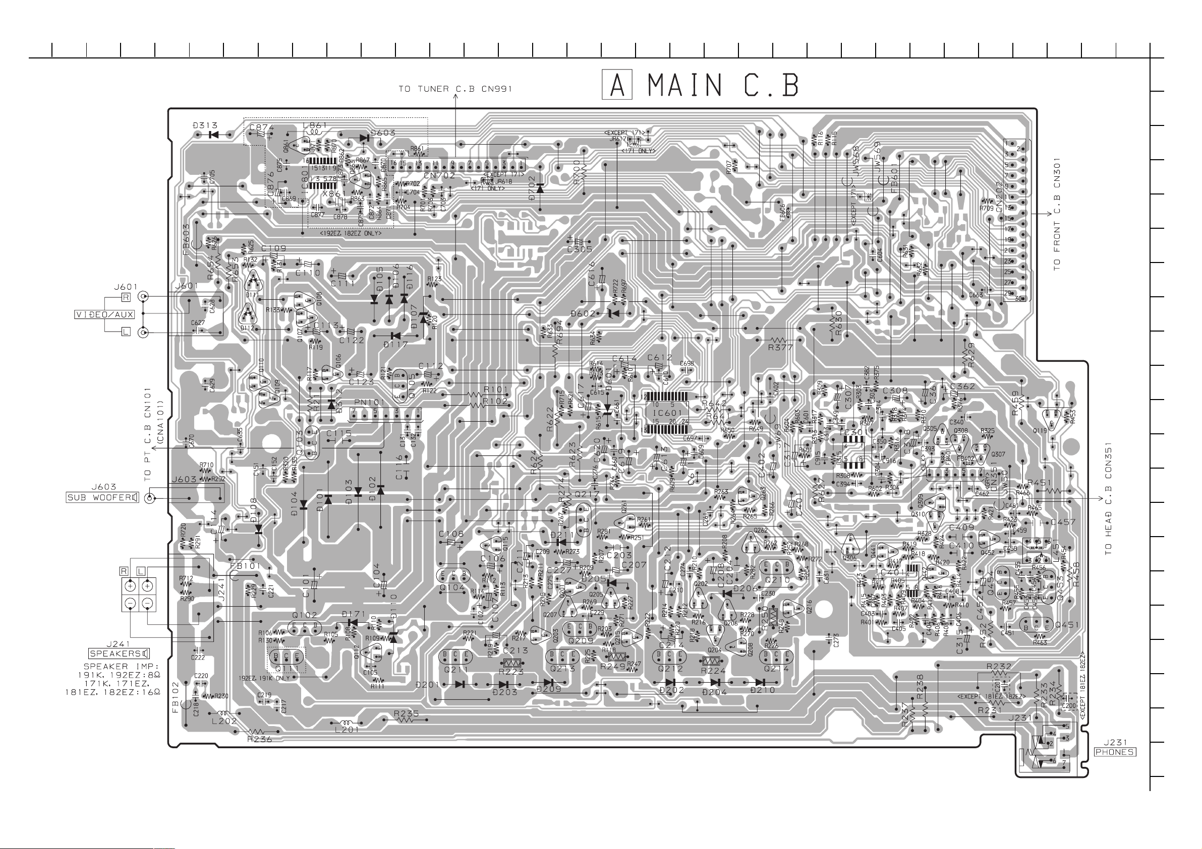
WIRING 1 (MAIN)
32 31 30 29 28 27 26 25 24 23 22 21 20 19 18 17 16 15 14 13 12 11 10 9 8 7 6 5 4 3 2 1
A
B
C
D
E
F
G
H
I
J
K
L
M
N
O
P
Q
7
R
S
T
U
Page 8

SCHEMATIC DIAGRAM – 1 (MAIN)
– 8 –
Page 9

WIRING 2 (TUNER)
151413121110987654321
A
B
C
D
E
F
G
H
I
J
K
L
M
N
O
P
Q
9
R
S
T
U
Page 10

SCHEMATIC DIAGRAM – 2 (TUNER)
– 10 –
Page 11

WIRING – 3 (FRONT)
32 31 30 29 28 27 26 25 24 23 22 21 20 19 18 17 16 15 14 13 12 11 10 9 8 7 6 5 4 3 2 1
A
B
C
D
E
F
G
H
I
J
K
L
M
N
O
P
Q
– 11 –
R
S
T
U
Page 12

SCHEMATIC DIAGRAM – 3 (FRONT / DECK)
– 12 –
Page 13

WIRING – 4 (CD / DRIVE / LOAD)
32 31 30 29 28 27 26 25 24 23 22 21 20 19 18 17 16 15 14 13 12 11 10 9 8 7 6 5 4 3 2 1
A
B
C
D
E
F
G
H
I
J
K
L
M
N
O
P
Q
– 13 –
R
S
T
U
Page 14

SCHEMATIC DIAGRAM – 4 (CD / DRIVE / LOAD)
– 14 –
Page 15

WIRING 5 (PT)
151413121110987654321
A
B
C
D
E
F
G
H
I
J
K
L
M
N
O
P
Q
15
R
S
T
U
Page 16

SCHEMATIC DIAGRAM – 5 (PT)
– 16 –
Page 17

IC BLOCK DIAGRAM
– 17 –
Page 18

ADJUSTMENT <TUNER / DECK>
< TUNER SECTION >
1. Clock Frequency Check
Settings : • Test point : TP2 (CLK)
Method : Set to MW 1602 kHz and check that the test point is
2052 kHz ± 45 Hz.
2. MW VT Check
Settings : • Test point : TP1 (VT)
Method : Set to MW 1602 kHz and check that the test point is
less than 8.0 V. Then set to MW 531 kHz and check
that the test point is more than 0.6 V.
3. LW VT Adjustment
Settings : • Test point : TP1 (VT)
• Adjustment location :L942
Method : Set to LW 144 kHz and adjust L942 so that the test
point becomes 1.3 ± 0.05V. Then set to LW 290 kHz
and check that the test point is less than 8.0 V.
4. MW Tracking Adjustment
Settings : • Test point : TP8 (Rch), TP9 (Lch)
• Adjustment location : L951(1/3)
Method : Set to MW 999 kHz and adjust L951(1/3) so that the
test point becomes maximum.
5. LW Tracking Adjustment
Settings : • Test point : TP8 (Rch), TP9 (Lch)
• Adjustment location :
L941 .................................................... 144kHz
TC942 ................................................. 290kHz
Method : Set up TC942 to center before adjustment. The level
at 144 kHz is adjusted to maximum by L941. Then the
level at 290 kHz is adjusted to maximum by TC942.
6. AM IF Adjustment
Settings : • Test point : TP8 (Rch), TP9 (Lch)
• Adjustment location : L802
L802 ................................................... 450 kHz
7. FM VT Adjustment
Settings : • Test point : TP1 (VT)
• Adjustment location : L907
Method : Set to FM 108.0 MHz and adjust the L907 so that the
test point is 7.00 V ± 0.05 V.
8. FM VT Check
Settings : • Test point : TP1 (VT)
Method : Set to FM 87.5 MHz check that the test point is more
than 0.5 V.
9. FM Tracking Adjustment
Settings : • Test point : TP8 (Rch), TP9 (Lch)
• Adjustment location: L904
Method : Set to FM 108 MHz and adjust L904 so that the test
point becomes maximum and distortion to minmum.
10. FM Tracking Check
Settings : • Test point : TP8 (Rch), TP9 (Lch)
Method : Set to FM 98.0 MHz and check that the test point
is less than 13 dBµV.
11. DC Balance / Mono Distortion Adjustment
Settings : • Test point : TP3, TP4 (DC Balance)
TP8 (Rch), TP9 (Lch)
(Mono Distortion)
• Adjustment location : L801
• Input level : 60 dBµV
Method : Set to FM 98.0 MHz and adjust L801 so that the
voltage between TP3 and TP4 becomes 0 V ± 500 mV
with minimum distortion.
12. Output Level Check
<MW>
Settings : • Test point : TP8 (Rch), TP9 (Lch)
• Input level : 74 dBµV
Method : Set to MW 999 kHz and check that the test point is
55 mV ± 3 dB.
<FM>
Settings : • Test point : TP8 (Rch), TP9 (Lch)
• Input level : 60 dBµV
Method : Set to FM 98.0 MHz and check that the test point is
270 mV ± 3 dB.
13. FM Separation Check
Settings : • Test point : TP8 (Rch), TP9 (Lch)
• Input level : 60 dBµV
Method : Set to FM 98.0 MHz and check that the separation
at the test point is more than 25 dB.
< DECK SECTION >
1. Tape Speed Check
Settings : • Test tape : TTA–100
• Test point : SP OUT
Method : Play back the test tape FWD / REV and
check the difference speed is ± 45 Hz.
2. Head Azimuth Adjustment
Settings : • Test tape : TTA–330
• Test point : SP OUT
• Adjustment location : Head azimuth
adjustment screw
Method : Play back FWD the 8 kHz signal of the test tape and
adjust screw so that the output becomes maximum.
Next, perform on REV PLAY mode.
3. PB Frequency Response Check
Settings : • Test tape : TTA–320
• Test point : SP OUT
Method : Play back the 315 Hz and 10 kHz signals of the test
tape and check that the 10 kHz signal with respect to
that of the 315 Hz signal is -3 dB ± 3 dB.
4. REC/PB Frequency Response Check
Settings : • Test tape : TTA–602
• Test point : SP OUT
• Input signal : 8 kHz /1 kHz (-20 VU / 0 dB)
Method : Input a -20 VU signal to the VIDEO/AUX terminal.
Record the 1 kHz and 8 kHz signals on the test tape
and play back them. Check that the difference between
the record level and the play back level at 1 kHz and
8 kHz signal is -2 dB ± 3 dB.
– 18 –
Page 19

MECHANICAL EXPLODED VIEW 1 / 1
– 19 –
Page 20

MECHANICAL PARTS LIST 1 / 1
REF. NO. DESCRIPTIONPART NO. KANRI
1 88-CL4-215-010 CUSH,FOOT FR
2 8B-CL9-048-010 BOX,CASS M191 MS<191K>
2 8B-CL9-047-010 BOX,CASS M192 MS<192EZ>
2 8B-CLK-047-010 BOX,CASS M181 B202<181EZ>
2 8B-CLK-046-010 BOX,CASS M182 B202<182EZ>
2 8B-CLW-048-010 BOX,CASS M172 B202<171EZ,171K>
3 8B-CL9-054-010 WINDOW,CASS SK
4 8B-CL9-080-010 KNOB,RTRY VOLUME
5 8B-CL9-077-010 RING,VOLUME
6 8B-CL9-053-010 WINDOW,DISP RDS SK<192EZ,182EZ>
6 8B-CL9-055-010 WINDOW,DISP SK<191K,171EZ,171K,181EZ>
7 8B-CL9-034-010 WINDOW,CD SK
8 8B-CL9-033-010 PANEL,CD MS<191K,192EZ>
8 8B-CLK-031-010 PANEL,CD B202<181EZ,182EZ,171EZ,171K>
9 8A-MA6-203-010 PLATE,FL
10 82-NF7-210-010 GUIDE,FL(*)
11 8B-CL9-060-010 KEY ASSY,POWER
12 8B-CL9-088-010 LENS,REMOTE-C
13 8B-CL9-064-010 KEY,DEMO
14 8B-CL9-065-010 KEY,CONTROL
15 8B-CL9-201-010 GUIDE,FUNC
16 8B-CL9-069-010 KEY ASSY,FUNC SK
17 8B-CL9-076-010 RING,FUNC
18 8B-CL9-062-010 KEY,OPEN
19 8B-CL9-063-010 KEY,Q-SOUND
20 82-NF5-229-010 PLATE,LOCK
21 86-NF9-224-010 SPR-C,LOCK
22 87-NF4-217-110 HLDR,LOCK 2
23 88-CL4-220-010 SPR-T,CASS
24 87-NF8-220-010 DMPR,150
25 8B-CL9-003-010 CABI,FRONT MS<191K>
25 8B-CL9-002-010 CABI,FRONT RDS MS<192EZ>
25 8B-CLK-002-010 CABI,FRONT B202<181EZ,171EZ,171K>
25 8B-CLK-003-010 CABI,FRONT RDS B202<182EZ>
26 8B-CL9-204-010 HLDR,CD
27 8B-CL9-026-010 CABI,TOP
!
28 87-A80-143-010 AC CORD ASSY,E BLK<191K,171K>
28 87-A80-092-010 AC CORD ASSY,E BLK SUN FAI<192EZ,181EZ,182EZ,171EZ>
!
29 8B-CL9-014-010 PANEL,REAR EZSC<191K,192EZ>
29 8B-CLK-011-010 PANEL,REAR EZSC<181EZ,182EZ,171EZ,171K>
30 8A-CL9-211-110 HLDR,TRANS
31 88-CL4-216-010 CUSH,FOOT REAR
32 82-ZM1-264-010 LVR,EJECT R
33 87-A90-562-010 F-BEAD,9.5-17.5-28.5 BRH
A 87-067-703-010 TAPPING SCREW, BVT2+3-10
B 87-581-170-410 UIT+4-8<191K,192EZ>
C 87-B10-231-010 QT1+3-12 SILVER CR
D 87-B10-230-010 BVT2+3-10 W/O SLOT SILVER CR
E 87-B10-250-010 BVT2+3-12 W/O SLOT CR SILVER
KANRI
NO.
REF. NO. DESCRIPTIONPART NO.
NO.
COLOR NAME TABLE
Basic color symbol Color Basic color symbol Color Basic color symbol Color
B Black C Cream D Orange
G Green H Gray L Blue
LT Transparent Blue N Gold P Pink
R Red S Silver ST Titan Silver
T Brown V Violet W White
WT Transparent White Y Yellow YT Transparent Yellow
LM Metallic Blue LL Light Blue GT Transparent Green
LD Dark Blue DT Transparent Orange GM Metallic Green
YM Metallic Yellow DM Metallic Orange PT Transparent Pink
LA Aqua Blue GL Light Green HT Transparent Gray
– 20 –
Page 21

SPEAKER PARTS LIST (SX-LM181 <YJMN>)
REF. NO. DESCRIPTIONPART NO. KANRI
1 8B-CPK-002-010 GRILLE,FRAME ASSY
2 8B-CPW-602-010 SPKR,110 160HMS
3 8A-CL9-163-010 SPKR,CERAMIC
4 8A-CL9-164-010 CORD, SP
KANRI
NO.
REF. NO. DESCRIPTIONPART NO.
NO.
SPEAKER PARTS LIST (SX-LM192 <YJMN>)
REF. NO. DESCRIPTIONPART NO.
1 8B-CP9-002-010 PANEL,FR
2 8B-CP9-011-010 PANEL,TW
3 8B-CP9-012-010 RING,TW G
4 8B-CP9-013-010 GRILLE,FRAME ASSY D/G
5 8A-CL9-164-010 CORD, SP
6 8A-CL9-163-010 SPKR,CERAMIC
KANRI
NO.
SPEAKER PARTS LIST (SX-LM172 <YJSN>)
REF. NO. PART NO.
1 8B-CPW-001-010 CABI,FR
2 8B-CPW-002-010 CABI,REAR
3 8B-CPW-008-010 GRILLE,FRAME ASSY D/L
4 8A-CL9-164-010 CORD, SP
5 8A-CL9-163-010 SPKR, CERAMIC
6 8B-CPW-602-010 SPKR, 110 160HMS
KANRI
NO.
DESCRIPTION
– 21 –
Page 22

2–11, IKENOHATA 1–CHOME, TAITO-KU, TOKYO 110, JAPAN TEL:03 (3827) 3111
Printed in Singapore9820572 2000044 9630472
 Loading...