

Page 1
AIWA VX-T1480
Recommended Safety Parts
Item Part No. Description
M101 S5-96P-480-010 MOTOR, LOAD(1) 1
M2001 S5-94J-980-040 CAPSTAN DD UNIT SP39BD 1
M2003 S5-89V-110-040 MICRO MOTOR EP14BA 1
R1042 87-029-165-060 RES, FUSE 2.7 - 1W
UN4001 S4-841-1B5-000 CYLINDER UNIT ASS’Y 1
IC1002 S0-7S0-902-9A0 JC, OEC9029A
TU6001 S1-447-070-200 TUNER UHF UE25-B01
R445 87-022-304-010 RES, M/O 1.5K - 3W
R446 87-022-304-010 RES, M/O 1.5K - 3W
R447 56-158-268-0J0 RES, FUSE 68 - 1/2W
R449 S5-K2C-E8R-2K0 RES, CEM 8.2 - 7W
R450 87-029-160-010 RES, FUSE 2.2 - 1W
R452 S6-358-11R-8J0 RES, FUSE 1.8 - 1W
R501 S5-K20-E2R-2K0 RES, CEM 2.2 - 7W
R505 S3-X28-B33-3J0 R, M/O 33K - 3W
R508 S3-X28-D47-3J0 RES, M/O 47K - 5W
R512 S3-U18-182-2J0 RES, M/O 8.2K - 1W
R513 87-022-623-010 RES, M/O 15 - 2W
R517 S6-148-12R-2J0 RES, FUSE 22 - 1W
R531 S3-X18-AR5-6J0 RES, M/O 0.56 OHM
R538 S0-11K-215-5J0 RES, 1.5M - 1/2W
R598 87-029-374-010 RES, FUSE 47 - 1/4W
C502 S0-JBB-07H-3K0 CAP, CER 0.0022 - 2KV
C503 S0-JBB-07H-3K0 CAP, CER 0.0022 - 2KV
C505 S2-222-B22-4K0 CMP, 0.22 - 250V
C506 S2-222-B10-4K0 CMP, 0.1 - 250V
C515 S0-E7T-B01-0M0 CAP, E 1-160V
C529 SB-393-0MH-3M0 CAP, CER 0.0022 - 250V
C530 SB-393-0MQ-2K0 CAP, CER 470PF - 250V
C533 SB-393-0M1-2K0 CAP, CER 100PF - 250V
C546 SB-393-0MH-3M0 CAP, CER 0.0022 - 250V
D411 S2-8T1-0EL-S60 DIODE, 10ELS6TA1
D501 S2-BTR-M11-C00 DIODE, RM11C
D502 S2-BTR-M11-C00 DIODE, RM11C
D503 S2-BTR-M11-C00 DIODE, RM11C
D504 S2-BTR-M11-C00 DIODE, RM11C
D508 S2-8TE-QS0-400 DIODE, 11EQS04TA1
D509 S2-8T1-0EL-S60 DIODE, 10ELS6TA1
D510 S2-811-5DF-600 DIODE,1SDF6-FC
D512 S2-8T1-DQ0-900 DIODE, 21DQ09-TA2B1
D519 S2-8T1-DQ0-900 DIODE, 21DQ09-TA2B1
IC401 S0-5SD-840-300 IC, TA8403K
IC501 S0-ED0-460-500 lC, TDA4605-3
IC502 S0-Q09-780-500 IC, NJM7805FD
IC506 S0-025-004-500 PHOTO, COUPLER TLP621 (GR)
Q406 SD-UQ0-208-900 TR, 2SD2089
Q500 S4-1FK-239-700 TR, 2SK2397 - 01
Q502 SA-3T1-371-A00 TR, 2SA1371
Q503 SC-300-416-000 TR, 2SC4160
Q511 SB-WT0-092-600 TR, 2SB926 (S,T)
Q516 SD-70D-239-600 TR, 2SD2396
L501 S2-9K0-000-010 COIL, LINE FILTER RB-20871
L502 S2-9K0-000-010 COIL, LINE FILTER RB-20871
FB401 S4-321-300-9F0 TR, 3213009
T501 S4-813-502-2W0 TR, 8135022W
F501 S8-0PT-040-020 FUSE, 4A-250V T
F502 S8-0PT-1R6-020 FUSE, 21801.6
RY501 S5-600-101-140 RELAY SDT-SS-109DM
ICP502 S8-3PC-030-020 MICRO FUSE, 251003
ICP503 S8-3PC-050-020 MICRO FUSE, 251005
ICP504 S8-3PC-030-020 MICRO FUSE, 251003
ICP505 S8-3PC-010-020 MICRO FUSE, 251001
R802 87-A00-164-060 R, M/O 12K - 2W
R805 87-A00-164-060 R, M/O 12K - 2W
R810 87-A00-164-060 R, M/O 12K - 2W
Q804 89-314-736-080 TR, 2SC1473A - TA
Q805 89-314-736-080 TR, 2SC1473A - TA
Q806 89-314-736-080 TR, 2SC1473A-TA
J801 S6-6X1-200-140 SOCKET, CRT HPS320
SW501 S5-302-050-010 SW, PLUSSDDFC3O56A
L503 S2-8Q1-400-180 COIL, DEGAUSS 8Q140018
CD501 S2-066-358-070 CORD, AC 1206635807
V801 S9-8Y1-404-640 CRT, W/DY14” A34JXV70X06N
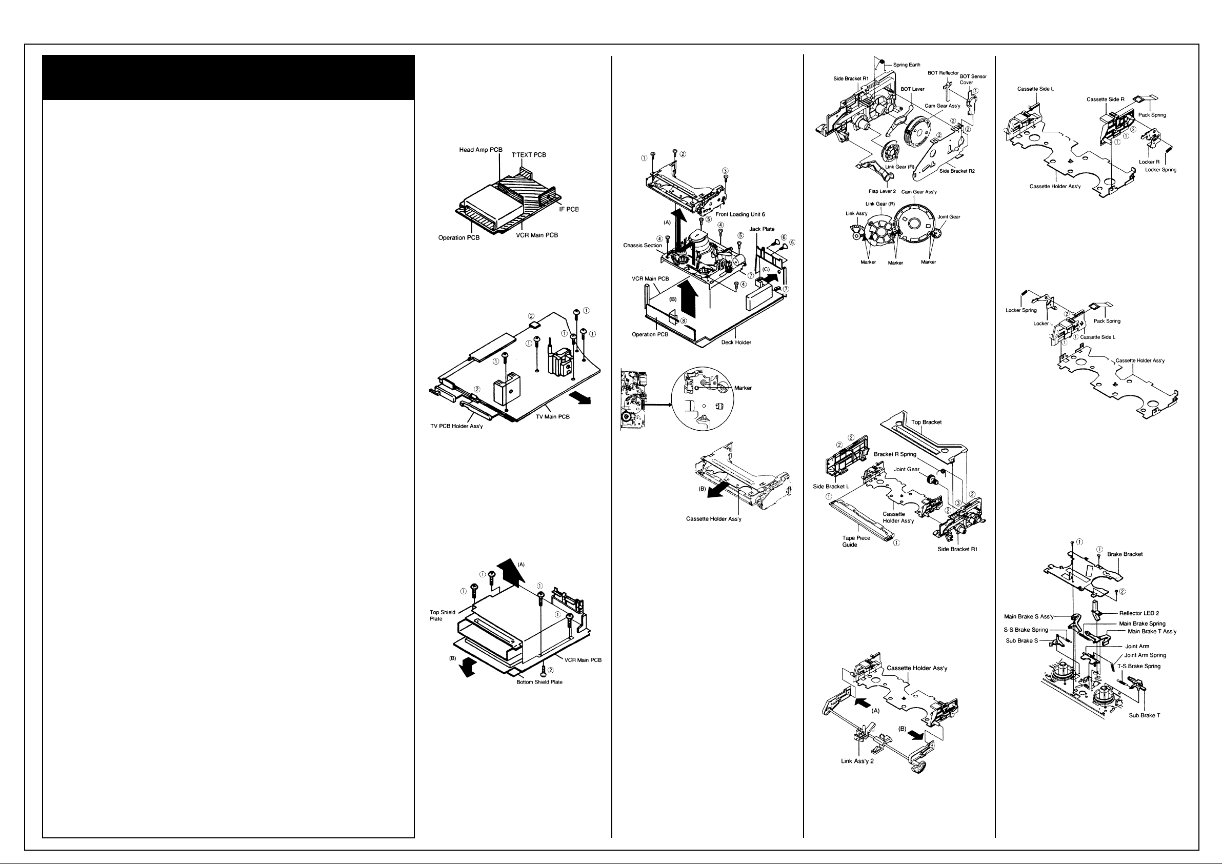
Disassembly Instructions
1-4: LOCATION OF PRINTED CIRCUIT
BOARDS
(Refer to Fig. 1-4)
CAUTION: BEFORE ATTEMPTING TO
REMOVE OR REPAIR ANY PCB, UNPLUG
THE POWER CORD FROM THE AC SOURCE.
Fig. 1-4
1-5: MAIN PCB (Refer to Fig. 1-5)
1. Remove the 5 screws (1).
2. Unlock the 2 supports (2) and remove the TV
Main PCB in the direction of the arrow.
Fig. 1-5
1-6: TOP SHIELD PLATE AND BOTTOM
SHIELD PLATE
(Refer to Fig. 1-6)
1. Remove the 4 screws (1).
2. Remove the Top Shield Plate in the direction
of arrow (A).
3. Remove the screw (2).
4. Remove the Bottom Shield Plate in the
direction of arrow (B).
Fig. 1-6
1-7: FRONT LOADING UNIT 6, CHASSIS
SECTION, JACK PLATE AND VCR MAIN PCB
(Refer to Fig. 1-7-A)
1. Remove the screw (1).
2. Remove the screw (2).
3. Remove the screw (3).
4. Remove the Front Loading Unit 6 in the
direction of arrow (A).
5. Remove the 3 screws (4).
6. Remove the 2 screws (5).
7. Remove the Chassis Section in the direction
of arrow (B).
8. Remove the 2 screws (6).
9. Unlock the 2 supports (7) and remove the
Jack Plate in the direction of arrow (C).
10.Unlock the support (8) and remove the VCR
Main PCB.
NOTE
When installing the Front Loading Unit 6, align
the timing marks and pull the Cassette Holder
Ass’y in the direction of arrow (D). (Refer to Fig.
1-7-B)
Fig. 1-7-A
Fig. 1-7-B
2. REMOVAL OF DECK PARTS
2-1: LINK GEAR (R) / CAM GEAR (Refer to
Fig. 2-1)
1. Unlock the support (1).
2. Remove the BOT Sensor Cover and BOT
Reflector.
3. Unlock the 3 supports (2).
4. Remove the Side Bracket R2 and Spring
Earth.
5. Remove the Flap Lever, Link Gear (R), Cam
Gear Ass’y and BOT Lever.
NOTES
When installing the Link Ass’y 2 and Link Gear
(R), align the timing Marks.
Fig. 2-1
2-2: TOP BRACKET / TAPE PIECE GUIDE
(Refer to Fig. 2-2)
1. Unlock the 2 supports (1).
2. Remove the Tape Piece Guide.
3. Unlock the 4 supports (2).
4. Remove the Top Bracket.
5. Remove the Side Bracket R1 and Side
Bracket L.
6. Unlock the support (3).
7. Remove the Joint Gear.
8. Remove the Bracket R Spring.
Fig. 2-2
2-3: LINK ASS’Y 2 (Refer to Fig. 2-3)
1. After removing in the direction (A) of Link
Ass’y 2, remove the Link Ass’y 2 in the
direction (B).
NOTE
Install the (B) first, then install the (A).
Fig. 2-3
2-4: CASSETTE SIDE R (Refer to Fig. 2-4)
1. Unlock the 2 supports (1).
2. Remove the Cassette Side R.
3. Remove the Pack Spring.
4. Remove the Locker Spring.
5. Unlock support (2).
6. Remove the Locker R.
Fig. 2-4
2-5: CASSETTE SIDE L (Refer to Fig. 2-5)
1. Unlock the 2 supports (1).
2. Remove the Cassette Side L.
3. Remove the Pack Spring.
4. Remove the Locker Spring.
5. Unlock the support (2).
6. Remove the Locker L.
Fig. 2-5
2-6: BRAKE BRACKET (Refer to Fig. 2-6)
1. Remove the Main Brake Spring, S-S Brake
Spring, Joint Arm Spring and T-S Brake
Spring.
2. Remove the 2 screws (1).
3. Remove the screw (2).
4. Remove the Brake Bracket.
5. Remove the Sub Brake S, Sub Brake T, Main
Brake S Ass’y and Main Brake T Ass’y.
6. Remove the Joint Arm.
7. Remove the Reflector LED 2.
Fig. 2-6
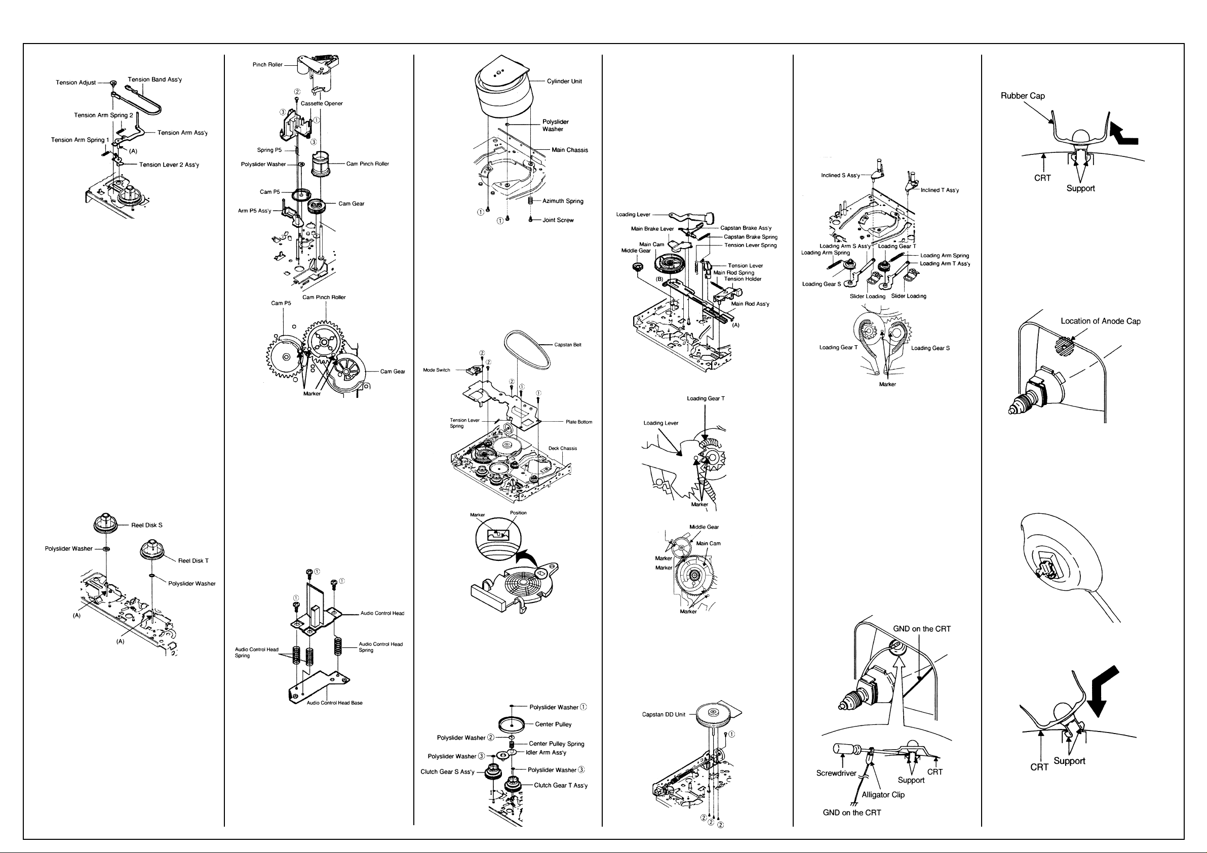
2-7: TENSION BAND (Refer to Fig. 2-7)
1. Remove the Tension Arm Spring 1.
2. Remove the Tension Arm Spring 2.
3. Remove the Tension Adjust.
4. Remove the Tension Arm Ass’y.
5. Remove the Tension Band Ass’y.
6. Remove the Tension Lever 2 Ass’y.
Continues on next page.
Page 2
AIWA VX-T1480
Disassembly Cont’d
Fig. 2-7
NOTES
1. Install the Tension Band Ass’y without twisting it.
2. Oil the area marked with A in Fig. 2-7.
2-8: REEL DISK (Refer to Fig. 2-8)
1. Remove the Reel Disk S and Reel Disk T.
2. Remove the 2 polyslider washers.
NOTES
1. Installation of Reel Disk after performing step
1, 2 and 3 in section 2-7 of DISASSEMBLY
INSTRUCTIONS.
2. The Height Adjustment washers are sometimes attached to the back of the Reel Disk.
3. Clean the Reel Disk Shaft and put in height
adjusting washers.
4. Be careful not to damage the Tension Band
Ass’y at the time of removal and installation.
5. Be careful not to scratch the Reel Disk Shaft
with the polyslider washer or the tool at the
time of removal and installation.
6. After oiling the Reel Disk Shaft, install the
new Reel Disk S and Reel Disk T again.
7. After installation, adjust the height of the Reel
Disk. (Refer to item 1-1 of MECHANICAL
ADJUSTMENTS)
8. After installation, adjust and confirm the
tension post position. (Refer to item 1-2 of
MECHANICAL ADJUSTMENTS)
Fig. 2-8
2-9: PINCH ROLLER / CASSETTE OPENER
(Refer to Fig. 2-9)
1. Unlock the support (1).
2. Remove the Pinch Roller.
3. Remove the screw (2).
4. Unlock the 2 supports (3).
5. Remove the Cassette Opener.
6. Remove the Spring P5 and Arm P5 Ass’y.
7. Remove the Cam Gear, Polyslider Washer 4,
Spring Cam Pinch and Cam Pinch Roller.
8. Remove the Polyslider Washer 5 and Cam
P5.
NOTES
1. Do not touch the Pinch Roller. (Use gloves.)
2. When installing the Cam P5, Cam Pinch
Roller and Cam Gear, align the timing marks.
Fig. 2-9
2-10: AUDIO CONTROL HEAD
(Refer to Fig. 2-10)
1. Disconnect the following connector: (CP4106
6 pins) on the Head Amp PCB.
2. Remove the 3 screws (1).
3. Remove the 3 Audio Control Head Springs.
4. Remove the Audio Control Head.
NOTES
1. Do not touch the head by any means when
replacing the Audio Control Head. (Use
gloves.)
2. After replacement, confirm the following
adjustments.
a. MECHANICAL ADJUSTMENTS: ITEM 2-2
b. MECHANICAL ADJUSTMENTS: ITEM 2-3
Fig. 2-10
2-11: CYLINDER UNIT (Refer to Fig. 2-11)
1. Disconnect the following connectors:
(CP4101 4 pins and CP4102 5 pins) on the
Head Amp PCB.
2. Remove the Joint Screw, then remove the
Azimuth Spring.
3. Remove the 2 screws (1), then remove the
Polyslider Washer and Cylinder Unit from the
Main Chassis.
Fig. 2-11
2-12: PLATE BOTTOM (Refer to Fig. 2-12)
1. Remove the Capstan Belt.
2. Remove the 2 screws (1).
3. Remove the 3 screws (2).
4. Remove the Mode Switch.
5. Remove the Tension Lever Spring.
6. Remove the Plate Bottom.
NOTE
When installing the Mode Switch, align the
timing position.
Fig. 2-12
2-13: CENTER PULLEY (Refer to Fig. 2-13)
1. Remove the Polyslider Washer (1).
2. Remove the Center Pulley.
3. Remove the Polyslider Washer (2).
4. Remove the Center Pulley Spring.
5. Remove the Idler Arm Ass’y.
6. Remove the 2 Polyslider Washers (3).
7. Remove the Clutch Gear T Ass’y and Clutch
Gear S Ass’y.
Fig. 2-13
2-14: MAIN CAM (Refer to Fig. 2-14)
1. Remove the Loading Lever.
2. Remove the Main Brake Lever.
3. Remove the Capstan Brake Spring.
4. Remove the Capstan Brake Ass’y.
5. Remove the Main Rod Spring.
6. Remove the Tension Holder.
7. Remove the Tension Lever.
8. Remove the Main Cam.
9. Remove the Middle Gear.
10. Remove the Main Rod Ass’y.
NOTES
1. When installing the Main Rod Ass’y, install
side (B) first, then install side (A).
2. When installing the Loading Lever, align the
timing marks.
Fig. 2-14
2-15: CAPSTAN DD UNIT (Refer to Fig. 2-15)
1. Remove the screw (1)
2. Disconnect the CP4105 9 pins.
3. Remove the 3 screws (2).
4. Remove the Capstan DD Unit.
NOTE
Use the specified screw to hold the Capstan DD
Unit.
Fig. 2-15
2-16: INCLINED T ASS’Y / INCLINED S ASS’Y
(Refer to Fig. 2-16)
1. Remove the 2 Slider Loadings.
2. Remove the Inclined T Ass’y and Inclined S
Ass’y.
3. Remove the Loading Gear T Ass’y.
4. Remove the Loading Gear S Ass’y.
NOTE
When installing the Inclined T Ass’y and Inclined
S Ass’y, align the timing marks.
Fig. 2-16
3. REMOVAL OF ANODE CAP
Read the following NOTED items before starting
work.
* After turning the power off there might still be a
potential voltage that is very dangerous. When
removing the Anode Cap, make sure to discharge the Anode Cap’s potential voltage.
* Do not use pliers to loosen or tighten the
Anode Cap terminal, this may cause the spring
to be damaged.
REMOVAL
1. Follow the steps as follows to discharge the
Anode Cap. (Refer to Fig. 3-1.) Connect one
end of an Alligator Clip to the metal part of a
flat-blade screwdriver and the other end to
ground. While holding the plastic part of the
insulated Screwdriver, touch the support of
the Anode with the tip of the Screwdriver. A
cracking noise will be heard as the voltage is
discharged.
Fig. 3-1
2. Flip up the sides of the Rubber Cap in the
direction of the arrow and remove one side of
the support. (Refer to Fig. 3-2.)
Fig. 3-2
3. After one side is removed, pull in the opposite
direction to remove the other.
NOTE
Take care not to damage the Rubber Cap.
INSTALLATION
1. Clean the spot where the cap was located
with a small amount of alcohol. (Refer to Fig.
3-3.)
Fig. 3-3
NOTE
Confirm that there is no dirt, dust, etc. at the
spot where the cap was located.
2. Arrange the wire of the Anode Cap and make
sure the wire is not twisted.
3. Turn over the Rubber Cap. (Refer to Fig. 3-4.)
Fig. 3-4
4. Insert one end of the Anode Support into the
anode button, then the other as shown in Fig.
3-5.
Fig. 3-5
5. Confirm that the Support is securely connected.
6. Put on the Rubber Cap without moving any
parts.
Page 3
AIWA VX-T1480
Mechanical Adjustments
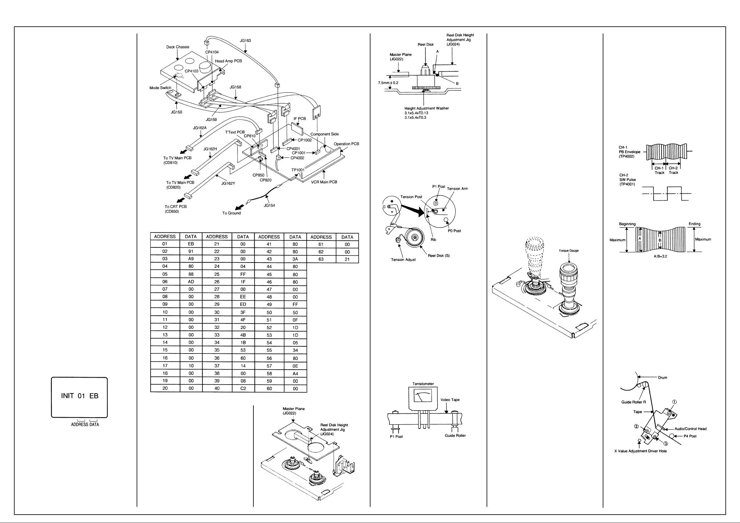
SERVICING PREPARATION
How to use the servicing fixture
1. Remove the VCR Main PCB from the Deck
Chassis.
2. Connect as shown in the figure using the
Service Fixture.
• Connect the VCR Main PCB to the Mode
Switch with the cable JG150.
• Connect the VCR Main PCB to the Head Amp
PCB with the cable JG158 and JG159.
• Connect the VCR Main PCB to the TV Main
PCB with the cable JG162A and JG 162H.
• Connect the VCR Main PCB to the CRT PCB
with the cable JG162Y.
• Connect the VCR Main PCB to the FE Head
with the cable JG163.
3. Short circuit between TP1001 and Ground
with the cable JG154. (Refer to MAJOR
COMPONENTS LOCATION GUIDE)
4. The EOT, BOT and Reel Sensor do not work
at this moment.
5. At that time, the STOP/EJECT button is
available to insert and eject the Cassette
Tape.
INSTRUCTIONS
1. Unplug the AC cord once and the clock will be
non-setting.
2. Turn on the POWER and set the VOLUME to
minimum.
NOTE:
If the Auto Set Up Function is working, the unit
cannot be operated. In this case, release the
Function or wait until the Function goes to the
end.
3. Press the VOL. DOWN button on the set and
the Channel button (6) on the remote control
simultaneously. The Fig. 1 appears on the
display.
4. Press the SET +/- button on the remote
control to modify the address and check the
data.
(Refer to Table 1)
5. After checking, turn off the Power.
(If the wrong data is input)
6. Press the SET +/- button on the remote
control to set to the address of the wrong
data, then press the ENTER button. The data
will bink. (Refer to Fig. 1)
7. Press the SET +/- button on the remote
control to set to the correct data, then press
the ENTER button. (Refer to Table 1)
8. Repeat the above steps 6 and 7 and input the
data into the each Address.
9. After the data input, turn off the Power.
Fig. 1
1. CONFIRMATION AND ADJUSTMENT
Read the following NOTED items before starting
work.
• Place an object which weighs between 350g
and 500g on the Cassette Tape to keep it
steady when you want to make the tape run
without the Front Loading Unit 6. (Do not
place an object which weighs over 500g.)
Reel Disk (S)
• When you activate the deck without the Front
Loading Unit 6, short circuit between TP1001
and Ground. In this condition the BOT/EOT/
Reel Sensor will not function.
1-1: CONFIRMATION AND ADJUSTMENT OF
REEL DISK HEIGHT
1. Turn on the power and set to the STOP
mode.
2. Set the master plane (JG022) and reel disk
height adjustment jig (JG024) on mechanism
framework, taking care not to scratch the
drum, as shown in Fig. 1-1-A.
3. Confirm that the reel disk is lower than “A” of
the reel disk height adjustment jig (JG024) on
the master plane and higher than “B” as
shown in Fig. 1-1-B. If it is not, adjust to less
than 7.5mm±0.2mm with the height adjustment washer.
4. Perform the same adjustment for other reel.
Fig. 1-1-A
Fig. 1-1-B
1-2: CONFIRMATION AND ADJUSTMENT OF
TENSION POST POSITION
1. Turn on the power and set to the PLAY mode
adjust the Tension so that the Tension Post is
at the position of 0.3mm~0.5mm from the Rib.
(Refer to Fig. 1-2)
2. Confirm that the video tape is not curling at
the flange of P1 post or is not running on
flanges.
Fig. 1-2
1-3: CONFIRMATION AND ADJUSTMENT OF
BACK TENSION ON PLAYBACK
1. Load a video tape recorded in standard speed
mode. Set the unit to the PLAY mode.
2. Install the tentelometer as shown in Fig. 1-3.
Confirm the value is within 20~27gr/cm at this
time.
IN CASE OF USING A CASSETTE TYPE
TORQUE TAPE.
1. After adjustment, confirm and adjust the
tension post position (Refer to item 1-2) for
the tension arm, install the cassette type
torque tape (JG100A) and set to the PLAY
mode.
2. Confirm that the left hand side tension value
of the torque tape is 25~38gr/cm for the
standard mode tape.
Fig. 1-3
1-4: CONFIRMATION OF FAST FORWARD
TORQUE
1. Set torque gauge (JG002G) on take-up reel
disk, and place unit in FAST FORWARD
mode. (Refer to Fig. 1-4)
2. Confirm that torque is more than 400gr/cm.
NOTE
After setting the torque gauge on the reel disk,
hold the gauge in place. Push the FAST
FORWARD button and the reel disk will begin to
turn.
1-5: CONFIRMATION OF REWIND TORQUE
1. Operate within 4 or 5 seconds after the reel
disk begins to turn.
2. Set torque gauge (JG002G) on supply reel
disk, and place the unit in REWIND mode.
(Refer to Fig 1-4).
3. Confirm that torque is more than 400gr/cm.
NOTE
After setting the torque gauge on the reel disk,
hold the gauge in place.
Push the REWIND button and the reel disk will
begin to turn.
1-6: CONFIRMATION OF REEL BRAKE
TORQUE
(Take-Up Reel Brake) (Refer to Fig. 1-4)
1. Set to STOP mode.
2. Set the torque gauge (JG002G) to the takeup reel and turn it counterclockwise.
3. Confirm that it is more than 200gr/cm at that
time.
(Supply Reel Brake) (Refer to Fig. 1-4)
1. Set to STOP mode.
2. Set the torque gauge (JG002G) to the supply
reel and turn it clockwise.
3. Confirm that it is more than 200gr/cm at that
time.
NOTE
Separate the idler from the reel and confirm the
brake torque.
Fig. 1-4
2-1: GUIDE ROLLER
NOTE
If the torque value checked is out of tolerance,
replace the appropriate parts as follows.
Check Items Replace Parts
1-4 Idler Ass’y or Clutch Ass’y
1-5 Idler Ass’y or Clutch Ass’y
1-6 Main Brake T Ass’y or Main Brake S Ass’y
2. TAPE RUNNING CONFIRMATION AND
ADJUSTMENT
Tape running is adjusted precisely at the factory.
Normally, it is not necessary to make adjustments. It is necessary to confirm and make
adjustments when the parts of the tape running
mechanism are replaced because of extensive
usage or failure.
2-1: GUIDE ROLLER
1. Connect CH-1 on the oscilloscope to TP4002
(PB Envelope) and CH-2 to TP4001 (SW
Pulse).
2. Set the tracking to manual center position in
the following way. Press and hold the tracking
auto button more than 2 seconds to set the
tracking to center position.
3. Trigger with SW pulse and observe the
envelope. (Refer to Fig. 2-1-A)
4. Adjust the guide roller height while observing
the envelope, and make the envelope flat.
Adjust the envelope so that the flatness will
not be affected even when the tracking control
button is pressed. (Use the adjustment
screwdriver JG005).
5. Press and hold the tracking control button
and (at the point that the envelope waveform
starts to reduce) adjust the envelope so that
the A:B ratio is better than 3:2. (Refer to Fig.
2-1-B)
6. Adjust the PG shifter (ELECTRICAL ADJUSTMENTS : ITEM 3-1) in the PLAY mode.
NOTE
After adjustment, confirm and adjust A/C head
tilt. (Refer to item 2-2)
Fig. 2-1-A
Fig. 2-1-B
2-2: CONFIRMATION AND ADJUSTMENT OF
A/C HEAD TILT
When the tape is running abnormally, perform
the following adjustments.
1. Insert a new tape and play it back.
2. Confirm that there is no crease on the tape
between the P4 post and guide roller (R) and
the tape is running smoothly. (It is absolutely
impossible to get satisfactory sound if the
tape is distorted between the A/C head and
P4 post.)
3. If the tape still does not run smoothly, turn the
screw (1) and adjust the tilt of the A/C head.
(Refer to Fig. 2-2)
Fig. 2-2
2-3: ADJUSTMENT OF A/C HEAD HEIGHT
AND AZIMUTH
1. Playback a VHS alignment tape (JG001C)
and observe the waveform at the audio output
terminal.
2. Turn the screw (2) slowly to change the
Page 4
AIWA VX-T1480
Adjustments Cont’d
azimuth of the A/C head. Adjust the height so
that the audio output becomes maximum.
(Refer to Fig. 2-2)
3. Adjust the screw 3, (Refer to Fig. 2-2) until the
height of the A/C head reaches the position
against the tape as shown in Fig. 2-3.
4. When the control head height is not correct.
(When you must turn the screw more than 45
degrees), Turn all of the screws (1), (2) and
(3) to the same degrees. Then confirm the
angle of the audio/control head and adjust
again.
Fig. 2-3
2-4: TAPE RUNNING ADJUSTMENT
1.Adjust the height of reel disk.
(Refer to item 1-1)
2.Confirm and adjust tension post position.
(Refer to item 1-2)
3.Adjust the guide roller.
(Refer to item 2-1)
4.Adjust the A/C head tilt.
(Refer to item 2-2)
5.Adjust the A/C head height and azimuth.
(Refer to item 2-3)
6.Connect CH-1 on the oscilloscope to TP4001
and CH-2 to TP4002. Playback the VHS
alignment tape (JG001E).
Set the tracking to manual center. Adjust X with
the screwdriver for X (JG153) as the Fig. 2-1-A
and Fig. 2-1-B.
(Refer to No. 2 of the item 2-1).
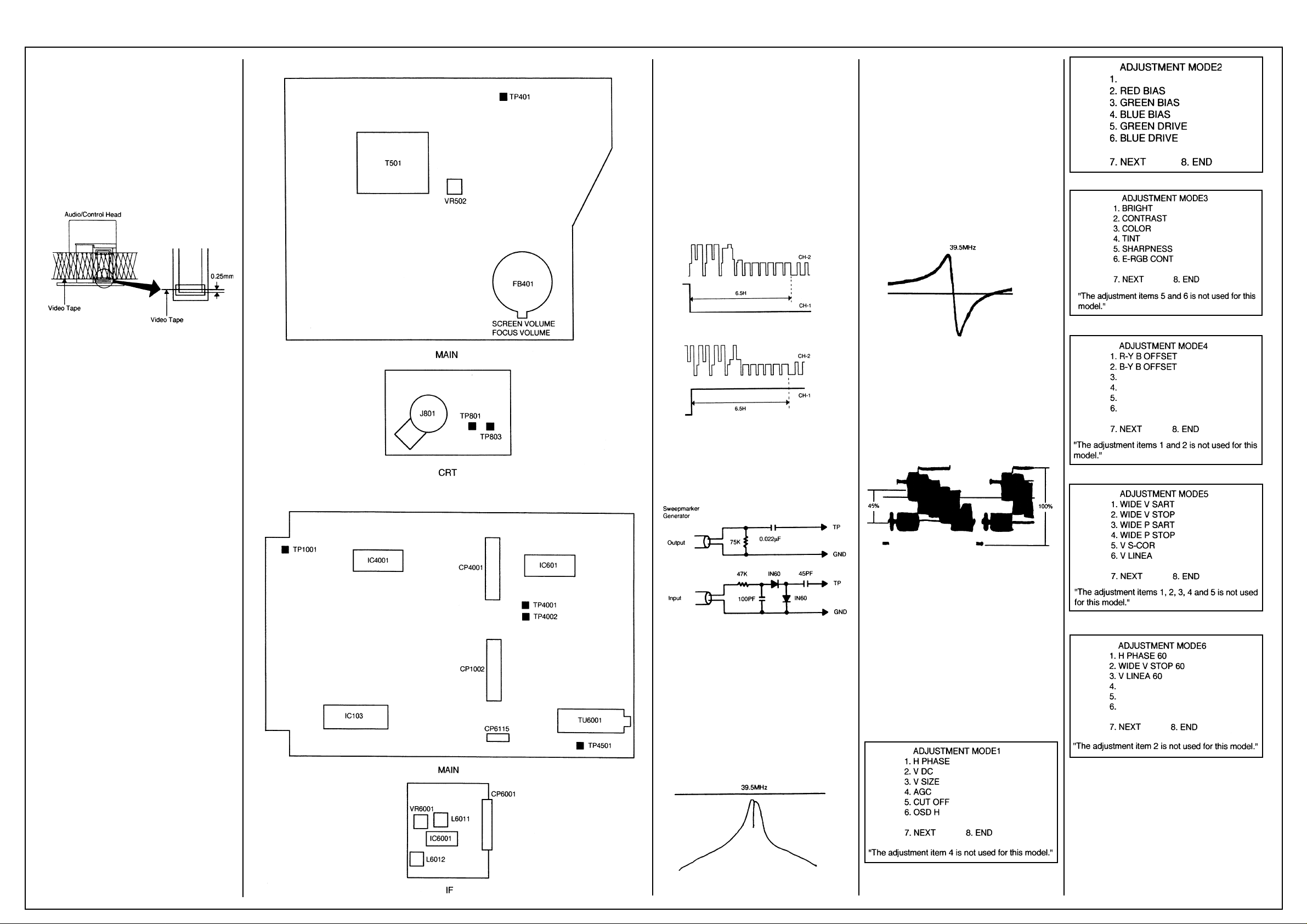
Components Location (TV)
Components Location (VCR)
(If the previous adjustments don’t work well:)
1. Connect CH-1 on the oscilloscope to TP4001
and CH-2 to TP4501.
2. Playback the alignment tape. (JG001F)
3. Set the tracking control to the center position.
(Refer to item 2-1, NO. 2.)
4. Press the VOL. DOWN button on the set and
the channel button (3) on the remote control
simultaneously until the indicator REC
disappears.
5. When the REC indicator is blinking, press
both VOL. DOWN key on the set and the
channel button (4) on the remote control
simultaneously and adjust the Tracking +/button until the arising to the down of the
Head Switching Pulse becomes 6.5 ± 0.5 H.
6. Press the Tracking Auto button.
Fig. 3-1-A
Fig. 3-1-B
3-2: VCO COIL
NOTE
For adjusting of VCO, connect input and output
terminals of sweepmarker generator to the
circuit as shown, then adjust it.
3-3: AFT COIL
CONDITION
MODE-STOP
INSTRUCTIONS
1. Connect the output of sweepmarker generator
to pin 5 of IC6001.
2. Connect the input of sweepmarker generator
to pin 3 of CP6115.
3. Adjust L6012 until the waveform marker
(38.9MHz) becomes as shown in Fig. 3-3.
4. Disconnect the sweepmarker generator and
the oscilloscope.
5. Connect the generator (39.5MHz) to the pin 4
of CP6115 through 2.2K ohm and connect the
DC voltmeter to pin 3 of CP6115.
6. Adjust L6012 until the DC voltage at pin 3 of
CP6115 is 3.8V±0.1V.
Fig. 3-3
3-4: COLOR LEVEL
CONDITIONS
MODE-STOP
INSTRUCTIONS
1. Connect the oscilloscope to TP4501.
2. When the Y-LEVEL is 100%, adjust the
VR6001 until the MAGENTA Section LEVEL
becomes 45± 5%. (Refer to Fig. 3-4)
Fig. 4-2
Fig. 4-3
Fig. 4-4
(VCR SECTION)
Components Location
3. ADJUSTMENT PROCEDURE
Read and perform these adjustments when
repairing the circuits or replacing electrical parts
or PCB assemblies.
CAUTION
When replacing IC’s or transistors, use a silicon
grease. (To prevent the damage to IC’s and
transistors.)
3-1: PG SHIFTER (HEAD SWITCHING)
ADJUSTMENT CONDITIONS
MODE-PLAYBACK
Input Signal-Alignment Tape (JG001F) or Similar
INSTRUCTIONS
1. Unplug the AC plug once to set the clock to
the non-setting state. Then, set the volume
level to minimum.
2. Playback the alignment tape. (JG001F)
3. Set the tracking control to the centre position.
Refer to item 2-1, NO. 2.)
4. Press the VOL. DOWN button on the set and
the channel button (3) on the remote control
simultaneously until the indicator REC
disappears. If the indicator REC disappears,
adjustment is completed.
CONDITION
MODE-STOP
INSTRUCTIONS
1. Connect the output of sweepmarker generator to pin 5 of IC6001.
2. Connect the input of sweepmarker generator
to pin 17 of IC6001.
3. Connect a 10K ohm variable resistor to IF
AGC terminal (pin 4 of IC6001), 9V line and
ground, then adjust to make the waveform of
the oscilloscope readable.
4. Adjust L6011 until the waveform marker
(39.5MHz) becomes as shown in Fig. 3-2.
Fig. 3-2
Fig. 3-4
Electrical Adjustments (TV SECTION)
4. BASIC ADJUSTMENTS
On-Screen Display Adjustment
Do not set the CLOCK, and sound to minimum.
Press the VOL. DOWN key on the set and the
Channel button (9) on the remote control
simultaneously to appear the adjustment mode
on the screen as shown in Fig. 4-1, Fig. 4-2, Fig.
4-3, Fig. 4-4, Fig. 4-5 and Fig. 4-6.
NOTE
Use the 1 - 7 keys on the remote control to
select the options shown in Fig. 4-1, Fig. 4-2,
Fig. 4-3, Fig. 4-4, Fig. 4-5 and Fig. 4-6.
Press the 8 key to end the adjustments.
Fig. 4-1
Fig. 4-5
Fig. 4-6
4-1: CUTOFF
1. Activate the adjustment mode display of Fig.
4-1 and press the channel button (5) on the
remote control.
2. Adjust the Screen Volume until picture is
distinct.
4-2: WHITE BALANCE
1. Receive the color bar pattern.
2. Adjust the adjustment mode display of Fig. 4-2
until the white color is looked like a white.
Page 5
AIWA VX-T1480
Electrical Adjustments
Cont’d
4-3: FOCUS
1. Receive the broadcasting signal.
2. Adjust the Focus Volume until picture is
distinct.
4-4: HORIZONTAL PHASE
1. Receive the color bar pattern.
2. Using the remote control, set the brightness
and contrast to normal position.
3. Activate the adjustment mode display of Fig.
4-1 and press the channel button (1) on the
remote control.
4. Press the VOL. UP/DOWN button on the
remote control until the SHIFT quantity of the
OVER SCAN on right and left becomes
minimum.
4-5: VERTICAL POSITION
1. Receive the color bar pattern.
2. Using the remote control, set the brightness
and contrast to normal position.
3. Activate the adjustment mode display of Fig.
4-1 and press the channel button (2) on the
remote control.
4. Press the VOL. UP/DOWN button on the
remote control until the horizontal line of the
color bar comes to approximate center of the
CRT.
4-6: VERTICAL SIZE
1. Receive the monochrome pattern.
2. Using the remote control, set the brightness
and contrast to normal position.
3. Activate the adjustment mode display of Fig.
4-1 and press the channel button (3) on the
remote control.
4. Press the VOL. UP/DOWN button on the
remote control until the horizontal overscan is
equal to the vertical overscan.
4-7: VERTICAL LINEA
1. Receive the monochrome pattern.
2. Using the remote control, set the brightness
and contrast to normal position.
3. Activate the adjustment mode display of Fig.
4-5 and press the channel button (6) on the
remote control.
4. Press the VOL. UP/DOWN button on the
remote control until the SHIFT quantity of the
OVER SCAN on upside and downside
becomes minimum.
4-8: HORIZONTAL PHASE 60 (AV)
1. Receive the monochrome pattern (Audio
Video Input).
2. Using the remote control, set the brightness
and contrast to normal position.
3. Activate the adjustment mode display of Fig.
4-6 and press the channel button (1) on the
remote control.
4. Press the VOL. UP/DOWN button on the
remote control until the SHIFT quantity of the
OVER SCAN on right and left becomes
minimum.
4-9: VERTICAL LINEA 60 (AV)
1. Receive the monochrome pattern (Audio
Video Input).
2. Using the remote control, set the brightness
and contrast to normal position.
3. Activate the adjustment mode display of Fig.
4-6 and press the channel button (3) on the
remote control.
4. Press the VOL. UP/DOWN button on the
remote control until the SHIFT quantity of the
OVER SCAN on upside and downside
becomes minimum.
4-10: OSD HORIZONTAL
1. Using the remote control, set the brightness
and contrast to normal position.
2. Activate the adjustment mode display of Fig.
4-1 and press the channel button (6) on the
remote control.
3. Press the VOL. UP/DOWN button on the
remote control until the difference of A and B
becomes minimum. (Refer to Fig. 4-7)
Fig. 4-7
4-11: SUB CONTRAST (TV)
1. Receive the monochrome pattern (RF Input).
2. Activate the adjustment mode display of Fig.
4-3 and press the channel button (2) on the
remote control.
3. Press the VOL. UP/DOWN button on the
remote control until the CONTRAST level is
set to the 20”.
4-12: SUB CONTRAST (AV)
1. Receive the monochrome pattern (Audio
Video Input).
2. Activate the adjustment mode display of Fig.
4-3 and press the channel button (2) on the
remote control.
3. Press the VOL. UP/DOWN button on the
remote control until the CONTRAST level is
set to the “20”.
4-13: SUB BRIGHTNESS (TV)
1. Receive the monochrome pattern (RF Input).
2. Using the remote control, set the brightness
and contrast to normal position.
3. Activate the adjustment mode display of Fig.
4-3 and press the channel button (1) on the
remote control.
4. Press the VOL. UP/DOWN button on the
remote control until the white 25% is slightly
brilliant.
4-14: SUB BRIGHTNESS (AV)
1. Receive the monochrome pattern (Audio
Video Input).
2. Using the remote control, set the brightness
and contrast to normal position.
3. Activate the adjustment mode display of Fig.
4-3 and press the channel button (1) on the
remote control.
4. Press the VOL. UP/DOWN button on the
remote control until the white 25% is slightly
brilliant.
4-15: SUB COLOR (TV)
1. Receive the color bar pattern (RF Input).
2. Connect the oscilloscope to TP801.
3. Activate the adjustment mode display of Fig.
4-3 and press the channel button (3) on the
remote control.
4. Adjust the VOLTS RANGE VARIABLE knob of
the oscilloscope until the range between white
100% and 0% is set to 4 scales on the screen
of the oscilloscope.
5. Press the VOL. UP/DOWN button on the
remote control until the red color level is
adjusted to 95% (VX-T1480) or 85% (VXG140) of the white level. (Refer to Fig. 4-8)
Fig. 4-8
4-16: SUB COLOR (AV)
1. Receive the color bar pattern (Audio Video
Input).
2. Connect the oscilloscope to TP801.
3. Activate the adjustment mode display of Fig.
4-3 and press the channel button (3) on the
remote control.
4. Adjust the VOLTS RANGE VARIABLE knob of
the oscilloscope until the range between white
100% and 0% is set to 4 scales on the screen
of the oscilloscope.
5. Press the VOL. UP/DOWN button on the
remote control until the red color level is
adjusted to 95% (VX-T1480) or 85% (VXG140) of the white level. (Refer to Fig. 4-8).
4-17: SUB TINT (AV)
1. Receive the color bar pattern (Audio Video
Input).
2. Connect the oscilloscope to TP803.
3. Activate the adjustment mode display of Fig.
4-3 and press the channel button (4) on the
remote control.
4. Press the VOL. UP/DOWN button on the
remote control until the waveforn becomes as
shown in Fig. 4-9.
Fig. 4-9
4-18: CONSTANT VOLTAGE
1. Receive the monochrome pattern.
2. Using the remote control, set the brightness
and contrast to minimum position.
3. Connect the DC voltmeter to TP401.
4. Adjust the VR502 until the DC voltmeter is
100V ± 0.5V.(VX-T1480) or 103V ± 0.5V (VXG140).
5. PURITY AND CONVERGENCE ADJUST-
MENT
NOTE
1. Turn the unit on and let it warm up for at least
30 minutes before performing the following
adjustments.
2. Place the CRT surface facing east or west to
reduce the terrestrial magnetism.
3. Turn ON the unit and demagnetize with a
Degauss Coil.
5-1: STATIC CONVERGENCE (ROUGH
ADJUSTMENT)
1. Tighten the screw for the magnet. Refer to the
adjusted CRT for the position. (Refer to Fig.
5-1). If the deflection yoke and magnet are in
one body, untighten the screw for the body.
2. Receive the green raster pattern from color
bar generator.
3. Slide the deflection yoke until it touches the
funnel side of the CRT.
4. Adjust center of screen to green, with red and
blue on the sides, using the pair of purity
magnets.
5. Switch the color bar generator from the green
raster pattern to the crosshatch pattern.
6. Combine red and blue of the 3 color crosshatch pattern on the center of the screen by
adjusting the pair of 4 pole magnets.
7. Combine red/blue (magenta) and green by
adjusting the pair of 6 pole magnets.
8. Adjust the crosshatch pattern to change to
white by repeating steps 6 and 7.
5-2: PURITY
NOTE
Adjust after performing adjustments in section 5-1.
1. Receive the green raster pattern from color
bar generator.
2. Adjust the pair of purity magnets to center the
color on the screen. Adjust the pair of purity
magnets so the color at ends are equally
wide.
3. Move the deflection yoke backward (To neck
side) slowly, and stop it at the position when
the whole screen is green.
4. Confirm red and blue colors.
5. Adjust the slant of the deflection yoke while
watching the screen, then tighten the fixing
screw.
Fig. 5-1
5-3: STATIC CONVERGENCE
NOTE
1. Receive the crosshatch pattern from color bar
generator.
2. Combine red and blue of the 3 color crosshatch pattern on the center of the screen by
adjusting the pair of 4 pole magnets.
3. Combine red/blue (magenta) and green by
adjusting the pair of 6 pole magnets.
5-4: DYNAMIC CONVERGENCE
NOTE
Adjust after performing adjustments in section 5-3.
1. Adjust the differences around the screen by
moving the deflection yoke upward/downward
and right/left. (Refer to Fig. 5-2-a)
2. Insert three wedges between the deflection
yoke and CRT funnel to fix the deflection
yoke. (Refer to Fig. 5-2-b)
Fig. 5-2-a
Fig. 5-2-b
OVD-5 Deck Alternative Parts
Page 6
AIWA VX-T1480
OVD-5 Deck Alternative Parts Cont’d
Page 7
AIWA VX-T1480
OVD-5 Deck Alternative Parts Cont’d
Earphone Diagram
Page 8
AIWA VX-T1480
Deck Exploded Parts View
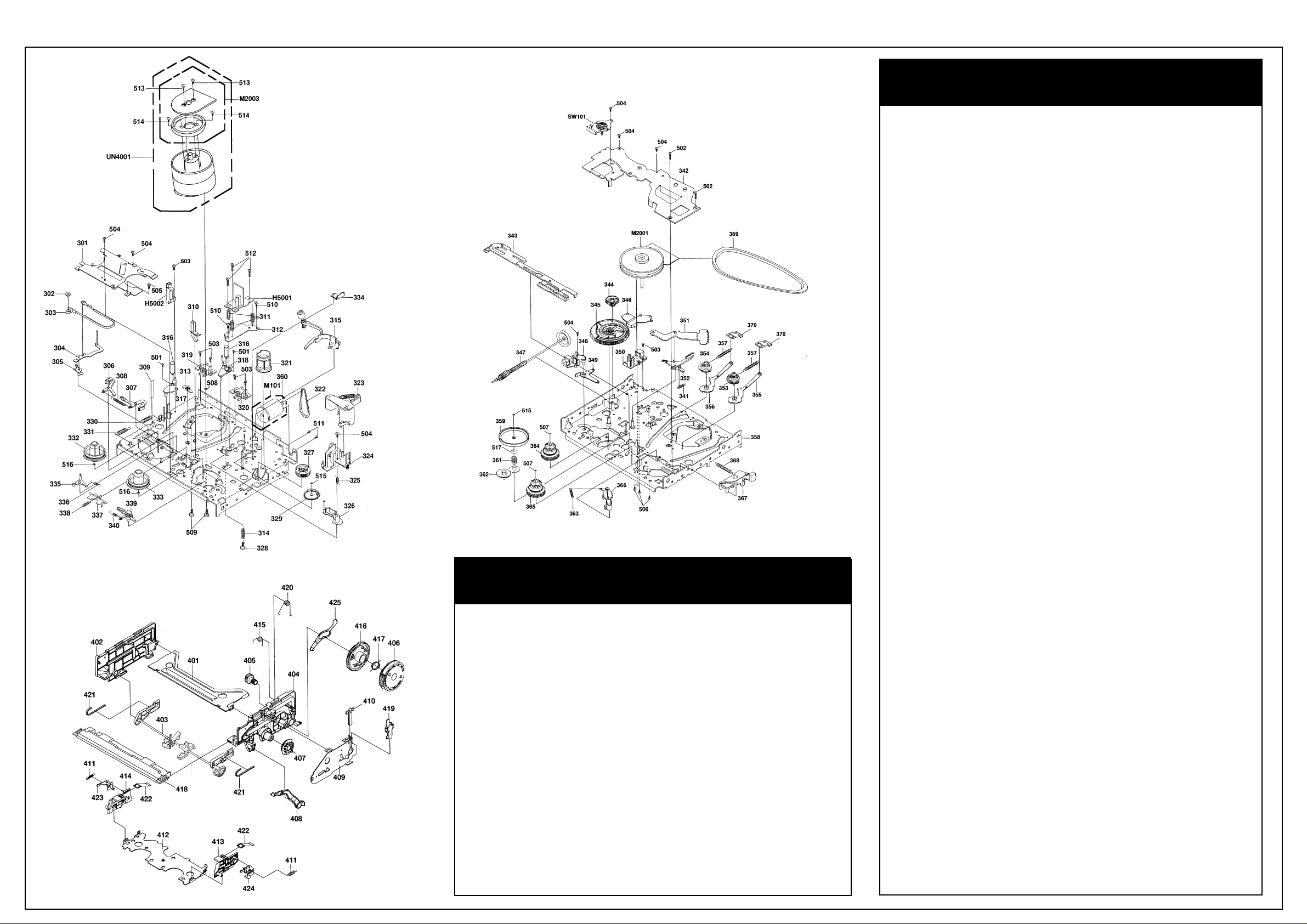
Item Part No. Description
301 S5-OP6-004-710 BRACKET, BRAKE 1
302 S5-OP4-003-580 ADJUST, TENSION 1
303 S5-OA4-001-220 TENSION BAND ASSY 1
304 S5-OA4-001-240 TENSION ARM ASSY
305 S5-OA4-001-230 TENSION LEVER 2 ASSY 1
306 SS-OA6-001-550 MAIN BRAKE S ASSY
307 S5-OA6-001-560 MAIN BRAKE T ASSY 1
308 S5-OP8-002-520 SPR,MAIN BRAKE 1
309 S5-OP9-005-640 REFLECTOR EOT 1
310 SS-OP4-004-110 REFLECTOR, LED 2 1
311 S5-OP8-002-690 SPR, AC HEAD 3
312 S5-OP5-000-600 BASE, AC HEAD 1
313 S5-OP0-003-940 POST, C ASS GUIDE L 1
314 SS-OP8-002-450 SPRING, AZIMUTH 2 1
315 S5-OA5-000-130 AHC ASSY 1
316 S5-OA4-001-020 G-ROLLER ASS’Y 2
317 S5-OA4-001-140 BASE, S INCLINED ASSY 1
318 S5-OA4-001-150 BASE, T INCLINED ASSY 1
319 S5-OP4-003-300 CATCHER S 1
320 S5-OP4-003-320 CATCHER T 1
321 S5-OP4-003-430 CAMPINCH ROLLER 1
322 S5-OP6-004-870 BELT, LOADING 1
323 S5-OA4-001-170 PINCH ROLLER BLOCK 1
324 S5-OP9-005-410 CASS, OPENER 1
325 S5-OP8-002-640 SPR, P5 1
326 S5-OA4-001-200 PS ARM ASSY 1
327 S5-OP4-003-420 CAM, GEAR 1
328 S1-462-30A-140 VT2+3-1 1 1
329 S5-OP4-003-440 CAM, P5 1
330 S5-OP4-003-560 SPR, TENSION ARM 2 1
331 S5-OP4-003-570 SPR, TENSION ARM 1 1
332 S5-OP2-002-160 REEL S 1
Deck Parts List
Deck Parts List Cont’d
Item Part No. Description
333 S5-OP2-002-170 REEL T 1
334 S5-OP4-004-020 CATCHER, P52 1
335 S5-OP6-004-65O SUBBRAKE S 1
336 S5-OP8-002-530 SPR, S-S BRAKE 1
337 S5-OP2-002-470 ARM, JOINT 1
338 S5-OP8-002-620 SPR, JOINT ARM 1
339 S5-OA6-001-570 SUB BRAKE T ASSY 1
340 S5-OP8-002-540 SPR,T-S BRAKE 1
341 S5-OP8-002-550 5PR,CAPBRAKE 1
342 PLATE BOTTOM 1
343 S5-OA6-001-760 ROD MAIN ASSY 1
344 S5-OP4-003-410 GEAR, MIDDLE 1
345 S5-OP6-005-350 CAM MAIN 1
346 S5-OP6-004-680 LEVER MAIN BRAKE 1
347 S5-OA6-001-590 WORM ASSY 1
348 S5-OP6-004-830 BRACKET, WORM F 1
349 S5-OP6-004-740 LEVER, RATCHET 1
350 S5-OP6-004-840 BRACKET, WORM R 1
351 S5-OP3-001-510 LEVER,LOADING 1
352 CAPSTAN BRAKE ASSY (MJ) 1
353 S5-OP3-001-520 GEAR, LOADING S 1
354 S5-OP3-001-530 GEAR, LOADING T 1
355 S5-OA3-000-530 LOADING ARM S ASS’Y 1
356 S5-OA3-000-540 LOADING ARM T ASS’Y 1
357 S5-OP8-002-630 SPR,LOADING GEAR 2
358 MAIN CHASS ASSY 1
359 S5-OP2-002-130 CENTER PULLEY 1
360 S5-OP6-004-860 PULLEY LDM 5 1
361 S5-OP8-002-610 SPR, C-PULLEY 1
362 S5-OA2-000-650 ARM IDLER ASSY 1
363 S5-OP8-002-700 SPR,LEVER TENSION 1
364 S5-OA2-000-640 CLUTCH GEAR T ASSY 1
365 S5-OA2-000-630 CLUTCH GEAR S ASSY 1
366 S5-OP4-003-600 LEVER, TENSION 1
367 S5-OP4-003-590 HOLDER, TENSION 1
368 S5-OP8-002-560 SPR, MAIN ROD 1
369 S5-OP2-002-1S0 BELT,CAPSTAN 1
370 S5-OP3-001-500 SLIDER, LOADING 2
401 S5-OP9-006-170 BRKET , TOP 1
402 S5-OP9-006-070 BRACKET, SIDE L 1
403 S5-OA9-001-710 LINK ASSY 2 1
404 S5-OP9-006-150 BRKET, SIDER 1
405 S5-OP9-006-010 GEAR, JOINT 1
406 S5-OP9-006-020 GEAR, CAM 1
407 S5-OP9-006-090 GEAR, LINK R 1
408 S5-OP9-006-720 LEVER,FLAP 2 1
409 S5-OP9-006-160 BRKET, SIDE R2 1
410 ---- REFLECTOR, EOT 1
411 S5-OP8-002-960 SPR, LOCKER 2
412 S5-OP9-006-110 CASS, HOLDER 1
413 S5-OP9-006-130 CASS, SIDE R 1
414 S5-OP9-006-120 CASS, SIDE L 1
415 S5-OP8-002-980 SPR, BRACKET R 1
416 S5-OP9-006-080 GEAR, CLUTCH 1
417 S5-OP8-002-970 SPR, CLUTCH 1
418 S5-OP9-006-190 TAPE GUIDE PIECE 1
419 S5-OP9-006-200 COVER,SENSOR BOT 1
420 S5-OP8-002-900 SPR, EARTH 1
421 S5-OP8-002-940 SPR, LINK 2
422 S5-OPB-002-990 SPR, PACK 2
423 S5-OP9-006-050 LOCKER, L 1
424 S5-OP9-006-060 LOCKER, R 1
425 S5-OP9-006-100 LEVER, BOT 1
501 87-357-529-310 SCREW TAP(P)BIND 1.7-4.0 2
502 S1-092-26A-640 VT2+2.6-16 2
503 87-751-074-410 VT2+2.6-8 6
504 87-743-073-010 VT2+2.6-6 7
505 S1-071-236-040 SCREW, TAP 23-6 PAN 1
506 87-264-074-410 SCREW, TAP(B)PAN 26-8 3
507 S2-P16-600-5N0 POLY, W(CUT)1.6-6-0.5 2
508 S2-Q31-54B-3N0 PW, 3.1-5.4-T0.13 1
509 S1-0A1-306-040 SCREW, WASHER(A)M3-6 3
510 S1-0B1-266-040 UFT2+M2.6-6 2
511 87-258-091-010 U+M3-3 2
512 87-253-07S-010 U+M2.6-10 3
513 S1-0A1-235-040 SEMS A M2.3-5 2
S14 87-261-093-410 SCREW, M3-5 2
515 87-067-909-010 POLY, W(CUT)2.6-6-0.5 2
516 S2-Q26-471-3N0 POLY, W 2.6-47-0.13 2
517 S2-P26-A00-5N0 POLY, W(CUT)2.6-10-0.5 1
CD1001 S6-872-205-8A0 CORD CONN 8722058A 1
CD2001 ---- JUMPER 2W06080 1
CD5001 ---- CORD, JUMPER 2L05150 1
H5001 S5-23D-910-290 HEAD, AC HVMZA12 1
H5002 S5-43D-020-100 HEAD,FULL ERASE HVFHF00 1
M101* S5-96P-480-010 MOTOR, LOAD(1) 1
M2001* S5-94J-980-040 CAPSTAN DD UNIT SP39BD 1
M2003* S5-89V-110-040 MICRO MOTOR EP14BA 1
SW101 S5-202-440-030 SW, ROTARY SRZZ0B064A 1
UN4001* S4-841-1B5-000 CYLINDER UNIT ASSY 1
* Safety Parts
Page 9
AIWA VX-T1480
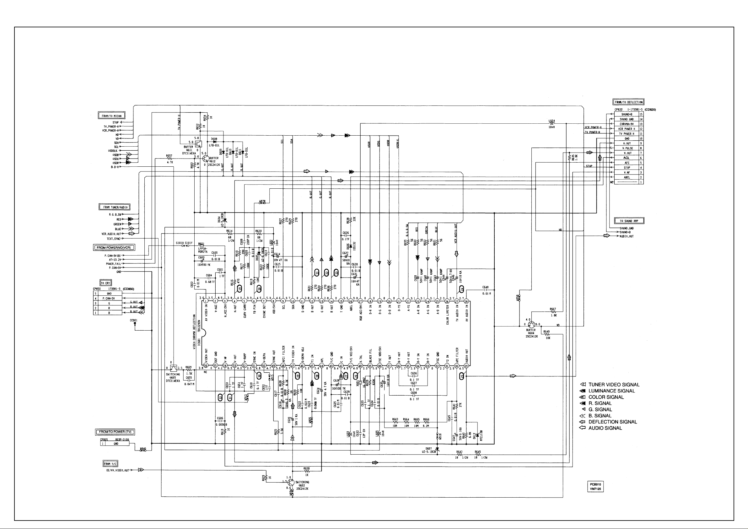
Chroma Diagram
Page 10
AIWA VX-T1480
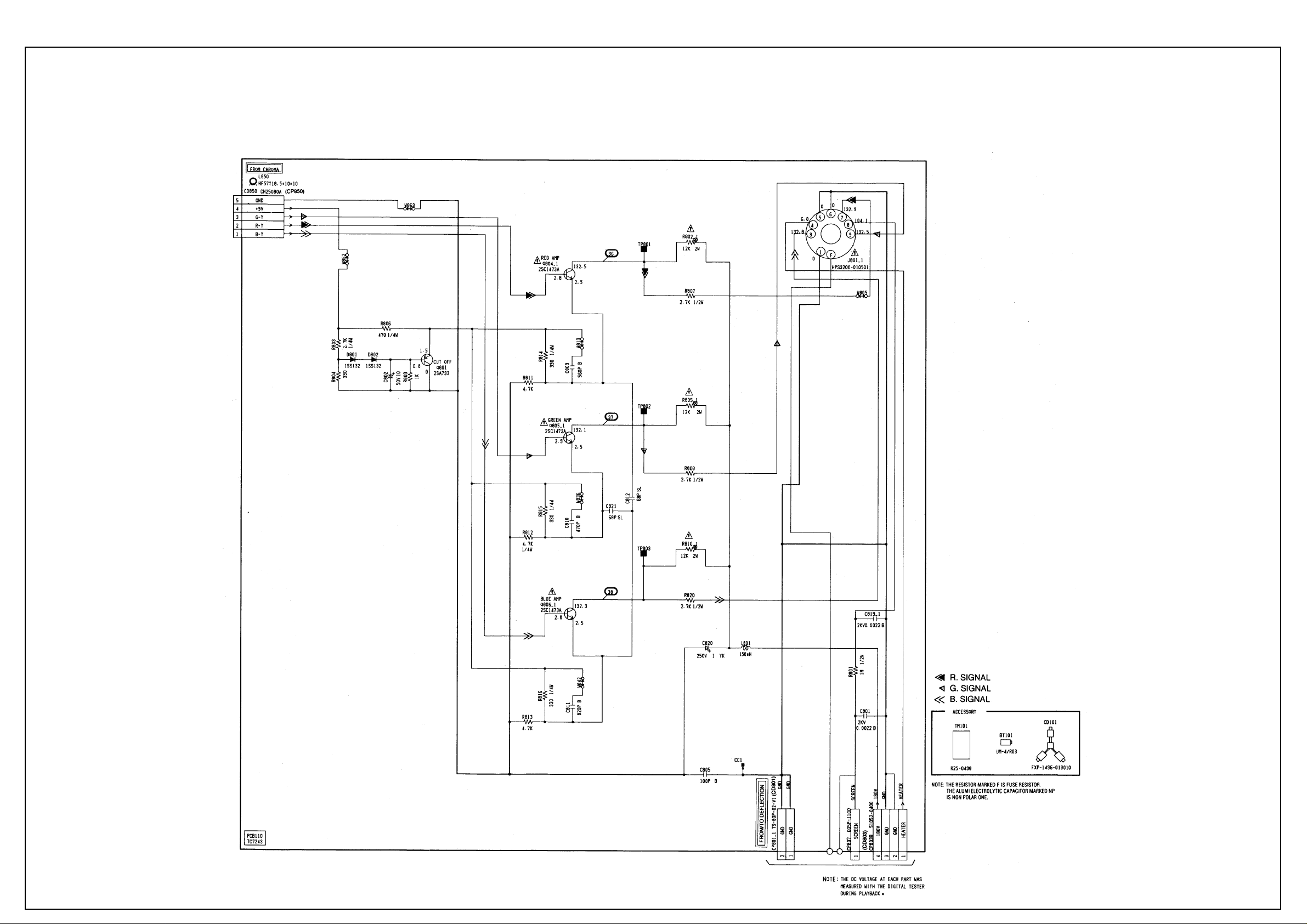
CRT Diagram
Page 11
AIWA VX-T1480
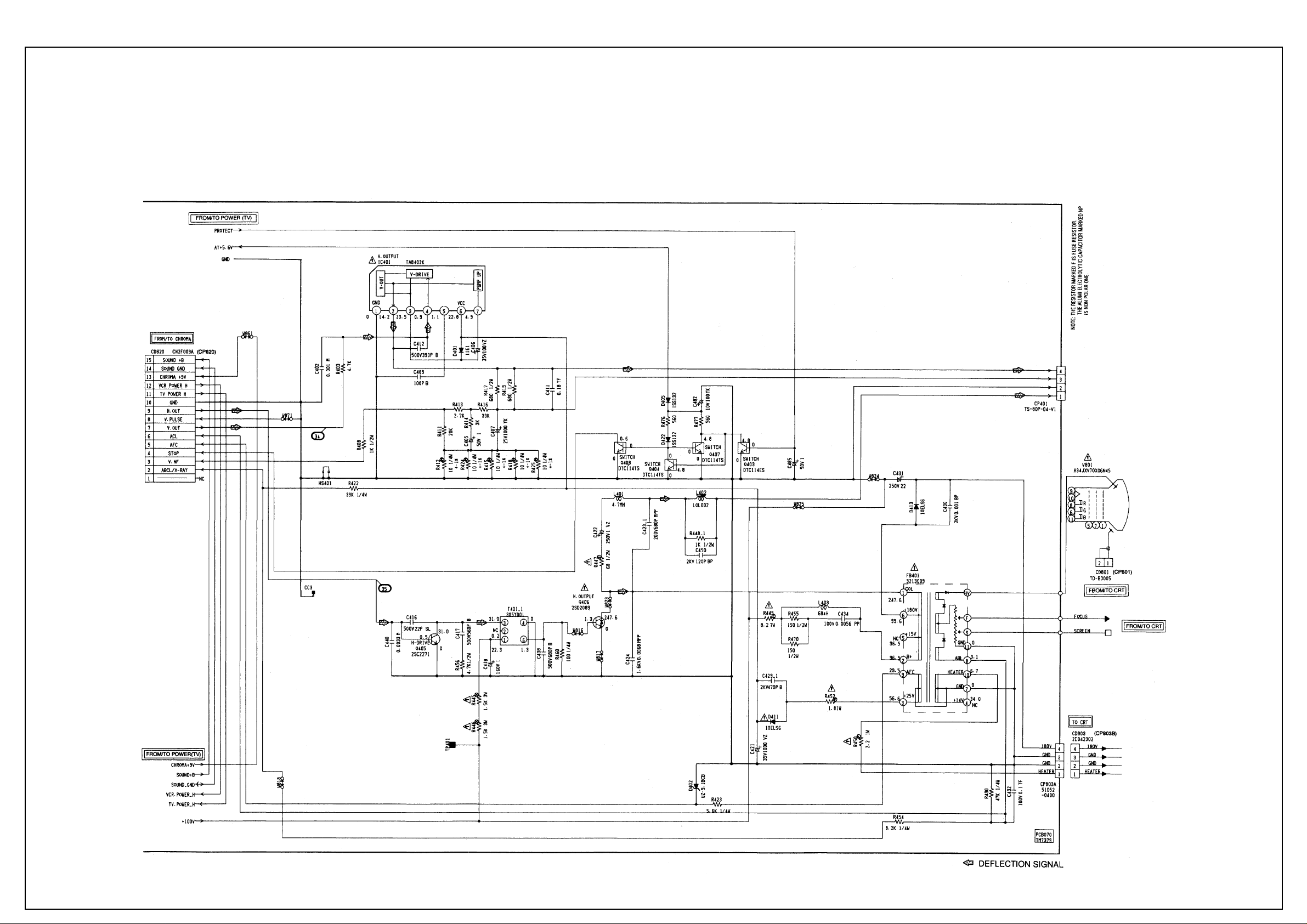
Deflection Diagram
Page 12
AIWA VX-T1480
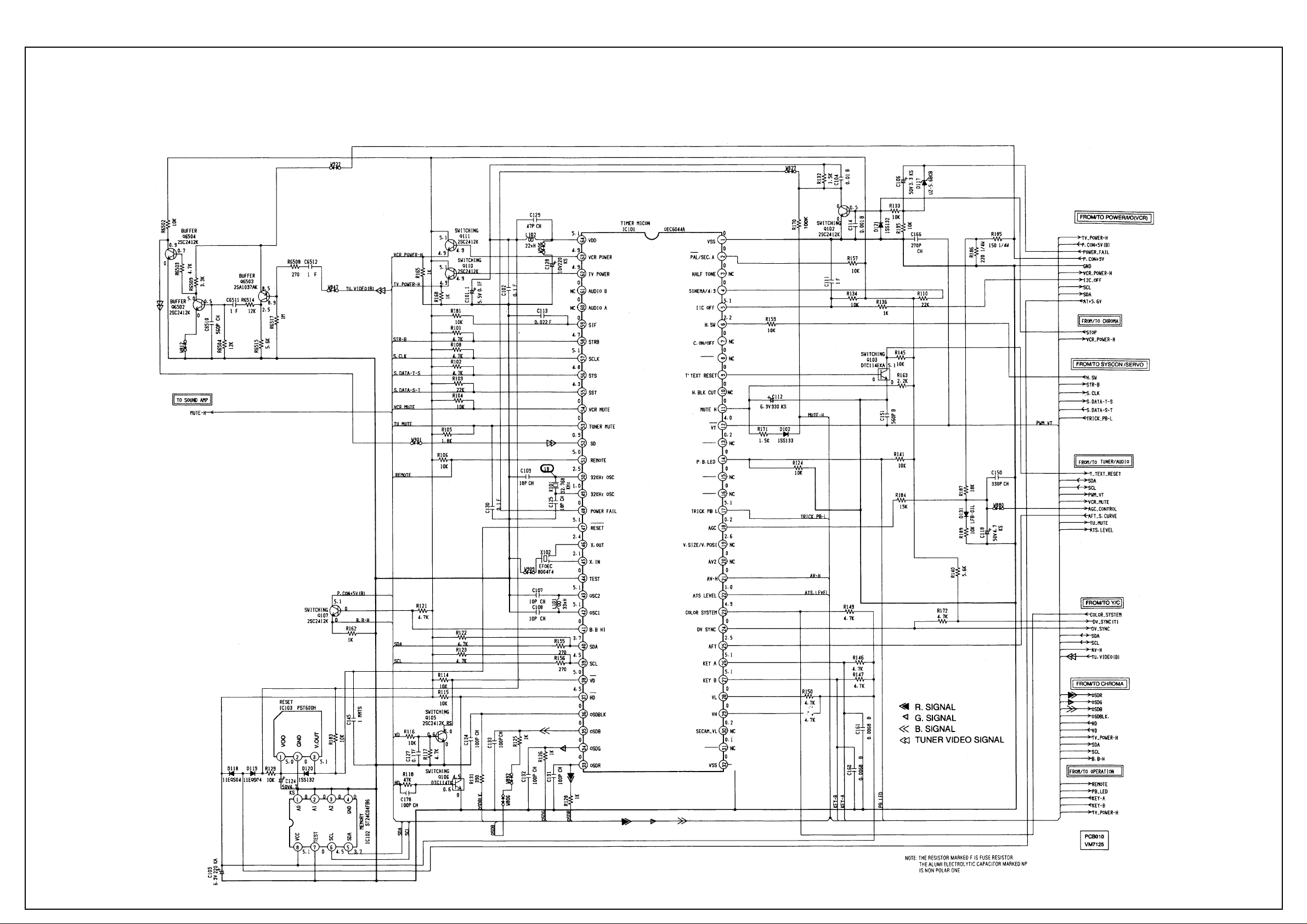
Microcontroller Diagram
Page 13
AIWA VX-T1480
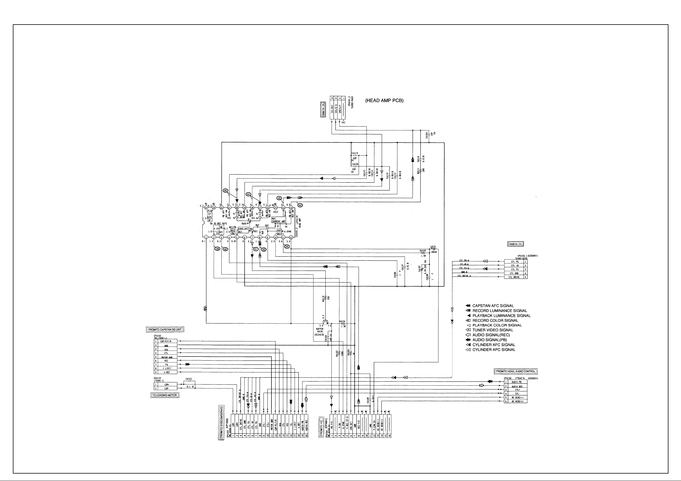
Head Amp Diagram
Page 14
AIWA VX-T1480
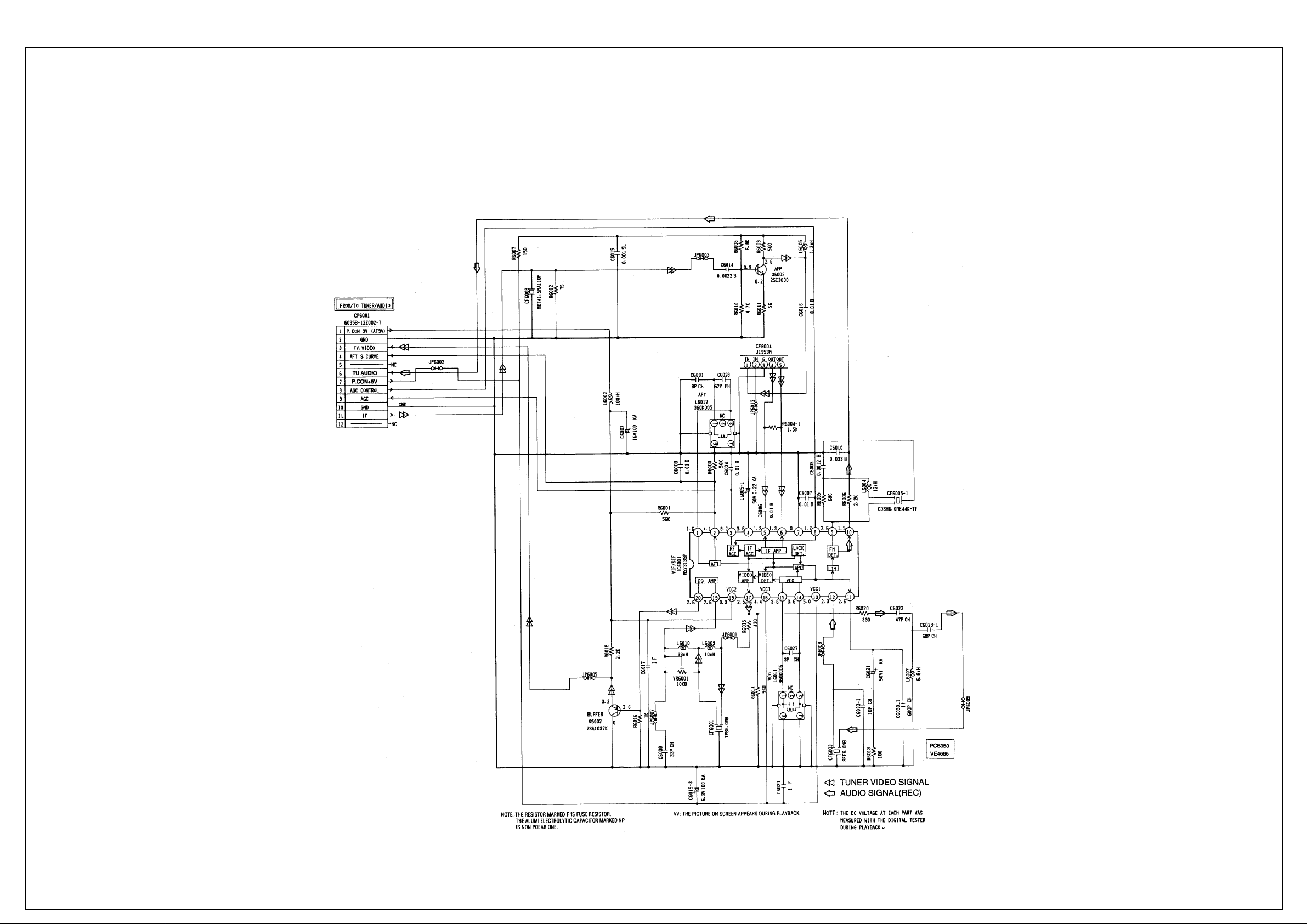
IF PCB Diagram
Page 15
AIWA VX-T1480
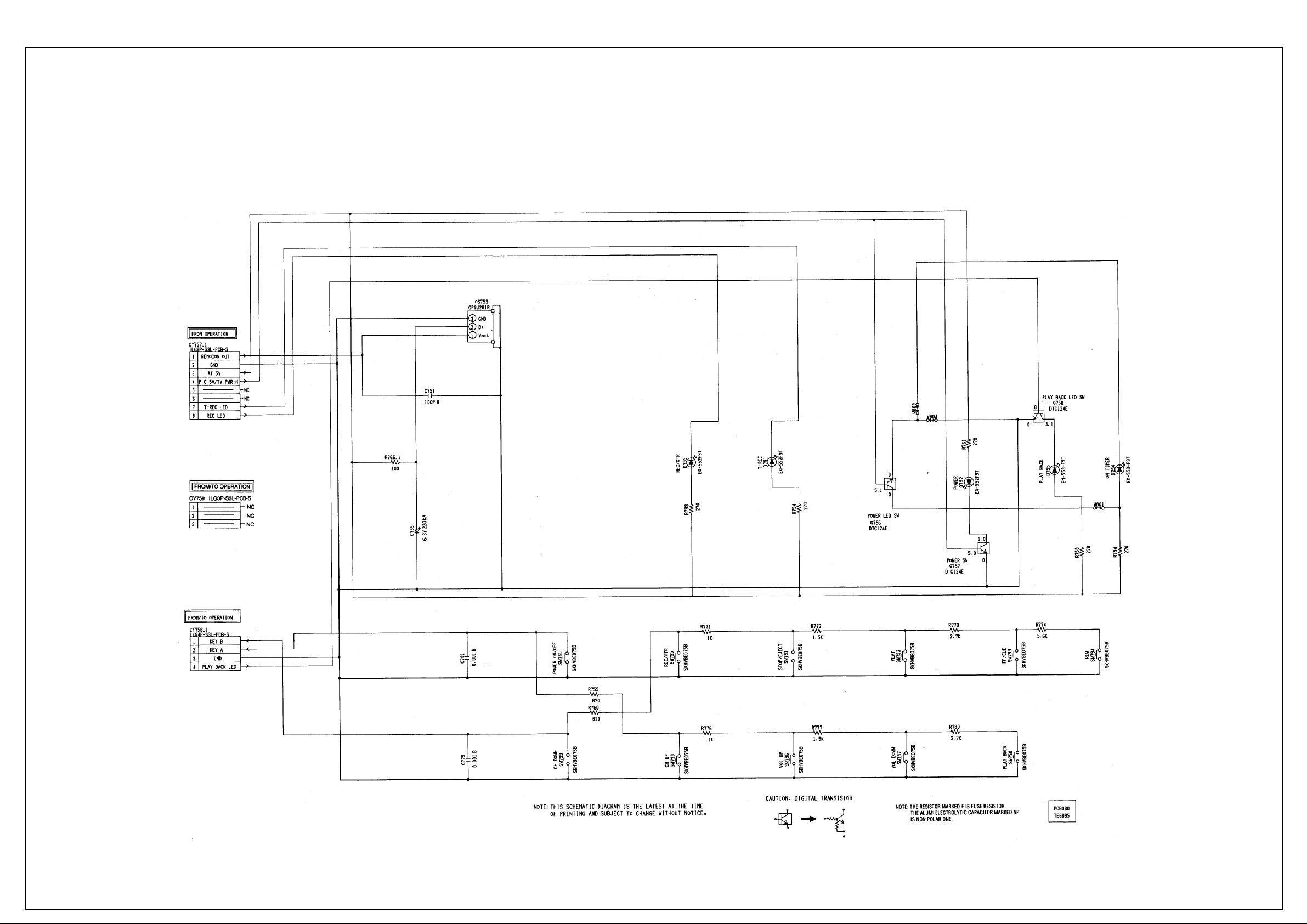
Operations Diagram 1
Page 16
AIWA VX-T1480
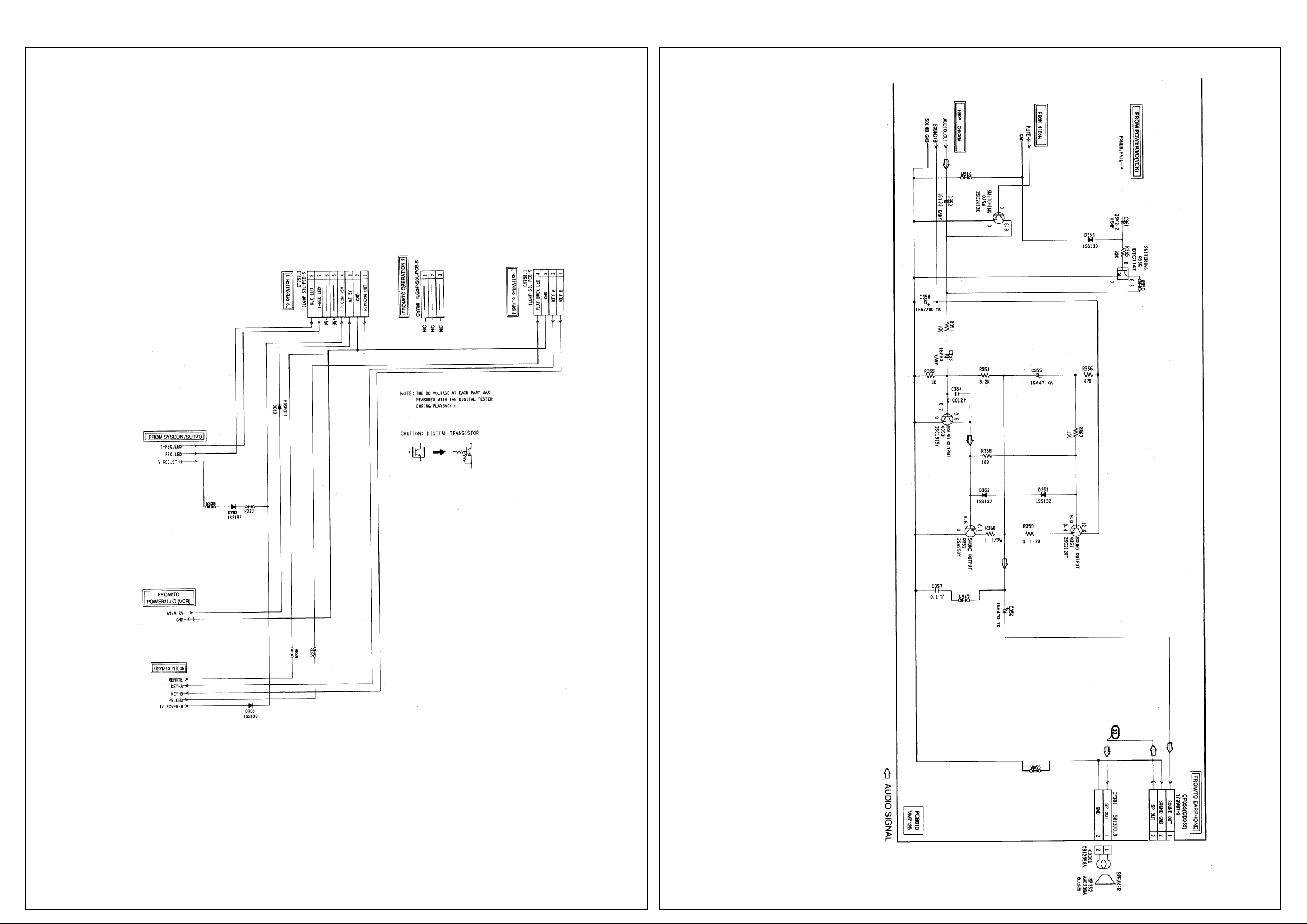
Operations Diagram 2
Audio Amp
Diagram
Page 17

AIWA VX-T1480
Power Diagram (TV)
Page 18

AIWA VX-T1480
Power Diagram (VCR)
Page 19

AIWA VX-T1480
Teletext Diagram
Page 20

AIWA VX-T1480
Y/C Diagram
Page 21

AIWA VX-T1480
T uner Audio Diagram
Page 22

AIWA VX-T1480
Waveforms
Page 23

AIWA VX-T1480
Wiring Diagram
Page 24

AIWA VX-T1480
System Control Servo Diagram
Page 25

(TV SECTION)
POWER DOES NOT TURN ON (1)
When turning on the
Power Switch, does the
LED light ?
Yes
Is the voltage at pin 1
of IC502 DC7.7V ?
Yes
Is the voltage at pin 3 of
IC502 DC5.6V ?
Yes
Does RY501 work ?
No
No
No
No No
Does the BASE voltage of
Q501 turn ON or OFF ?
Check P.CON 5V line.
Check IC502, D511 and D512.
Check IC502.
Check pins 62 and 63 of IC101 and
peripheral circuit.
Yes
Check IC506, Q507 and the
peripheral circuit.
Yes
Check Q504, RY501 and the
peripheral circuit.
Page 26

POWER DOES NOT TURN ON (2)
Is CP810 inserted ?
Yes
Is F501 broken ?
Yes
Replace F501.
No
No
Is the voltage at C507
about 160V ?
Yes
Q500 bad ?
Yes
Replace Q500.
No
No
Insert CD810.
Check the circuit between
F501, C507 and R501.
Check IC501 and the
peripheral circuit.
Page 27

GOOD PICTURE BUT NO SOUND
Is the voltage at CP301
changed with the volume
up or down key ?
Yes
Is the voltage at BASE of
Q351 and Q352 DC9V ?
Yes
Is the voltage at pin
1 corrector of Q351
DC9.2V ?
Yes
No
No
No
Is FUSE RESISTOR
(R517) broken ?
Yes
Replace FUSE RESISTOR (R517).
No
Check speaker and
EARPHONE PCB.
Check Sound +B line.
Check Q351 and Q352.
Is the voltage at pin 29
of IC601 changed from
DC10.8V to DC9.9V when
pressing VOLUME UP or
DOWN key ?
Yes
Check Q353 and peripheral circuit.
No
Check pin 28 of IC101, D612
and the peripheral circuit.
Page 28

NO PICTURE
Are the Brightness and
Contrast set to minimum ?
Yes
Is the voltage at pin 3 of
IC601 DC9V ?
Yes
Is the voltage at pin
17 of IC601 DC9V ?
Yes
Is the voltage at pin 41 of
IC601 DC5V ?
Yes
No
No
No
No
Adjust Brightness and Contrast.
Check P.CON 9.6V line.
Check CHROMA 9V line.
Check D607.
Is the voltage at pin 8,
38 of IC601 DC5V ?
Yes
Is the signal at pin 12, 13
and 14 of IC601 output ?
Yes
Is the waveform at TP801,
TP802 and TP803 of CRT
PCB output ?
Yes
Check J801 and CRT.
No
No
No
Is the waveform at pin 47
of IC601 normal ?
Yes
Check IC601.
No
Check D604.
Check Q602 and Video Out Line.
Check Q804, Q805, Q806 and CD850.
Page 29

NO COLOR
Is the color set to
minimum ?
Yes
Is the color signal
received ?
Yes
Is the waveform at pin
40 of IC601 normal ?
Yes
Is the waveform at pin 42
of IC601 normal ?
No
No
No
No
Adjust the color.
Receive the color signal.
Check peripheral circuit of X601.
Check peripheral circuit of VIDEO
out line and Q602.
Yes
Is the waveform 12, 13
and 14 of IC601 normal ?
Yes
Is the waveform at TP801,
TP802 and TP803 of CRT
PCB output.
Yes
Check J801 and CRT.
No
No
Check IC601.
Check Q804, Q805, Q806 and
CD850.
Page 30

ONLY A LINE APPEARS
Is the normal signal at
pin 4 of IC 401 input ?
Yes
Is the normal signal at
pin 38 of IC101 output ?
Yes
Is the voltage at pin 6 of
IC402 DC25V ?
Yes
Check peripheral circuit of IC402
and DY401.
OSD SCREEN DOES NOT APPEAR
No
No
No
Check peripheral circuit of IC601.
Check peripheral circuit of IC101.
Check R452 and FB401.
Is there a waveform at pins
33, 34 and 35 of IC101 ?
Yes
Is there a waveform at
pins 18, 19 and 20 of
IC601 ?
Yes
Check peripheral circuit of IC601.
No
No
Check pin 36 of IC101 and the
peripheral circuit.
Check pins 18, 19 and 20 of
IC601 and the peripheral circuit.
Page 31

(VCR SECTION)
PLAY SHUTS OFF
Insert a cassette and push
PLAY button.
Does it Power off in
about 3 seconds?
No
Does it Power off in
about 6 seconds?
No
Does it Power off
intermittently
No
Yes
Yes
Yes
Check TAPE LOADIG,
LOADING BELT,MODE SWITCH,
DD MOTOR and CYLINDER
MOTOR.
Check REEL SENSOR and
REEL BELT.
Check REEL SENSOR,IC1001
and REEL BELT slack.
Check IC1001.
Page 32

CYLINDER NOT ROTATING DURING PLAYBACK AND RECORDING
Is the voltage at pin 6 of
CP1002 about DC13V ?
Yes
In playback, is the
voltage at pin 3 of
CP1002 about DC1.2V ?
No
In playback, is the
voltage at pin 44 of
IC1001 DC5V Pulse and
is the voltage at pin 46 of
IC1001 about DC1.5V ?
Yes
No
Yes
No
Check UNREG 12V line
of Main PCB.
Replace CYLINDER MOTOR.
Check R1059, R1080 and R1058.
Replace IC1001.
Page 33

AUDIO SHAKES
Is AUDIO HEAD
scratched ?
No
Does pin 15 of IC1001
output a 3.0Vp-p square
wave ? 3.0V
Yes
In playback, is the voltage
at pin 14 of CP1002 2.8V ?
Is the voltage at pin 14 of
CP1002 3.3V when you
stop the CAPSTAN DD
MOTOR manually ?
Yes
Yes
No
No
Replace AUDIO HEAD.
Replace CAPSTAN DD.
Check peripheral components
of IC1001.
In playback, is the
voltage at pin 17 of
CP1002 about DC1.6V ?
Yes
Check AUDIO BLOCK.
No
In playback, is the voltage at
pin 50 of IC1001 3.8V ?
Yes
No
Replace IC1001.
Page 34

CASSETTE TAPE IS NOT ACCEPTED
Does WORM GEAR
of FRONT LOADING
UNIT activate ?
Yes
When cassette is not
inserted, is EOT BOT
PULSE at EMMITTER of
Q1055, Q1056 5V ?
Yes
When a cassette is inserted,
is the voltage between pins
1 and 2 of CP1002 ?
No
When a cassette is
inserted, is the voltage at
pin 49 of IC1001 5V ?
No
No
Yes
No
Does 8 MHz Clock
oscillate ?
No
Check WORM GEAR of
FRONT LOADING UNIT.
Check EOT, BOT, PHOTO
SENSOR, pins 2 and 4 of IC1001.
Replace LOADING MOTOR.
Replace X1001.
Yes
Check circuit of FRONT LOADING
MOTOR.
Yes
Replace IC1001.
Page 35

WHEN INSERTING CASSETTE, IT EJECTS IMMEDIATELY
In another cassette tape
does the same problem
appear ?
Yes
In covering the infrared
sensor, is pin 2 and 3 of
IC1001 5V ?
Yes
When inserting cassette,
is pin 4 of IC1001 low ?
Yes
Is EJECT position of
FRONT LOADING
GEAR OK ?
No
No
No
No
Defective CASSETTE or
FRONT LOADING UNIT.
Replace EOT/BOT PHOTO
TRANSISTORS.
Check R1010.
Check FRONT LOADING GEARS.
Yes
Check IC1001 circuit.
Page 36

FF/REW DO NOT WORK
When the FF/REW is pushed,
does the PULSE appear at
pin 51 of IC1001 ?
Yes
Is the voltage changing at
pin 12 of CP1002 when
you press FF/REW ?
Yes
Is the voltage changing
at pin 14 of CP1002 ?
Yes
Check DECK MECHANISM.
No
No
No
Check pin 74 of IC1001 lines change
IC1001.
Check pin 12 of CP1002 and
peripheal circuit.
Check pin 45 of IC1001 lines change
IC1001.
Page 37

TAPE LOADING IS OK, BUT UNLOADS IMMEDIATELY
Does CYLINDER rotate ?
Yes
Does TP4001 feed HEAD
SWITCHING PULSE
signal ?
30 Hz
No
No
Is the voltage at pin
6 of CP1002 UNREG
12V ?
Yes
In playback, is the
voltage at pin 3 of
CP1002 1.2V ?
Yes
Replace CYLINDER UNIT.
No
Does PG PULSE
signal appear at pin
13 of IC1001 ?
No
No
Check Power circuit.
Does DC5V PULSE signal
appear at pin 44 of IC1001 ?
Is the voltage at pin 46 of
IC1001 DC2.5V ?
Yes
Check R1059, R1080, R1058 and
D1003.
No
Yes
Does REEL SENSOR
PULSE signal appear at
pins 69 and 70 of IC1001 ?
No
Check REEL SENSOR.
Yes
Yes
Replace IC1001.
Page 38

PLAYBACK PICTURE JITTERS HORIZONTALLY
Is FG output level at pin 5
of CP1002 about 5V?
5V
Yes
Is the voltage at pin 3 of
CP1002 1.2V?
Yes
Replace CYLINDER MOTOR.
PLAYBACK PICTURE SHAKES
PLAYBACKPICTURE SHAKES
No
No
Replace CYLINDER MOTOR.
Replace IC1001.
Is FG Pulse output level at
pin 5 of CP1002 about 5V?
5V
Yes
Does pin 11 of IC1001
output a 4.4Vp-p square
wave?
Yes
In playback, is the voltage at
In playback, is the voltage
pin 3 of CP1002 about 1.2V?
at pin 3 of CP1002 about 1.2V?
When slowing CYLINDER, is
When sloeing CYLINDER,is
the voltage 3.8V?
the voltage 3.8V?
Yes
No
No
No
Replace CYLINDER MOTOR.
Replace CYLINDER MOTOR.
Replace IC1001.
Page 39

AUTO TRACKING DOES NOT OPERATE
By manual tracking,
does the DC level at pin 6
of CP4001 change?
Yes
In auto tracking, is the
voltage at pin 5 of IC1001
more than DC1.85V?
Yes Yes
No
No
Does the CTL PULSE
(about 1.0Vp-p) appear
at pin 19 of IC1001?
1.0Vp-p
No
Check IC4101 and
CYLINDER UNIT.
Check CONTROL HEAD.
Replace IC1001.
Page 40

WHEN PLAYBACK,FAST FORWARD OR REWIND MODE IS ACTIVATED, UNIT STOPS IMMEDIATELY
Does CAPSTAN DD
MOTOR rotate?
Yes
Is CAPSTAN BELT OK?
Yes
Does REEL SENSOR PULSE
signal appear at pin 69
of IC1001?
Yes
No
No
No
Refer to section "CAPSTAN
DD MOTOR NOT ROTATING"
Replace CAPSTAN BELT
Check REEL SENSOR and that
the voltage at pin 10 of CX1003
is DC5V.
Does REEL SENSOR PULSE
signal appear at pin 70
of IC1001?
Yes
Replace IC1001.
No
Check around pin 4 of IC1001.
Page 41

PLAYBACK PICTURE JITTERS VERTICALLY
No
Does tracking noise appear
in the picture?
Yes
By adjusting the manual tracking
UP/DOWN buttons,will the
noise disappear in the
picture?
Yes
Are GUIDE POSTS
the right height?
No
No
Check P/B ENVELOPE.
Adjust GUIDE POST height.
Yes
Is PG SHIFTER
Adjustment 6.5H?
Yes
Check PB-Y circuit.
No
Adjust PG SHIFTER.
Page 42

NO PLAYBACK PICTURE
Is E-E appearing on the
Monitor TV?
Yes
Is there PB Y/C signal at
TP4002?
Yes
Is there FM Y signal at
pin 11 of IC4001and there
CHROMA signal at pin
27 of IC4001?
Yes
No
No
No
Is the voltage at pins 12,28
and 54 of IC4001 5V?
Yes
Check 5V line.
No
Check Power circuit.
Check IC4101 and the
connection of the CYLINDER.
Check Q4001,Q4016,Q4004 and
the peripheral circuit.
Is there Y signal at
pin 27 of IC4001 and there
CHROMA signal at pin
31 of IC4001?
Yes
Is there Y signal at
pin 9 of IC4002 and there
CHROMA signal at pin
16 of IC4002?
Yes
Is there VIDEO signal at
pin 2 of IC4001?
Yes
No
No
No
Replace IC4001.
Check IC4002 and the
peripheral cicuit.
Replace IC4001.
Check J4501
Page 43

NO COLOR DURING PLAYBACK
Does FM ENVELOPE
appear at TP4002?
Yes
Does CHROMA signal
appear at pin 27 of IC4001?
Yes
Does COMPOSITE
signal appear at pin 16
of IC4002?
Yes
No
No
No
Check IC4101 and HEAD AMP
BLOCK.
Check C4067 and the peripheral
circuit.
Replace IC4002
Does COLOR BURST
signal appear in the
COMPOSITE signal
at pin 2 of IC4001?
Yes
Check TV Block.
No
Replace IC4001.
Page 44

PLAYBACK PICTURE NOISY (EVEN AFTER CLEANING HEADS)
Is FM signal at TP4002
more than 200mVp-p?
Yes
Is there FM signal at pin 11 of
IC4001 140mVp-p?
Yes
Is VIDEO waveform at
pin 6 of IC4001 over
500mVp-p and are
there any noise?
Yes
No
No
No
Replace CYLINDER MOTOR.
Check Q4001,Q4016,Q4004
and the peripheral circuit.
Check pins 6 and 8 of IC4002
and the peripheral circuit.
Is VIDEO waveform at
pin 37 of IC4001 400mVp-p
are there CHROMA signal
at pins 31 of IC4001 200mVp-p
and are there any noises?
Yes
Is VIDEO waveform at
pin 9 of IC4002 600mVp-p,
are there CHROMA signal
at pin 16 of IC4002 300mVp-p
and are there any noises?
Yes
Check J4501
No
No
Replace IC4001.
Replace IC4002.
Page 45

NO COLOR DURING SELF RECORDING AND PLAYBACK
Does VCR signal
appear at pin 53 of
IC4002 ?
Yes
Does CHROMA
signal appear at pin 29
of IC4001 ?
Yes
Does FM signal
appear at pin 8 of
CP4001 ?
Yes
Does FM signal
appear at pin 8 of
IC4101 ?
No
No
No
No
Replace J4501.
Check VIDEO input circuit.
Replace IC4001
Check Q4005, Q4006 and peripheral
circuit.
Check IC4101 and peripheral circuit.
Yes
Replace IC4101.
Page 46

NO NORMAL AUDIO ON PLAYBACK
Does audio appear on E-E ?
Yes
Is the voltage at pin 17
of IC5001 High ?
Yes
Does AUDIO signal
appear at pin 7 of
IC5001 ?
Yes
Check AUDIO HEAD for debris of
stains.
Check that the connector from AUDIO
HEAD is fully inserted to CP4106.
Replace IC 5001.
No
No
No
Refer to section "NO E-E".
If the pin 52 of IC1001 is not High,
replace the IC1001.
Check R5013, R5014 and peripheral
circuit.
Page 47

CAPSTAN DD MOTOR NOT ROTATION
In playback, is the
voltage at pin 13 of
CP1002 13V ?
Yes
Is the voltage at pin
15 of CP1002 5V ?
Yes
In playback, check the
voltage at pin 17 of
CP1002 is 2V or at pin
50 of IC1001 is 0V ?
Yes
No
No
No
Check POWER circuit.
Replace IC1001.
In playback, is the
voltage at pin 14 of
CP1002 2.5V ?
Yes
Replace IC1001.
Does DD MOTOR rotate now ?
If not, replace DD MOTOR.
No
Check pins between 45 and 47 of
IC1001 and peripheral circuit.
Page 48

AUDIO CAN NOT BE RECORDED
Is BIAS level O.K at
T5001 ? 60V
Yes
Is there AUDIO
signal at pin 10 or 12
of IC5001 ?
Yes
No
No
Is the voltage at pin 20
of IC5001 9.2V ?
Yes
T5001 is broken or shorted.
Check T5001 and peripheral circuit.
No
Check POWER circuit.
Check the circuit between audio
out of Tuner and pin 10 of IC5001.
Is there AUDIO signal
at pin 14 of IC5001 ?
Yes
Is there signal
at pin 22 of IC5001 ?
Yes
Check the lead wire and
connector to A/C HEAD.
No
No
Check IC5001 and peripheral
circuit.
Replace IC5001.
Page 49

CASSETTE IN AND DOWN, UNIT HAS NO FUNCTIONS
Does mode indicator
appear in Display ?
No
Does VCR operate with
the remote control ?
Yes
Check Operation PCB.
Yes
No
Check LOADING MOTOR, MODE
SWITCH and the peripheral parts.
Check IC1001.
Page 50

RECORDING MECHANISM WORKS, BUT NO VIDEO RECORDED FROM INPUT JACK OR TUNER
Does VIDEO signal
appear at pin 51 or 53
of IC4001 ?
Yes
Is there VIDEO signal at
pin 6 of IC4002 and
Does VIDEO signal appear at
pin 8 of IC4001 ?
Yes
Does FM signal appear
at pin 8 to CP4001 ?
Yes
Does the FM current
appear at pin 8 of IC4101
during the REC.
No
No
No
No
Check the circuit from VIDEO input
jack to IC4001, from Tuner Pack to
IC4001.
Check the peripheral circuit of Q4007,
Q4009.
Replace IC4001.
Replace IC4101.
Yes
Check CYLINDER UNIT
and IC4101 circuit.
Page 51

NO E-E (NO VIDEO AND AUDIO FROM TUNER)
Is the voltage at pin 6 of
TU6001 9V ?
Yes
Is defect present when
replacing the IF PCB ?
Yes
Is the voltage at pin 13 of
IC6001 5V and the voltage
at pin 18 of IC6001 9V ?
Yes
No
No
No
Is defect present when
replacing the TU6001.
Yes
Replace TU6001.
No
Check Power PCB.
Check TU6001 and the peripheral
circuit.
Check 9V and 5V line.
Is there VIDEO signal at
pin 20 of IC6001?
Yes
Check Q6002.
No
Replace IC6001 and check peripheral
circuits.
 Loading...