


NSX-AJ17 NSX-BL14
U
LH
SERVICE MANUAL
|
COMPACT DISC STEREO |
BASIC TAPE MECHANISM : ZZM-2 PR1NM |
|||||
|
BASIC CD MECHANISM : AZG-1 ZA3RDM, |
||||||
|
CASSETTE RECEIVER |
|
|||||
|
|
|
|
AZG-1 ZA3RNDM |
|||
|
|
|
|
|
|
||
|
|
|
|
|
|
|
|
|
SYSTEM |
CD |
|
CD |
SPEAKER |
REMOTE |
|
|
CASSEIVER |
|
MECHANISM |
CONTROLLER |
|
||
|
|
|
|
|
|||
|
NSX-AJ17 |
CX-NAJ17 |
|
AZG-1 ZA3RDM |
SX-NAJ17 |
|
|
|
|
|
|
|
|
RC-ZAS02 |
|
|
NSX-BL14 |
CX-NBL14 |
AZG-1 ZA3RNDM |
SX-NBL17 |
|
||
|
|
|
|||||
|
|
|
|
|
|
|
|
•This Service Manual is the “Revision Publishing” and replaces “Simple Manual” NSX-AJ17(U)/BL14(LH), (S/M Code No. 09-001-428-8T1).
•If requiring information about the CD mechanism, see Service Manual of AZG-1, (S/M Code No. 09-001-335-3NC).
S/M Code No. 09-003-428-8R1
REVISIONDATA
SPECIFICATIONS
<FM tuner section> |
|
Tuning range |
87.5 MHz to 108 MHz |
Usable sensitivity (IHF) |
13.2 dBf |
Antenna terminals |
75 ohms (unbalanced) |
<AM tuner section> |
|
Tuning range |
530 kHz to 1710 kHz (10 kHz step) |
|
531 kHz to 1602 kHz (9 kHz step) |
Usable sensitivity |
350 V/m |
Antenna |
Loop antenna |
<Amplifier section> |
|
Power output |
Rated |
|
U: 30 W + 30 W (50 Hz - 20 kHz, |
|
THD less than 1%, 6 ohms) |
|
LH: 28 W + 28 W (1 kHz, THD 1%, |
|
6 ohms) |
|
Reference |
|
U: 40 W + 40 W (1 kHz, THD less |
|
than 10%, 6 ohms) |
|
LH: 35 W + 35 W (1 kHz, THD 10% |
|
6 ohms) |
Total harmonic distortion |
U: 0.1% (15 W, 1 kHz, 6 ohms, |
|
DIN AUDIO) |
|
LH: 0.1% (14 W, 1 kHz, 6 ohms, |
|
DIN AUDIO) |
Inputs |
VIDEO/AUX: 500 mV |
Outputs |
SPEAKERS: accept speakers of 6 |
|
ohms or more |
|
SURROUND SPEAKERS <U> |
|
accept speakers of 8 ohms to 16 |
|
ohms |
|
PHONES (stereo jack) : accepts |
|
headphones of 32 ohms or more |
<Cassette deck section> |
|
Track format |
4 tracks, 2 channels stereo |
Frequency response |
50 Hz – 8000 Hz |
Recording system |
AC bias |
Heads |
Deck 1 : Recording/Playback head |
|
x 1, erase head x 1 |
|
Deck 2 : Playback head x 1 |
<Compact disc player section> |
|
Laser |
Semiconductor laser (λ =780 nm) |
D-A converter |
1 bit dual |
Signal-to-noise ratio |
85 dB (1 kHz, 0 dB) |
Harmonic distortion |
0.05 % (1 kHz, 0 dB) |
<Speaker system>SX-NAJ17<U>
Speaker System |
2 way, bass reflex (magnetic |
|
shielded type) |
Speaker units |
Woofer: |
|
120 mm (43/4 in.) cone type |
|
Tweeter: |
|
20mm (13/16 in.) cone type |
Impedance |
6 ohms |
Sensitivity |
86 dB/W/m |
Dimensions (W x H x D) |
220 x 324x 211 mm |
|
(83/4 x 127/8 x 83/8 in.) |
Weight |
2.0 kg (4 lbs 7 oz.) |
<Speaker system>SX-NBL17<LH> |
|
Speaker System |
2 way, bass reflex (magnetic |
|
shielded type) |
Speaker units |
Woofer: |
|
120 mm cone type |
|
Tweeter: |
|
20mm cone type |
Impedance |
6 ohms |
Sensitivity |
87 dB/W/m |
Dimensions (W x H x D) |
220 x 324x 211 mm |
Weight |
2.0 kg |
<General> |
|
Power requirements |
U: 120 V AC, 60 Hz |
|
LH: 120 V/220-230 V/240 V AC |
|
(switchable), 50/60 Hz |
Power consumption |
U: 60 W |
|
LH: 55 W |
Power consumption |
With power-economizing |
in standby mode |
mode off : 12 W |
|
With power-economizing |
|
mode on : 0.9 W |
Dimensions of main unit |
U: |
(W x H x D) |
260 x 330 x 348 mm |
|
(101/4 X 13 X 133/4 in.) |
|
LH: 260 x 324 x 348 mm |
Weight of main unit |
U: 5.7 kg (12 lbs 9 oz.) |
|
LH: 5.7 kg |
• Design and specifications are subject to change without notice.
– 2 –
PROTECTION OF EYES FROM LASER BEAM DURING SERVICING
This set employs laser. Therefore, be sure to follow carefully the instructions below when servicing.
WARNING!!
WHEN SERVICING, DO NOT APPROACH THE LASER EXIT WITH THE EYE TOO CLOSELY. IN CASE IT IS NECESSARY TO CONFIRM LASER BEAM EMISSION. BE SURE TO OBSERVE FROM A DISTANCE OF MORE THAN 30cm FROM THE SURFACE OF THE OBJECTIVE LENS ON THE OPTICAL PICK-UP BLOCK.
s Caution: Invisible laser radiation when open and interlocks defeated avoid exposure to beam.
sAdvarsel: Usynlig laserståling ved åbning, når sikkerhedsafbrydere er ude af funktion.
Undgå udsættelse for stråling.
VAROITUS!
Laiteen Käyttäminen muulla kuin tässä käyttöohjeessa mainitulla tavalla saattaa altistaa käyt-täjän turvallisuusluokan 1 ylittävälle näkymättömälle lasersäteilylle.
VARNING!
Om apparaten används på annat sätt än vad som specificeras i denna bruksanvising, kan användaren utsättas för osynling laserstrålning, som överskrider gränsen för laserklass 1.
CAUTION
Use of controls or adjustments or performance of procedures other than those specified herein may result in hazardous radiation exposure.
ATTENTION
L’utillisation de commandes, réglages ou procédures autres que ceux spécifiés peut entraîner une dangereuse exposition aux radiations.
ADVARSEL
Usynlig laserståling ved åbning, når sikkerhedsafbrydereer ude af funktion. Undgå udsættelse for stråling.
This Compact Disc player is classified as a CLASS 1 LASER product.
The CLASS 1 LASER PRODUCT label is located on the rear exterior.
CLASS 1 LASER PRODUCT
KLASSE 1 LASER PRODUKT
LUOKAN 1 LASER LAITE
KLASS 1 LASER APPARAT
Precaution to replace Optical block
(KSS-213F)
Body or clothes electrostatic potential could ruin laser diode in the optical block. Be sure ground body and workbench, and use care the clothes do not touch the diode.
1)After the connection, remove solder shown in right figure.
PICK-UP ASSY
P.C.B
SOLDER
– 3 –
NOTE ON BEFORE STARTING REPAIR
1. Forced discharge of electrolytic capacitor of power supply block
When repair is going to be attempted in the set that uses relay circuit in the power supply block, electric potential is kept charged across the electrolytic capacitors (C101, 102) even though AC power cord is removed. If repair is attempted in this condition, secondary defect can occur.
In order to prevent the secondary trouble, perform the following measures before starting repair work.
Discharge procedure |
MAIN C.B |
|
|
|
|
1 |
Remove the AC power cord. |
|
|
|
|
|
|
|
|
||
2 |
Connect a discharging resistor at an end of lead wire that |
|
D101 |
|
|
|
has clips at both ends. Connect the other end of the lead |
|
|
|
|
|
wire to metal chassis. |
|
|
|
|
3 |
Contact the other end of the discharging resistor to the |
3 |
C101 |
C102 |
4 |
|
positive (+) side (+VH) of C101. (For two seconds) |
||||
|
|
|
|
|
|
4 |
Contact the same end of the discharging resistor as step |
|
|
|
|
|
3to the negative (-) side (-VH) of C102 in the same way. |
|
|
|
|
|
(For two seconds) |
|
|
|
|
5 |
Check that voltage across C101 and C102 has decreased |
2 |
|
|
2 |
|
to 1 V or less using a multimeter or an oscilloscope. |
|
|
||
Select a discharging resistor referring to the following table. |
|
Fig-1 |
|
|
|
Charging voltage (V) |
Discharging |
Rated power (W) |
Parts number |
||
(C101, 102) |
resistor (Ω |
) |
|||
|
|
||||
|
|
|
|
|
|
25-48 |
100 |
|
3 |
87-A00-247-090 |
|
|
|
|
|
|
|
49-140 |
220 |
|
5 |
87-A00-232-090 |
|
|
|
|
|
|
|
Note: The reference numbers (C101, C102) of the electrolytic capacitors can change depending on the models. Be sure to check the reference numbers of the charging capacitors on schematic diagram before starting the discharging work.
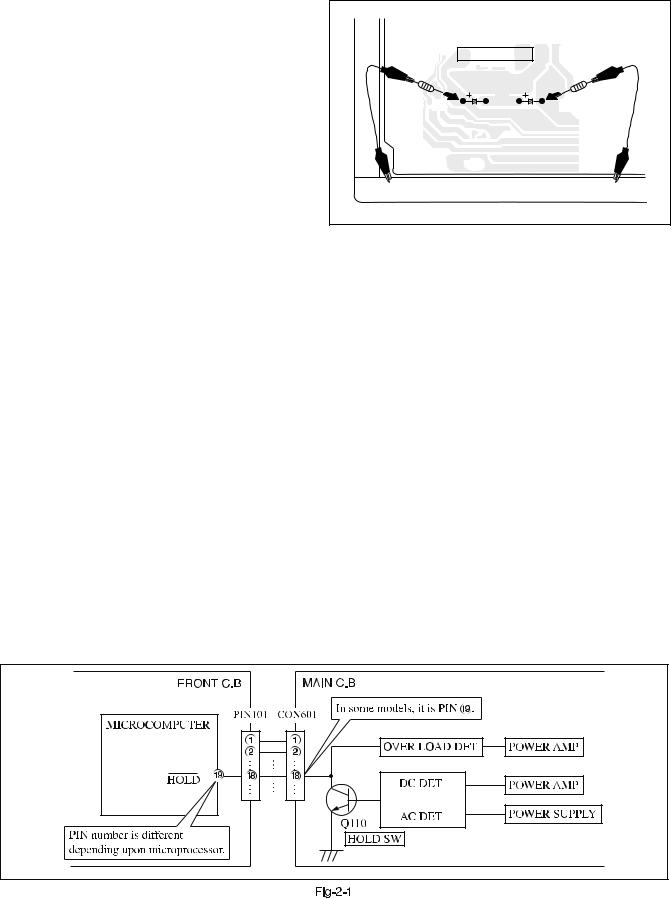
2. Check items before exchanging the MICROCOMPUTER
Be sure to check the following items before exchanging the MICROCOMPUTER. Exchange the MICROCOMPUTER after confirming that the MICROCOMPUTER is surely defective.
2-1. Regarding the HOLD terminal of the MICROCOMPUTER
When the HOLD terminal (INPUT) of the MICROCOMPUTER is “H”, the MICROCOMPUTER is judged to be operating correctly. When this terminal is “L”, the main power cannot be turned on. Therefore, be sure to check the terminal voltage of the HOLD terminal before exchange.
When the MICROCOMPUTER is not defective, the HOLD terminal can also go “L” when the POWER AMPLIFIER has any abnormalities that triggers the abnormality detection circuit on the MAIN C. B. that sets the HOLD terminal to “L”.
•Good or no good judgement of the MICROCOMPUTER
1 Turn on the AC main power.
2 Confirm that the main power is turned on and the HOLD terminal of the MICROCOMPUTER keeps the “H” level or not. 3 When the HOLD terminal is “L” level, the abnormality detection circuit is judged to be working correctly and the
MICROCOMPUTER is judged to be good.
– 4 – |
In such a case, check also if the POWER AMPLIFIER circuit or power supply circuit has any abnormalities or not.
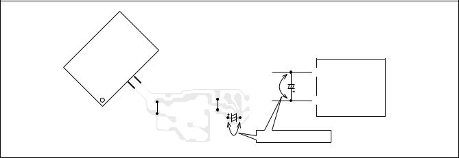
2-2. Regarding reset
There are cases that the machine does not work correctly because the MICROCOMPUTER is not reset even though the AC power cord is re-inserted, or the software reset (pressing the STOP key + POWER key) is performed.
When the above described phenomenon occurs, it can lead to wrong judgement as if the MICROCOMPUTER is defective and to exchange the MICROCOMPUTER. In such a case, perform the forced-reset by the following procedure and check good or no good of the MICROCOMPUTER.
1 Remove the AC power cord.
MICROCOMPUTER |
|
MICRO- |
|
|
FRONT C.B |
18 |
%VSS |
|
15 |
C113 |
|
|
COMPUTER |
|
|
|
|
|
*VDD |
|
|
C113 |
|
FRONT C.B |
|
|
|
Short with tweezers. |
|
Fig-2-2
2Short both ends of the electrolytic capacitor C113 that is connected to VDD of the MICROCOMPUTER with tweezers.
3Connect the AC power cord again. If the MICROCOMPUTER returns to the normal operation, the MICROCOMPUTER is good.
Note: The reference number or MICROCOMPUTER pin number of transistor (Q110) and electrolytic capacitor (C113) can change depending on the models. Be sure to check the reference numbers on schematic diagram before starting the discharging work.
2-3. Confirmation of soldering state of MICROCOMPUTER
Check the soldering state of the MICROCOMPUTER in addition to the above described procedures. Be sure to exchange the MICROCOMPUTER after surely confirming that the trouble is not caused by poor soldering but the MICROCOMPUTER itself.
– 5 –
ELECTRICAL MAIN PARTS LIST
REF. NO. |
PART NO. |
KANRI |
DESCRIPTION |
REF. NO. |
PART NO. |
KANRI |
DESCRIPTION |
||
|
|
NO. |
|
|
|
NO. |
|
|
|
IC |
|
|
|
C36 |
87-010-381-080 |
CAP, ELECT |
330-16V |
||
|
|
|
|
C38 |
87-A11-567-080 |
C-CAP,S 0.01-50 K B |
|||
|
8A-NFA-615-010 |
C-IC,M38B57MCH-E236FP |
C60 |
87-010-403-080 |
CAP, ELECT |
3.3-50V |
|||
|
87-A21-397-010 |
IC,STK490-070 |
C97 |
87-010-196-080 |
CHIP CAPACITOR,0.1-25 |
||||
|
87-A21-629-010 |
IC,SPS-442-1-N |
C100 |
87-018-127-080 |
CAP TC-U 470P |
|
|||
|
87-A21-419-040 |
C-IC,NJM14558MD-TE2 |
|
|
|
|
|
|
|
|
87-A21-443-040 |
C-IC,M62495AFP |
C101 |
87-010-183-080 |
C-CAP,S 2700P-50 B |
||||
|
|
|
|
C102 |
87-010-183-080 |
C-CAP,S 2700P-50 B |
|||
|
87-A21-415-010 |
IC,LA1843 |
C103 |
87-010-545-080 |
CAP, ELECT |
0.22-50V |
|||
|
87-070-127-110 |
IC,LC72131 D |
C104 |
87-010-545-080 |
CAP, ELECT |
0.22-50V |
|||
|
|
|
|
C105 |
87-010-178-080 |
CHIP CAP 1000P |
|
||
TRANSISTOR |
|
|
|
C106 |
87-010-178-080 |
CHIP CAP 1000P |
|
||
|
|
|
|
C107 |
87-010-404-080 |
CAP, ELECT |
4.7-50V |
||
|
87-026-609-080 |
TR,KTA1266GR |
C108 |
87-010-404-080 |
CAP, ELECT |
4.7-50V |
|||
|
89-213-702-010 |
TR,2SB1370 (1.8W) |
C111 |
87-010-391-080 |
CAP,E 10-35 SME |
|
|||
|
87-026-610-080 |
TR,KTC3198GR |
C112 |
87-010-391-080 |
CAP,E 10-35 SME |
|
|||
|
87-A30-076-080 |
C-TR,2SC3052F |
|
|
|
|
|
|
|
|
87-A30-075-080 |
C-TR,2SA1235F |
C113 |
87-010-405-080 |
CAP, ELECT |
10-50V |
|||
|
|
|
|
C114 |
87-010-405-080 |
CAP, ELECT |
10-50V |
||
|
87-026-245-080 |
TR,DTC114ES<LH> |
C119 |
87-010-197-080 |
CAP, CHIP 0.01 |
DM |
|||
|
87-A30-198-080 |
TR,KTC3199GR<LH> |
C120 |
87-010-197-080 |
CAP, CHIP 0.01 |
DM |
|||
|
87-A30-090-080 |
FET,2SK2541 |
C125 |
87-012-368-080 |
C-CAP,S 0.1-50 |
F |
|||
|
87-A30-484-080 |
C-TR,KRA102S |
|
|
|
|
|
|
|
|
87-A30-468-080 |
C-TR,KRC102S-RTK |
C126 |
87-012-368-080 |
C-CAP,S 0.1-50 |
F |
|||
|
|
|
|
C127 |
87-012-368-080 |
C-CAP,S 0.1-50 |
F |
||
|
87-A30-107-070 |
C-TR,CMBT5401 |
C128 |
87-012-368-080 |
C-CAP,S 0.1-50 |
F |
|||
|
87-A30-106-040 |
C-TR,CMBT5551 |
C129 |
87-A11-572-080 |
C-CAP,S 0.015-50 K B |
||||
|
87-A30-091-080 |
FET,2SJ460 |
C130 |
87-A11-572-080 |
C-CAP,S 0.015-50 K B |
||||
|
87-A30-062-080 |
C-TR,KRC104S |
|
|
|
|
|
|
|
|
87-A30-318-080 |
TR,CSA952K |
C131 |
87-010-197-080 |
CAP, CHIP 0.01 |
DM |
|||
|
|
|
|
C132 |
87-010-197-080 |
CAP, CHIP 0.01 |
DM |
||
|
89-333-317-880 |
TR,2SC3331 (0.5W) |
C133 |
87-010-186-080 |
CAP,CHIP 4700P |
|
|||
|
87-A30-234-080 |
TR,CSC4115BC |
C140 |
87-010-182-080 |
C-CAP,S 2200P-50 B |
||||
|
89-327-143-080 |
TR,2SC2714 (0.1W) |
C183 |
87-010-387-080 |
CAP,E 470-25 SME<U> |
||||
|
87-A30-489-080 |
C-TR,KRA107S |
C200 |
87-018-195-080 |
CAP TC-U 1200P |
|
|||
|
|
|
|
|
|||||
|
|
|
|
C235 |
87-010-408-080 |
CAP, ELECT 47-50V<U> |
|||
DIODE |
|
|
|
C236 |
87-010-408-080 |
CAP, ELECT 47-50V<U> |
|||
|
|
|
|
C300 |
87-018-195-080 |
CAP TC-U 1200P |
|
||
|
87-020-465-080 |
DIODE,1SS133 (110MA) |
C301 |
87-010-179-080 |
CAP,CHIP S B1200P |
||||
|
87-A40-393-090 |
DIODE,1N5402GW(F20)<U> |
|
|
|
|
|
|
|
|
87-A40-455-080 |
DIODE,RL203 GW |
C302 |
87-010-179-080 |
CAP,CHIP S B1200P |
||||
|
87-A40-553-080 |
DIODE,1N4003 LES |
C303 |
87-010-178-080 |
CHIP CAP 1000P |
|
|||
|
87-A40-774-080 |
ZENER,UZ24BSD |
C304 |
87-010-178-080 |
CHIP CAP 1000P |
|
|||
|
|
|
|
C305 |
87-010-198-080 |
CAP, CHIP 0.022 |
|
||
|
87-A40-764-080 |
ZENER,UZ10BSC |
C307 |
87-010-263-080 |
CAP, ELECT |
100-10V |
|||
|
87-A40-313-080 |
C-DIODE,MC 2840 |
|
|
|
|
|
|
|
|
87-A40-270-080 |
C-DIODE,MC2838 |
C308 |
87-010-263-080 |
CAP, ELECT |
100-10V |
|||
|
87-A40-269-080 |
C-DIODE,MC2836 |
C311 |
87-010-598-080 |
C-CAP,S 0.068-16VRK |
||||
|
87-A40-768-080 |
ZENER,UZ16BSA |
C312 |
87-010-598-080 |
C-CAP,S 0.068-16VRK |
||||
|
|
|
|
C313 |
87-010-188-080 |
CAP,CHIP 6800P |
|
||
|
87-A40-752-080 |
ZENER,UZ6.2BSC |
C314 |
87-010-188-080 |
CAP,CHIP 6800P |
|
|||
|
87-A40-739-080 |
ZENER,UZ2.7BSA |
|
|
|
|
|
|
|
|
87-017-149-080 |
ZENER,HZS6A2L |
C315 |
87-010-263-080 |
CAP, ELECT |
100-10V |
|||
|
|
|
|
C317 |
87-010-546-080 |
CAP, ELECT |
0.33-50V |
||
|
|
|
|
C318 |
87-010-546-080 |
CAP, ELECT |
0.33-50V |
||
MAIN C.B |
|
|
|
C326 |
87-010-198-080 |
CAP, CHIP 0.022 |
|
||
C3 |
87-010-196-080 |
CHIP CAPACITOR,0.1-25 |
C327 |
87-010-196-080 |
CHIP CAPACITOR,0.1-25 |
||||
|
|
|
|
|
|
||||
C4 |
87-010-196-080 |
CHIP CAPACITOR,0.1-25 |
C360 |
87-010-401-080 |
CAP, ELECT |
1-50V |
|||
C5 |
87-010-196-080 |
CHIP CAPACITOR,0.1-25 |
C399 |
87-012-140-080 |
CAP 470P |
|
|
|
|
C6 |
87-010-196-080 |
CHIP CAPACITOR,0.1-25 |
C401 |
87-010-544-080 |
CAP, ELECT |
0.1-50V |
|||
C9 |
87-010-196-080 |
CHIP CAPACITOR,0.1-25 |
C402 |
87-010-544-080 |
CAP, ELECT |
0.1-50V |
|||
C10 |
87-010-196-080 |
CHIP CAPACITOR,0.1-25 |
C405 |
87-010-197-080 |
CAP, CHIP 0.01 |
DM |
|||
|
|
|
|
|
|
||||
C11 |
87-010-196-080 |
CHIP CAPACITOR,0.1-25 |
C406 |
87-010-197-080 |
CAP, CHIP 0.01 |
DM |
|||
C12 |
87-010-196-080 |
CHIP CAPACITOR,0.1-25 |
C407 |
87-010-197-080 |
CAP, CHIP 0.01 |
DM |
|||
C19 |
87-A10-627-000 |
CAP,E 2200-50 M SMG |
C408 |
87-010-197-080 |
CAP, CHIP 0.01 |
DM |
|||
C20 |
87-A10-627-000 |
CAP,E 2200-50 M SMG |
C409 |
87-010-182-080 |
C-CAP,S 2200P-50 B |
||||
C21 |
87-016-495-000 |
CAP,E 3300-25 M SMG |
C410 |
87-010-182-080 |
C-CAP,S 2200P-50 B |
||||
|
|
|
|
|
|
||||
C22 |
87-016-495-000 |
CAP,E 3300-25 M SMG |
C411 |
87-010-405-080 |
CAP, ELECT |
10-50V |
|||
C25 |
87-010-385-080 |
CAP, ELECT 220-25V |
C412 |
87-010-405-080 |
CAP, ELECT |
10-50V |
|||
C26 |
87-010-247-080 |
CAP, ELECT 100-50V |
C452 |
87-010-382-080 |
CAP, ELECT |
22-25V |
|||
C30 |
87-010-247-080 |
CAP, ELECT 100-50V |
C453 |
87-010-183-080 |
C-CAP,S 2700P-50 B |
||||
C31 |
87-010-263-080 |
CAP, ELECT 100-10V |
C454 |
87-010-183-080 |
C-CAP,S 2700P-50 B |
||||
|
|
|
|
|
|
||||
C32 |
87-010-197-080 |
CAP, CHIP 0.01 DM |
C455 |
87-010-183-080 |
C-CAP,S 2700P-50 B |
||||
C33 |
87-010-263-080 |
CAP, ELECT 100-10V<U> |
C456 |
87-010-197-080 |
CAP, CHIP 0.01 |
DM |
|||
C34 |
87-010-247-080 |
CAP, ELECT 100-50V |
C460 |
87-010-196-080 |
CHIP CAPACITOR,0.1-25 |
||||
C35 |
87-010-406-080 |
CAP, ELECT 22-50 |
C461 |
87-012-158-080 |
C-CAP,S 390P-50 CH |
||||
|
|
|
|
C462 |
87-012-158-080 |
C-CAP,S 390P-50 CH |
|||
– 6 –
REF. NO. |
PART NO. |
C605 |
87-010-179-080 |
C606 |
87-010-179-080 |
C609 |
87-010-213-080 |
C610 |
87-010-213-080 |
C611 |
87-010-545-080 |
C612 |
87-010-545-080 |
C613 |
87-010-545-080 |
C614 |
87-010-545-080 |
C615 |
87-010-154-080 |
C616 |
87-010-385-080 |
C617 |
87-010-385-080 |
C618 |
87-010-405-080 |
C630 |
87-016-669-080 |
C669 |
87-010-322-080 |
C670 |
87-010-322-080 |
C677 |
87-010-197-080 |
C771 |
87-010-263-080 |
C772 |
87-010-197-080 |
C782 |
87-010-197-080 |
C783 |
87-010-197-080 |
C784 |
87-010-197-080 |
C785 |
87-010-197-080 |
C786 |
87-010-197-080 |
C788 |
87-010-149-080 |
C789 |
87-A12-052-080 |
C790 |
87-A12-052-080 |
C791 |
87-010-196-080 |
C792 |
87-010-197-080 |
C793 |
87-010-404-080 |
C795 |
87-010-197-080 |
C796 |
87-010-197-080 |
C797 |
87-010-405-080 |
C798 |
87-010-197-080 |
C799 |
87-010-407-080 |
C800 |
87-012-369-080 |
C801 |
87-010-403-080 |
C802 |
87-012-369-080 |
C803 |
87-010-198-080 |
C804 |
87-010-263-080 |
C807 |
87-010-400-080 |
C808 |
87-010-401-080 |
C809 |
87-010-401-080 |
C810 |
87-010-196-080 |
C814 |
87-010-197-080 |
C815 |
87-010-403-080 |
C816 |
87-010-403-080 |
C821 |
87-010-405-080 |
C823 |
87-010-177-080 |
C824 |
87-010-405-080 |
C825 |
87-010-596-080 |
C842 |
87-010-197-080 |
C844 |
87-010-197-080 |
C851 |
87-010-197-080 |
C852 |
87-010-197-080 |
C853 |
87-010-197-080 |
C858 |
87-010-196-080 |
C859 |
87-010-196-080 |
C860 |
87-010-197-080 |
C959 |
87-010-196-080 |
C960 |
87-010-196-080 |
C961 |
87-010-152-080 |
C963 |
87-015-785-080 |
C971 |
87-010-381-080 |
C972 |
87-010-404-080 |
C973 |
87-010-197-080 |
C974 |
87-010-197-080 |
C979 |
87-010-322-080 |
C982 |
87-010-196-080 |
C983 |
87-010-197-080 |
C984 |
87-010-197-080 |
KANRI |
DESCRIPTION |
NO. |
|
CAP,CHIP S B1200P
CAP,CHIP S B1200P
C-CAP,S 0.015-50 B
C-CAP,S 0.015-50 B
CAP, ELECT 0.22-50V
CAP, ELECT 0.22-50V
CAP, ELECT 0.22-50V
CAP, ELECT 0.22-50V
CAP CHIP 10P
CAP, ELECT 220-25V
CAP, ELECT 220-25V
CAP, ELECT 10-50V
C-CAP,S 0.1-25 K B
C-CAP,S 100P-50 CH
C-CAP,S 100P-50 CH
CAP, CHIP 0.01 DM
CAP, ELECT 100-10V
CAP, CHIP 0.01 DM
CAP, CHIP 0.01 DM
CAP, CHIP 0.01 DM
CAP, CHIP 0.01 DM
CAP, CHIP 0.01 DM
CAP, CHIP 0.01 DM
C-CAP,S 5P-50 CH
C-CAP,S 0.033-25 J B
C-CAP,S 0.033-25 J B
CHIP CAPACITOR,0.1-25
CAP, CHIP 0.01 DM
CAP, ELECT 4.7-50V
CAP, CHIP 0.01 DM
CAP, CHIP 0.01 DM
CAP, ELECT 10-50V
CAP, CHIP 0.01 DM
CAP, ELECT 33-50V
C-CAP,S 0.047-50F
CAP, ELECT 3.3-50V
C-CAP,S 0.047-50F
CAP, CHIP 0.022
CAP, ELECT 100-10V
CAP, ELECT 0.47-50V
CAP, ELECT 1-50V
CAP, ELECT 1-50V
CHIP CAPACITOR,0.1-25
CAP, CHIP 0.01 DM
CAP, ELECT 3.3-50V
CAP, ELECT 3.3-50V
CAP, ELECT 10-50V
C-CAP,S 820P-50 SL
CAP, ELECT 10-50V
CAP, S 0.047-16
CAP, CHIP 0.01 DM
CAP, CHIP 0.01 DM
CAP, CHIP 0.01 DM
CAP, CHIP 0.01 DM
CAP, CHIP 0.01 DM
CHIP CAPACITOR,0.1-25
CHIP CAPACITOR,0.1-25
CAP, CHIP 0.01 DM
CHIP CAPACITOR,0.1-25
CHIP CAPACITOR,0.1-25
C-CAP,S 8P-50 CH
CHIP CAPACITOR, 0.1FZ-25Z CAP, ELECT 330-16V
CAP, ELECT 4.7-50V
CAP, CHIP 0.01 DM
CAP, CHIP 0.01 DM
C-CAP,S 100P-50 CH
CHIP CAPACITOR,0.1-25
CAP, CHIP 0.01 DM
CAP, CHIP 0.01 DM
REF. NO. |
PART NO. |
KANRI |
DESCRIPTION |
|
|
NO. |
|
C987 |
87-010-197-080 |
CAP, CHIP 0.01 DM |
|
C993 |
87-010-178-080 |
CHIP CAP 1000P |
|
C995 |
87-010-178-080 |
CHIP CAP 1000P |
|
C997 |
87-010-196-080 |
CHIP CAPACITOR,0.1-25 |
|
C999 |
87-A11-155-080 |
CAP,TC U 0.01-16 Z F |
|
CF831 |
87-008-261-010 |
FILTER, SFE10.7MA5-A |
|
CF832 |
87-008-261-010 |
FILTER, SFE10.7MA5-A |
|
CN301 |
87-A60-620-010 |
CONN,3P V 2MM JMT |
|
CN351 |
87-A60-625-010 |
CONN,8P V 2MM JMT |
|
CN601 |
87-099-719-010 |
CONN,30P TYK-B(X) |
|
CN602 |
87-099-194-010 |
CONN,6P 6216V |
|
CNA1 |
8A-NF8-653-010 |
CONN ASSY,9P TID-A(480)<LH> |
|
FFE831 |
A8-8ZA-190-030 |
8ZA-1 FEUNM |
|
J101 |
87-A60-602-010 |
JACK,DIA6.3 BLK ST W/SW TC |
|
J203 |
87-A60-238-010 |
TERMINAL,SP 4P (MSC) |
|
J205 |
87-A60-881-010 |
JACK,PIN 2P MSP 242V05 PBSN<U> |
|
J602 |
87-A60-881-010 |
JACK,PIN 2P MSP 242V05 PBSN |
|
J831 |
87-A60-202-010 |
TERMINAL,ANT 4P MSP-154V-02 |
|
L101 |
87-003-383-010 |
COIL,1UH-S |
|
L102 |
87-003-383-010 |
COIL,1UH-S |
|
L451 |
87-007-342-010 |
COIL,OSC 85K BIAS |
|
L801 |
87-A50-540-010 |
COIL,FM DET (TOK) |
|
L802 |
87-A91-551-010 |
FLTR,PCFJZH-450 L(TOK) |
|
L811 |
87-005-847-080 |
COIL,2.2UH(CECS) |
|
L832 |
87-005-847-080 |
COIL,2.2UH(CECS) |
|
L951 |
8A-NF8-667-010 |
COIL,AM PACK 4(TOK) |
|
R131 |
87-A00-258-080 |
RES,M/F 0.22-1W J<LH> |
|
R131 |
87-A00-669-080 |
RES,M/F 0.22-2W J RA<U> |
|
R132 |
87-A00-258-080 |
RES,M/F 0.22-1W J<LH> |
|
R132 |
87-A00-669-080 |
RES,M/F 0.22-2W J RA<U> |
|
R653 |
87-A11-144-080 |
CAP,TC U 0.1-50 K B |
|
R654 |
87-A11-144-080 |
CAP,TC U 0.1-50 K B |
|
R790 |
87-010-197-080 |
CAP, CHIP 0.01 DM |
|
R991 |
87-010-322-080 |
C-CAP,S 100P-50 CH |
|
R993 |
87-010-322-080 |
C-CAP,S 100P-50 CH |
|
R995 |
87-010-322-080 |
C-CAP,S 100P-50 CH |
|
WH1 |
87-A90-510-010 |
HLDR,WIRE 2.5-9P |
|
X991 |
87-A70-061-010 |
VIB,XTAL 4.500MHZ CSA-309 |
|
FRONT C.B |
|
|
|
C101 |
87-010-196-080 |
CHIP CAPACITOR,0.1-25 |
|
C102 |
87-012-369-080 |
C-CAP,S 0.047-50F |
|
C103 |
87-010-374-040 |
CAP, ELECT 47-10 |
|
C104 |
87-A10-797-040 |
CAP,E 47-35 M 5L SRM |
|
C105 |
87-010-192-080 |
C-CAP,S 0.022-50 F |
|
C107 |
87-010-196-080 |
CHIP CAPACITOR,0.1-25 |
|
C108 |
87-010-178-080 |
CHIP CAP 1000P |
|
C109 |
87-012-369-080 |
C-CAP,S 0.047-50F |
|
C110 |
87-010-197-080 |
CAP, CHIP 0.01 DM |
|
C111 |
87-010-196-080 |
CHIP CAPACITOR,0.1-25 |
|
C113 |
87-010-178-080 |
CHIP CAP 1000P |
|
C114 |
87-010-154-080 |
CAP CHIP 10P |
|
C115 |
87-010-175-080 |
CAP 560P |
|
C116 |
87-010-400-040 |
CAP,E 0.47-50 |
|
C117 |
87-016-460-080 |
C-CAP,S 0.22-16 B |
|
C118 |
87-A10-189-040 |
CAP,E 220-10 |
|
C119 |
87-A10-189-040 |
CAP,E 220-10 |
|
C120 |
87-012-156-080 |
C-CAP,S 220P-50 CH |
|
C123 |
87-010-196-080 |
CHIP CAPACITOR,0.1-25 |
|
C124 |
87-010-196-080 |
CHIP CAPACITOR,0.1-25 |
|
C125 |
87-010-405-040 |
CAP,E 10-50 |
|
C126 |
87-010-196-080 |
CHIP CAPACITOR,0.1-25 |
|
C129 |
87-010-374-040 |
CAP,E 47-10 |
|
C210 |
87-012-156-080 |
C-CAP,S 220P-50 CH |
|
C212 |
87-010-404-040 |
CAP,E 4.7-50 SME |
|
C213 |
87-010-404-040 |
CAP,E 4.7-50 SME |
|
C701 |
87-010-384-040 |
CAP,E 100-25 SME |
|
CN101 |
87-099-720-010 |
CONN,30P TYK-B(P) |
|
CN701 |
87-A60-673-010 |
CONN,9P H 2MM JMT |
|
– 7 –

REF. NO. PART NO.
CN801 87-099-015-010 FL201 8A-NFA-604-010 L101 87-A50-050-010 LED101 87-A40-317-080 S101 87-A91-555-010
S301 87-A90-164-080
S302 87-A90-164-080
S303 87-A90-164-080
S304 87-A90-164-080
S305 87-A90-164-080
S306 87-A90-164-080
S307 87-A90-164-080
S308 87-A90-164-080
S309 87-A90-164-080
S321 87-A90-164-080
S322 87-A90-164-080
S323 87-A90-164-080
S324 87-A90-164-080
S325 87-A90-164-080
S326 87-A90-164-080
S327 87-A90-164-080
S328 87-A90-164-080
S329 87-A90-164-080
S330 87-A90-164-080
S331 87-A90-164-080
SFR701 87-024-431-080
KANRI |
DESCRIPTION |
NO. |
|
CONN,13P 6216V
FL,10-BT-224GNK COIL,CLK 4.19M(COI) LED,SLR-342VCT31 RED SW,RTRY EC12E24504
SW,TACT SKQAB(N)
SW,TACT SKQAB(N)
SW,TACT SKQAB(N)
SW,TACT SKQAB(N)
SW,TACT SKQAB(N)
SW,TACT SKQAB(N)
SW,TACT SKQAB(N)
SW,TACT SKQAB(N)
SW,TACT SKQAB(N)
SW,TACT SKQAB(N)
SW,TACT SKQAB(N)
SW,TACT SKQAB(N)
SW,TACT SKQAB(N)
SW,TACT SKQAB(N)
SW,TACT SKQAB(N)
SW,TACT SKQAB(N)
SW,TACT SKQAB(N)
SW,TACT SKQAB(N)
SW,TACT SKQAB(N)
SW,TACT SKQAB(N)
SFR,3.3K RH063EC
|
REF. NO. |
PART NO. |
KANRI |
DESCRIPTION |
|
|
|
NO. |
|
|
PT C.B |
|
|
|
|
C1 |
87-010-387-080 |
CAP,E 470-25 SME<LH> |
|
|
C31 |
87-010-403-080 |
CAP, ELECT 3.3-50V<LH> |
|
|
C184 |
87-010-403-080 |
CAP, ELECT 3.3-50V<U> |
|
|
CN1 |
87-A61-110-010 |
CONN,9P V TID-A<LH> |
|
! |
PT1 |
8A-NFA-609-010 |
PT,ANF-A LH<LH> |
|
! |
PT1 |
8A-NFZ-610-010 |
PT,ANF-Z U30<U> |
|
! |
PT2 |
8A-NF8-673-010 |
PT,SUB ANF-8 (H)KAMI<LH> |
|
! |
PT181 |
8A-NF8-661-010 |
PT,SUB ANF-8 (U)<U> |
|
! |
RY1 |
87-A91-281-010 |
RELAY,AC DC12V OSA-SS-212DM5<LH> |
|
! |
RY181 |
87-A90-976-010 |
RELAY,AC12V SDT-S-112LMR<U> |
|
! |
S1 |
87-A90-165-010 |
SW,SL 1-2-3 SWS2301<LH> |
|
! |
T1 |
87-A60-317-010 |
TERMINAL, 1P MSC<LH> |
|
! |
T2 |
87-A60-317-010 |
TERMINAL, 1P MSC<LH> |
|
! |
T181 |
87-A60-317-010 |
TERMINAL, 1P MSC<U> |
|
! |
T182 |
87-A60-317-010 |
TERMINAL, 1P MSC<U> |
|
|
W99 |
8A-NF9-609-010 |
F-CABLE,9P 2.5 480MM<U> |
|
|
WH181 |
87-A90-510-010 |
HLDR,WIRE 2.5-9P<U> |
|
 CHIP RESISTOR PART CODE
Chip Resistor Part Coding
8 8
A
Figure
Resistor Code
Value of resistor
Chip resistor
Wattage |
Type |
Tolerance |
Symbol |
Dimensions (mm) |
|
: A |
||
Form |
L |
W |
t |
Resistor Code : A |
||||
1/16W |
1005 |
5% |
CJ |
|
1.0 |
0.5 |
0.35 |
104 |
1/16W |
1608 |
5% |
CJ |
L |
1.6 |
0.8 |
0.45 |
108 |
t |
||||||||
1/10W |
2125 |
5% |
CJ |
W |
2 |
1.25 |
0.45 |
118 |
1/8W |
3216 |
5% |
CJ |
|
3.2 |
1.6 |
0.55 |
128 |
– 8 –
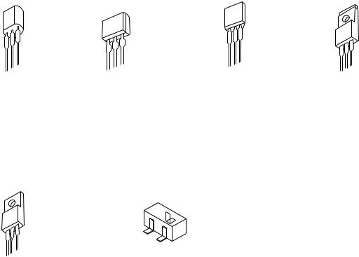
TRANSISTOR ILLUSTRATION
E C B |
S D G |
E C B |
B C E |
CSA952 |
2SJ460 |
DTC114ES |
2SB1370 |
CSC4115 |
2SK2541 |
|
|
KTA1266 |
|
|
|
KTC3198 |
|
|
|
KTC3199 |
|
|
|
C
B
E
B C E |
|
|
2SC3331 |
2SA1235 |
KRA102 |
|
2SC2714 |
KRA107 |
|
2SC3052 |
KRC102 |
|
CMBT5401 |
KRC104 |
|
CMBT5551 |
|
– 9 –

FL (10-BT-224GNK) GRID ASSIGNMENT & ANODE CONNECTION
GRID ASSIGNMENT
– 10 –
 Loading...