

Page 1
NC3600 P4LRH
English
SERVICE MANUAL
VIDEO MECHANISM
S/M Code No. 09-995-333-1N1
DATA
Page 2

VCR TEST TAPE INTERCHANGEABILITY TABLE
There are two types of the new allgnment tape CH-1B (for NTSC) and CH-2 (for PAL). On each tape four signals (1)-(4)
are recorded for the times and in the order shown below.
(1) : 8min. fi (2) : 2min. fi (3) : 5min. fi (4) : 5min.
The TTV-MP1 (for M-PAL), TTV-MS1 (for MESECAM) and TTV-S1 (for SECAM) allgnment tapes have the same
contents as the previous tapes.
Method
NTSC
Now in use TYPE
Model Contents *1
TTV-N1
TTV-NS1
TTV-N1E
TTV-NS6E
TTV-N2
TTV-N12
(SCV-1998)
TTV-N6
(TTV-N06T)
TTV-N7A
NTSC, Color bar,
1kHz, SP
NTSC, Color bar,
1kHz, SP
NTSC, Color bar,
1kHz, EP
NTSC, Color bar,
No sound, EP
NTSC, Stairsteps,
7kHz, SP
NTSC, Color bar,
1kHz, SP
NTSC, Mono scope,
7kHz, SP
NTSC, Stairsteps,
1kHz, SP, HiFi 400Hz
New TYPE
Model Contents *1
CH-1B(2)
CH-1B(4)
*2
CH-1B(1)
CH-1B(4)
CH-1B(3)
NTSC, Stairsteps,
1kHz, SP
No Changed.
NTSC, Color bar,
1kHz, EP
No Changed.
NTSC, Stairsteps,
7kHz, SP
NTSC, Color bar,
1kHz, EP
No Changed.
NTSC, Color bar,
No sound SP,
HiFi 400Hz
Application
PB-Y Level/General electrical ADJ.
Head ACE Height/Tilt ADJ.
For S-VHS (SQPB) check
Switching position ADJ.
For S-VHS (SQPB) check
Head ACE Azimuth ADJ.
FM Envelope ADJ.
X-V alue ADJ.
For total picture quality check (resolution, etc)
HiFi Audio PB Level ADJ.
Switching position ADJ.
PB-Y Level/General electrical ADJ.
Head ACE Height/Tilt ADJ.
Switching position. (LP Model)
FM Envelope ADJ. (LP Model)
X-Value ADJ. (LP Model)
HEAD ACE Azimuth ADJ.
FM Envelope ADJ. (SP Model)
X-Value ADJ. (SP Model)
For total picture quality check (resolution, etc)
HiFi Audio PB Level ADJ.
FM Filter ADJ.
PAL
TTV-P1
TTV-P1L
TTV-P2
TTV-P6
(TTV-N06T)
TTV-P7
TTV-P16
PAL, Color bar,
1kHz, SP
PAL, Color bar,
1kHz, LP
PAL, Stairsteps,
6kHz, SP
PAL, Monoscope,
6kHz, SP
PAL, Stairsteps,
1kHz, SP,
HiFi 1kHz
PAL, Color bar,
400Hz,
SP, HiFi 1kHz
CH-2(2)
* 3
CH-2(4)
CH-2(1)
CH-2(3)
PAL, Stairsteps,
1kHz, SP
PAL, Color bar,
1kHz, LP
PAL, Stairsteps,
6kHz, SP
No Changed.
PAL, Color bar,
No sound
SP, HiFi400Hz
No Changed.
* 1. Described in the order of color format. video signal. linear audio. tape speed and Hi-Fi audio.
* 2. Use CH-1B (1)-(3) with models used exclusively in the SP mode.
* 3. Use CH-2 (3) and (4) when it is necessary to observe the chroma signal.
2
Page 3
Top bracket
Cassette holder
assembly
Door open lever
FL cassette
guide assembly
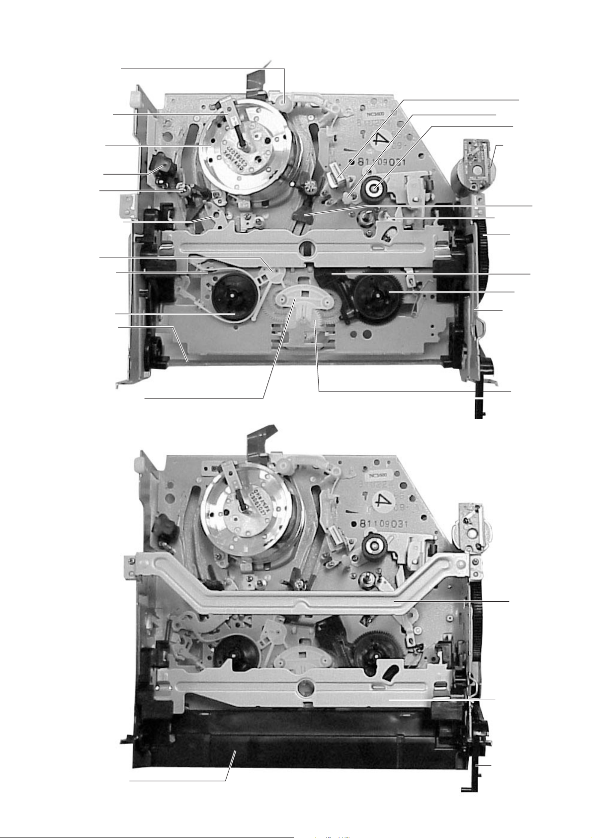
2. MECHANICAL ADJUSTMENT
2-1. LOCATION OF MECHANISM PARTS
Head cleaner
Drum brush
Cylinder
assembly
FE head
S slider
Tension lever
S brake
Band brake
ACE head
No. 8 guide cap
Pinch roller
Loading motor
T slider
No. 9 guide lever
FL cam gear
T brake
T real table
S reel table
FL arm lever
Idle lever assembly
FL drive slider
Center gear
assembly
Fig-2-1-1 Upper side
Fig-2-1-2 Upper side
3
Page 4
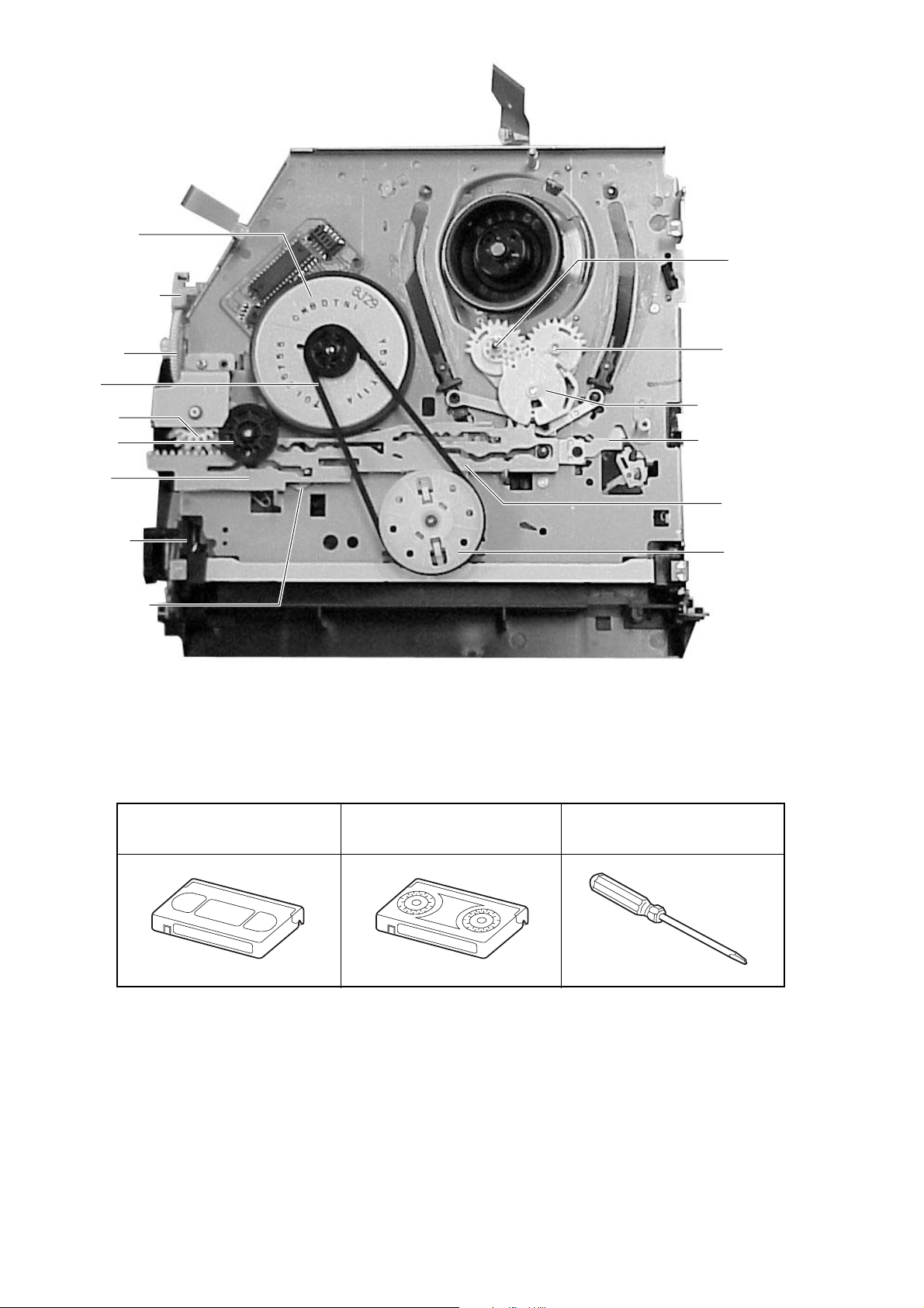
Capstan motor
Worm gear holder
T loading lever
assembly
Worm wheel
Reel belt
Joint gear 1
Joint gear 2
Cam slider
S-VHS switch
Pinch drive lever
2-2. SERVICE TOOL LIST
S loading lever
assembly
Loading drive gear
Tension drive lever
Up/down lever
Holder clutch
assembly
Fig-2-1-3 Rear side
Alignment tape
Torque cassette Post height adjustment screwdriver
(SRK-VHT-103-404) (SV-TG0-030-000)
4
Page 5

2-3. ALIGNMENT TAPES FOR ADJUSTMENT
Mechanism PAL
Adjustment item SP/LP 2/4 head
FM envelope TTV-P2L
Slant Commercially available tape
A/C head Height TTV-P1 (TTV-P1L)
Azimuth TTV-P2
X value TTV-P2 (TTV-P2L)
RG post slant Commercially available tape
Tape back-tension SRK-VHT-103
2-4. GUIDELINE OF MAJOR PARTS REPLACEMENT
• The replacement periods that are shown below, indicate the guide line only, and are the life of the individual parts.
• The following guideline is compiled on the assumption the mechanism is used under the standard operating conditions
(i.e., normal temperature and normal humidity.) The replacement periods change depending on the operating
environments, method of use and running hours.
• Life of head assembly (cylinder) is especially heavily affected by the operating conditions.
Parts name
Tension post
S/T slant guide post
Impedance roller
Guide post No. 8
Capstan
Guide post No. 9
Guide post No. 3
S/T guide roller
Tape run mechanism
Head assembly
(cylinder)
FE head
ACE head
Pinch roller
Capstan motor
Loading motor
Reel belt
Clutch gear assembly
Drive mechanismOthers
Idle lever assembly
Band brake
Slip ring assembly
500
3
3
3
3
3
3
3
3
1000
3
3
0
3
0
0
3
0
0
0
0
0
1500
3
3
0
3
0
0
3
0
0
0
0
0
Table 2-4-1
Guideline of time
2000
2500
3
3
0
0
0
0
0
0
0
0
0
0
3
3
0
0
0
0
0
0
0
0
0
0
0
0
3000
3
0
0
0
0
0
0
0
0
0
0
0
0
3500
3
0
0
0
0
0
0
0
0
0
0
0
0
4000
3
0
0
0
0
0
0
0
0
0
0
0
0
4500
3
0
0
0
0
0
0
0
0
0
0
0
0
5000
• Cleaning shall be
3
• After cleaning, wait
• Use the specified oil for
0
• When lubricating a part,
0
0
0
0
0
0
0
0
0
0
0
Remarks
performed using a
cotton swab or cotton
cloth moistened with
alcohol.
until the cleaned parts
are dried completely
before using a video
cassette tape.
lubrication.
apply only one or two
drops of oil after
cleaning the part with
alcohol.
3: Cleaning
0: Check the part. Replace when the part needs replacement.
*: Impedance roller is used in some models, but not used in some other models.
5
Page 6
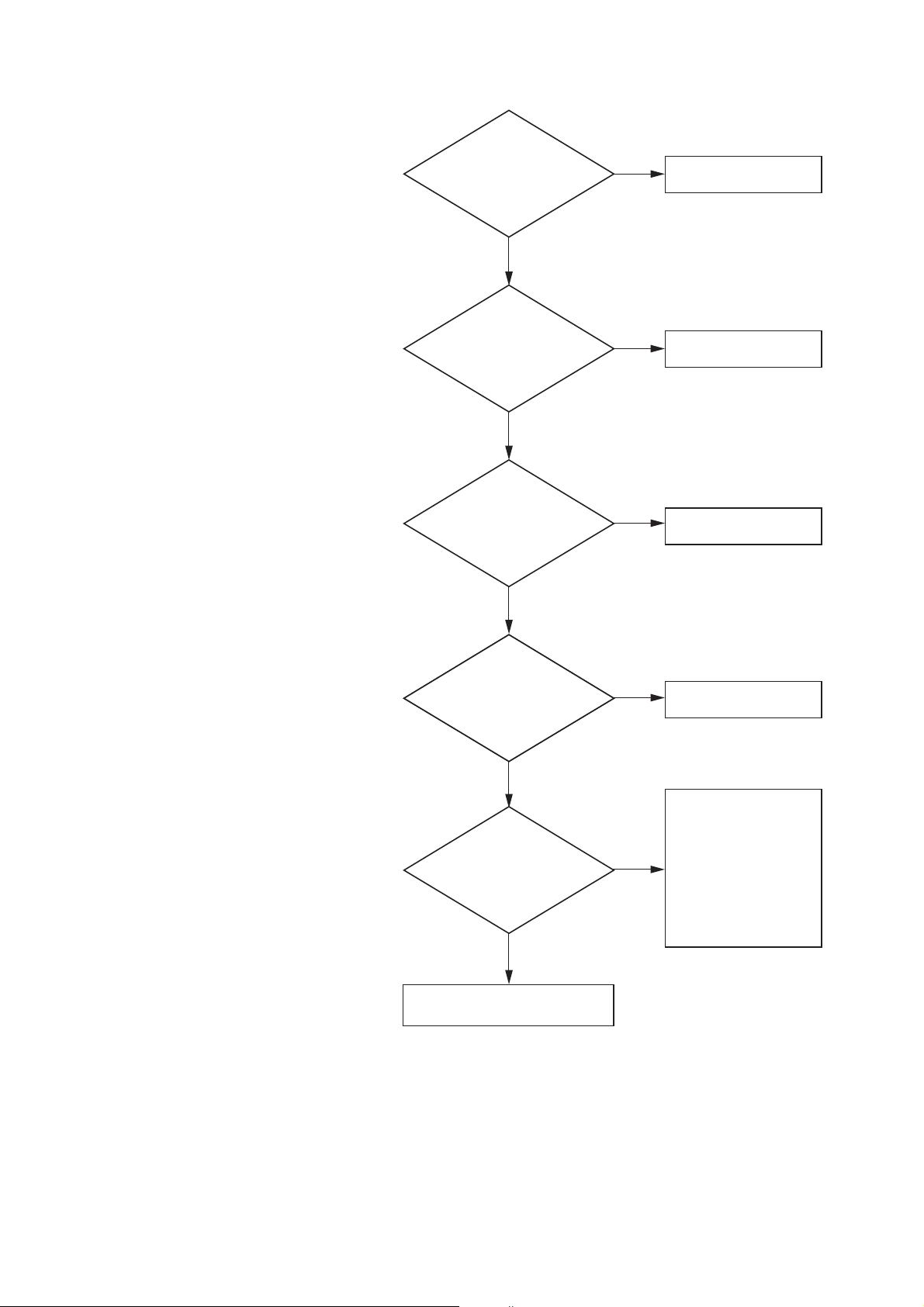
2-5. MECHANISM CHECK PROCEDURE
Do the loading motor rotate
and the worm wheel rotate
when the main power is
turned on without
inserting a cassette?
Does the FL cam gear
rotate clockwise by approx.
15 degrees and return immediately
when the above operation
is performed?
Does the capstan motor
rotate when the cassette holder
is pressed without inserting
a cassette?
Does the T reel table rotate
when the above operation
is performed?
When a cassette whose record
safety tab is not broken, is inserted,
is the tape remaining amount
displayed and is the tape
stopped at the playback
position?
Motor and sensor systems are OK.
Loading motor has
abnormality.
Tape start sensor has
abnormality.
Capstan motor has
abnormality.
Reel belt and reel system
have abnormality.
When a tape is ejected
even though it is wound up
or when tape is stopped
during unloading, the reel
sensor has abnormality.
When the mechanical
operation is found not
normal, the cam switch
has abnormality.
YES
NO
NO
NO
NO
NO
YES
YES
YES
YES
When a trouble is suspected to be caused by mechanism
from the contents of the defect symptoms, follow the
troubleshooting flow chart as shown, and locate the cause
of trouble by the procedure as shown.
2-5-1. Outside Appearance Check
1) Check if there exists any foreign materials or
not inside the VTR.
2) Check if the cylinder and the guides of the
tape run mechanism are stained or not.
2-5-2. Checking Motor and Sensors
Check if motors and sensors (including the control
circuit) have any abnormalities or not, by
following the flow chart.
2-5-3. Trouble Analysis Using the Service Mode
This model has the service mode. The service
mode provides the function to display the status
when trouble occurs. Use the service mode to
analyze cause of trouble.
Refer to the SERVICE MODE section of the
manual for the procedure to display the data and
for the contents of the service mode.
Fig-2-5-1
6
Page 7
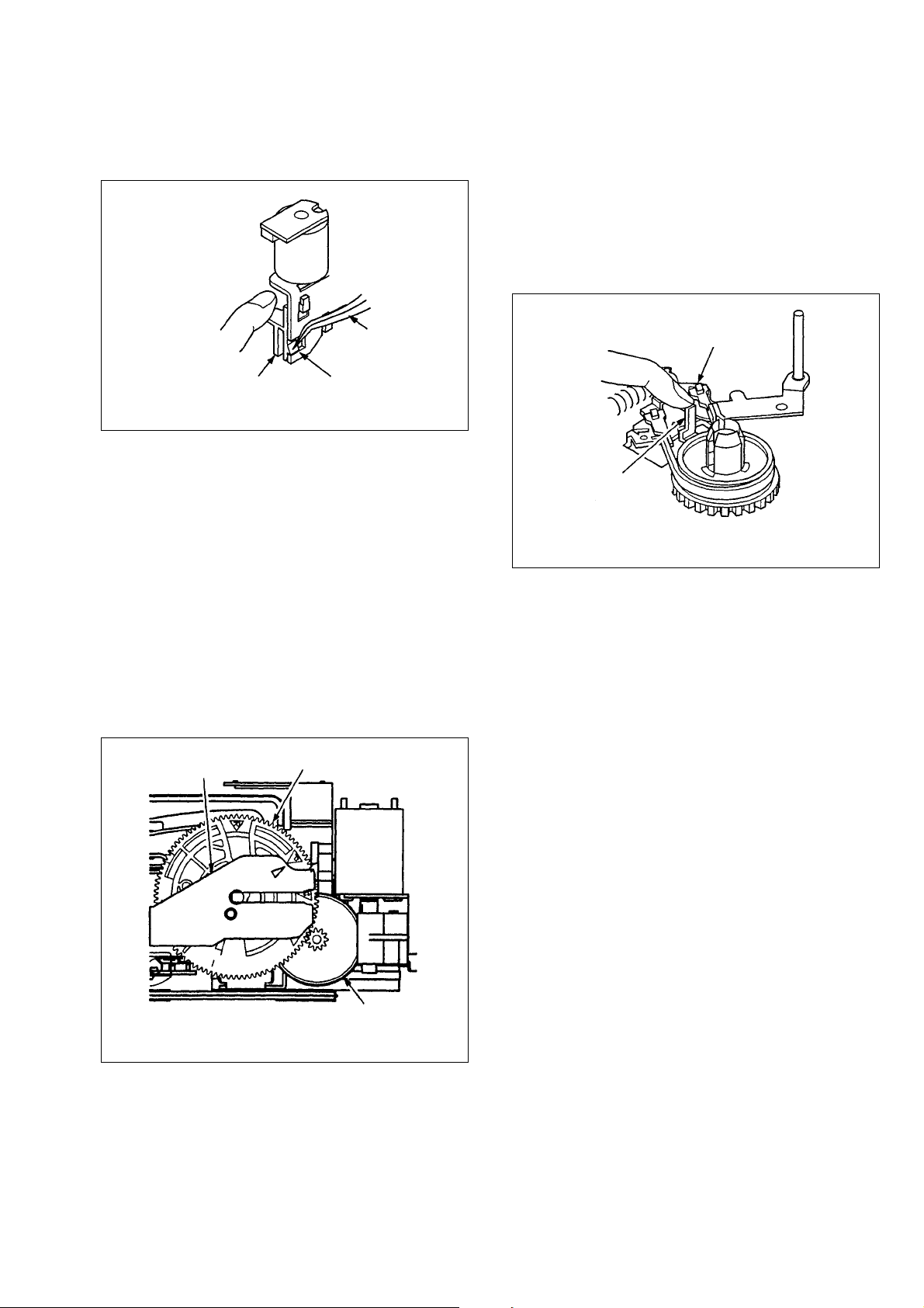
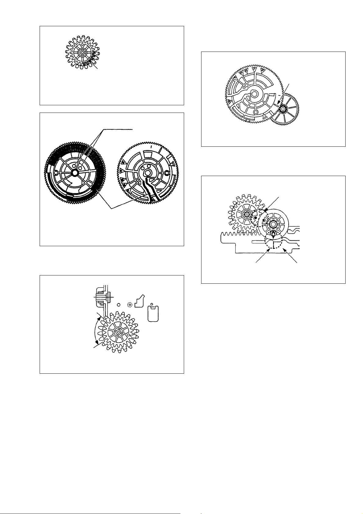
2-5-4. HOW TO OPERATE THE MECHANISM
(MODE TRANSITION) BY MANUAL
OPERATION
1) Remove the worm gear holder using tweezers
and remove the worm gear.
Note: To check the Review, Stop 2, Fast forward/Rewind
modes, rotate the mechanism I the unloading direction
and stop the mechanism where the above described marks
are aligned, and then check the mechanism.
There can be a case that the stop position of a mechanism
by the cam switch and the position where marks are
aligned, can be different due to play and variation of gear.
When you want to operate a mechanism after cassette
holder is removed, be sure to press down the tension drive
lever as shown in Fig-2-5-4 after the S and T sliders start
moving and until the T slider comes to the AC head
position.
Press it down
Worm gear holder
While pressing down the lock levers R and L of the
cassette holder by hand, rotate the worm wheel in the
clockwise direction. Then the mechanism can enter the
loading modes by manual operation.
When the triangle (3) mark of the FL drive slider and the
triangle (3) mark of the FL cam gear are aligned as
shown in Fig-2-5-3, the mechanism can enter the
following mechanism positions.
I
Power OFF
2
R
Review
2
P
Play
2
S1
Stop 1
2
FL drive slider
Press the craw down
Fig-2-5-2
S2
Stop 2
2
FR1
Fast forward/Rewind 1
2
FR2
Fast forward /Rewind 2
2
FL cam gear
Tweezers
Tension lever
Tension drive lever
Fig-2-5-4
2) On replacement of the defective parts
When a specific part is found defective and needs to
be replaced, note the following points.
• Pay special attention when replacing the mechanical
parts that need phase adjustment.
Pay special attention for the parts installation mode
and phase-alignment marks, and others.
• For the parts that need greasing and lubrication, coat
the parts with proper amount of grease or oil as
specified to the specific point. Be careful so that
grease or oil must not splashed to any other parts.
After greasing or lubrication, install the mechanism
into the product, turn on the main power and confirm
proper operation of the mechanism.
Worm wheel
Fig-2-5-3 Position mark (Play position)
Move the mechanism to the status in which the trouble
has occurred, by manual operation as shown above.
Check status of the mechanism in the status in which the
trouble has occurred.
3) Confirmation after repair work is completed.
When the repair work is completed (especially when
replacement and/or adjustment of mechanical parts
are performed), be sure to confirm operation and
movement of mechanical parts and mechanism
before installing the mechanism back into the
machine. Then turn on the main power and operate
the machine to confirm the correct operation of the
machine.
Note: When any repair work is performed and
mechanical parts are replaced in order to
solve the trouble of “Mechanical parts are
broken or phase-adjustment”, and when the
same (or similar) trouble occurs during the
operation check after the main power is
turned on, the main cause (mechanical or
electrical circuit) of the trouble may exist
in other locations. Please check the other
assemblies and blocks too.
7
Page 8
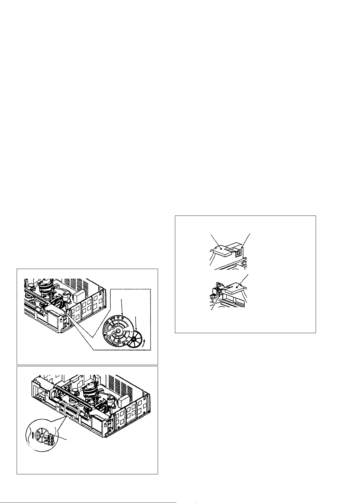
2-5-5. How To Eject A Videocassette Manually
Attach an adhesive tape
Attach an adhesive tape
Cassette retainer
block
Cassette retainer
block
Because one of the screws that fix the mechanism
deck to the chassis, is located beneath the cassette,
the mechanism deck cannot be removed while a
videocassette exists inside the mechanism deck.
If a videocassette cannot be ejected even though
the EJECT button is pressed, remove the
videocassette by the following procedure.
1) Remove the work gear holder and the worm
gear by referring to section 2-6-6. Rotate the
worm wheel in the direction of the arrow
(unloading direction, Fig-2-5-5) with a
screwdriver.
2) When the S and T sliders start unloading,
insert a precision (watch) screwdriver into the
long slot on the bottom panel as shown in Fig2-5-6 so that the loosened tape must not get
oily or must not get greasy. Using the
precision (watch) screwdriver, rotate the
pulley of the clutch gear assembly in the
direction of the arrow when viewed from the
bottom. Rotate the worm wheel to take up the
tape onto a reel table.
Note: • Stand the machine in the upright
position when removing a videocassette
manually as shown in Fig-2-5-6 and as
described in this section in order to
protect a tape.
• If a mechanism is locked and if a
videocassette cannot be ejected when
through the worm wheel is rotated,
remove by breaking the cassette
retainer block as shown in Fig-2-5-7.
2-5-6. How To Check Various Mechanism
Modes without Inserting A Videocassette
1) Attach a blind tapes on the right and left of the
cassette holder so that the sensor light should
not reach the start sensor and to the end
sensor. (Fig-2-5-7.)
2) Release both of the right and left lock levers
of the cassette holder so that the cassette
holder can be moved down and slotted in.
3) When cassette down is performed, rotating
speed of the S reel table increases. If rotation
of the S reel table is stopped, the mechanism
starts loading. (If rotation of the S reel table is
not stopped, eject will be activated.)
4) When loading is completed, rotate with hand
the reel table that is opposite side of the
presently rotating reel table.
5) In this state of mechanism, various modes can
be checked now.
Note: When the reel table that is opposite side of
the rotating reel table is turned by hand
during playback, fast forward/rewind
modes so that the reel pulse should not be
sent, the auto eject is activated or the main
power is turned off.
Front side
Rear side
When viewed form the rear side
FL cam gear
Worm
wheel
Fig-2-5-7
Fig-2-5-5
Pulley
Fig-2-5-6
8
Page 9
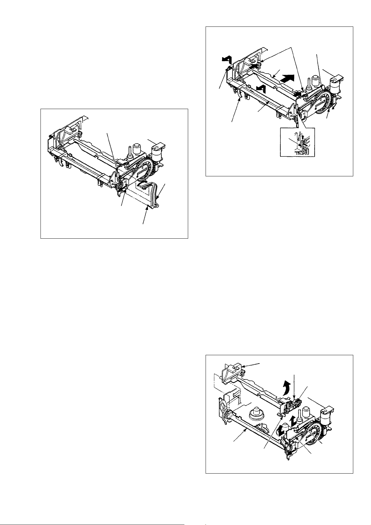
2-6. REPLACING THE MAIN PARTS
Cassette holder assembly
Lock lever
Boss A
Groove C
Groove D
Boss B
FL arm lever
2-6-1. Door Open Lever
1) Rotate the door open lever in the direction of
the arrow, and remove the claw of the door
open lever that has been inserted in the hole
on the left bottom of the right side of the
mechanism deck.
Then remove the door open lever from the
door open lever shaft and for the door open
lever guide by raising the door open lever.
Door open lever guide
Door open lever shaft
Door open
lever
Claw
FL cassette
guide assembly
Write-protection lever
(Playback only machines
do not have the writeprotection lever)
4) Replace the FL cassette guide assembly with
the new FL cassette guide assembly.
5) After the FL cassette guide assembly is
replaced, assemble the mechanism by
reversing the disassembling procedure.
Lock lever
Guide groove
Worm wheel
Claw
Fig-2-6-2
Claw
Fig-2-6-1
2) Replace the door open lever with a new door
open lever.
3) After the door open lever is replaced,
assemble the mechanism by reversing the
disassembling procedure.
Note: Attach the door open lever in a manner so
that it is located inside the guide.
2-6-2. FL Cassette Guide Assembly
1) Remove the door open lever. (Refer to 2-6-1.)
2) Press the lock levers that are located on both
sides of the cassette holder assembly and
release the lock. Move the cassette holder
assembly until it reaches the vertical shift
position of the guide groove. Remove the
lamp board in the case that your machine has a
lamp board.
Note: When the cassette holder assembly is
cannot be moved smoothly, rotate the
worm wheel clockwise.
2-6-3. Cassette Holder Assembly
1) Remove the door open lever. (Refer to 2-6-1.)
2) Remove the FL cassette guide assembly.
(Refer to Section 2-6-2.)
3) Move the cassette holder assembly to the
front.
4) Remove the cassette holder assembly from the
right side of the mechanism deck as follows:
Pull the right side of the cassette holder
assembly to the front so that the two bosses A
and B on the right side of the cassette holder
assembly, can be removed from the grooves C
and D of the mechanism deck. Then, while
releasing the lock lever in the right, raise the
cassette holder assembly obliquely and
remove the cassette holder assembly from the
right side of the mechanism deck.
3) While pressing in the craws on the both sides
of the FL cassette guide assembly inside,
remove the FL cassette assembly by raising it
up.
Fig-2-6-3
9
Page 10
5) Replace the cassette holder assembly with the
new cassette holder assembly.
6) After the cassette holder assembly is replaced,
assemble the mechanism by reversing the
disassembling procedure.
Boss of mechanism
deck
Worm wheel
FL cam gear
Note: Attach the cassette holder assembly while
releasing the lock lever.
2-6-4. FL Arm Lever
1) Remove the door open lever. (Refer to section
2-6-1.)
2) Remove the FL cassette guide assembly.
(Refer to section 2-6-2.)
3) Remove the cassette holder assembly.
(Refer to section 2-6-3.)
4) Remove the FL arm lever as follows: Pull the
left claw of the FL arm lever in the direction
of the arrow A, and remove the FL arm lever
from the boss of the mechanism deck. Pull
the FL arm lever from its left side to the front
and remove the FL arm lever.
Claw
Boss of mechanism
deck
Joint gear metal bracket
6) Turn the mechanism deck upside down.
7) Remove one screw from the joint gear metal
bracket, and remove the joint gear metal
bracket.
8) Remove the joint gear 2.
Screw
Joint gear 1
Boss hole
Screw
FL drive slider
Fig-2-6-5
Joint gear metal bracket
Boss hole
FL arm lever
FL drive slider
Boss
Fig-2-6-4
5) Replace the FL arm lever with a new FL arm
lever.
6) After the FL arm lever is replaced, assemble
the mechanism by reversing the disassembling
procedure.
Note: Attach the FL arm lever so that boss of the
FL arm lever enters into the groove of the
FL driver slider.
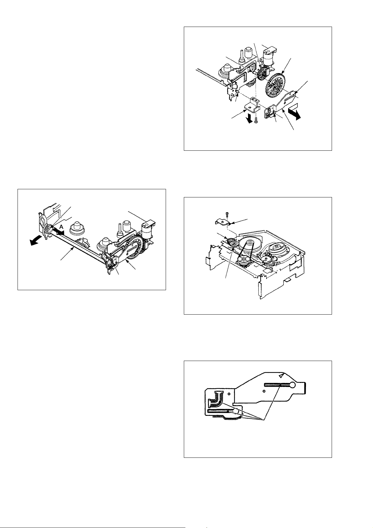
2-6-5. FL Drive Slider, Joint Gear 2, FL Cam
Gear and Joint Gear 1
1) Remove the door open lever. (Refer to section
2-6-1.)
2) Remove the FL cassette assembly. (Refer to
section 2-6-2.)
3) Remove the cassette holder assembly. (Refer
to section 2-6-3.)
4) Remove the FL arm lever. (Refer to section 26-4.)
5) Remove the FL drive slider.
Remove the FL drive slider as follows: Slide
the FL drive slider slightly to the front in order
so that the boss of the mechanism deck is
aligned to the portion where the slider groove
becomes wider (boss hole). Pull the FL drive
slider from the boss and remove the FL slider.
Joint gear 2
Fig-2-6-6
9) Remove the FL cam gear.
10) Remove the joint gear 1.
11) Replace the parts with the new parts.
Coat the following area of the new parts with
grease. (Refer to Fig-2-6-7 to Fig-2-6-11.)
The shaded portion should
be coated with grease
Fig-2-6-7 FL drive slider (Super-V dash mechanism)
10
Page 11
The shaded portion should
be coated with grease
13) Attach the FL cam gear so that the marking on
the FL cam gear is aligned to the center of the
worm wheel.
FL cam gear
Marking
Fig-2-6-8 Joint gear 1
Two holes
The shaded portion should
be coated with grease
Fig-2-6-9 FL cam gear (Playback only machines)
12) To attach the joint gear 1, attach it so that cutout of the gear is directed toward the FL cam
gear.
Worm wheel
Fig-2-6-11
14) To attach the joint gear 2, align the marking
on the joint gear 1 with that on the cam slider.
Joint gear 1
Align the markings
Align the markings
Joint gear 2
Cam slider
Fig-2-6-12
Cut-out of the gear
15) After parts are replaced, assemble the
mechanism by reversing the disassembling
procedure.
Joint gear 1
Fig-2-6-10
11
Page 12

2-6-6. Worm Gear, Worm Gear Holder, Loading
Motor and Worm Wheel
1) Remove the claw of the worm gear holder
from the cut-out of the worm wheel in the
direction of the arrow. Remove the worm
gear holder by pulling the worm gear holder
downward.
2) Remove the worm gear.
3) To remove the worm wheel, remove the FL
cam gear first. (Refer to section 2-6-5.)
4) Remove the worm wheel.
5) Remove the screw that fixes the loading
motor, and remove the loading motor.
The shaded portion should be
applied with grease
Fig-2-6-17 Worm wheel
Loading motor
Worm
gear
Screw
Worm wheel
Fig-2-6-13
6) Replace the defective part with the new part.
Apply grease on the following area of the new
parts.
The shaded portion should be applied with grease
Claw
Worm gear
holder
7) After replacement of the part, assemble the
parts by reversing the steps of the removal
procedure.
Note: After attaching the worm gear holder,
check that the claw is caught. (Refer to
Fig-2-6-13.)
2-6-7. Loading Drive Gear, Cam Slider, S/T
Loading Lever Assembly, Pinch Drive
Lever, Tension Drive Lever
1) Put the mechanism deck upside down.
2) Remove the reel belt.
3) Remove the screw that fixes the joint gear
metal bracket, and remove the joint gear metal
bracket. (Refer to section 2-6-5.)
4) Remove the joint gear 2. (Refer to section 2-6-
5.)
5) Remove the claw of the loading drive gear
from the groove of the mechanism deck, and
remove the loading drive gear.
6) Remove the cam slider.
S loading lever
T loading lever assembly
assembly
Fig-2-6-14 Worm gear
The shaded portion should be applied with grease
Fig-2-6-15 Worm gear holder
The shaded portion should be
applied with grease
Fig-2-6-16 Loading motor
Loading drive gear
Joint gear 1
Joint gear 2
Pin of pinch driver lever
Cam slider Pin of tension
drive lever
Claw
Fig-2-6-18
12
Page 13

7) Remove the S/T loading lever assembly.
T loading lever assembly
Align with the
mark
Loading drive gear
Joint gear 1
Joint gear 2
Pin of S brake
assembly
Cam slider
Pin of T brake
assembly
Pin (tension drive lever)
Pin (pinch drive lever)
Align with the
mark
Align with the mark
8) To remove the pinch driver lever, remove the
cassette door guide, pinch assembly, joint
lever, and pinch drive spring first (Refer to
section 2-6-11.). Then, remove the T reel
table. (Refer to section 2-6-9.)
Next, remove the pinch driver lever rotating it
counterclockwise form the rear aide of the
mechanism deck.
Pinch drive lever
The shaded portion should
be applied with grease
Fig-2-6-22 Cam sliding
11) When attaching the S/T loading lever
assembly, align the marks each other.
Fig-2-6-19 (Rear side of the mechanism deck)
9) To remove the tension drive lever, remove the
S reel table first (Refer to section 2-6-9).
Then, rotate the band brake attaching block
counterclockwise, after rotating the tension
driver lever pull it out.
Note: • When the band brake attaching block is
rotated, insert the screwdriver into the
long hole. Be careful not to move the
screwdriver up and down.
• After the parts are attached, check the
tension post and check the adjustment
and back tension. (Refer to section 2-71 and 2-7-2 2).)
Tension drive lever
T loading lever
assembly
12) When attaching the cam slider, loading drive
gear, and joint gear 2, align with the marked
portion.
Align the marks
S loading lever
assembly
Fig-2-6-23
Fig-2-6-20 (Rear side of mechanism deck)
10) Replace to the new part.
Fig-2-6-21 Loading Drive Lever
Long hole
Apply grease on the following area of the new
parts.
Band brake attaching
block
The shaded portion should be
applied with grease
Clearance
Fig-2-6-24
13) Assemble the parts by reversing the steps of
the removal procedure.
13
Page 14

2-6-8. Tension Lever, Band Brake, Tension
Sleeve
1) Remove the S-brake. (Refer to section 2-6-9.)
2) Remove the tension spring.
3) Raise slightly the hole of the tension sleeve to
which the mechanism deck is attached, and
turn it either clockwise or counterclockwise.
Move the tension sleeve until claw of the
tension sleeve agrees with the notch of the
mechanism deck, and remove the tension
sleeve. Remove the tension lever also.
Note: When replacing the tension lever or the
band brake, the tension sleeve does not
need to be removed.
Insert the screwdriver to the rectangular
hole, rotate it clockwise, and remove the
tension lever.
Be careful not to bend the tension lever to
up and down.
4) Rotate the claw of the band brake to right in
order to align the claw with the groove of the
tension lever, and remove the side of the
tension lever of the band brake.
5) Align the claw of the band brake with the
groove of the band brake attaching position of
the mechanism deck side, and remove it.
6) Replace the defective part with the new part.
7) After replacement of the part, attach the part
by reversing the steps of the removal
procedure.
Note: • When replacing the tension lever, apply
oil on the pivot post.
• Be careful not to stain the felt fabric
surface of the band brake, bend, or
damage the band brake.
8) After the parts are attached, check that the
position of the tension post, and adjust the
back tension. (Refer to 2-7-1 and 2-7-2 2).)
9) After replacement of the part, start from the
linearity adjustment of running adjustment
items.
Tension lever
Tension spring
Side of band brake
The shaded portion
should be applied
with oil
Side of band brake
mechanism deck
Tension sleeve
Rear side of mechanism deck
Rectangular
hole
Fig-2-6-25
tension lever
Band brake
Mechanism deck
2-6-9. S Brake Assembly, T Brake Assembly,
Idle Lever Assembly
1) Remove the brake spring between the S brake
assembly and the T brake assembly from the T
side.
2) Remove the claws A and B of the S and T
brake assemblies. When the S and T brake
assemblies cannot be removed smoothly,
release the two claws B of the T brake
assembly.
3) Press the idle lever in the direction of the
cylinder (arrow direction), and remove the idle
lever assembly.
Mechanism deck
Brake spring
Mechanism deck
14
S brake assembly
Band brake
Claw A
Claw B
Compress
spring
T brake assembly
Idle lever assembly
Fig-2-6-26
Page 15

4) Replace the defective part with the new part.
Lumirror
Holder clutch assembly
Spring (Insert it into
the groove A)
Center post
Apply one drop of
oil after cleaning
Groove A
Up/down lever
assembly
Coat the front and rear
sides of the flange with
grease
Claws of up/down lever
assembly
Center gear assembly
Guide
Claw A
Claw C
Claw B
Up/down lever assembly
Flange
Center gear assembly
5) Attach the part by reversing the removing
procedure.
Note: • Check that the pad and the compression
spring of the T brake lever assembly
have not dropped off. Be careful the
pad must not contact with the T reel
table when attaching the T brake.
• Check, before attaching the brake
spring, that the S and T brake
assemblies can rotate smoothly.
• Be careful not to crash the band brake
during replacement of the S brake
assembly.
Idle lever
The hook must be positioned
Center of rotation must be
positioned beneath the base
yet above the flange of the
center post
beneath the base
Fig-2-6-27
2-6-10. Holder Clutch Assembly, Center Gear
Assembly and Up/Down Lever Assembly
1) To remove the center gear assembly and up/
down lever assembly, removal of the S/T
brake assemblies, idle lever assembly (Refer
to section 2-6-9.) and the cam slider. (Refer to
section 2-6-7) is required beforehand.
2) Remove the lumirror that fixes the holder
clutch assembly, and then remove the holder
clutch assembly.
3) Release the two claws of the up/down lever
assembly from the mechanism deck, and
remove the up/down lever assembly together
with the center gear assembly.
Note: • Clean the center post using the cleaning
kit, then apply one drop of oil to the top
of the center post.
(Perform the above describe lubrication
when the center gear assembly, up/
down lever assembly or holder clutch
assembly is replaced.)
• Coat the center gear assembly with
grease. (Perform greasing when the
center gear assembly or the up/down
lever assembly is replaced.)
Fig-2-6-28
4) Replace the defective part with the new part.
5) After replacement of the part, attach the
disassembled parts by reversing the steps of
the removal procedure.
Note: Check the reel torque using the torque
cassette. (Check the reel torque when the
clutch gear assembly or idle lever assembly
is replaced.)
6) Attach the center gear assembly together with
the up/down lever assembly as follows.
Firstly, insert the claw A of the up/down lever
assembly into the base, then insert the center
gear assembly into the center post so that
flange of the center gear assembly is located
beneath the up/down lever assembly guide.
Fig-2-6-29
Finally, push the center gear assembly again
until the claw B of the up/down lever
assembly is locked.
15
Page 16

Note: Check that the spring of the holder clutch
assembly is located at the correct position.
Fig-2-6-30
Note: • Insert the spring of the holder clutch
assembly into any of the six grooves of
the center gear assembly by its own
weight. Confirm that the spring has
entered into any of the six grooves
correctly, then fix the lumirror.
• Do not re-use the lumirror whose slits
have already opened. Be sure to
replace the old lumirror and replace
with the new one.
2-6-11. S and T Reel Tables
1) Remove the S and T brakes. (Refer to section
2-6-9)
2) Remove the band brake. (Refer to section 2-6-
8)
3) Remove the S and T reel tables in the manner
of pulling them out from the reel shafts A and
B.
4) After cleaning the reel shafts A and B using
the cleaning kit, coat the top surface of the
reel shafts A and B, and their bottom surface
with oil.
5) Replace the defective part with the new part.
6) After replacing the new part, attach the
disassembled parts by reversing the steps of
removal procedure.
S reel table
Do not apply
oil to its tip
Reel shaft A
Coat with oil
after cleaning
Spring status in
which the spring
has over-ridden
Spring status when
the spring has
floated
T reel table
Do not apply
oil to its tip
Reel shaft B
Coat with oil
after cleaning
2-6-12. S and T Slider Assemblies
1) Remove the S and T loading lever assemblies.
(Refer to section 2-6-7)
2) Remove the S brake assembly. (Refer to
section 2-6-9.)
3) Remove the tension lever. (Refer to section 26-8.)
4) To replace the T slider assembly, remove the
slider cam first. When it is difficult to remove
the slider cam, remove the holder clutch
assembly and up/down lever. (Refer to section
2-6-10.)
5) Move by sliding, the S and T slider assemblies
to the notches of the S and T loading grooves
of the mechanism deck, and remove the S and
T slider assemblies.
6) Replace the defective part with the new part.
7) After replacement of the part, attach the
disassembled parts by reversing the steps of
removal procedure.
8) After the parts are attached, perform the tape
run system adjustment referring to section 27-3.
S slider assembly
T slider assembly
S loading groove
T loading groove
Fig-2-6-32
2-6-13. Pinch Assembly, Guide Lever No. 9,
Cassette Door Guide
1) Raise the claw of the cassette door guide from
the mechanism deck, rotate the cassette door
guide clockwise, and remove the cassette door
guide.
2) Remove the pinch assembly from the pinch
pivot post in a manner of pulling it up
vertically.
3) Remove the pinch driver lever, the joint lever
that connects the pinch assembly, and remove
the pinch drive spring from the side of the
pinch drive lever.
4) Remove the guide No. 9 spring that is hooked
between the guide No. 9 lever and the
mechanism deck.
5) Remove the guide No. 9 lever.
6) Replace the defective part with the new part.
7) After replacement of the part, attach the
disassembled parts by reversing the steps of
removal procedure.
8) After the parts are attached, perform the tape
run system adjustment referring to 2-7-3.
Fig-2-6-31
16
Page 17

Note: • After the cassette door guide is
Capstan motor shaft
attached, check that the claw is hooked.
• Be careful not to touch the surface of
the pinch roller or grease must not be
attached to surface of the pinch roller.
• Be sure to coat the outer circumference
of the pinch pivot post where it contacts
with the pinch assembly, with grease.
• When replacing the guide No. 9 lever,
be sure to apply oil on the outer
circumference of the pinch pivot and
coat the end surface of the guide post
with grease.
Also, be careful not that grease must
not be attached to the tape running
surface of the guide No. 9 post.
• Check that the guide post end surface
of the guide No. 9 lever touches the top
surface of the mechanism deck.
• Be sure to insert the pinch drive spring
into the small hole of the base.
Guide No. 9
Pinch assembly
Cassette door
guide
Pinch drive spring
Joint lever
Guide No. 9
spring
Small hole
Pinch assembly
The shaded portion
should be coated
with grease
Pinch pivot
post
Guide No. 9 lever
Pinch drive lever
Big hole
Fig-2-6-34
Cassette door
guide
Claw
Guide No. 9 spring
Pinch drive lever
Small hole
Large hole
Fig-2-6-33
Claw
Joint lever
Pinch drive spring
Guide No. 9 lever
Pivot post
The shaded portion
should be lubricated
with oil
2-6-14. FE Head
1) Remove the screw that fixes the FE head and
remove the FE head.
2) Replace the defective part with the new part.
3) After replacement of the part, attach the
disassembled parts by reversing the steps of
removal procedure.
4) After the parts are attached, perform the tape
run system adjustment referring to section 27-3.
Guide post
The shaded portion should
be coated with grease
Fig-2-6-35
17
FE head fixing screw
FE head
Fig-2-6-36
Page 18

2-6-15. ACE Head Assembly
1) Remove FFC from the connector.
2) Remove the ACE head assembly fixing screw
and remove the ACE head assembly.
3) Replace the ACE head with the new ACE
head.
FFC
2-6-16. Head Cleaner Assembly, Head Cleaner
Sleeve
1) Remove the hook of the head cleaner
assembly from the mechanism deck. Remove
the head cleaner assembly by pulling it
upward.
2) To replace the head cleaner sleeve, remove the
head cleaner sleeve by raising the portion A
and by rotating it by 90 degrees.
Roller
ACE head assembly fixing screw
Fig-2-6-37
4) To attach the ACE head assembly to the
mechanism deck, align the boss hole of the
ACE head fixing bracket with the boss of the
mechanism deck. Then align the slit position
of the mechanism deck with the slit position
of the ACE fixing bracket before attaching it.
Slit of ACE head
fixing bracket
ACE head assembly
ACE head assembly
Boss of
mechanism
deck
Head cleaner assembly
Stopper
rib
Hook
Return spring
Stopper
Head cleaner
sleeve
A
Fig-2-6-39
3) Replace the head cleaner assembly with the
new one.
4) Attach the disassembled parts by reversing the
steps of the removal procedure.
Note: • Be careful grease must not be attached
or oil or similar materials to the roller.
• To attach the head cleaner assembly,
attach it to the inside (cylinder side) of
the stopper of the cylinder fixing
bracket.
At the same time, be sure insert the
return spring into the hole of the main
base.
Boss hole
Slit of
mechanism
deck
5) After replacement of the part, attach the
disassembled parts by reversing the steps of
removal procedure.
6) After the parts are attached, perform the tape
run system adjustment referring to 2-7-3.
ACE head assembly
fixing screw
Fig-2-6-38
ACE head
fixing bracket
Head assembly (cylinder)
Head cleaner assembly
FPC
Return spring
Stopper
Stopper rib
Fig-2-6-40
18
Page 19

2-6-17. DRUM AND BRUSH ASSEMBLY
Screw “a”
Cylinder retainer A
Boss of
mechanism
deck
Cylinder retainer C
Screw “c”
Projection
Screw “b”
Cylinder retainer B
Stopper of the post side
Be careful not to contact
Screwdriver
Head assembly
(cylinder)
Screw “c”
Cylinder retainer C
1) Remove the screw fixing the drum brush.
2) Remove the drum brush.
3) Replace with the new drum brush.
Note: Be careful not to apply any force to the
cylinder.
4) After replacing the drum brush, assemble the
mechanism by reversing the removing
procedure.
Drum brush
Coupling
3) Replace the defective part with the new part.
4) After replacement of the part, attach the
disassembled parts by reversing the steps of
the removal procedure.
5) Push the cylinder retainers A and B in the
direction of the arrow until they gently contact
with cylinder, then tighten the screws “a” and
“b”.
Align the boss of the mechanism deck with
the holes of the retainer, then tighten the screw
“c” to fix the cylinder retainer C.
Head assembly (cylinder)
Fig-2-6-41
2-6-18. Cylinder Retainer
1) Remove the head cleaner assembly. (Refer to
section 2-6-16.)
2) Remove the three screws (a, b and c) that fix
the cylinder retainers (A, B and C). Remove
the cylinder retainers by moving them in the
direction of the arrow respectively.
Screw “c”
Cylinder
retainer C
Screw “b”
Cylinder retainer B
Head cleaner
assembly
Cylinder retainer A
Screw “a”
Fig-2-6-43
Note: • The tightening torque for the cylinder
retainer screws a, b and c is 294 to 392
mNm (3 to 4 kg•cm).
• When attaching the cylinder retainer A,
be careful of the position where FPC is
routed through.
(Refer to section 2-6-19.)
• When replacing the cylinder retainer C,
be careful not to damage the cylinder or
the tape guides.
At the same time, be careful so that the
screwdriver must not touch the
cylinder, when loosening or tightening
the screw “c” of the cylinder retainer C.
Stopper of post side
Fig-2-6-42
Fig-2-6-44
19
Page 20

2-6-19. Head Assembly (cylinder)
<Check>
1) Check that the tape running surface of the
head assembly (cylinder) has no scratch.
2) Check that rotation of the head assembly
(cylinder) is normal.
3) Check that the video head is not damaged.
4) Check that the video head is not clogged.
(When clogging cannot be removed by
cleaning.)
5) Check that FPC is not damaged.
It any abnormality is found during the above
steps of 1) to 5), replace the head assembly
(cylinder).
<Replacement>
1) Remove the drum brush. (Refer to section 2-6-
17.)
2) Remove the head cleaner assembly. (Refer to
section 2-6-16.)
3) Remove FPC from the MAIN C.B.
4) Remove the screw that fixes the drum brush,
and remove the drum brush.
5) Remove the cylinder retainer A, cylinder
retainer B, and cylinder retainer C. (Refer to
section 2-6-18.)
6) Remove the head assembly (cylinder).
7) Replace the head assembly with the new head
assembly.
Note: When attaching the new head assembly, be
careful of the direction of the head
assembly.
8) After replacement of the head assembly,
attach the disassembled parts by reversing the
steps of the removal procedure.
When attaching the head assembly (cylinder),
press it in the direction of the arrow “a”, press
the cylinder retainer A in the direction of the
arrow “b”, press the cylinder retainer B in the
direction of “c” gently and fix them with the
respective screws.
(Screw tightening torque: 294 to 392 mNm (3
to 4 kg•cm)
When attaching the drum brush, align the boss
of the mechanism deck with the boss hole of
the metal bracket, and then tighten the screw.
(Screw tightening torque: 294 to 392 mNm (3
to 4 kg•cm)
Head assembly
(cylinder)
Cylinder
retainer C
a
c
Cylinder retainer B
Note: • When attaching the cylinder retainer A,
• Be careful not to touch the video head
Hook it on the groove
(Hook it at the two locations)
Head cleaner assembly
Drum brush
Screw
FPC
Cylinder
retainer A
b
Cylinder pin
Fig-2-6-45
check that FPC is securely hooked on
the groove in the lower side of the head
assembly, and route it under arm.
However, the above described
procedure does not apply to the head
assembly type that does not have the
cylinder window.
directly or not to damage the cylinder.
Head assembly (cylinder)
Cylinder window
Rout it under
the arm
FPC
20
Cylinder retainer A
Fig-2-6-46
10) After the parts are attached, perform the tape
run system adjustment referring to section 27-3.
Page 21

2-6-20. Capstan Motor Assembly, Reel Belt
1) Remove the reel belt.
2) While holding the capstan motor assembly
from the rear of the mechanism deck, remove
the three screws that fix the capstan motor,
from the front of the mechanism deck. Then
remove the capstan motor assembly.
3) Replace to the capstan motor assembly with
the new capstan motor assembly.
4) While being careful not to damage the capstan
motor shaft or the motor itself, insert the
capstan motor assembly from the rear of the
mechanism deck in a way that the positioning
hole of the mechanism deck agrees with the
positioning hole of the capstan motor
assembly.
5) While holding the capstan motor assembly
from the rear of the mechanism deck, attach
the three fixing screws and tighten them with
equal force from the front of the mechanism
deck. When attaching the capstan motor
assembly, the positioning hole of the
mechanism deck must agree with the
positioning hole of the capstan motor
assembly.
Capstan motor shaft
Capstan motor fixing screw
Be sure that the screw does not float
Fig-2-6-48
6) After replacement of the reel belt, attach the
disassembled parts by reversing the steps of
the removal procedure.
Note: Be careful the belt is not twisted or grease
is not attached to the belt.
7) After the parts are attached, perform the tape
run system adjustment referring to section 27-3.
Capstan motor
fixing screw
Poisoning hole
of the capstan motor
assembly
Capstan motor assembly
Reel belt
Fig-2-6-47
Note: • Do not re-use the screw that has been
removed once.
• When attaching the capstan motor
assembly, be careful that it does not
float from the mechanism deck.
2-6-21. Cap of the Guide No. 8
1) Remove the cap from the guide No. 8, and
press-fit the replacement cap to the guide No.
8.
2) Attach the cap to the guide No. 8 with its
inclined surface facing toward the cassette.
Cap of the guide No. 8
Guide No. 8
Fig-2-6-49
21
Page 22

2-7. Check and Adjustment
2-7-1. Checking Position of the Tension Post
1) Remove the cassette holder assembly from the
front loading mechanism, and rotate the worm
wheel clockwise until the cam gear arrives at
the playback mode position. (Refer to Fig-2-52 Cam Position.)
2) Rotate slowly the S reel table clockwise by
two full turns.
3) While rotating the S reel table, insert the flat
head (-) screwdriver tip into the slot of the
adjuster and rotate the screwdriver clockwise
or counter-clockwise until the outer
circumference in the top left of the tension
lever agrees with the inscription mark on the
mechanism deck.
4) Rotate the S reel clockwise again. After
turning the S reel clockwise, check that the
difference between outer circumference in the
top left and the inscription mark is 1 mm or
less.
Note: • The longer inscription mark is located
1.3 mm away from the curved surface
of the mechanism deck. Use the longer
inscription mark as a guide line for
checking step 4).
• When rotating the adjuster, do not
apply force in the vertical (up/down)
direction.
1.3±1mm
Tension lever
Longer inscription
mark
Hole to which the flat head (-)
screwdriver tip shall be inserted
Adjuster
S reel table
2-7-2. Checking Reel Torque
1) Reel torque
1 Reel torque during REV (reverse playback)
..............................supply side
When the reel torque is small, a tape cannot be
wound onto the supply reel table. When the
reel torque is too large, it can damage a tape.
2 Reel torque during REC/PLAY (recording and
playback) .............. take-up side
When the reel torque is small, a tape cannot be
wound onto the take-up reel table. When the
reel torque is too large, an abnormal tension is
applied to a tape that can elongate a tape.
3 Check
Use the torque cassette and check that the
respective torque values are within
specifications.
REV 14.2±3.9 mNm
(145±40g•cm)
REC/PLAY 8.1±2.7 mNm
(82.5±27.5g•cm)
2) Checking the reel torque and the back tension
1 Record the off-the-air TV broadcast signal
over the entire length of a torque cassette in
the SP mode.
2 Insert the torque cassette into the VTR, and
rewind it to the tape end.
3 Enter the REV (reverse playback) mode and
reverse the tape about 15 seconds. Then
check that the winding torque reading which is
shown by the meter on the left side of the
torque cassette, satisfies the winding torque as
described above.
4 Then, rewind the tape to the tape top. Enter
the PLAY mode.
After playing back the tape for about 30
seconds, check that the torque reading shown
by the meter on the right side of the torque
cassette, is in the range of 4.4 to 9.8 mNm (45
to 100g•cm).
At the same time, check that the back tension
reading that is shown by the meter on the left
side of the torque cassette, is in the range of 4
to 7 mNm (41 to 71 g•cm).
5 When the REV mode torque or the PLAY
mode torque is out of the specifications,
replace the clutch gear assembly. (Refer to
section 2-6-10.)
6 When the clutch gear assembly and/or idle
lever assembly is replaced, check the reel
torque.
Fig-2-7-1
22
Page 23

3) Precautions when using the torque cassette
1 Before inserting the torque cassette into a
VTR, remove the tape slack from the torque
cassette. To remove the tape slack, rotate the
reels in a cassette in their tape-winding
directions. (Because the torque cassette does
not have the reel brake, tape slack can easily
occur.)
2 Do not perform FF (fast forward) or REW
(rewind) with the torque cassette.
3 Check the followings when the torque cassette
is inserted into a VTR.
• Tape must not override upon the cap of the
guide No. 8, or tape must not go across the
cap of the guide No. 8.
If the tape is found overridden upon the cap of
the guide No. 8, return the tape gently to the
normal position with utmost care not to
damage the tape.
• Tape must not have any tape slack.
If tape slack is found in the torque cassette,
perform either CUE (fast forward playback) or
REV (reverse playback) and stop the tape.
Check that tape slack has not occurred when
tape is stopped from either CUE (fast forward
playback) or REV (reverse playback).
• After performing the above checks, start any
adjustment and/or check.
4 Precaution when taking out the torque cassette
• Before taking out the torque cassette from a
VTR, be sure enter the STOP mode, wait a
few seconds and then check that there is no
tape slack on the torque cassette tape. Then
press the EJECT button.
5 If the above steps 1) to 4) are not performed,
the torque cassette tape will be damaged and
the correct measurement cannot be performed.
6 When the tape is damaged or become old, the
rotary head of the cylinder can be damaged.
Exchange the tape of a torque cassette with
the new tape by adhering the tape of the
following length.
Use the tape T-120 with length of 10 m.
23
Page 24

2-7-3. Adjustment of tape run system
The tape run system has already been precisely
adjusted before shipment from the factory. Check
and adjustment of the tape run system becomes
necessary only when noise occurs on a monitor
display, or when a tape is damaged by the tape run
system, or a part/component of the tape run system
whose adjustment procedure is shown in the
following paragraph is replaced.
The electric signal output pins that are required for
the tape run system adjustment, are different in the
respective models. Be sure to refer to the test pin
layout diagram that is shown on the Electrical
System Adjustment Procedure of each Service
Manual.
S slant guide T slant guide
S guide roller
FE head
Guide No. 3
Tension lever and
tension post
Review (Review mode
is released by fast
forward/rewind.)
Cylinder
1) Adjustment points
1 Criteria of adjustment
The fundamental concept of the tape run
system adjustment is as follows: The tape run
system adjustment uses the height of the lower
flange of the guide No. 8 as the reference.
Therefore, do not apply any excessive force to
the mechanism deck that can change the
height of the lower flange of the guide No. 8
because this is the reference height of all other
mechanical parts.
T guide roller
ACE head
ACE main base
ACE head, “X” position fixing screw
Pinch roller
Guide No. 9 (It is withdrawn during
review mode.)
Cylinder
S slant guide
Tension post
Guide No. 3
FE head
S guide roller
ACE adjustment screw
Tilt adjustment
Azimuth adjustment
Height adjustment
Capstan
Guide No. 8
ACE head, slit for “X” position adjustment
(Insert the flat screwdriver into the slit for adjustment.)
Fig-2-7-2
T slant guide
ACE head
Capstan
Guide No. 9
Pinch roller
Guide No. 8
T guide roller
The part/component shown in the square ( ), is the adjustment point.
Fig-2-7-3
24
Page 25

2) Adjustment flow chart
Replacement of the complete
cylinder assembly
Replacement of the S and T
sliders
Replacement of the ACE head
assembly
Replacement of the capstan
motor assembly
Replacement of the pinch lever
assembly
Replacement of the impedance
roller
Replacement of the tension
lever assembly
Replacement of the FE head
Replacement of the clutch gear
assembly
Replacement of the reel table
(a) (b) (c) (d) (e) (f) (g) (h) (i)
Coarse adjustment of ACE
assembly
Playback phase adjustment
Linearity adjustment
(S and T guide rollers)
Note 1
Fine adjustment of the ACE
head
Checking the guide No. 9.
(During REV mode)
Checking riseup of envelope
Checking envelope of the self
record-and-playback
Checking for no tape damage
Confirmation of the maximum amplitude
point of the AFM envelope output
1. Height adjustment of audio
head (height adjustment screw)
Play back the pre-recorded SP
tape. Adjust the audio head
height so that top edge of a
tape agrees with the top edge
of the audio head.
Audio head
2. Tilt adjustment of audio head
(tilt adjustment screw)
Keep playing back the SP tape.
Adjust height of the guide
No. 8 so that a tape runs along
with the lower flange of the
guide No. 8.
3. Audio azimuth adjustment
(azimuth adjustment screw)
Play back the alignment tape
TTV-P2, and adjust the azimuth
adjustment screw until audio
output is maximum.
4. “X” adjustment
(head position adjustment)
Play back the alignment tape
TTV-P2. Reset the tracking to
its center.
Adjust the ACE main base
position until envelope
becomes maximum.
Follow the Electrical System Adjustment
Procedure (Servo System).
Tape
Tape
Guide flange No. 8
1. Maximum envelope of
Play back the alignment tape
TTV-P2L. Trigger an
oscilloscope with the switching
pulse. Adjust tracking by
pressing UP/DOWN button
until envelope of the maximum
amplitude is obtained on an
oscilloscope.
3. Adjustment of envelope
Adjust envelope at exit side by
rotating the T guide roller until
the envelope at exit side
becomes as flat as possible.
4. Checking the tracking linearity
Check to see that amplitude of the
envelope increases and decreases as
the TRACKING UP/DOWN buttons
are pressed alternately while the
envelope maintains the flat
waveshape.
c/a > 0.75
b, d/a > 0.63
b, c, d/a > 0.75
Note 1: For the tracking linearity
check of item (c), use the alignment
tape TTV-P2L for adjustment, then
use the alignment tape TTV-P2 for
checking purpose.
the output signal
2. Adjustment of envelope
Adjust envelope at entrance
side by rotating the S guide
roller until the envelope at
entrance side becomes as flat
as possible.
=
=
=
at entrance side
at exit side
{
(Models not supporting
S-VHS)
(Models supporting
S-VHS)
1. Fine adjustment of audio
Play back the alignment tape.
Adjust the height adjustment
screw until the audio signal
envelope becomes flat.
2. Fine adjustment of audio
head tilt. Keep playing back the
alignment tape in the CUE or
in the double-speed playback
mode. Adjust the tilt adjustment
screw until tape runs along
with the lower flange of the
guide No. 8.
3. Checking the audio head
height. Play back the alignment
tape in the same manner as item
“1. Fine adjustment of audio head
height”, and confirm that the audio
signal envelope is flat.
head height
OK
4. Fine adjustment of
audio head azimuth
Play back the alignment tape
TTV-P2 and adjust the audio
head azimuth for the maximum
audio output level by rotating
the azimuth adjustment screw.
NG
5. Rechecking of audio
Same as item “3. Checking
the audio head height.”
head height
NG
1. Checking the tape wrinkle
• Enter the review mode using
a T-160 tape.
• Check the tape wrinkle at the
upper and lower flanges of
the guide No. 8.
2. Adjustment of the guide
No. 9. When the tape runs
exceeding the upper or lower
flange of the guide No. 9 as
shown above, either the pinch
lever or the capstan motor or
the guide No. 9 lever is
defective. Replace the
defective part.
6. “X” position (ACE head position)
• Set the MANUAL TRACKING to
its center.
• Play back the alignment tape
TTV-P2L, and adjust the ACE
main base position so that
amplitude of the envelope
becomes maximum.
• Play back the alignment tape
OK
TTV-P2, and check amplitude of
the envelope is maximum.
• When the envelope is not
maximum, adjust the LP mode
again.
Play back the alignment tape
TTV-P2L,
and enter the REVIEW mode.
2. Switch the mode from
NG
REVIEW to PLAY and check
that the envelope at the
entrance side rises up within 3
seconds.
3. Check that the envelope at
the entrance side rises up
within 3 seconds after a video
cassette is inserted into
cassette compartment.
NG
4. Adjust the S guide roller and
check linearity again.
5. Check the items 2 and 3 again.
When the envelope of the entrance
side does not rise up within 3
seconds, replace the S slider
assembly or the tension lever.
ACE head
Tilt screw
Slit for the “X”
adjustment (Insert the flat
head (-) screwdriver
tip and adjust it.)
c/a > 0.75
b, d/a > 0.63
b, c, d/a > 0.75
OK
Fig-2-7-4
Check the self record-andplayback in the EP mode and
SP mode using the tapes T-120
and T-160.
{
(Models not supporting
=
S-VHS)
=
(Models supporting
=
S-VHS)
Height adjustment screw
“X” position fixing
screw
Azimuth adjustment
screw
Run the T-160 tape in the
various modes of operation.
Check that a tape is not
damaged at any guides.
Playback mode
Frame-by-frame
playback mode
REVIEW
Play back the alignment
tape TTV-P2L.
Check the maximum output of
the video envelope (Ach) is
obtained.
Check that the phase difference
of the control pulse between
the video envelope maximum
point and the AFM envelope
maximum point, is ±3 ms or
less.
Check tape damage at the
guide roller.
Return to item (c) and perform adjustment.
(Or replace the slider assembly.)
Tape damage at the guide
No. 8 brush
Return to item (a) and perform adjustment.
(Or replace the pinch lever.)
Tape damage at the guide
No. 3 lower flange
Return to item (f) and perform adjustment.
(Or replace the pinch lever.)
Tape damage at the guide
No. 8 flange
Return to item (c) and perform adjustment.
Tape damage at the guide
No. 8 flange
Return to item (e) or item (a) and perform adjustment.
(Replace the pinch lever or No. 9 lever or capstan motor.)
Check tape damage at the
guide roller.
Return to item (c) and perform adjustment.
(Or replace the slider assembly.)
2625
Page 26

3) Adjustment of Tape Run System
<Coarse adjustment>
When the parts/components that are listed in table
2-7-1 are replaced, perform the necessary
adjustments referring to the adjustment procedure
of the tape run system.
When the parts/components that are listed in table
2-7-1 are replaced, tape running in the tape run
system can be affected and the alignment tape can
be damaged due to the change of the tape run
system. Therefore, run a T-160 tape and confirm
that extreme wrinkle does not occur at the
respective tape guides before running the
alignment tape.
1 When a tape wrinkle occurs at the S or T
guide roller, adjust the guide rollers so that
tape wrinkle does not occur, by rotating the S
or T guide roller.
2 When a tape wrinkle occurs at the guide No.
8, perform the ACE head tilt adjustment.
3 Rotate the ACE head tilt adjustment screw
counterclockwise until the tape runs along
with the lower flange as shown in Fig-2-7-6
[B].
3) Audio head azimuth adjustment
1 Play back the alignment tape TTV-P2.
2 Connect the AUDIO output connector to a
milli-volt VTVM or to an oscilloscope.
3 Rotate the ACE head azimuth adjustment
screw until the audio output is maximum.
Audio head core
Tape
Table 2-7-1
The replacement parts that require
check and adjustment after
their replacement
• Head assembly (cylinder)
• S and T slider assemblies
• ACE head assembly
• Pinch assembly
• Guide No. 9 lever
• Replacement of the impedance roller
• Tension lever
• FE head
• Clutch gear assembly
• S and T reel assemblies
[Adjustment procedure]
(a) Coarse adjustment of ACE head
1) ACE head height adjustment
1 Play back the pre-recorded SP tape. Check
and adjust the audio head core as follows.
2 Confirm, and adjust if necessary, the ACE
head height so that top edge of the running
tape agrees with the top end of the audio head
core by rotating the height adjustment screw.
(Refer to Fig-2-7-5.)
Adjustment procedure
Perform adjustment
according to item (a)
Perform adjustment
according to item (c)
Perform adjustment
according to item (d)
Control head core
Fig-2-7-5
Fig-2-7-6 Coarse check of the guide No. 8
4) ACE head position adjustment (“X”
adjustment)
1 Play back the alignment tape TTV-P2.
Loosen slightly the “X” position fixing screw.
2 Insert a flat head (-) screwdriver tip into the X
position adjustment slit of the ACE
mechanism deck. Adjust the ACE main base
so that the envelope output is maximum while
the tracking control is set in its center.
(b) Playback phase adjustment
Adjust the playback signal phase according to the
Electrical System Adjustment (Servo system).
2) ACE head tilt adjustment
1 Play back the pre-recorded T-160 SP tape.
Check the tape running conditions at the lower
flange of the guide NO. 8 in the playback
mode.
2 Rotate the ACE head tilt adjustment screw
until tape wrinkle is created at the lower
flange of the guide No. 8 as shown in Fig-2-76 [A].
27
Page 27

Note:
(c) Linearity adjustment
1 Play back the alignment tape TTV-P2L.
Note: • Use the TTV-P2 instead of TTV-P2L
when adjusting a VTR that is equipped
only with the SP mode. Use the TTVP2 instead of TTV-P2L in the same
way throughout the following
procedure when adjusting a VTR that is
equipped only with the SP mode..
• Trigger an oscilloscope externally with
the switching pulse to display an
envelope waveform on an oscilloscope.
• Check that the specifications shown in
Fig-2-7-7 are satisfied when the
maximum amplitude of an envelope
waveform is obtained.
Play back the alignment tape TTV-P2
and check that the following
specifications are satisfied. When the
specifications are not satisfied, adjust as
follows.
6 When the above adjustments are completed,
check that amplitude of the envelope increases
and decreases while it maintains the flat shape
when the TRACKING UP and DOWN
buttons are pressed. Then, play back the
alignment tape TTV-P2 and perform the same
check as described above using the alignment
tape.
7 If shape of the envelope changes as shown in
Fig-2-7-9, the tape run system has
abnormality. Therefore adjust the tape run
system again. The smooth curve of secondorder shape is permissible.
Fig-2-7-9 Abnormal waveform changes
• “a” is the point where the envelope has the maximum
amplitude.
• “b” is the point where the envelope has the minimum
amplitude at the entrance of cylinder.
• “c” is the point where the envelope has the minimum
amplitude at the center of cylinder.
• “d” is the point where the envelope has the minimum
amplitude at the exit of cylinder.
c, b, d/a > 0.75
b, d/a > 0.63
c/a > 0.75
=
=
=
4 When waveform of the zone “A” that is
shown in Fig-2-7-8, does not satisfy the
specification, adjust the S guide roller up and/
or down until the specification is satisfied.
5 When waveform of the zone “B” that is shown
in Fig-2-7-7, does not satisfy the specification,
adjust the T guide roller up and/or down until
the specification is satisfied.
(Models conforming to S-VHS)
{
(Models not conforming to S-VHS)
Fig-2-7-7
(d) Fine adjustment of ACE head
1) Fine adjustment of audio head core height
1 Play back the alignment tape TTV-P1.
2 Adjust the audio head height by rotating the
head height adjustment screw until the signal
envelope becomes flat. (Fig-2-7-10)
Fig-2-7-10
Note: When the alignment tape in which the
audio height adjustment signal of stereo
alternating recording, is not available, omit
the procedure of step 1) and perform the
procedure that is described as (Note) which
is described after step 5) in the following
paragraph.
Fig-2-7-8 Zones of waveform to be adjusted
2) ACE head tilt adjustment
1 Observe the running tape at the lower flange
of the guide No. 8. If a tape wrinkle occurs at
the lower flange of the guide No. 8, turn the
ACE tilt adjustment screw counterclockwise
until tape wrinkle is removed.
2 When a clearance is found between the lower
flange of the guide No. 8 and the lower edge
of a tape, turn the ACE tilt adjustment screw
clockwise so that the tap runs along with the
lower flange.
28
Page 28

Envelope at entrance side
Note: This adjustment can be easily performed in
either SP playback mode, or double-speed
playback or CUE mode.
3) Audio head height check
Play back the tape in the same way as step 1)
and check that the audio envelope is flat. If
the audio envelope is not flat, perform the
adjustment as described in step 1) again.
4) Audio head azimuth adjustment
1 Play back the alignment tape TTV-P2.
2 Adjust the ACE azimuth adjustment screw so
that the audio output becomes maximum.
5) Audio head height re-check
1 Play back the tape in the same way as step 1)
and check that the audio envelope is flat. If
the audio envelope is not flat, perform the
adjustment as described in step 1) again.
Note: • When the alignment tape in which the
audio height adjustment signal of stereo
alternating recording, is not available,
use the conventional alignment and
adjust the head height.
• Play back the alignment tape TTV-P2L.
• Turn the three height adjustment screws
of the ACE head by 45° all in the same
direction so that the audio output is
maximum.
• Re-check the audio head tilt and
azimuth. If necessary, re-adjust them.
6) ACE head position adjustment (“X”
adjustment)
1 Play back the alignment tape TTV-P2L.
2 Press both of the TRACKING UP and DOWN
buttons at the same time to reset the tracking
to the center value.
3 Trigger an oscilloscope externally with the
switching pulse to display an envelope
waveform on an oscilloscope.
4 Adjust position of the ACE main base so that
the maximum amplitude of envelope is
obtained in the same manner as in the “X”
position coarse adjustment.
5 Play back the alignment tape TTV-P2.
6 Check that amplitude of the envelope is
maximum with the tracking in the center.
When maximum amplitude of the envelope
cannot be obtained at the center position of
tracking, re-adjust the ACE “X” position so
that the maximum amplitude of envelope is
obtained in the SP and EP modes with
tracking center.
When the maximum amplitude of envelope is
obtained in the EP mode with the tracking at
center, the error between the tracking position
which produces the maximum amplitude of
envelope in the SP mode and the pre-set
position of tracking center is 3 ms or less.
7 Tighten the “X” position fixing screw and fix
the ACE mechanism deck.
7) When the ACE head fine adjustment is
completed, coat the two screws (tilt and
azimuth adjustment screws) in front of the
ACE head with Neji-lock (screw locking
compound).
(e) Checking the guide lever No. 9
1 Insert a T-160 tape (at tape top) and enter the
CUE mode. When a sufficient amount of tape
is wound onto the T reel table, switch the
mode to the REVIEW 3 mode.
2 Check the running tape at the top and bottom
flanges of the guide No. 8.
Check that the tape runs at the top and bottom
flanges of the guide No. 8 without overriding
the top and bottom flanges. If a tape overrides
either top or bottom flange of the guide No. 8,
either pinch lever, or the capstan motor, or the
guide lever No. 9 is defective. Replace the
defective part.
Note: The adjustment can be performed easier if a
T-160 video cassette is modified (i.e., the
upper case of a video cassette is removed)
for adjustment.
(f) Checking rise-up of an envelope waveform
1 Play back the alignment tape TTV-P2L in the
REV mode. Observe an envelope on an
oscilloscope.
2 Change the mode from REV to PLAY. Check
to see that an envelope of the entrance side as
shown in Fig-2-7-11, rises up within 3 seconds
after the mode is switched to the PLAY mode.
If an envelope of the entrance side does not
rises up within 3 seconds, proceed to step 4.,
and the subsequent steps for adjustment.
3 Remove the video cassette once. Check to see
that an envelope of the entrance side rises up
within 3 seconds after a video cassette is
inserted and the PLAY mode is entered.
Fig-2-7-11 Rise-up of envelope when mode is
switched from REV to PLAY
4 Re-adjust linearity by adjusting the S guide
roller.
5 Perform steps 2 and 3 again to check that
the envelope at entrance side rises up within 3
seconds after entering the PLAY mode. If the
envelope does not rise up, the S slider
assembly or the tension lever may be
defective. Make an attempt to replace them.
29
Page 29

Note: If an envelope does not rise up in the REV
mode, it can cause picture noise on monitor
in the continuous START-and-STOP
repetition recordings.
(g) Checking the envelope waveform
1 Make a self record-and-playback using a T-
120 tape and a T-160 tape. Check that the
envelope waveform satisfies the specifications
shown in Fig-2-7-7.
2 Make a self record-and-playback using a T-
120 tape. Check that the envelope waveform
satisfies the specifications shown in Fig-2-7-
12.
Note: Check the envelope waveform using both
SP and EP tapes.
B/A > 0.55
B > 120 mV
Fig-2-7-12 Envelope output waveform and difference
of waveform between the channels
3 If the specifications of the above described
steps 1 and 2 are not satisfied, replace the
head assembly (slider).
4 Enter the EP mode at the tape top of a T-120
tape. Check the playback picture that is
recorded by the continuous START-andSTOP repetition recordings.
5 When noise appears in the playback picture
which is recorded by the continuous STARTand-STOP repetition recordings, perform item
“(f) Checking rise-up of an envelope
waveform” again.
=
=
(h) Checking tape damage
1) Enter the PLAY mode, CUE mode, REV
mode and frame-by-frame playback mode,
and check that there is no tape wrinkle at each
tape guide in the respective modes using a T160 tape.
2) When a heavy wrinkle occurs in any of the
above described modes, return and perform
the respective adjustment items again.
Replacement of the parts that are shown in the
parentheses, needs to be replaced in some
cases.
1 Play mode
Tape damage at the S or T guide roller
(c) Linearity adjustment
(Slider assembly)
Tape damage at guide flange No. 8
(a) Coarse adjustment of ACE head
(Pinch assembly)
Tape damage at lower flange of guide No. 3
(f) Checking rise-up of envelope
waveform when mode is switched from
the REVIEW mode to the PLAY
mode, and from inserting a video
cassette up to the envelope waveform
rise-up in the PLAY mode. (Tension
Lever)
2 REV mode
Tape damage at guide No. 8
(a) Coarse adjustment of ACE head
(Pinch assembly, guide lever No. 9,
capstan motor assembly)
Tape damage at guide roller
Adjustment of guide roller
(Or replacement of the slider assembly)
3 Flame-by-flame playback mode
Wrinkle at guide No. 8
(c) Linearity adjustment
(Pinch assembly, capstan motor
assembly)
30
Page 30

MECHANISM EXPLODED VIEW 1/2
C
12
A
11
C
8
9
C
10
19
6
7
13
C
B
18
14
15
16
17
JOINT LEVER
20
21
22
5
4
2
3
1
24
26
25
23
JOINT GEAR
C
31
Page 31

MECHANISM PARTS LIST 1/2
REF. NO PART NO. KANRI DESCRIPTION
NO.
1 S7-037-604-400 SLIDER,CAM
2 S7-032-254-100 LEVER,T.LOAD ASSY
3 S7-033-349-900 GEAR,LOADING DRIVE
4 S7-032-254-000 LEVER,S.LOAD ASSY
5 S7-032-675-100 LEVER,TENSION DR ASSY
6 S7-030-045-500 ASSY,SUPPLY SLIDER
7 S7-032-253-700 SLIDER,TAKE UP ASSY
8 S7-018-302-900 HEAD,FULL ERASE
9 S7-037-346-200 PLATE,CYLINDER B
10 S7-037-347-000 PLATE,CYLINDER C
11 S7-031-195-700 CYLINDER,ASSY(BLOCK)
12 S7-032-587-300 GROUND,BRUSH ASSY(NEW-V)
13 S7-037-346-100 PLATE,CYLINDER A
14 S7-032-675-400 LEVER,HEAD CLEANER ASSY
15 S7-032-671-500 SUB AS(ROL.CLEANER)
REF. NO PART NO. KANRI DESCRIPTION
NO.
16 S7-084-295-200 SLEEVE,HEAD CLEANER
17 S7-032-675-600 PINCH,ASSY
18 S7-031-879-300 HEAD,ACE ASS’Y
19 S7-036-828-300 CAP,8 GUIDE
20 S7-036-168-800 GUIDE,CASSETTE.DOOR
21 S7-035-641-600 SPRING,9 GUIDE
22 S7-032-674-500 LEVER,9 GUIDE ASSY
23 S7-036-827-900 GEAR,JOINT 1
24 S7-036-829-100 GEAR,JOINT 2
25 S7-035-642-600 SPRING,PINCH DRIVE
26 S7-032-676-400 LEVER,PINCH DR ASSY
A 87-251-074-410 SCREW,PTTS 2.6X8 SZN
B S7-039-193-600 SCREW,PTTS 2.6X5.6+SW+2W
C 87-251-072-410 SCREW,PTTS 2.6X5 SZN
32
Page 32

MECHANISM EXPLODED VIEW 2/2
14
13
17
18
19
16
15
12
11
10
20
21
22
23
24
25
26
27
28
5
4
3
2
1
6
8
7
9
B
A
C
ACRYLIC
CUSHION
33
Page 33

MECHANISM PARTS LIST 2/2
REF. NO PART NO. KANRI DESCRIPTION
NO.
1 S7-034-211-700 BELT,PULLEY
2 S7-039-619-100 LUMIRR0R 2.1X 5X0.5 (RED)
3 S7-031-610-900 HOLDER,CLUTCH ASSY
4 S7-031-611-000 GEAR,CENTER ASSY
5 S7-032-676-700 LEVER,UP DOWN ASSY
6 S7-036-172-000 GUIDE,FL.CASSETTE(VCP)
7 S7-032-490-300 LEVER,FL ARM ASSY
8 S7-037-982-400 SLEEVE,TENSION
9 S7-031-611-100 LEVER,IDLE ASSY
10 S7-032-674-800 LEVER,TENSION ASSY
11 S7-035-643-600 SPRING,TENSION LEVER
12 S7-032-675-300 BAND,BRAKE ASSY
13 S7-035-639-400 SPRING,FL.LEVER-LR
14 S7-032-490-200 HOLDER,FL.CAS ASSY
15 S7-033-160-300 DISK,S.REEL
16 S7-033-160-400 DISK,T.REEL
17 S7-037-208-900 BRACKET,FL.TOP
18 S7-032-676-500 LEVER,S.BRAKE ASSY
19 S7-035-642-800 SPRING,BRAKE
20 S7-032-676-600 LEVER,T.BRAKE ASSY
REF. NO PART NO. KANRI DESCRIPTION
NO.
21 S7-032-254-200 MOTOR,LOADING ASSY
22 S7-033-349-800 GEAR,WORM
23 S7-036-168-700 HOLDER,WORM
24 S7-033-349-700 GEAR,WORM WHEEL
25 S7-033-350-600 GEAR,FL.CAM
26 S7-037-604-600 SLIDER,FL.DRIVE
27 S7-036-349-100 LEVER,FL.DOOR
28 S7-012-577-400 MOTOR,CAPSTAN ASSY
A 87-251-072-410 SCREW,PTTS 2.6X5 SZN
B 87-261-073-410 PTTB 2.6X6 SZN
C 87-251-091-410 PP 3X3 SZN
34
Page 34

2–11, IKENOHATA 1–CHOME, TAITO-KU, TOKYO 110-8710, JAPAN TEL:03 (3827) 3111
931261
Printed in Singapore
 Loading...