


aiwa(1)
COMPACT DISC STEREO SYSTEM
CX-NA50
- For NSX-A54 and NSX-A50
OPERATING INSTRUCTIONS
For Assistance and Information
Call Toll Free 1-800-BUY-AIWA
(United States and Puerto Rico)
|
|
|
|
|
|
|
|
|
|
|
English |
pg. 1 |
|
|
|
|
|
|
|
WARNING
TO REDUCE THE RISK OF FIRE OR ELECTRIC SHOCK, DO NOT EXPOSE THIS APPLIANCE TO RAIN OR MOISTURE.
"CAUTION: TO REDUCE THE RISK OF ELECTRIC SHOCK, DO NOT REMOVE COVER (OR BACK).
NO USER-SERVICEABLE PARTS INSIDE. REFER TO QUALIFIED SERVICE PERSONNEL."
Explanation of Graphical Symbols:
The lightning flash with arrowhead symbol, within an equilateral triangle, is intended to alert the user to the presence of uninsulated "dangerous voltage" within the product's inclosure that may be of sufficient magnitude to constitute a risk of electric shock to persons.
The exclamation point within an equilateral triangle is intended to alert the user to the presence of important operating and maintenance (servicing) instructions in the literature accompanying the appliance.
Owner's record
For your convenience, record the model number and serial number (you will find them on the rear of your set) in the space provided below. Please refer to them when you contact your Aiwa dealer in case of difficulty.
Model No. |
Serial No. (Lot No.) |
CX-NA50 |
|

SX-NA54
SX-R210 (NSX-A54 only)
PRECAUTIONS
Read the Operating Instructions carefully and completely before operating the unit. Be sure to keep the Operating Instructions for future reference. All warnings and cautions in the Operating Instructions and on the unit should be strictly followed, as well as the safety suggestions below.
Installation
1 Water and moisture - Do not use this unit near water, such as near a bathtub, washbowl, swimming pool, or the like
2 Heat - Do not use this unit near sources of heat, including heating vents, stoves, or other appliances that generate heat. It also should not be placed in temperatures less than 5ºC (41ºF) or greater than 35 Cº(95ºF).
3 Mounting Surface - Place the unit on a flat, even surface
4 Ventilation - The unit should be situated with adequate space around it so that proper heat ventilation is assured. Allow 10 cm (4 in.) clearance from the rear and then tope of the unit, and 5 cm (2 in.) from each side.
-Do not place the unit on a bed, rug, or similar surface that may block the ventilation openings.
-Do not install the unit in a bookcase, cabinet, or airtight rack where ventilation may be impeded.
5 Objects and liquid entry - Take care that objects of liquids do not get inside the unit through the ventilation openings.
6 Carts and stands - When placed or mounted on a stand or cart, the unit should be moved with care. Quick stops, excessive force, and uneven surfaces may cause the unit or cart to overturn or fall.
7 Condensation - Moisture may form on the CD pickup lens when:
-The unit is moved from a cold spot to a warm spot
-The heating system has just been turned on
-The unit is used in a very humid room
-The unit is cooled by an air conditioner
When this unit has condensation inside, it may not function normally. Should this occur, leave he unit for a few hours, then try to operate again.
8 Wall or ceiling mounting - The unit should not be mounted on a wall or ceiling, unless specified in the Operating Instructions
Electric Power
1 Power sources - Connect this unit only to power sources specified in the Operating Instructions, and as marked on the unit.
2 Polarization - As a safety feature, some units are equipped with polarized AC power plugs which can only be inserted one way into a power outlet. If it is difficult or impossible to insert the AC power plug into an outlet, turn the plug over and try again. If it still does not easily insert into the outlet, please call a qualified service technician to service or replace the outlet. To avoid defeating the safety feature of the polarized plug, do not force it into a power outlet.
3 AC power cord
-When disconnecting the AC power cord, pull it out by the AC power plug. Do not pull the cord itself.
-Never handle the AC power plug with wet hands, as this could result in fire or shock.
-Power cords should be routed to avoid being severely bent, pinched, or walked upon. Pay particular attention to the cord from the unit to the power socket.

- Avoid overloading AC power plugs and extension cords beyond their capacity, as this could result in fire or shock.
|
|
|
|
|
PRECAUTIONS (cont.) |
pg. 2 |
|
|
|
|
|
4 Extension cord - To help prevent electric shock, do not use a polarized AC power plug with an extension cord, receptacle, or other outlet unless the polarized plug can be completely inserted to prevent exposure of the blades of the plug.
5 When not in use - Unplug the AC power cord form the AC power plug if the unit will not be used for several months or more. When the cord is plugged in, a small amount of current continues to flow to the unit, even when the power is turned off.
Outdoor Antenna
1 Power lines - When connecting an outdoor antenna, make sure it is located away from power lines.
2 Outdoor antenna grounding - Be sure the antenna system is properly grounded to provide protection against unexpected voltage surges or static electricity build-up. Article 810 of the National Electrical Code, ANSI/NFPA 70, provides information on proper grounding of the mast, supporting structure, and the lead-in wire to the antenna discharge unit, as well as the size of the grounding unit, connection to grounding terminals, and requirements for grounding terminals themselves.
Maintenance
Clean the unit only as recommended in the Operating Instructions
Damage requiring Service
Have the units serviced by a qualified service technician if:
-The AC power cord or plug has been damaged
-Foreign objects or liquid have gotten inside the unit
-The unit has been exposed to rain or water
-The unit does not seem to operate normally
-The unit exhibits a marked change in performance
-The unit has been dropped, or the cabinet has been damaged DO NOT ATTEMPT TO SERVICE THE UNIT YOURSELF
TABLE OF CONTENTS
PRECAUTIONS. . . . . . . . . . . . . . . . . . . . . . . . . . . . . . . . . . . . . . . . . . . . . . . . . . . . . . . . . 1
PREPARATIONS
CONNECTIONS. . . . . . . . . . . . . . . . . . . . . . . . . . . . . . . . . . . . . . . . . . . . . . . . . . . . . . .3 REMOTE CONTROL. . . . . . . . . . . . . . . . . . . . . . . . . . . . . . . . . . . . . . . . . . . . . . . . . . .5 BEFORE OPERATION. . . . . . . . . . . . . . . . . . . . . . . . . . . . . . . . . . . . . . . . . . . . . . . . . 5
SOUND
AUDIO ADJUSTMENTS. . . . . . . . . . . . . . . . . . . . . . . . . . . . . . . . . . . . . . . . . . . . . . . .6 GRAPHIC EQUALIZER. . . . . . . . . . . . . . . . . . . . . . . . . . . . . . . . . . . . . . . . . . . . . . . . 6
RADIO RECEPTION
MANUAL TUNING. . . . . . . . . . . . . . . . . . . . . . . . . . . . . . . . . . . . . . . . . . . . . . . . . . . .7 PRESETTING STATIONS. . . . . . . . . . . . . . . . . . . . . . . . . . . . . . . . . . . . . . . . . . . . . . .7
CD PLAYING
BASIC OPERATIONS. . . . . . . . . . . . . . . . . . . . . . . . . . . . . . . . . . . . . . . . . . . . . . . . . . 9

PROGRAMMED PLAY. . . . . . . . . . . . . . . . . . . . . . . . . . . . . . . . . . . . . . . . . . . . . . . .10
TAPE PLAYBACK
BASIC OPERATIONS. . . . . . . . . . . . . . . . . . . . . . . . . . . . . . . . . . . . . . . . . . . . . . . . . 11 CONTINUOUS PLAY. . . . . . . . . . . . . . . . . . . . . . . . . . . . . . . . . . . . . . . . . . . . . . . . . 12
RECORDING
BASIC RECORDING. . . . . . . . . . . . . . . . . . . . . . . . . . . . . . . . . . . . . . . . . . . . . . . . . .13 DUBBING A TAPE MANUALLY. . . . . . . . . . . . . . . . . . . . . . . . . . . . . . . . . . . . . . . 14 DUBBING THE WHOLE TAPE. . . . . . . . . . . . . . . . . . . . . . . . . . . . . . . . . . . . . . . . . 14 AI EDIT RECORDING. . . . . . . . . . . . . . . . . . . . . . . . . . . . . . . . . . . . . . . . . . . . . . . . 15 PROGRAMMED EDIT RECORDING. . . . . . . . . . . . . . . . . . . . . . . . . . . . . . . . . . . . 16
KARAOKE
MICROPHONE MIXING. . . . . . . . . . . . . . . . . . . . . . . . . . . . . . . . . . . . . . . . . . . . . . 17 KARAOKE PROGRAM. . . . . . . . . . . . . . . . . . . . . . . . . . . . . . . . . . . . . . . . . . . . . . . .18
CLOCK AND TIMER
SETTING THE CLOCK. . . . . . . . . . . . . . . . . . . . . . . . . . . . . . . . . . . . . . . . . . . . . . . .19 SETTING THE TIMER. . . . . . . . . . . . . . . . . . . . . . . . . . . . . . . . . . . . . . . . . . . . . . . . 19 SETTING THE SLEEP TIMER. . . . . . . . . . . . . . . . . . . . . . . . . . . . . . . . . . . . . . . . . .20
OTHER CONNECTIONS
CONNECTING OPTIONAL EQUIPMENT. . . . . . . . . . . . . . . . . . . . . . . . . . . . . . . . 21 LISTENING TO EXTERNAL SOURCES. . . . . . . . . . . . . . . . . . . . . . . . . . . . . . . . . .21
GENERAL
CARE AND MAINTENANCE. . . . . . . . . . . . . . . . . . . . . . . . . . . . . . . . . . . . . . . . . . 22 TROUBLESHOOTING GUIDE. . . . . . . . . . . . . . . . . . . . . . . . . . . . . . . . . . . . . . . . . 22 SPECIFICATIONS. . . . . . . . . . . . . . . . . . . . . . . . . . . . . . . . . . . . . . . . . . . . . . . . . . . .23 PARTS INDEX. . . . . . . . . . . . . . . . . . . . . . . . . . . . . . . . . . . . . . . . . . . . . . . . Back cover
CONNECTIONS pg. 3
pg. 3
Check your system and accessories

Before connecting the AC cord
The rated voltage of you unit shown on the rear panel is 120 V AC. Check that the rated voltage matches your local voltage
IMPORTANT
Connect the speakers, antennas, and all optional equipment first. Then connect the AC cord in the end.
1 Connect the right and left speakers to the main unit.
Connect the right speaker cord to the SPEAKERS R terminals, and left to the SPEAKERS L terminals.
The speaker cord with the white stripes should be connected to the + terminal and the black cord to the - terminal.
Speaker Hookup Illustration
PREPARATIONS (cont.) pg. 4
pg. 4
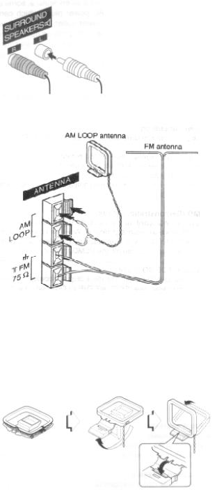
2 Connect the surround speakers to the main unit. (only for NSX-A54)
There are no differences between the surround speakers. Connect each surround speaker cord to the SURROUND SPEAKERS R or L terminal.
3 Connect the supplied antennas.
Connect the FM antenna to the FM 75 Ω terminals and the AM antenna to the AM LOOP terminals.
4 Connect the AC cord to an AC outlet.
To position the antennas
FM feeder antenna:
Extend this antenna horizontally in a T-shape and fix its ends to the wall.
AM loop antenna:
Position to find the best reception.
To stand the AM antenna on a surface
Fix the claw to the slot
NOTE
•Be sure to connect the speaker cords correctly. Improper connections can cause short circuits in the SPEAKERS terminals.
•Do not leave objects generating magnetism near the speakers as these object may be damaged.
•Do not bring the FM antenna near metal objects or curtain rails.
•Do not bring the AM antenna near other optional equipment, the stereo system itself, the AC cord or the speaker cords, since noise will be picked up.
•Do not unwind the AM antenna wire.
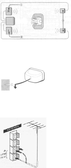
POSITIONING THE SPEAKERS (NSX-A54 only)
Position the speakers to make the most of the SURROUND effect.
Standard Positioning
? Front speaker (Right) @ Front speaker (Left) A Surround speakers
Place the surround speakers behind the listening area.
To mount the surround speakers on the wall
Mount each speaker on a spot that can hold its weight.
NOTE
Sound is not heard from the surround speakers when the SURROUND is set off.
CONNECTING AN OUTDOOR ANTENNA
For better FM reception, use of an outdoor antenna is recommended.
Connect the outdoor antenna to the FM 75 Ω terminals.
To connect other optional equipment → page 21.
PREPARATIONS (cont.) pg. 5
pg. 5
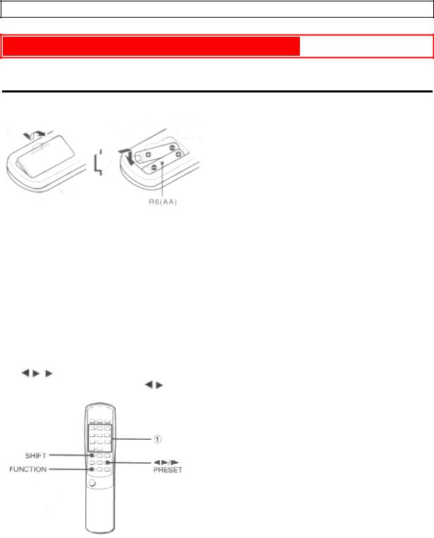
REMOTE CONTROL
Inserting batteries
Detach the battery cover on the rear of the remote control and insert two R6 (size AA) batteries.
When to replace the batteries
The maximum operational distance between the remote control and the sensor on the main unit should be approximately 5 meters(16 feet). When this distance decreases, replace the batteries with new ones.
To use the SHIFT button on the remote control
Buttons 1 have different functions. One of these functions is indicated on the button, and the other on the plate above the button.
To use the function on the button, simply press the button.
To use the function on the plate above the button, press the button while pressing the SHIFT button.
To use the FUNCTION button on the remote
The FUNCTION button substitutes for the function buttons (TAPE/DECK 1/2, TUNER, VIDEO/AUX, MD,CD) on the main unit. Each time the FUNCTION button is pressed, the next function is selected cyclically. When tapes are inserted in both decks, both decks are selected with the FUNCTION buttons.
The |
/ |
|
PRESET button on the remote control |
|
||
The function is the same as that of the |
|
DIRECTION/PRESET button on the main unit. |
||||
NOTE
•If the unit is not going to be used for an extended period of time, remove the batteries to prevent possible electrolyte leakage.
•The remote control may not operate correctly when:
-The line of sight between the remote control and the remote sensor inside the display window is exposed to intense light, such as direct sunlight.
-Other remote controls are used nearby (those of a television, etc.)
BEFORE OPERATION
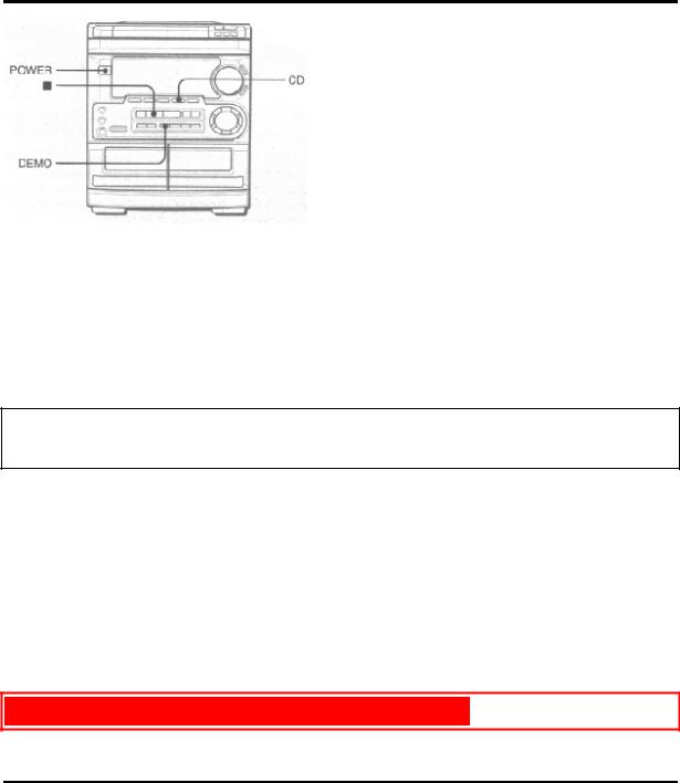
To turn the unit on
Press one of the function buttons (TAPE, TUNER, VIDEO/AUX,CD, MD).
Playback of the inserted disc or tape begins, or the previously tuned station is received (Direct Play Function). The POWER button is also available.
When the unit is turned on, the disc compartment may open and close to reset the unit.
DEMO (Demonstration) mode
When the AC cord is connected, the display window demonstrates the functions of the unit. When the power is turned on, the DEMO display is overridden by the operation display. When the power is turned off, the DEMO mode is restored.
To cancel DEMO mode
Press the DEMO button. The clock display appears. (To set the current time, see "SETTING THE CLOCK" on page 19.) To re-activate the DEMO mode, press the DEMO button again.
Illumination guides
Whenever the AC cord is connected or one of the function buttons is pressed, the buttons for that operation light up or flash. Example: When the AC cord is connected, the  SET button flashes as a guide to setting the current time.
Flash windows
The windows on the top of the unit and the cassette decks light up or flash while the unit is being powered on.
To turn off the light of the top window, press the  button while pressing the CD button. To turn back on, repeat the above.
To turn the unit off
Press the POWER button.
SOUND pg. 6
pg. 6
AUDIO ADJUSTMENTS
VOLUME
Turn the VOLUME control on the main unit, or press the VOLUME button on the remote control.
The volume level is displayed as a number from 0 to MAX (31).
The volume level is automatically set to 16 when the power is turned off with the volume level set to 17 or more.
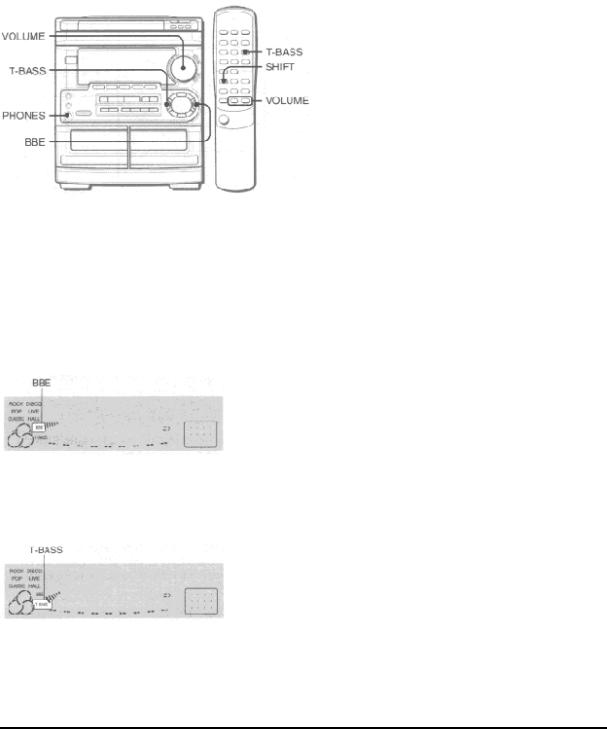
BBE SYSTEM
The BBE system enhances the clarity of high-frequency sound. It also enriches the KARAOKE function to make your voice sound clear and pleasant.
Press the BBE button.
Each time it is pressed, the level changes. Select one of the three levels, or the off position to suit your preference.
SUPER T-BASS SYSTEM
The T-BASS system enhances the realism of low-frequency sound.
Press the T-BASS button.
Each time it is pressed, the level changes. Select one of the three levels, or he off position to suit your preference.
NOTE
Low frequency sound may be distorted when the T-BASS system is used for a disc or tape in which low frequency sound is originally emphasized. In this case, cancel the T-BASS system.
GRAPHIC EQUALIZER
This unit provides the following three different equalization curves.
ROCK: Powerful sound emphasizing treble and bass
POP: More presence in the vocals and midrange
CLASSIC: Enriched sound with heavy bass and fine treble
Press the GEQ buttons.
To cancel the selected mode
Press the GEQ button repeatedly so that GEQ OFF appears on the display.
To select with the remote control
Press the GEQ button repeatedly while pressing the SHIFT button. The GEQ mode is displayed cyclically as follows.
Using the headphones
Connect headphones to the PHONES jack with a stereo standard plug (ø6.3 mm, 1/4 inch.) No sound is output from the speakers while the headphones are plugged in.
Sound adjustment during recording
The output volume and tone (except BBE) of the speakers or headphones may be freely varied without affecting the level of the recording.
NOTE
When playing back a tape recorded with BBE, it is recommended that BBE be set to off to avoid distorted high frequency sound.
|
|
|
|
|
RADIO RECEPTION |
pg. 7 |
|
|
|
|
|
MANUAL TUNING
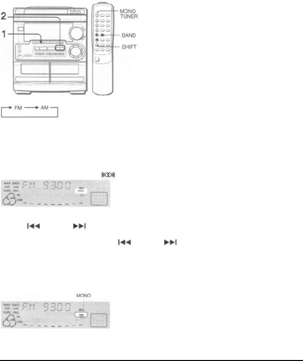
1 Press the TUNER/BAND button repeatedly to select the desired band.
When the TUNER/BAND button is pressed while the power is off, the power is turned on directly.
To select a band with the remote control
Press the BAND button while pressing the SHIFT button.
2 Press the  DOWN or
  UP button to select a station.
Each time the button is pressed, the frequency changes. When a station is received, "TUNE" is displayed for 2
seconds. During FM stereo reception, |
is displayed. |
To search for a station quickly (Auto Search)
Keep the |
DOWN or |
|
UP button pressed until the tuner starts searching for a station. After tuning in to a |
||||||
station, the search stops. |
|
|
|
|
|
|
|
|
|
To stop the Auto Search manually, press the |
DOWN or |
|
|
UP button. |
|
||||
• The Auto Search may not stop at stations with very weak signals. |
|
|
|
||||||
When an FM stereo broadcast contains noise
Press the MONO TUNER button while pressing the SHIFT button on the remote so that "MONO" appears on the display.
Noise is reduced, although reception in monaural.
To restore reception, press these buttons so that MONO disappears.
PRESETTING STATIONS
 Loading...