

Page 1
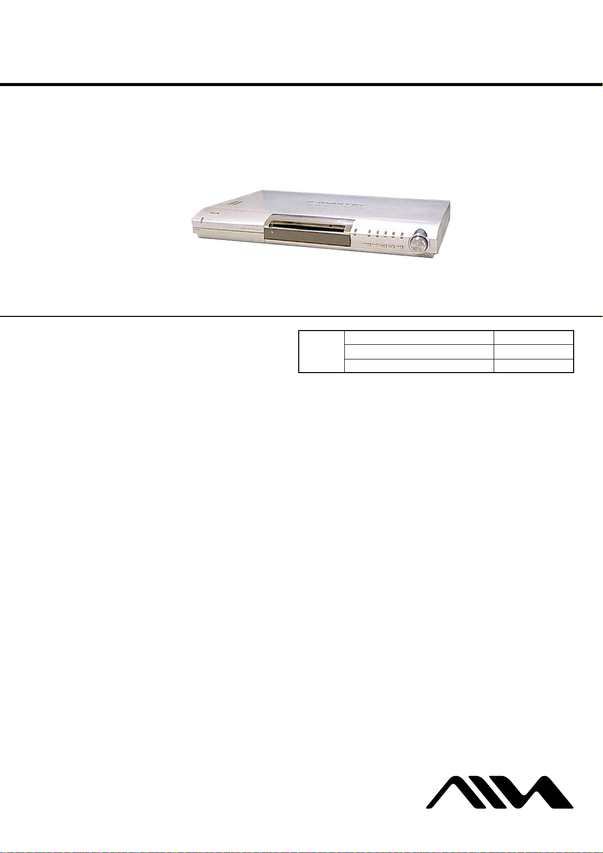
CX-VX5
SERVICE MANUAL
Ver. 1.2 2005. 04
• CX-VX5 is DVD receiver
in AVJ-X5.
DVD
Section
SPECIFICATIONS
AEP Model
UK Model
Model Name Using Similar Mechanism NEW
DVD Mechanism Type CDM80-DVBU24
Optical Pick-up Name DBU-1
Amplifier section
Stereo mode 60 W + 60 W (5 ohms at
1 kHz, THD 10 %)
Surround mode Front: 60 W + 60 W
Center*: 60 W
Surround*: 60 W + 60 W
(5 ohms at 1 kHz, THD
10 %)
Subwoofer*: 100 W
(3 ohms at 100 Hz, THD
10 %)
* Depending on the sound field settings and the source,
there may be no sound output.
Inputs VIDEO 1:
Sensitivity: 300 mV
Impedance: 50 kilohms
VIDEO 2:
Sensitivity: 300 mV
Impedance: 50 kilohms
MIC 1/MIC 2:
Sensitivity: 1 mV
Impedance: 10 kilohms
Outputs VIDEO 1 (AUDIO
OUT):
Voltage: 1 V
Impedance: 1 kilohm
Phones Accepts low-and high-
impedance headphones.
DVD system
Laser Semiconductor laser
(DVD: λ=650 nm)
(CD: λ=780 nm)
Emission duration:
continuous
Signal format system NTSC or NTSC/PAL
Frequency response (at 2 CH STEREO mode)
DVD (PCM): 2 Hz to 22
kHz (±1.0 dB)
CD: 2 Hz to 20 kHz (±1.0
dB)
Harmonic distortion Less than 0.03 %
– Continued on next page –
9-877-635-03
2005D04-1
© 2005. 04
DVD RECEIVER
Sony Corporation
Personal Audio Group
Published by Sony Engineering Corporation
1
Page 2
SECTION 4
TEST MODE
CX-VX5
[Version Display Mode]
*The software version is displayed.
Procedure:
1. Press three buttons of X , [PRESET +] and [FUNCTION]
simultaneously for two seconds.
2. The message “MODEL NAME & AREA” is displayed. The
version display mode is activated.
3. Press the [DISPLAY] button. “STR ***” is displayed.
4. Each time the [DISPLAY] button is pressed, the display changes
in the order of DVD, MODEL NAME & AREA and STR.
5. To exit from this mode, press the ?/1 button.
[Key T est Mode]
* Button check
Procedure:
1. Press three buttons of x , [FUNCTION] and Z simultaneously.
2. The message “KEY00 V.OL” is displayed.
3. Each time a button is pressed, “KEY00 V.OL” value increases.
However, once a button is pressed, it is no longer taken into
account.
4. When all buttons are pressed, “KEY12 V.OL” appears and the
number blinking is stopped.
5. To exit from this mode, disconnect the power cord.
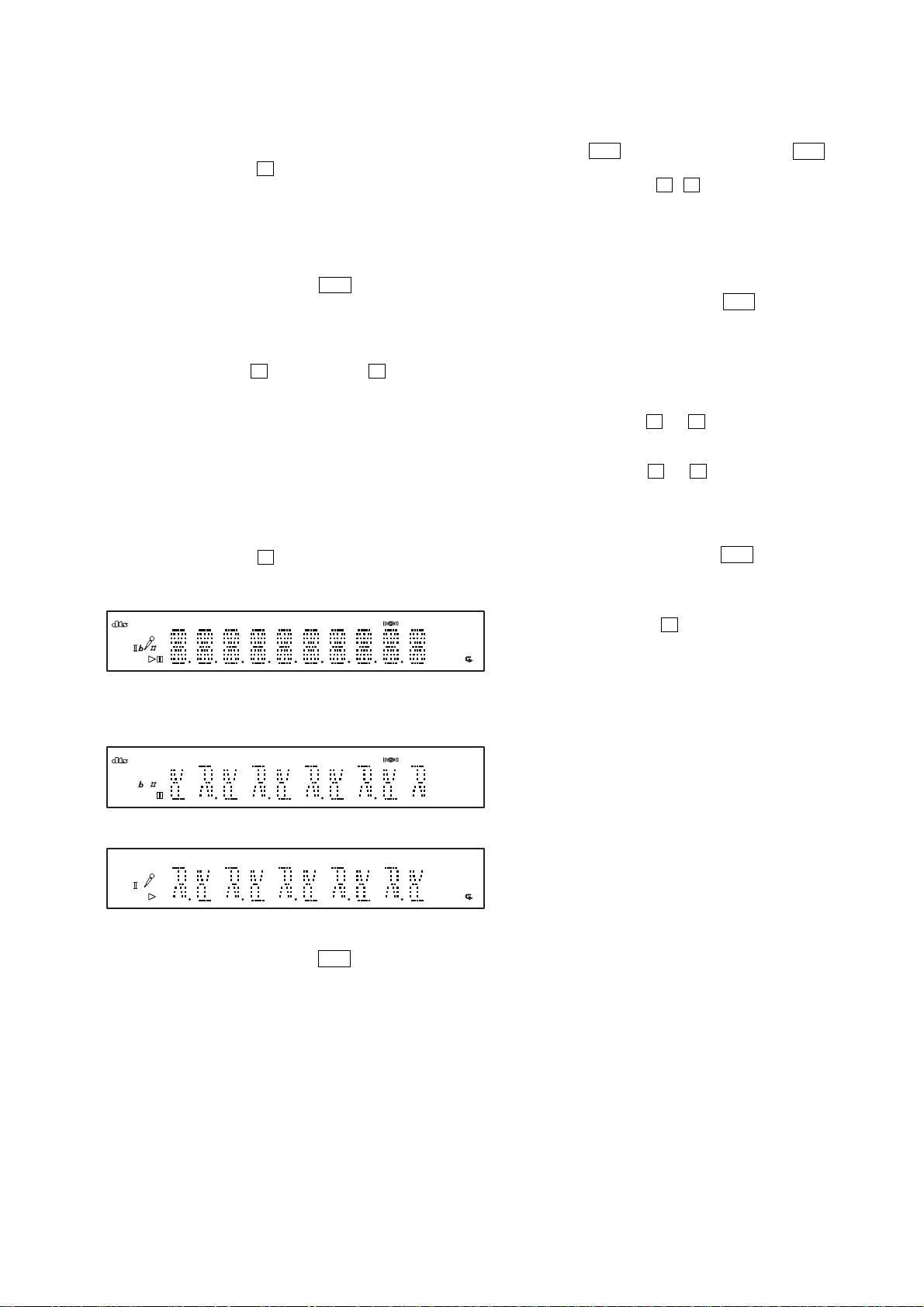
[Display T est Mode]
Procedure:
1. Press three buttons of X , [PRESET --] and [FUNCTION]
simultaneously.
2. All segments are turned on.
D
D
BASS
SLEEP
NTSC VF
D
D
D
PL
NIGHT
TRK CHAP ID3 ALBM MONO
TITLE
HMS
DVD SACD PBC
VCD MP3
kHz SHUF PGM
MHz
ALBM
TUNED
[OSD Test Mode]
Procedure:
1. Press the ?/1 button on the main unit or the ?/1 button on
the remote commander to turn the set on.
2. Press two buttons of Z , x and turn the [VOLUME] control
clockwise simultaneously.
3. The message “SERVICE IN” is displayed on the display. The
Test Mode Menu is displayed on the TV screen.
4. To execute each function, select the number on the remote
commander.
5. See the following section for explanation in detail.
6. To exit from this mode, press the ?/1 button.
[Disc Slot Lock]
The disc slot lock function for the antitheft of an demonstration
disc in the store is equipped.
Setting Procedure:
1. Turn the set on.
2. Press two buttons of x and Z simultaneously for five seconds.
3. The message “LOCKED” is displayed and the slot is locked.
Releasing Procedure:
1. Press two buttons of x and Z simultaneously for f ive seconds
again.
2. The message “UNLOCKED” is displayed and the slot is
unlocked.
Note : When “LOCKED” is displayed, the slot lock is not released
by turning power on/off with the ?/1 button.
[Repeat Limit Release Mode]
Procedure:
1. Press three buttons of x , [PRESET +] and [FUNCTION]
simultaneously.
1
2. Repeat limit is released.
3. Press the [DISPLAY] button, all segments are turned off.
4. When the [DISPLAY] button is pressed, the display will light
up as follows.
TITLE
NTSC
D
D
PL
NIGHT
CHAP ALBM MONO
DVD PBC
V MP3
SHUF
ALBM
5. Press the [DISPLAY] button and confirm the display.
D
BASS
VF
TRK ID3
SLEEP
D
D
HMS
SACD
CD
kHz PGM
MHz
TUNED
6. Every pressing of the [DISPLAY] button turns on each segments
in the same order.
7. To exit from this mode, press the ?/1 button.
1
27
Page 3
CX-VX5
[GENERAL DESCRIPTION]
The T est Mode allows you to make dia gnosis and adjustment easily
using the remote commander and monitor TV. The instructions,
diagnostic results, etc. are given on the on-screen display (OSD).
[TEST DISC LIST]
Use the following test disc on test mode.
TDV-520CSO (DVD-SL): PART No. J-2501-236-A
LUV-P01 (CD): PART No. 4-999-032-01
TDV-540C (DVD-DL): PART No. J-2501-235-A
Note: Do not use exiting test disc for DVD.
[ST ARTING TEST MODE]
1. Press the @/1 button to turn the power on.
2. Press two buttons of Z , x and turn the [VOLUME] control
clockwise simultaneously to enter the test mode.
3. It displays “SERVICE IN” on the fluorescent indicator tube,
and displays the Test Mode Menu on the monitor screen as
follows. (At the bottom of the menu screen, the model name
and revision number are displayed)
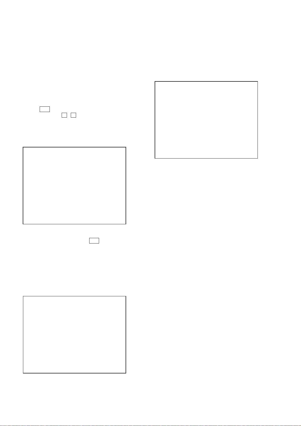
Test Mode Menu
0. Syscon Diagnosis
1. Drive Auto Adjustment
2. Drive Manual Operation
3. Mecha Aging
4. Emergency History
5. Mecha Error History
6. Version Information
7. Video Level Adjustment
Exit: POWER Key
Model :xx
Revision :x.xx
4. To execute each function, select the desired menu and press its
number on the remote commander.
5. To release from test mode, press the
power off.
@/1 button and turn the
0-1. All (All items continuous check)
This menu checks all diagnostic items continuously. Normally, all
items are checked successively one after another automatically
unless an error is found, but at a certain item that requires judgment
through a visual check to the result, the following screen is displayed
for the key entry.
• Example display
### Syscon Diagnosis ###
Diag All Check
No.2 Version
2-3. ROM Check Sum
Check Sum = ****
Press NEXT Key to Continue
Press PREV Key to Repeat
For the ROM Check, the check sum calculated by the Syscon is
output, and therefore you must compare it with the specified value
for confirmation.
Following the message, press the [NEXT ] button to go to the
next item, or press the [ PREV] button to repeat the same
operation again.
To quit the diagnosis and return to Check Menu screen, press the
.
>
[RETURN] key on the remote commander to display Check Menu.
• Error occurred
If an error occurred, the diagnosis is suspended and error is displayed.
Press the
diagnosis, or press the [ PREV] button to repeat the same check
where an error occurred, or press the [NEXT ] button to continue
the check from the item next to faulty item.
[RETURN] key on the remote commander to quit the
.
>
[OPERA TING TEST MODE]
0. SYSCON DIAGNOSIS
The same contents as board detail check by serial interface can be
checked from the remote commander operation.
On the Test Mode Menu screen, press [10/0] key on the remote
commander, and the following Check Menu will be displayed.
### Syscon Diagnosis ###
Check Menu
0. Quit
1. All
2. Version
3. EEPROM
4. GPIO
5. SD Bus
6. Video
0-0. Quit
Quit the Syscon Diagnosis and return to the Test Mode Menu.
General Description of Checking Method
Selecting 2 and subsequent items calls the submenu screen of each
item. And selecting 2 and subsequent items executes respective
menus and outputs the results.
For the contents of each submenu, see “Check Items List” as below .
Check Items List:
0-2. Version
0-2-1. All
0-2-2. Revision
0-2-3. ROM Check Sum
0-2-4. Model Type
0-2-5. Region
0-3. EEPROM Check
0-3-1. Sampling Check
0-3-2. Detail Check
0-4. GP I/O Check
0-5. SD Bus Check
0-6. Video Check
0-2. Version
0-2-2. Revision
The revision number of ROM (IC205) that the program for
the DVD system processor (IC206) is stored.
0-2-3. ROM Check Sum
Check sum is calculated. (4 digits hexadecimal number)
28
Page 4

CX-VX5
0-2-4. Model Type
Model name is displayed. (DAV-SCX)
0-2-5. Region
Model destination code is displayed. (2 digits number)
0-3. EEPROM Check
0-3-1. Sampling Check
EEPROM check at every 64 words.
It compares read data with write data of each address. When
there are discrepancies between two data, it displays error.
0-3-2. Detail Check
EEPROM check at every 1 word.
It compares read data with write data of each address. When
there are discrepancies between two data, it displays error.
0-4. GP I/O Check
Pull up/down setting check of the DVD system processor (IC206)
pin 150, 151 and 154 (for clock setting port).
0-5. SD Bus Check
SD bus data check between DVD decoder (IC701) and D-RAM
(IC706).
0-6. Video Check
Output the color bars for video level adjustment.
1. DRIVE AUTO ADJUSTMENT
On the Test Mode Menu screen, press the [1] key on the remote
commander, and the Adjustment Menu will be displayed.
## Drive Auto Adjustment ##
Adjustment Menu
0. ALL
1. DVD-SL
2. CD
3. DVD-DL
1-1. DVD-SL (single layer)
Press the 1 ke y on the remote commander and insert a DVD single
layer disc following the message. Then the adjustment will be made
through the steps below, then adjusted values will be written to the
EEPROM.
DVD Single Layer Disc Adjustment Steps:
1. Sled tilt reset
2. Disc check memory SL
3. Wait 300 msec
4. Set disc type SL
5. LD on
6. Spindle start
7. Wait 1 sec
8. Focus servo on 0
9. Auto track offset adjust
10. CLVA on
11. Wait 500 msec
12. Tracking on
13. Wait 1 sec
14. Sled on
15. Check CLV on
16. Auto LFO adjust
17. Auto focus offset adjust
18. Auto tilt position adjust
19. Auto focus gain adjust
20. Auto focus offset adjust
21. EQ boost adjust
22. Auto loop filter offset adjust
23. Auto track gain adjust
Search Check
24. 32 track jump forward
25. 32 track jump reverse
26. 500 track jump forward
27. 500 track jump reverse
28.All servo stop
29.EEP copy loop filter offset
1-2. CD
Press the
following the message. Then the adjustment will be made through
the steps below , then adjusted values will be written to the EEPR OM.
[2] key on the remote commander and insert a CD disc
Exit: RETURN
Normally,
DVD (dual layer) in this order . But, individual items can be adjusted
for the case where adjustment is suspended due to an error. In this
mode, the adjustment can be made easily through the operation
following the message displayed on the screen.
The disc used for adjustment must be the one specified for
adjustment.
1-0. ALL
Press the [10/0] key on the remote commander, and the servo set
data in EEPROM will be initialized. Then, 1. DVD-SL disc, 2. CD
disc and 3. DVD-DL disc are adjusted in this order.
Each time one disc was adjusted, it is ejected. Replace it with the
specified disc following the message. You can f inish the adjustment
by pressing the [RETURN] button on the remote commander.
Note: During adjustment of each disc, the measurement for disc type judg-
[10/0] is selected to adjust DVD (single layer), CD and
ment is made. As automatic adjustment does not judge the disc
type unlike conventional models, take care not to insert wrong type
discs. Also, do not give a shock during adjustment.
CD Adjustment Steps
1. Sled tilt rest
2. Disc check memory CD
3. Wait 500 msec
4. Set disc type CD
5. LD on
6. Spindle start
7. Wait 500 msec
8. Focus servo on 0
9. Auto track offset adjust
10. CLVA on
11. Wait 500 msec
12. Tracking on
13. (TC display start)
14. Wait 1 sec
15. Jitter display start
16. Sled ON
17. Check CLV on
18. Auto loop filter offset adjust
19. Auto focus offset adjust
20. Auto focus gain adjust
21. Auto focus offset adjust
22. EQ boost adjust
23. Auto LFO Adjust
29
Page 5
CX-VX5
24. Auto track gain adjust
Search Check
25. 32Tj forward
26. 32Tj reverse
27. 500Tj forward
28. 500Tj reverse
29. All servo stop
1-3. DVD-DL (dual layer)
Press the [3] key on the remote commander and insert a DVD dual
layer disc following the message. Then the adjustment will be made
through the steps below, then adjusted values will be written to the
EEPROM.
DVD Dual Layer Disc Adjustment Steps:
1. Sled tilt reset
2. Disc check memory DL
3. Wait 500 msec
4. Set disc type DL
5. LD on
6. Spindle start
7. Wait 1 sec
Layer 1 Adjust
8. Focus servo on 0
9. Auto track offset adjust
10. CLVA on
11. Wait 500 msec
12. Tracking on
13. Wait 500 msec
14. Sled on
15. Check CLV lock
16. Auto loop filter offset adjust, Auto focus adjust
17. Auto focus gain adjust
18. Auto focus offset adjust
19. EQ boost adjust
20. Auto loop filter offset adjust
21. Auto Track Gain Adjust
Search Check
22. 32 track jump forward
23. 32 track jump reverse
24. 500 track jump forward
25. 500 track jump reverse
Layer 0 Adjust
26. Focus jump (L1 t L0)
27. Auto track offset adjust L0
28. CLVA on
29. Wait 500 msec
30. Tracking on
31. Wait 500 msec
32. Sled on
33. Check CLV lock
34. Auto focus filter offset adjust
35. Auto Focus Adjust
36. Auto focus gain adjust
37. Auto focus offset adjust
38. EQ boost adjust
39. Auto Loop Filter Offset
40. Auto track gain adjust
Search Check
41. 32 track jump forward
42. 32 track jump reverse
43. 500 track jump forward
44. 500 track jump reverse
Layer Jump Check
45. Layer jump (L0 ? L1)
46. Layer jump (L1 ? L0)
47. All servo stop
2. DRIVE MANUAL OPERA TION
Note: This mode is used for design, and not used in service fundamen-
tally.
On the Test Mode Menu screen, press the [2] key on the remote
commander, and the Operation Menu will be displayed. For the
manual operation, each servo on/off control and adjustment can be
executed manually.
## Drive Manual Operation ##
Operation Menu
1. Disc Type
2. Servo Control
3. Track/Layer Jump
4. Non EEPROM Write Adjust
5. EEPROM Write Adjust
6. Memory Check
7. Disc Check Memory
8. Error Rate Display
9. SACD Water Mark
Exit: RETURN
In using the manual operation menu, take care of the following
points. These commands do not provide protection, thus requiring
correct operation. The sector address or time code field is displayed
when a disc is loaded.
Note:
1. Set correctly the disc type to be used on the Disc Type screen.
2. In case of an alarm, immediately press the x button to stop the
servo operation, and press the @/1 button to turn the power off.
Basic operation:
(controllable from front panel or remote commander)
@/1 :Power OFF (release the Test Mode)
x : Servo stop
A : Stop and eject
[RETURN] : Return to Operation Menu or Test
Mode Menu
[ PREV], [NEXT ] :Transition between sub modes of menu
>.
[1] to [9], [10/0] : Selection of menu items
Cursor o/
O
: Increase/Decrease in manually
adjusted value
30
Page 6

CX-VX5
2-1. Disc Type
Disc Type
Disc Type Select
1. Disc Type Auto Check
2. Set Disc Type DVD
3. Set Disc Type CD
4. Set Disc Type Hybrid
Exit: RETURN
2-1-1. Disc Type Auto Check
1) Press the [1] key on the remote commander to display the Disc
Type Auto Check screen.
2) Insert a disc and press the [ENTER] key on the remote
commander.
3) It judges the type of inserted disc automatically and displays
the disc type and so on as below.
Disc Type Auto Check
Disc Type xx
Layer xx
Mirr Time xx
Mirr Count xx
FZC Count xx
PI Reference xx
PI Peak xx
2-1-3. Disc T ype CD
It sets up so that it may judge as a disc type of specification of the
disc with which the set was inserted.
[1]: CD disc (normal speed, 12 cm)
[2]: CD disc (double speed, 12 cm)
[3]: CD disc (normal speed, 8 cm)
[4]: CD disc (double speed, 8 cm)
[5]: CD-RW disc (normal speed, 12 cm)
[6]: CD-RW disc (double speed, 12 cm)
[7]: CD-RW disc (normal speed, 8 cm)
[8]: CD-RW disc (double speed, 8 cm)
2-1-4. Disc Type Hybrid
It sets up so that it may judge as a disc type of specification of the
disc with which the set was inserted.
[1]: SACD Hybrid disc (SACD layer, 12 cm)
[2]: SACD Hybrid disc (CD layer, normal speed, 12 cm)
[3]: SACD Hybrid disc (CD layer, double speed, 12 cm)
[4]: SACD Hybrid disc (SACD layer, 8 cm)
[5]: SACD Hybrid disc (CD layer, normal speed, 8 cm)
[6]: SACD Hybrid disc (CD layer, double speed, 8 cm)
2-2. Servo Control
Note: Be sure to perform the disc type setup before performing this item.
Servo Control
1.LD off R.Sled FWD
2.Focus off L.Sled REV
3.SPDL off U.Sled Reset
4.CLVA off D.Sled Limit
5.Trk. off
6.Sled off
7.Fcs.Srch off
ENTER.Execute
Exit: RETURN
Disc Type : CD, DVD or Hybrid (SACD)
Layer : SINGLE, DUAL or HYBRID
Mirr Time : Mirror time of between disc surface and record
surface when disc type judgment. (hexadecimal
number)
Mirr Count : The number of times which mirror counts between
disc surface and record surface when disc type
judging. (hexadecimal number)
FZC Count : The number of times which focus zero cross points
of each layer when lens down. (hexadecimal number)
PI Reference : The average of PI reference voltage. (hexadecimal
number)
PI Peak : PI peak level voltage. It performs only when disc
type judgment is successful. (hexadecimal number)
2-1-2. Disc Type DVD
It sets up so that it may judge as a disc type of specification of the
disc with which the set was inserted.
[1]: DVD single layer disc (12 cm)
[2]: DVD dual layer disc (0 layer, 12 cm)
[3]: DVD dual layer disc (1 layer, 12 cm)
[4]: DVD-RW disc (12 cm)
[5]: DVD single layer disc (8 cm)
[6]: DVD dual layer disc (0 layer, 8 cm)
[7]: DVD dual layer disc (1 layer, 8 cm)
[8]: DVD-RW disc (8 cm)
0.All Servo Off
Exit: RETURN
On this screen, the servo on/off control necessary for replay is
executed. Normally, turn on each servo from 1 sequentially and
when CLVA is turned on, the usual trace mode becomes active. In
the trace mode, DVD sector address or CD time code is displayed.
This is not displayed where the spindle is not locked.
The spindle could run overriding the control if the spindle system is
faulty or RF is not present. In such a case, do not operate CLVA.
[1] LD :Turn on/off the laser.
[2] Focus : Search the focus and turn on the focus.
[3] SPDL :Turn on/off the spindle.
[4] CLVA :Turn on/off normal servo of spindle servo.
[5] Trk. : Turn on/off the tracking servo.
[6] Sled : Turn on/off the sled servo.
[7] FCS. Srch : Turn on/off the focus search.
[8] FCS. OppL : Turn on/of f the focus search to another layer
of designated layer in Disc T ype setting. (dual
layer disc only)
[10/0] :All servo off.
[R] Sled FWD (right cursor) :Move the sled forward.
[L] Sled REV (left cursor) : Move the sled reverse.
[U] Sled FWD (up cursor) : Reset the sled.
[D] Sled REV (down cursor): Limit in the sled.
31
Page 7
CX-VX5
2-3. Track/Layer Jump
Track/Layer Jump
1. 1Tj FWD R.Lj L0>L1
2. 1Tj REV L.Lj L1>L0
3.500Tj Fine FWD U.Fj L0>L1
4.500Tj Fine REV D.Fj L1>L0
5.10kTj Dirc FWD
6.10kTj Dirc REV
7.20kTj Dirc FWD
8.20kTj Dirc REV
0. All Servo Off
Exit: RETURN
On this screen, track jump, etc. can be performed. Only for the DVD
dual layer disc, the focus jump and layer jump are displayed in the
right field
[1] 1Tj FWD : 1 track jump forward.
[2] 1Tj REV : 1 track jump reverse.
[3] 500Tj FWD: 500 track jump (fine search)forward.
[4] 500Tj REV : 500 track jump (fine search) reverse.
[5] 10kTj FWD: 10k track jump (direct search) forward.
[6] 10kTj REV : 10k track jump (direct search) reverse.
[7] 20kTj FWD: 20k track jump (direct search) forward.
[8] 20kTj REV : 20k track jump (direct search) reverse.
[10/0] : All servo off.
2-4. Non EEPROM Write Adjust
Non EEPROM Write Adjust
1. Focus Offset
2. Focus Gain
3. Trk. Offset Coarse
4. Trk. Offset Fine
5. Trk. Gain
6. EQ Boost
0.All Servo Off
Exit: RETURN
2-5. EEPROM Write Adjust
EEPROM Write Adjust
1. Focus Offset
2. Focus Gain
3. Trk. Offset Coarse
4. ——————
5. Trk. Gain
6. EQ Boost
0.All Servo Off
Exit: RETURN
On this screen, each item can be adjusted automatically. Select the
desired number
selected item is adjusted automatically.
[1] to [10/0] from the remote commander, and
[1] Focus Offset: Adjusts focus offset.
[2] Focus Gain : Adjusts focus gain.
[3] TRK. Offset : Adjusts tracking offset of the RF amp
(IC001) side.
[5] TRK. Gain : Adjusts track gain.
[6] EQ Boost : Adjusts amount of boost of equalizer.
[10/0] : All servo off.
2-6. Memory Check
Display images are shown as follows, and all two screens are able
to switch by theOkey (UP) or okey (DW).
EEPROM Data 1/2 CD SL L0 L1
Focus Gain xx xx xx xx
Trk. Gain xx xx xx xx
Focus Offset xx xx xx xx
Trk. Offset xx xx xx xx
EQ. Boost xx xx xx xx
PI Level xx xx -- -Fcs. Balance -- xx -- -Jitter xx xx xx xx
Mirror Time xx xx xx -FE Level -- xx -- -Traverse Lv1. -- xx -- -Next:DW Default:CLR Exit:RET
On this screen, each item can be adjusted manually. Select the desired
number
setting for the selected item will be displayed, then increase or
decrease numeric value with theOkey or okey. This value is
stored in the EEPROM. If CLV has been applied, the jitter is
displayed for reference for the adjustment.
[1] to [10/0] from the remote commander, and current
[1] Focus Offset: Adjusts focus offset.
[2] Focus Gain : Adjusts focus gain.
[3] TRK. Offset : Adjusts tracking offset of the RF amp
(IC001) side.
[4] TRK. Offset : Adjusts tracking offset of the DSP (IC401)
side.
[5] TRK. Gain : Adjusts track gain.
[6] EQ Boost : Adjusts amount of boost of equalizer.
[10/0] : All servo off.
32
EEPROM Data 2/2 CDRW DVDRW
Focus Gain xx xx
Trk. Gain xx xx
Focus Offset xx xx
Trk. Offset xx xx
EQ. Boost xx xx
Prev:UP Default:CLR Exit:RET
On this screen, current servo adjusted data stored in the EEPROM
are displayed. The adjusted data are initialized by pressing the
[CLEAR] key, but be careful that they are not recoverable after
initialization.
Before clearing the adjusted data, make a note of the set data. This
screen will also appear if [0]-All is selected in the Drive Auto
Adjustment. In this case, default setting cannot be made.
Page 8
CX-VX5
2-7. Disc Check Memory
Disc Check Memory
1. SL Disc check
2. CD Disc check
3. DL Disc check
Exit: RETURN
On this screen, measure the mirror time of chucked disc, and write
to the EEPROM.
2-8. Error Rate Display
Error Rate Display
UC CR Address
PI1 Err Now xx xxxx xxxxxxxx
Max xx xxxx xxxxxxxx
Avg xx xxxx
PI2 Err Now xx xxxx xxxxxxxx
Max xx xxxx xxxxxxxx
Avg xx xxxx
PO Err Now xx xxxx xxxxxxxx
Max xx xxxx xxxxxxxx
Avg xx xxxx
Start:ENTER Exit: RETURN
On this screen, measure and display the error rate.
UC : Incorrect value
CR : Correct value
2-9. SACD Water Mark Check
SACD Water Mark Check
PSP AMP
PSN
Start: ENTER Exit: RETURN
On this screen, measure the PSP AMP v alue and PSN value of SACD
water mark.
3. EMERGENCY HISTORY
On the Test Mode Menu screen, selecting [4] displays the
information such as servo emergency history.
The history information from last 1 up to 10 can be scrolled with
theOkey orokey. Also, specific information can be displayed
by directly entering that number with ten keys.
### EMG. History ###
Laser Hours CD xxxxhxxm
DVD xxxxhxxm
a. bb xx xx xx xx xx xx xx
xx xx xx xx xx xx xx xx
a. bb xx xx xx xx xx xx xx
xx xx xx xx xx xx xx xx
Select:1-9 Scroll:UP/DOWN
(1.Latest EMG.) Exit: RETURN
xxxxhxxm: The laser on total hours. Data below minutes are
omitted.
a. : Error number.
bb : Error code.
xx : Not used.
• Clearing History Information
Clearing laser hours:
Press the [DVD DISPLAY] and [CLEAR] keys in this order.
Then both CD and DVD data are cleared.
Clearing emergency history:
Press the
Initializing set up data:
Press [DVD MENU] and [CLEAR] keys in this order.
The data have been initialized when “EEPROM Initialize
Finished.”. message is displayed. The EMG. History screen
will be restored soon.
• Code list of Emergency History
10: Communication to RF AMP (IC001) failed.
11: Each servo for focus, tracking, and spindle is unlocked.
12: Check sum error of EEPROM (IC203).
14: Communication to servo DSP (IC401) failed, or servo DSP
15: Communication to DVD decoder (IC701) failed, or DVD
16: Communication to DSD decoder (IC801) failed, or DSD
20: Initialization of sled servo failed. It is not placed in the ini-
23: Sled servo operation error.
24: Made a request to move the sled servo to wrong position.
30: Tracking balance adjustment error.
31: Tracking gain adjustment error.
33: Focus bias adjustment error.
34: Focus gain adjustment error.
35: Equalizer adjustment error.
40: Focus servo does not operate.
41: With a DVD dual layer disc, focus jump failed.
50: CLV (spindle) servo does not operate.
51: Spindle does not stop.
60: Made a request to seek nonexistent address.
61: Seek error of retry more than regulated times.
70: Control data could not be read.
80: Disc reading failed.
[DVD TOP MENU] and [CLEAR] keys in this order.
(IC401) is faulty.
decoder (IC701) is faulty.
decoder (IC801) is faulty.
tial position.
33
Page 9
CX-VX5
4. MECHA ERROR HISTORY
On the T est Mode Menu screen, selecting [5] displays the information
of mechanism deck error history.
The history information from last 1 up to 8 can be scrolled with the
key orokey. Also, specific information can be displayed by
O
directly entering that number with ten keys.
### Mecha Error History ###
1. aa bb cc dd xx xx xx xx
2. aa bb cc dd xx xx xx xx
3. aa bb cc dd xx xx xx xx
4. aa bb cc dd xx xx xx xx
5. aa bb cc dd xx xx xx xx
6. aa bb cc dd xx xx xx xx
7. aa bb cc dd xx xx xx xx
8. aa bb cc dd xx xx xx xx
Scroll:UP/DOWN
(1.Latest Err.) Exit: RETURN
aa : The error in the midst of initializing the mechanism deck.
bb : The error in the midst of loading operation.
cc : The error in the midst of up/down the stocker.
dd : The error in the midst of switching the mechanism deck mode.
xx : Not used.
• Error code (bb)
00 : Initializing the mechanism deck.
10 : Retry over of eject and loading.
30 : Open operation in no disc status.
60 : Retry over of eject and loading.
70 : Disc is chucking position.
81 : Retry failed of disc movement from chucking position to
stocker.
83 : Retry preparation failed of disc movement from chucking
position to stocker.
90 : Disc is stored in the stocker.
A1 : Retry failed of disc movement from stocker to chucking
position.
A3 : Retry preparation failed of disc movement from stocker to
chucking position.
B0 : Just before the release operation.
B1 : Retry failed of the release operation.
• Error code (cc)
10 : Under a stop.
22 : Retry preparation failed.
23 : Retry failed.
• Error code (dd)
10 : Under a stop.
22 : Retry preparation failed.
23 : Retry failed.
• Error code (aa)
FF : Complete the initializing. (normal operation)
11 : Stocker movement (to chucking position) failing in the midst
of initializing the mechanism deck.
12 : Stocker movement (to chucking position) failing in the midst
of initializing the mechanism deck.
1x : Initializing the mechanism deck.
2x : Initializing the mechanism deck.
3x : Initializing the mechanism deck.
41 : Disc eject failing in the midst of initializing the mechanism
deck.
4x : Initializing the mechanism deck.
50 : Disc eject failing in the midst of initializing the mechanism
deck.
5x : Initializing the mechanism deck.
A2 : Disc eject failing in the midst of initializing the mechanism
deck.
Ax : Initializing the mechanism deck.
D3 : Disc eject failing in the midst of initializing the mechanism
deck.
Dx : Initializing the mechanism deck.
Ex : Initializing the mechanism deck.
5. VERSION INFORMATION
On the Test Mode Menu screen, selecting [6] displays the ROM
version and region code.
The parenthesized hexadecimal number in version field is checksum
value of ROM.
## Version Information ##
IF con. Ver.x. xx
SYScon. Ver.x. xx (xxxx)
Model
Region 0x
Config xxxxxxxx
Front End Ver.x.xx
Exit: RETURN
IF con. : The version of system controller (IC901).
SYScon. : The version of DVD system processor (IC206).
Front End: The version of mechanism controller (IC301).
6. VIDEO LEVEL ADJUSTMENT
On the Test Mode Menu screen, selecting [7] displays color bars
for video level adjustment. During display of color bars, OSD
disappears but the menu screen will be restored if pressing the
[RETURN] key.
34
Page 10
SECTION 5
e
p
ELECTRICAL ADJUSTMENT
[TEST DISC LIST]
Use the following test disc on test mode.
TDV-520CSO (DVD-SL): PART No. J-2501-236-A
LUV-P01 (CD): PART No. 4-999-032-01
TDV-540C (DVD-DL): PART No. J-2501-235-A
Note: Do not use exiting test disc for DVD.
AUTO SERVO ADJUSTMENT
After parts related to the servo circuit (RF amplifier (IC001), DSP
(IC401), motor driver (IC501), EEPROM (IC302) so on) are
replaced, re-adjusting the servo circuit is necessary. Select “ALL”
at “1. DRIVE AUTO ADJUSTMENT” (Refer to page 29 in TEST
MODE) and adjust DVD-SL (single layer), CD and D VD-DL (dual
layer).
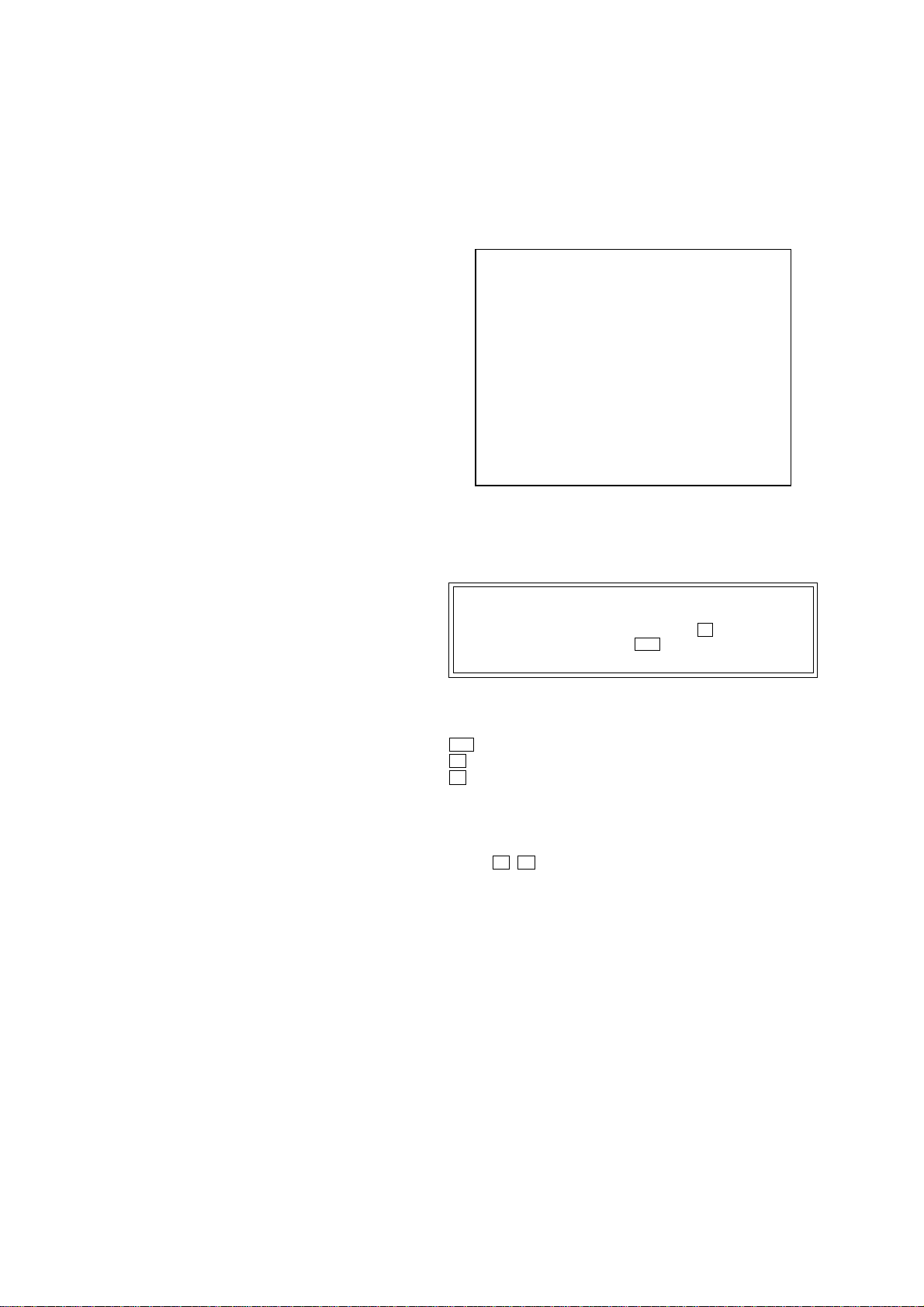
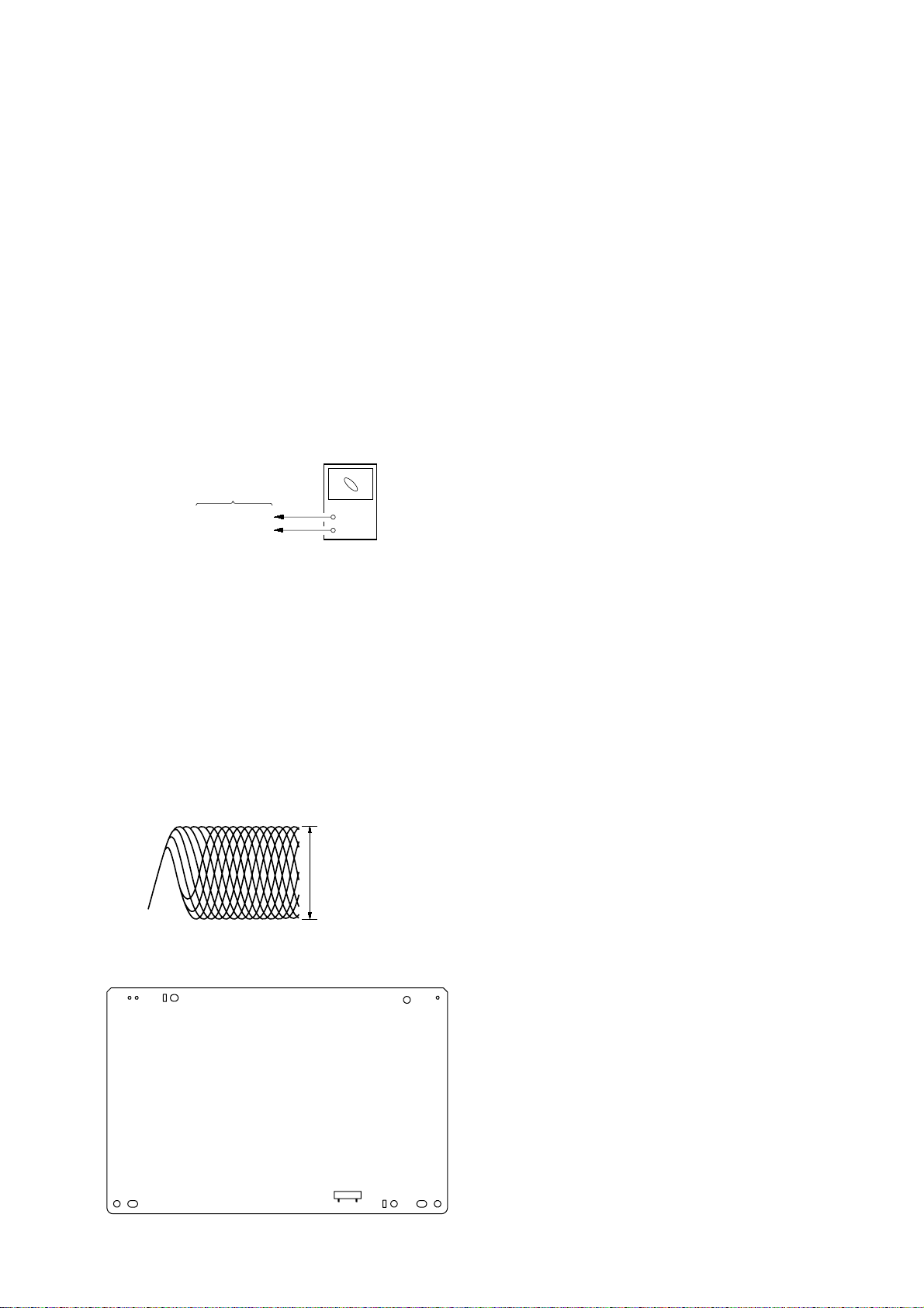
DECISION TO PASS OR FAIL OF THE OPTICAL
PICK-UP BLOCK
Connection:
oscilloscop
CX-VX5
Ver 1.1
DMB03 board
CN901 pin 1
CN901 pin 3
Procedure:
1. Connect an oscilloscope to test point pin 1 and pin 3 of CN901
on the DMB03 board.
2. Turn the power on.
3. Put the disc (LUV-P01) (Part No.: 4-999-032-01) (CD) in to
playback.
4. Confirm that oscilloscope waveform is clear and check RF
signal level is correct or not.
5. Put the disc (TDV -520CSO) (Part No.: J-2501-236-A) (D VD) in
to playback.
6. Perform Comfirmation in the same manner as step 4.
Note: A clear RF signal waveform means that the shape “◊” can be clearly
distinguished at the center of the waveform.
RF signal waveform
+
–
VOLT/DIV : 200 mV
TIME/DIV : 500 nS
CD : 1.05 ± 0.2 Vp-p
DVD : 1.09
±
0.2 Vp-
Checking Location:
– DMB03 BOARD (SIDE A) –
CN901
1
7
35
Page 11
CX-VX5
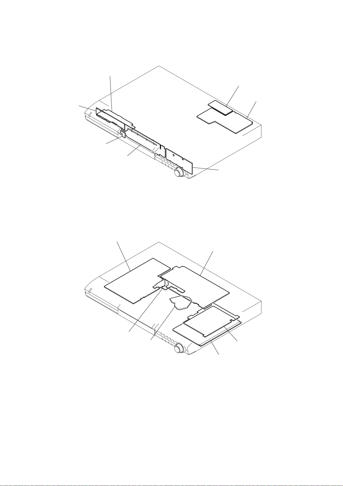
6-1. CIRCUIT BOARDS LOCATION
F-AV board
P-KEY board
RM board
SECTION 6
DIAGRAMS
SCART board
I/O board
FL board
KEY board
POWER board
DRIVER board
RF board
AMP board
MICON board
DMB03 board
36
Page 12
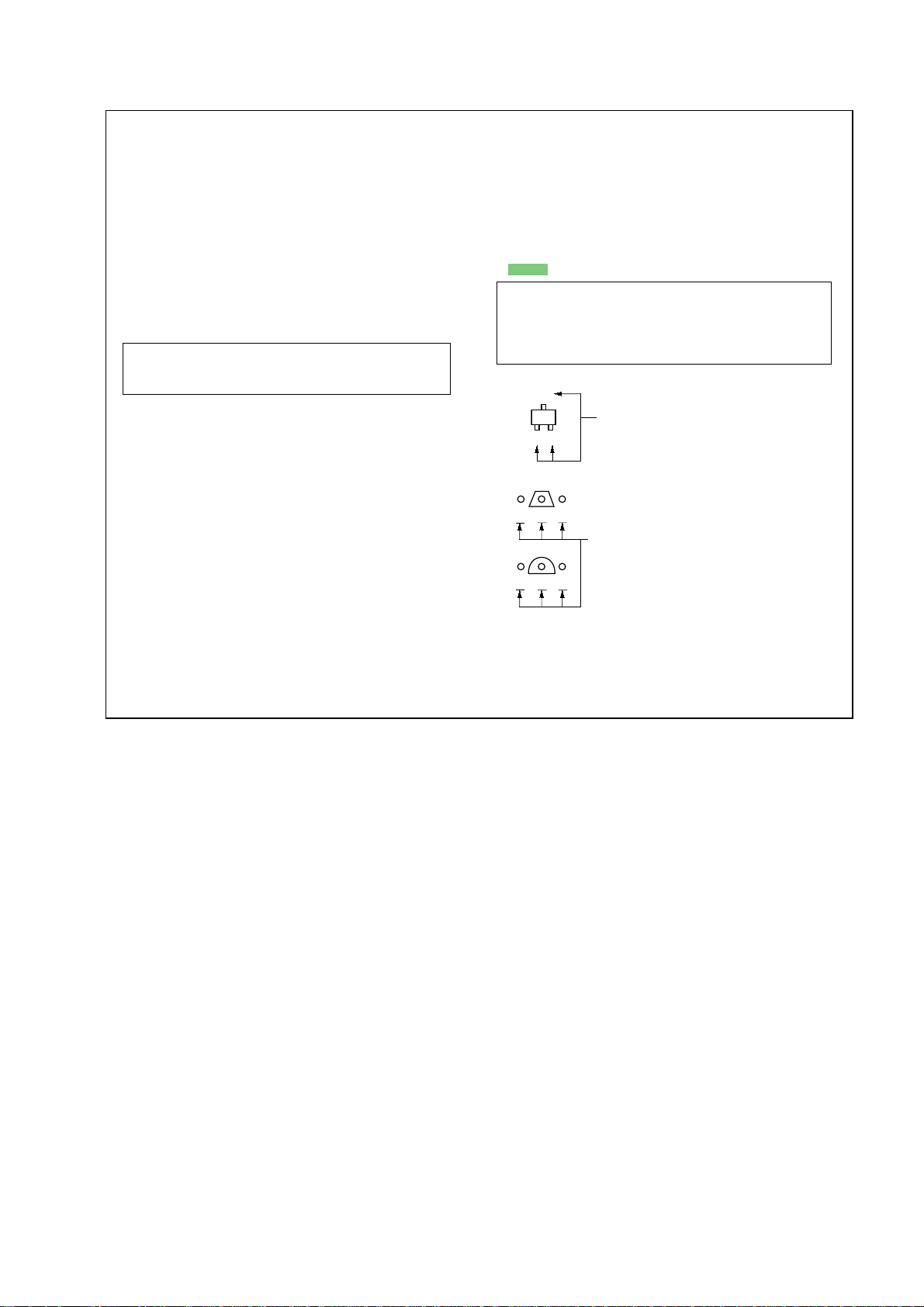
THIS NOTE IS COMMON FOR PRINTED WIRING
C
B
These are omitted.
E
Q
BOARDS AND SCHEMATIC DIAGRAMS.
(In addition to this, the necessary note is
printed in each block.)
CX-VX5
for schematic diagram:
• All capacitors are in µF unless otherwise noted. pF: µµF
50 WV or less are not indicated except for electrolytics
and tantalums.
• All resistors are in Ω and 1/
specified.
f
•
: internal component.
4
W or less unless otherwise
• 2 : nonflammable resistor.
• 5 : fusible resistor.
• C : panel designation.
Note: The components identified by mark 0 or dotted line
with mark 0 are critical for safety.
Replace only with part number specified.
• A : B+ Line.
• B : B– Line.
•Voltage and waveforms are dc with respect to ground
under no-signal (detuned) conditions.
no mark : DVD PLAY
(): DVD STOP
•Voltages are taken with a VOM (Input impedance 10 MΩ).
Voltage variations may be noted due to normal production tolerances.
•Waveforms are taken with a oscilloscope.
Voltage variations may be noted due to normal production tolerances.
• Circled numbers refer to waveforms.
• Signal path.
F : TUNER (FM/AM)
L : VIDEO (COMPONENT)
r : VIDEO (COMPOSITE)
d : VIDEO (AUDIO)
J : DVD (AUDIO)
c : DVD (RF)
I : DVD (DIGITAL)
for printed wiring boards:
• X : parts extracted from the component side.
• x : parts mounted on the conductor side.
a
•
•
: Through hole.
f
: internal component.
• : Pattern from the side which enables seeing.
Caution:
Pattern face side: Parts on the pattern face side seen from the
(Side B) pattern face are indicated.
Parts face side: Parts on the parts face side seen from the
(Side A) parts face are indicated.
Q
BCE
Q
B
C
These are omitted.
E
37
Page 13
CX-VX5
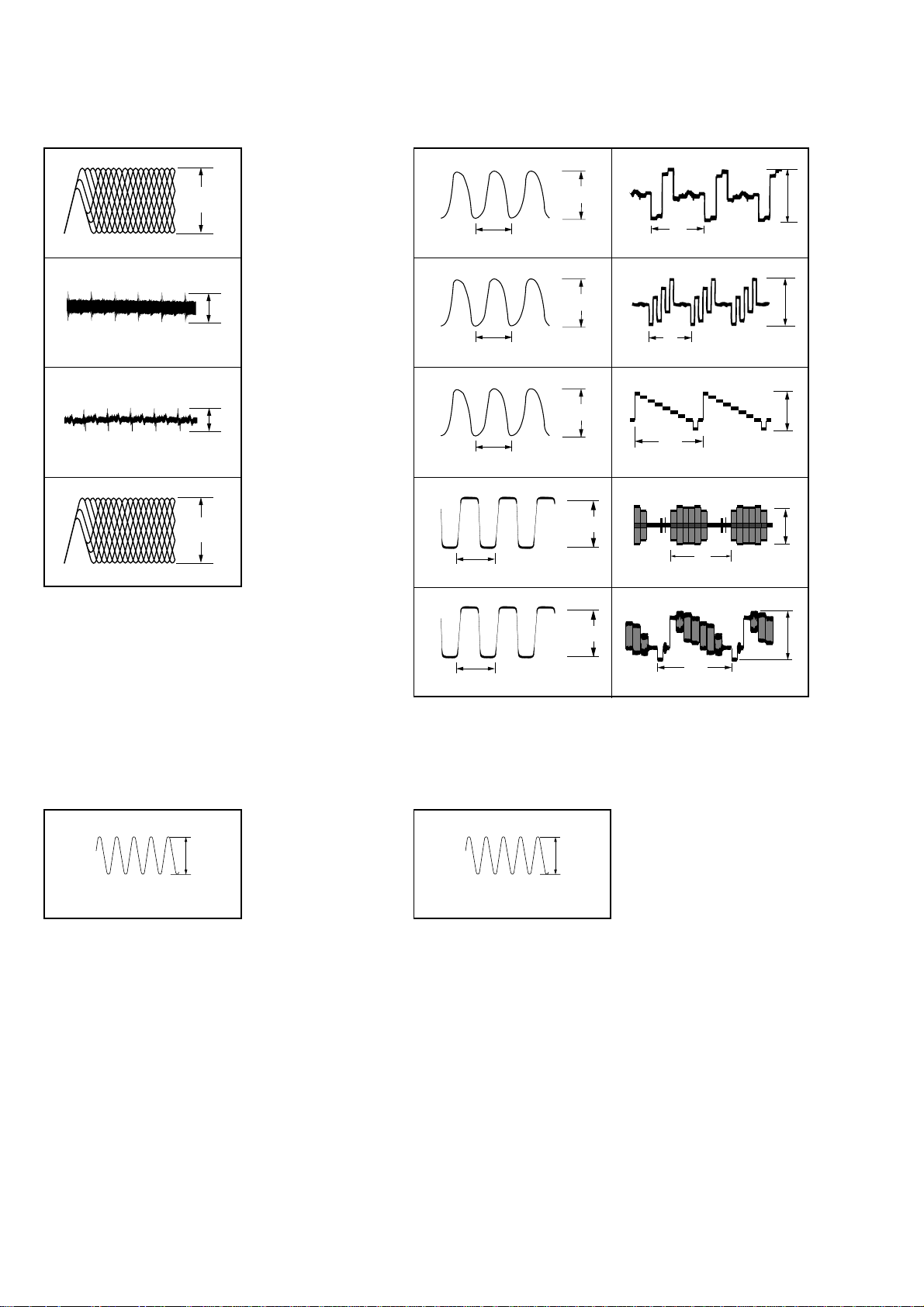
•Waveforms
– RF Board –
200mV/DIV, 100ns/DIV
1
– DM03 Board –
16
1V/DIV, 20ns/DIV
200mV/DIV, 20µs/DIV
IC001
500mV/DIV, 1ms/DIV
2
IC001
100mV/DIV, 1ms/DIV
3
IC001
500mV/DIV, 100ns/DIV
4
IC001
(DVDRFP)
1
(TE)
el
(FE)
r;
(RFAC)
tj
800mVp-p
0.5Vp-p
0.3Vp-p
1.3Vp-p
3.9Vp-p
50ns
IC901
27
38
49
5q;
1V/DIV, 10ns/DIV
IC906
1V/DIV, 10ns/DIV
IC906
1V/DIV, 10ns/DIV
IC906
1V/DIV, 10ns/DIV
(XTAL)
r;
37ns
3
37ns
8
29.5ns
q;
5.6Vp-p
(MO1)
4.5Vp-p
(XTO)
4.5Vp-p
(SO2)
4.6Vp-p
H
H
H
(VDAC 4)
<zz.>
(VDAC 3)
<zxx>
(VDAC 2)
<zxb>
H
(VDAC 1)
<zx,>
IC207
200mV/DIV, 20µs/DIV
IC207
200mV/DIV, 20µs/DIV
IC207
200mV/DIV, 20µs/DIV
IC207
500mV/DIV, 20µs/DIV
820mVp-p
820mVp-p
1.2Vp-p
900mVp-p
– I/O Board –
1V/DIV, 50ns/DIV
1
4.332MHz
IC108
qf
(XO)
2.5Vp-p
29.5ns
qd
(SO3)
IC906
– MICON Board –
1V/DIV, 50ns/DIV
1
5MHz
IC501
qf
(XI)
2.2Vp-p
IC207
H
(VDAC 0)
<zcz>
1.3Vp-p
38
Page 14
6-2. PRINTED WIRING BOARD — DVD MECHANISM SECTION (1/2) — • Refer to page 36 for Circuit Boards Location and page 37 for Common Note on Printed Wiring Boards.
: Uses unleaded solder.
CX-VX5
A
B
C
D
E
1
A
DMB03
BOARD
CN501
(Page 42)
234567891011121314
D002
D001
L002
L001
C026
IC001
(SIDE B)
C003
C030
C029
R026
48
33
C031
R033
C006
C032
C034
C036
C001
R034
R027
R028
R029
R032
C005
C033
C035
R006
R010
C012
CN002
C011
C010
R008
C049
R009
R007
R005
R003
R004
RF BOARD
Q002
Q001
C013
C037
(SIDE A)
CN001
C008
C009
C028 C027
C038
C039
C040
C022
C041
C020
C017
C015
R014
R012
R018
R016
C023
R021
C021
FLEXIBLE
BOARD
1-685-250-
R001
OPTICAL PICK-UP
11
CN003
BLOCK
(DBU-1)
C004
C002
C016
C042
RF BOARD
R025
R022
R023
C024
C019
C018
1
C014
R013
R011
16
R017
R015
R041
C025
R024
64 49
17 32
F
• Semiconductor
Location
Ref. No. Location
D001 C-11
D002 B-11
IC001 D-11
Q001 C-3
Q002 B-3
1-684-822-
11
(11)
R019
R020
R035
1-684-822-
11
(11)
39 39
Page 15
CX-VX5
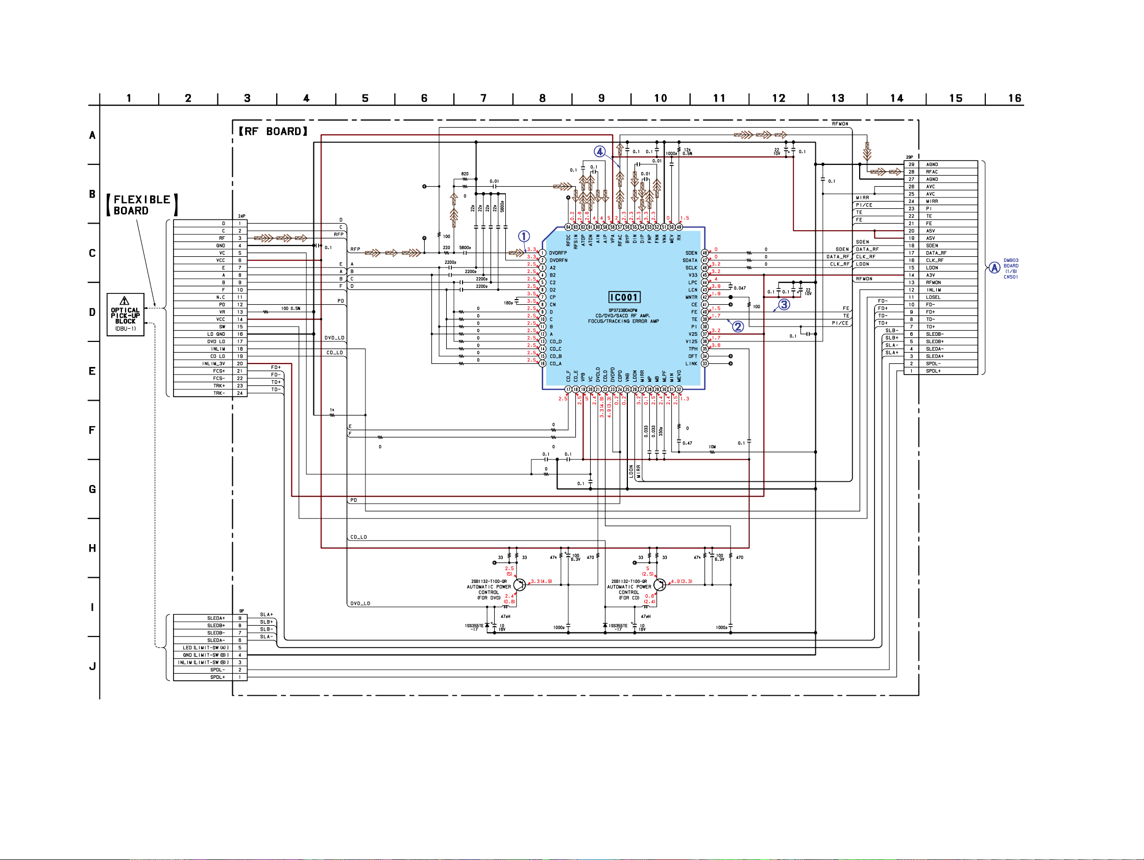
6-3. SCHEMATIC DIAGRAM — DVD MECHANISM SECTION (1/2) — • Refer to page 37 for Common Note on Schematic Diagrams and page 38 for Waveforms.
CN001
R001
C009
R041
R023
JL005
JL007
R025
R022
C017
C016
R019 R020
R024
C019
C015
C014
R014
R013
R012
R011
R018
R017
R016
R015
C020
C021
C022
C024
C023
C018
C042
R035
C008
R021
JL004
C041
C025
C040
C026
IC001
C030
C029
R032
R027
R028
R029
C006
C033 C012
C049
C013
C005
CN002
C035
(Page 44)
C038
C037
C031
R026
R033
C036
R034
C032
JL006
JL003
JL002
JL001
C034
C027C028
C039
CN003
C001
R005 R009
IOP2
Q001 Q002
R004R003
L001
C002D001
C010
R006
4040
IOP1
C003
R010R008R007
L002
C004D002
C011
Page 16
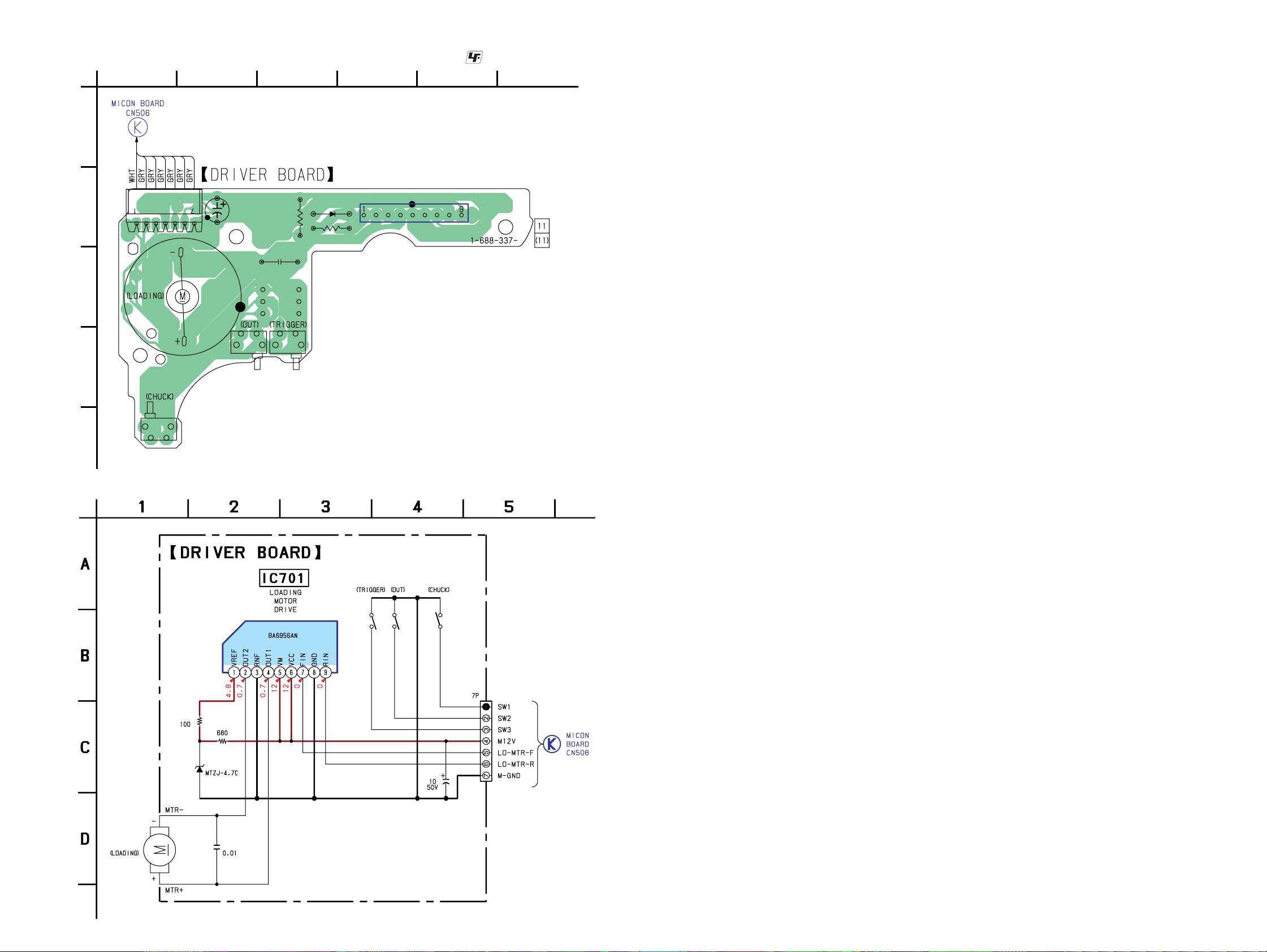
6-4. PRINTED WIRING BOARD — DVD MECHANISM SECTION (2/2) — • Refer to page 36 for Circuit Boards Location and page 37 for Common Note on Printed Wiring Boards.
: Uses unleaded solder.
CX-VX5
A
B
C
D
1
M701
CN701
S702
(Page 58)
23456
R701
D701
R702
IC701
C711
S701
C705
S703
E
6-5. SCHEMATIC DIAGRAM — DVD MECHANISM SECTION (2/2) — • Refer to page 37 for Common Note on Schematic Diagrams.
S703 S701 S702
IC701
CN701
R702
R701
D701
C711
(Page 59)
M701
C705
41 41
Page 17
CX-VX5
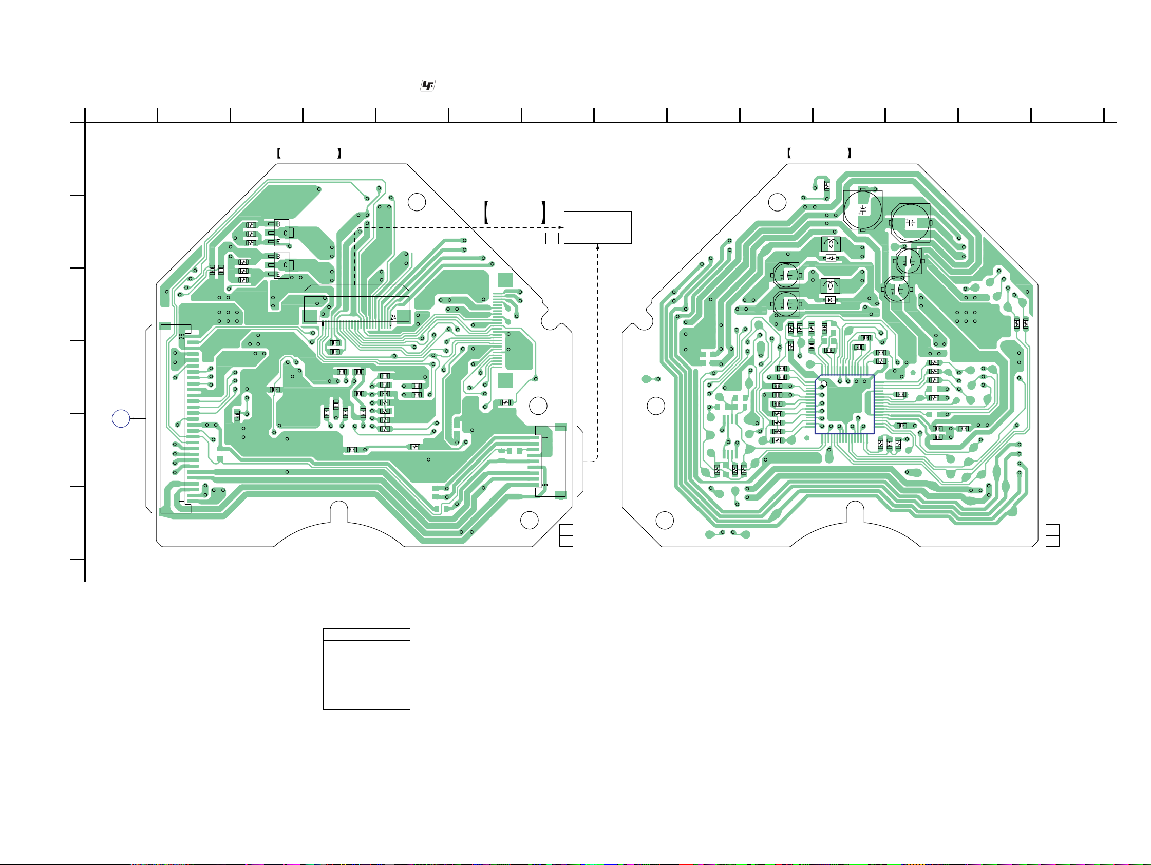
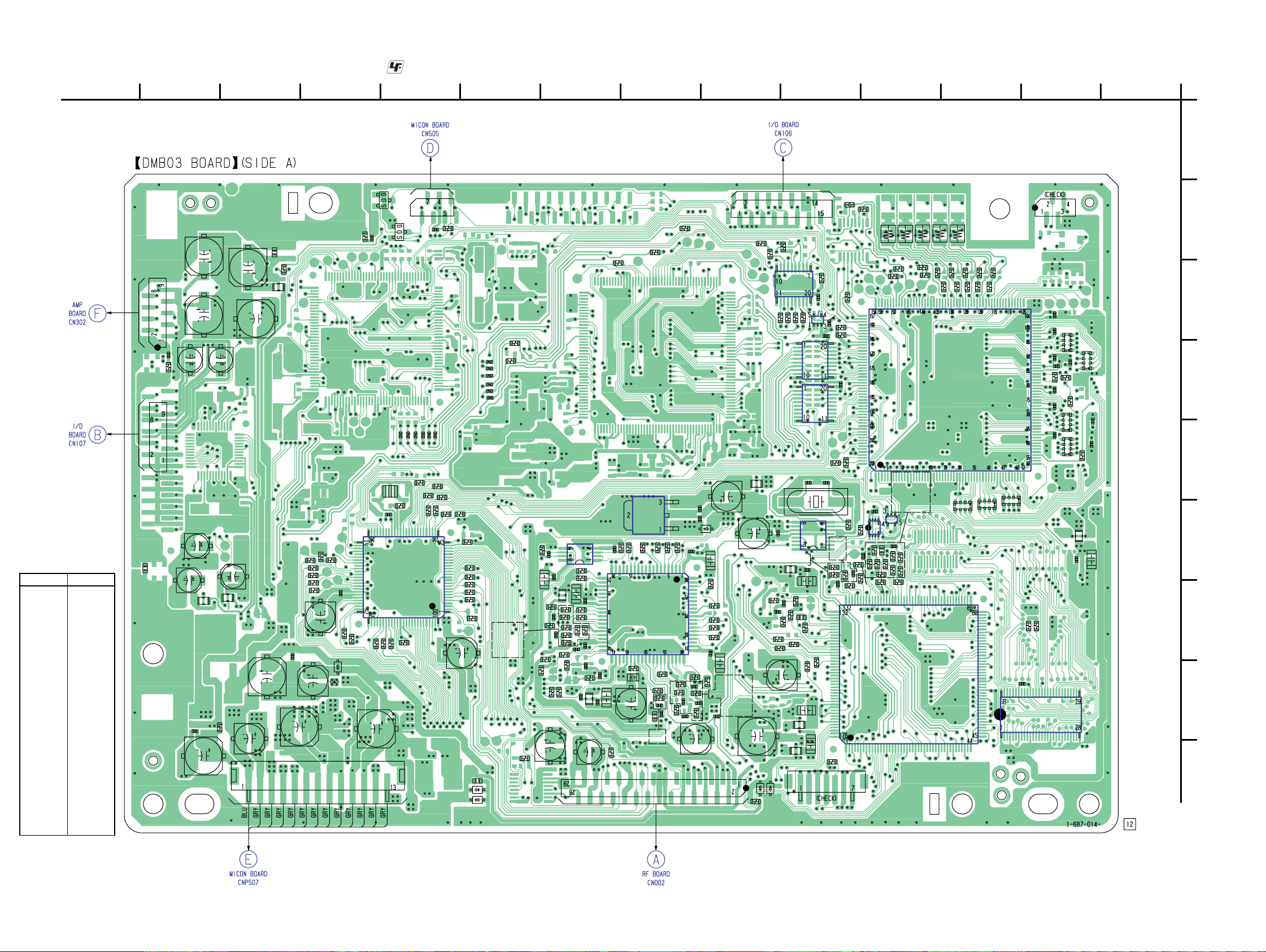
6-6. PRINTED WIRING BOARD — DMB03 SECTION (1/2) — • Refer to page 36 for Circuit Boards Location and page 37 for Common Note on Printed Wiring Boards.
: Uses unleaded solder.
(Page 65)
(Page 52)
• Semiconductor
Location (Side A)
Ref. No. Location
D202 F-6
D901 H-11
D1801 I-6
D1802 I-6
D1805 I-9
D1806 I-9
IC207 D-3
IC211 F-7
IC216 H-2
IC255 C-5
IC256 D-5
IC258 D-5
IC259 C-5
IC503 F-8
IC509 G-7
IC701 H-4
IC901 F-10
IC902 F-4
IC904 F-4
IC906 F-5
Q903 B-11
Q904 B-10
R1303
CN106
R1302
CN107
C1302
C345
C393
C356
C346
C355
FL333
C394
C352
C343
FL332
JW392
C364
C357
C392
C366
FL352
R1301
C926
R329
R995
R994
R917
R988
R916
C101
C927
C903
CN102
R984
C925
R997
C904
R992
D901
R991
R1304
Q903
C151
C1304
C905
R907
X901
R906
R971
IC901
R905
JW601
R978
Q904
JW602
JW604
R923
CN101
C924
JW603
R910
JW605
R940
R973
JW606
R976
(Page 58)
R970
R921
R942
R943
C901
R964
R962
JW801
R947
R948
R949
R919
R958
R1803
D1806
D1805
JW803
JW802
JW804
JW805
JW806
R550
R552
R563
R564
R523
R9993
R9994
R577
R751
R578
R511
R506
R505
R504
C517
C588
C590
C528
R560
R510
R507
C502
C518
R561
FL502
R558
IC503
C533
C534
C545
C544
R562
C592
R548
R545
C543
R551
R559
C531
FL501
C535
C561
R805
C522
C556
R536
R599
R584
C558
R583
IC211
R544
IC509
C547
R222
R588
C551
R593
C548
CN501
R539
R566
R540
C573
R567
R221
R538
C560
C567
R572
C526
C215
D202
R501
R576
R575
C214
R698
C569
C552
C553
C213
R694
R568
R565
C568
C570
C559
C565
R571
C563
R601
FL206
C916
C781
R1810
R327
R767
R759
D1801
R757
R296
C771
CN105
R9985
FL701
R762
D1802
R197
IC259
C917
C702
R758
C701
FL703
(Page 53)
R9982
R9983
R9984
X902
R707
R708
C706
R765
C774
C773
R769
R799
C779
FL702
IC255
IC906
R763
C284
IC256
IC258
C915C914
CN901
C287
R756
C780
R975
R198
R231
C283
C286
R709
R218
R285
R710
C708
R234
R927
C711
R254
R217
R230
C907
R931
C715
R711
IC904
R712
R269
R747
IC902
R719
L403L402
R226
R748
R713
R715
C716
R714
IC701
R781
C717
R225
R268
R717
R716
R718
R780
234567891011121314
1
A
CN202
L406
L405L404
R263
R264
R265
R267
R266
R276
R277
R274
R273
R275
C241
RB17
C242
C246
C245
RB16
R15
R13
C239
C227
R213
FL204
IC207
RB18
RB19
RB20
C248
C253
R14
C252
RB13
C261
RB12
B
C
D
E
F
C258
C259
G
H
C315
R215
R250
IC216
I
(Page 58)
(Page 39)
4242
Page 18
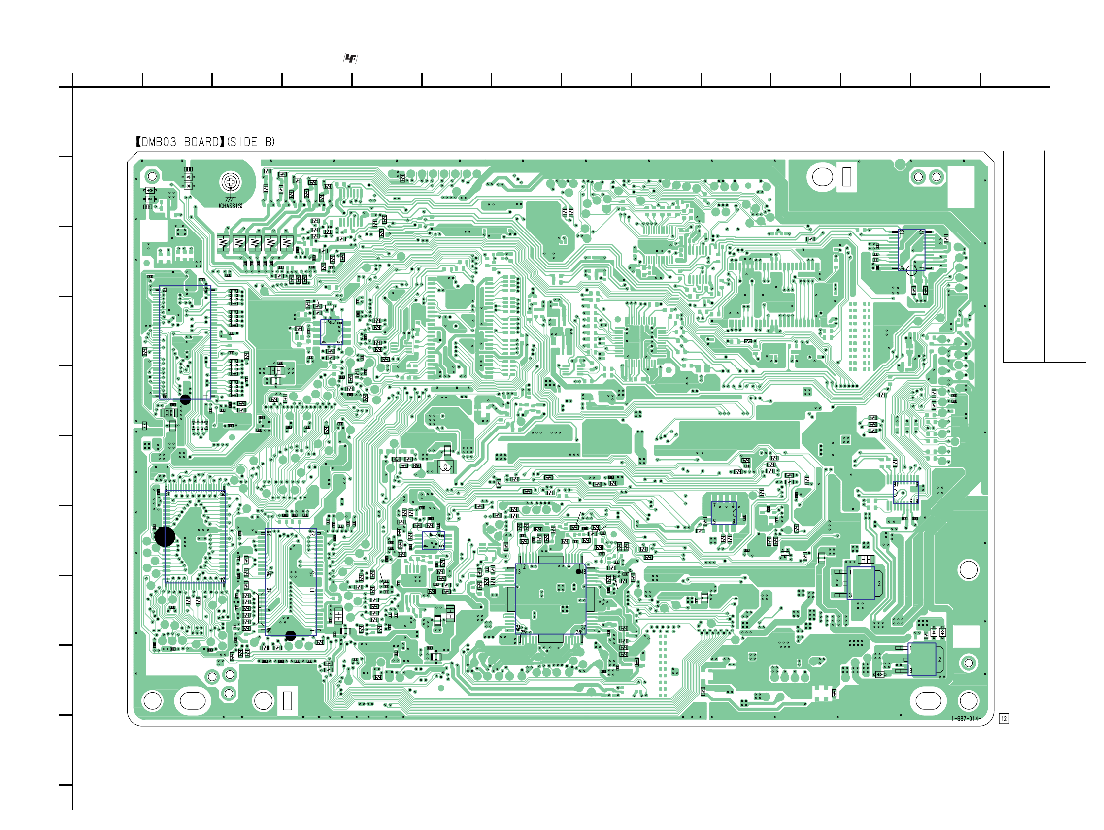
6-7. PRINTED WIRING BOARD — DMB03 SECTION (2/2) — • Refer to page 36 for Circuit Boards Location and page 37 for Common Note on Printed Wiring Boards.
: Uses unleaded solder.
CX-VX5
A
B
C
D
E
F
G
H
1
234567891011 12 13 14
• Semiconductor
Location (Side B)
R282
L414
C233
R742
C232
R12
C235
C270
C272
R730
R731
R732
R9987
C265
C760
C416
C231
R245
L413
R736
R737
C230
R733
R734
R281
C415
C237
R207
C266
R735
R9986
C761
L412
FL205
C414
R257
C762
R280
C229
R283
R243
C257
C268C269
C413
R271
R284
IC706
C273
R261
C718C722C723
C763
R328
R233
R279
R240
R744
C226
R251
C204
R227
R248
R294
R1000
R253
R232
C714
R278
C412
R219
Q202
C216
C725
R255
C724
R745
R228
R260
C236
IC204
C713
R746
C712
C726
C262
C267
C727
R259
R246
C752
R778
C764
C244
C247
R752
FL705
C251
R244
C709
R770
R776
C256
R777
R272
R9998
C260
R247
R766
R908
R220
C775
C772
C768
C770
R755
R754
R753
R750
R9999
R9980
R9981
FB902
R724
C769
C767
C766
R293
R270
C765
C777
R932
R720
R721
R764
R201
R725
C778
C705
R933
FB903
R700
R784
C703
R726
C720
C728
R728R727
C782
R786
R789
C783
C776
FL706
FL903
L901
C721
R785
FL704
IC703
R787
R788
C729
R9988
R581
R543
R699
C519
R547
R502
R573
R580
R589
R508
R695
C514
R579
R533
R587
R696
R532
R534
C512
R529
R541
R585
IC501
R530
R531
R528
R223
C510
R224
R517
C508
R522
R537
R524
R527
C509
C516
C501
C589
R513
C525
C529
R503
R525
C506
R516
R512
C504
C527
R520
R519
R535
R555
R597
R554
R553
C503
R586
R592
R521
R918
C902
R615
R913
FL901
IC903
R901
R935
C910
R904
JW607
R902
C906
C918
R930
R926
R925
R996
C908
R911
C909
Q901
R990
R920
R912
C913
R915
R998
R974
R335
FL908
R1101
R311
R312
C367
C368
C928
IC907
R310
R319
D392
C363
C365
R342
IC331
C342
IC352
R353
C344
R392
IC392
R308
R309
R362
R352
C308
C309
D393
D394
R1202
IC203
IC206
R214
RB21
D1203
D1204
C250
R262
C281
C263
L416
C218
C238
C243
C240
C271
RB15
RB14
RB11
RB10
R741
L415
C220
C741
C742
C743
C744
C745
C234
R11
R10
C730
C740
R738
R743
D1202
D1201
R1201
C249
R301
R1802
C264
C255
C205
C275
C254
FL203
C316
C282
I
Ref. No. Location
D392 I-12
D393 H-13
D394 H-13
D1201 B-2
D1202 B-1
D1203 B-2
D1204 B-2
IC203 D-2
IC204 D-4
IC206 G-2
IC331 F-12
IC352 C-12
IC392 I-13
IC501 H-7
IC703 G-6
IC706 H-4
IC903 G-10
IC907 H-12
Q202 D-4
Q901 G-11
J
43 43
Page 19
CX-VX5
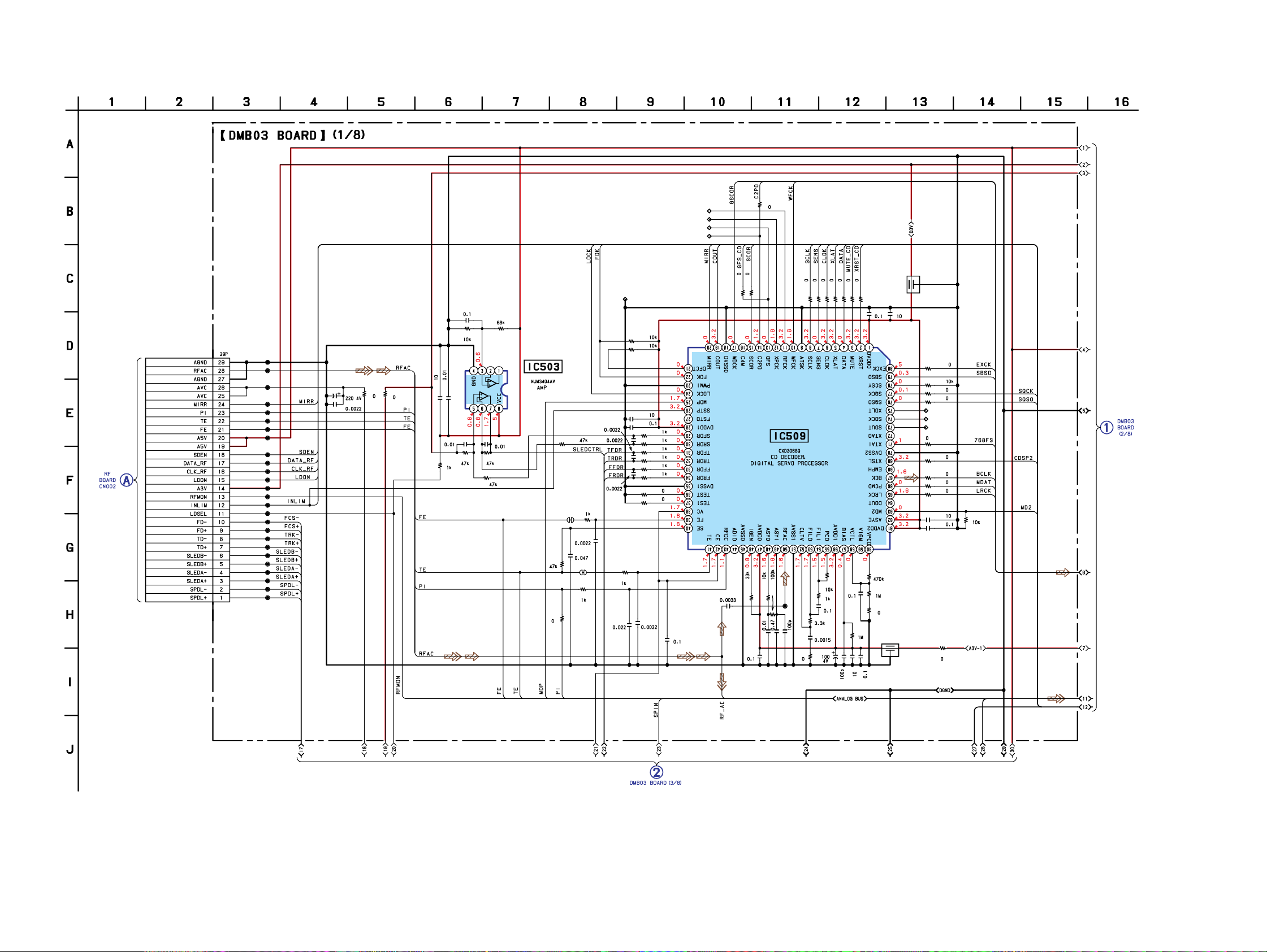
6-8. SCHEMATIC DIAGRAM — DMB03 SECTION (1/8) — • Refer to page 37 for Common Note on Schematic Diagrams.
(Page 40)
CN501
CL544
CL537
CL536
CL535
CL531
CL530
CL529
CL527
CL526
CL525
CL524
CL523
CL522
CL509
CL510
CL511
CL512
CL513
CL514
CL515
CL516
CL517
CL518
CL519
CL520
CL521
C592
C516
R592
R555
C517
C501
R599
C518
C522
R536
R503
R506
R504
R537
C502
IC503
R558
R507
R505
SL501
C533
C531
SL502
R561
R560
C588
C589
C590
C534
CL501
R562
R545
R548
C545
C543
C535
R550
R551
R552
R559
R563
R564
R578
R577
C544
CL505
CL504
CL503
CL502
C553
R585
C547
R583
R584
R587
R588
C548
R593
C551
IC509
CL528
C573
R601
R544
R567
R541
C560
R565
C559
C558
R540
R566
R539
R538
R508
C565
R568
R502
C567
R572
R571
C552
FL501
FL502
C568
R698
R9988
R694
R695
R696
CL508
CL507
CL506
R699
R501
R576
R575
C570
C569
(Page 45)
R573
R615
(Page 46)
4444
C563
C556
C561
Page 20
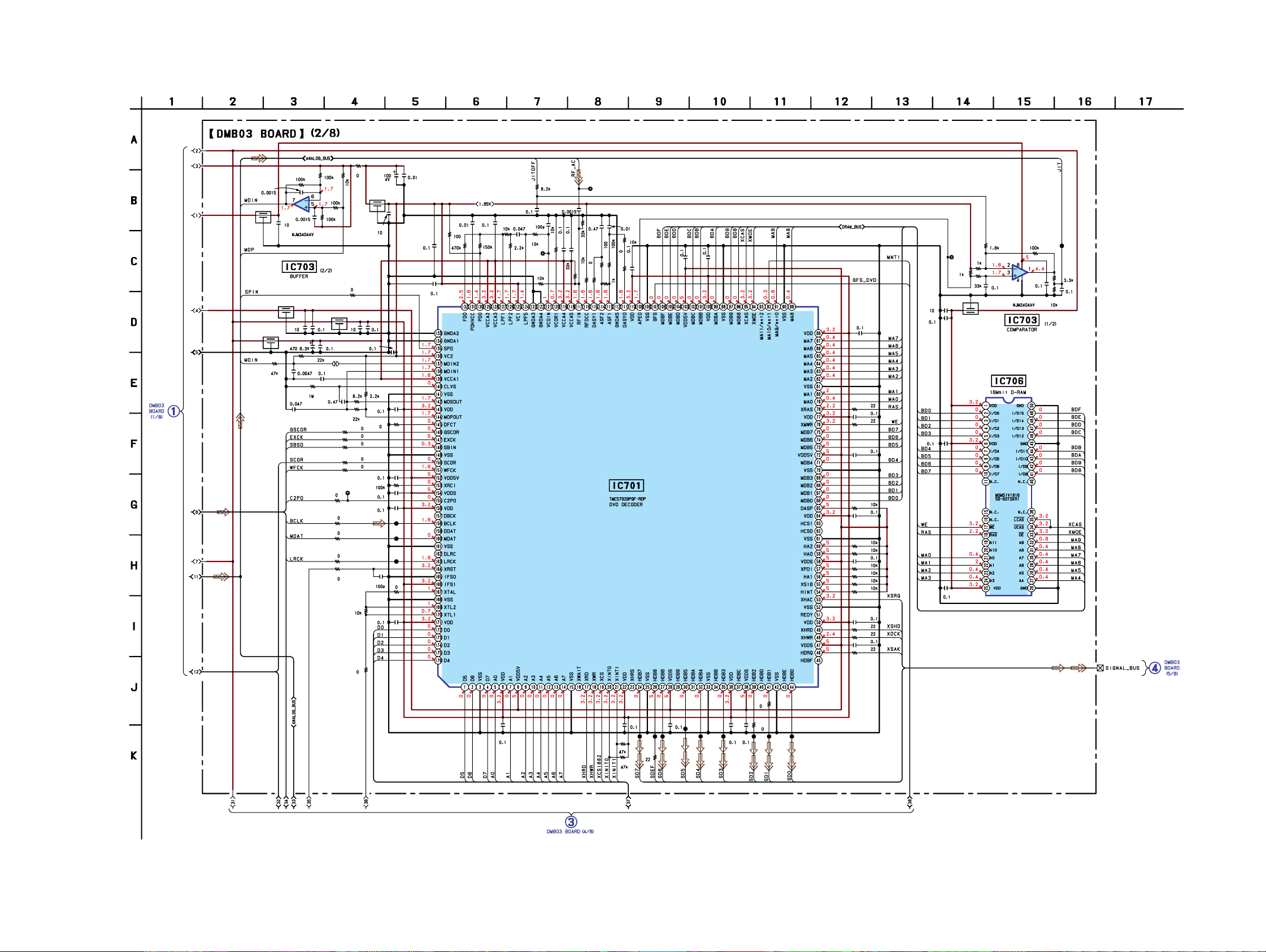
6-9. SCHEMATIC DIAGRAM — DMB03 SECTION (2/8) — • Refer to page 37 for Common Note on Schematic Diagrams.
R784
C782
FL706
C729
FL703
FL704
R767
R786
R787
R788
R789
C783
IC703(2/2)
R751
R765
C772
FL702
C776
SL703
C780 C779
C781
C774
R785
C775
FL701
C778C777
C702
C701
C705
C706
C752
R708
R707
C708
C709
R709
R710
C711
R711
C703
R712
CL703
C712
R714
R700
R713
C715
C713
C714
R747
TP703
C716 C717
R748
R716
R781
R715
R717
R719
R780
R718
C718
C722
C723
C730
C727
C724
CL701
R720
FL705
R724
R721
C720
IC703(1/2)
CX-VX5
R726R725
TP701
R727
C721
C728
R728
(Page
44)
R764 R763 R769
C771
C773
R755
R754
R753
R752
R799
R759
R758
R757
R756
R766
R762
CL791
R750
R777
C770
R770
C769
R778
C768
C767
C766
C765
CL787
CL786
CL785
R776
IC701
R9987
R730
C740
R731
C741
R732
C742
R733
R734
C743
R735
R736
R737
R738
C744
R741
R742
C745
R743
C725
IC706
C726
(Page 48)
C764
(Page 47)
C763
R745
R746
R744
CL778
CL777
CL776
C762
CL775
CL774
45 45
CL773
C761
C760
R9986
CL772
CL770CL771
Page 21

CX-VX5
6-10. SCHEMATIC DIAGRAM — DMB03 SECTION (3/8) — • Refer to page 37 for Common Note on Schematic Diagrams.
(Page 44)
JL521
C527
C526
IC501
R543 R547
R580
R581
C519
R589
R533C514
R529C512
R527C510
R522C509
R579
R534
R532
R530 R531
R528
R525
R524
R521
R523
R586
R519
R535
D901
C928
C926
C927
C925
(Page 47)
(Page 50)
(Page 48, 49, 50)
(Page 50)
IC907
(Page 49)
R597
R510
R511
C529
C528
R554
R553
R513
C525
C504
R512
C503
R520
C506R516
R517
C508
C151
C101
CL931
CL932
CL933
CL936
CL935
CL937
CL939
CL940
CL941
CL942
CL943
CN102
R1101
(Page 49)
(Page 59)
(Page 49)
4646
Page 22

6-11. SCHEMATIC DIAGRAM — DMB03 SECTION (4/8) — • Refer to page 37 for Common Note on Schematic Diagrams and page 38 for Waveforms.
(Page 45)
CX-VX5
(Page 59)
(Page 46)
CN101
CL906
CL907
CL908
CL909
CL910
C924
IC903
R970
Q903
Q904
R913
C918
FL901
C901
R958
R918
R964
C902
R919
R949
R948
R947
JL910
JL911
R962
R901
R943
R902
R942
R976
R973
R921
R910
R940
IC901
X901
C906
C910
R971
R978
R905
C905
R906
R930
R907
R911
R912
R926
R925
R904
Q901
R935
C904
CL922
JL967
JL966
JL965
CL934
JL957
JL956
C903
C908
R920
R990
R923
R991
R992
R915
R974
R988
R917
R994
R995
R996
R997
R998
C909
FL908
R984
R916
C913
FL903
L901
C917
R908
R975
IC902
IC904
C916
C915
C914
C907
CL954
CL959
CL955
CL950
CL951
CL952
CL953
X902
CL905
R931
R927
CN901
IC906
CL904
FB902
CL913
FB903
R932
R933
47 47
(Page 48)
Page 23

CX-VX5
6-12. SCHEMATIC DIAGRAM — DMB03 SECTION (5/8) — • Refer to page 37 for Common Note on Schematic Diagrams.
(Page 45)
(Page 47)
R270
(Page 50)
CN202
(Page 49)
C283
C284
IC256
IC258
IC255
R9998
R9999
R9980
R9981
R223
R217
R9994
R224
R221
R220
R218
R9993
R222
R219
CL208
CL209
R281R280R279R278
C415C414C413C412
CL207
CL204
CL206
L402 L403 L404 L405 L406
CL210
R282
C416
CN105
(Page 55)
R201
(Page 46, 49, 50)
D1203
D1204
R1202
D1202
(Page 49)
(Page 50)
R296
R294
R197
R293
C286
C287
R198
IC259
R9982
R9983
R9984
R9985
(Page 50)
L412 L416L415L414L413
R1201
D1201
(Page 49)
4848
Page 24

6-13. SCHEMATIC DIAGRAM — DMB03 SECTION (6/8) — • Refer to page 37 for Common Note on Schematic Diagrams.
(Page 48)
CX-VX5
(Page 46)
(Page 50)
(Page 46)
(Page 46, 48, 50)
(Page 46)
(Page 48)
R1810
D1801
D1802
R1803 R1303
D1805
D1806
R1802
C1304
C392
R1304
IC392
R392
D392
C393
D393
C394 JW392
D394
R1301
FL352
JW801
JW802
JW803
JW804
JW805
JW806
JW601
JW602
JW603
JW604
JW605
JW606
JW607
R310
R311
R312
R342
IC331
R319 R309
C342
FL332
C346
JL304
C343
JL303
C345
C344
FL333
R308
C308 C309
R1302
C1302
CL302
CL303
CL304
CL305
CL306
CL307
CL308
CL316
CL317
CL318
CL319
CL320
CL322
CL321
CL323
CN106
(Page 66)
CN107
(Page 54)
(Page 48)
R327
C364 C363
C366 C365
R328
R329
C367
C368
R335
IC352
R362
C355
C352
R352
C357R353
C356
49 49
Page 25

CX-VX5
6-14. SCHEMATIC DIAGRAM — DMB03 SECTION (7/8) — • Refer to page 37 for Common Note on Schematic Diagrams and page 38 for Waveforms.
(Page 48)
R269
JL211
JL210
R1000
JL209
JL208
C273
R268
R225
R226
R228
C226
C229
R233
JL207
R284
R283
R207
R263 R264 R265 R266 R267
C237
C230 C231 C232 C233 C234
R273
R274
R275
R276
C238C236
R277
(Page 48)
R251
R259
R260
JL215
JL214
JL213
R261
JL212
JL206
JL205
JL204
(Page 49)
JL203
(Page 48)
CL254
C257
R243
R240
CL257
CL252
C204
CL255
IC204
CL253
Q202
CL251
R805
CL256
C256
R255
R244
R247
R230
R231
R253
R234
R254
C247
C260
C216
C262
R227
R248
JL216
C244
C251
R246
R285
R272
R271
JL217
JL218
IC207
R12
R15
R14
R13
R213
C241
C242
C248
C252
C253
(Page 51)
C261
C263
(Page 46)
(Page 46, 48, 49)
(Page 46)
IC211
FL205
C266
C265
D202
FL206
C213
C215C214
C267
R232
C268
C269
R257
R245
C270
C272
RB18
C271
RB20
RB19
JL202
R10
R11
RB21
(Page 51)
5050
Page 26

6-15. SCHEMATIC DIAGRAM — DMB03 SECTION (8/8) — • Refer to page 37 for Common Note on Schematic Diagrams.
C255
FL203
FL204
C258
C259
C205
RB10
RB11
CX-VX5
IC203
C218
RB12
C220
C227
RB13
C235
(Page 50)
C282
C281
CL390
CL389
CL388
CL387
CL386
CL385
CL384
CL383
CL382
CL381
CL380
CL379
CL378
CL377
CL376
CL375
CL374
CL373
CL372
CL371
IC216
CL350
CL351
CL352
CL353
CL354
CL355
CL356
CL357
CL358
CL359
CL360
CL361
CL362
CL363
CL364
CL365
CL366
CL367
CL368
CL369
CL370
C315
C316
C275
R214
R262
R250
R215
IC206
C264
C254
RB14
RB15
C239
C240
R301
C243
RB16
C245
C246
RB17
C249
C250
(Page 50)
51 51
Page 27

CX-VX5
6-16. PRINTED WIRING BOARDS — I/O SECTION (1/2) — • Refer to page 36 for Circuit Boards Location and page 37 for Common Note on Printed Wiring Boards.
: Uses unleaded solder.
• Semiconductor
Location (Side A)
Ref. No. Location
D103 G-4
D201 F-11
D203 F-10
D281 E-12
D282 E-12
IC102 D-12
IC106 F-8
IC107 E-11
IC110 G-10
Q102 D-10
Q140 H-3
Q141 H-3
Q142 H-4
Q143 G-8
Q145 G-8
Q146 E-13
Q147 E-12
Q202 D-10
Q205 E-11
Q206 E-12
R294
R281
Q146 Q147
R188
R231
R229
C194
R248
R198
C202
IC102
R295
R297
R258
D282
Q206
R293
D281
R290
R221
C108
R195
Q205
R227
R112
R194
D201
R127
R247
IC107
D203
Q102 Q202
R110
R210
C197
R264
C205
R207
L101
R261
C156
C105
R208
R206
R108
C206
R107
C106
R106
L102
R134
R265
R266
R196
C132
234567891011121314
1
A
B
C
D
E
F
R259
R205
R245
CN101
IC110
R272
CN107
FC902
(Page 58) (Page 42)
IC106
Q143
R149
R144
R148
R146
Q145
C174
R176
C198
L122
C192
L115
C167
C201
L121
C200
L117
C219
C227
L118
D103
Q142
L116
C228
C229
R190
R191
L113
L120
Q141
C207
C218
G
Q140
H
L114
I
L119
J
5252
Page 28

6-17. PRINTED WIRING BOARDS — I/O SECTION (2/2) — • Refer to page 36 for Circuit Boards Location and page 37 for Common Note on Printed Wiring Boards.
: Uses unleaded solder.
CX-VX5
A
B
C
D
E
F
G
H
1
234567891011 12 13 14
J101
J104
• Semiconductor
Location (Side B)
Ref. No. Location
D202 H-11
C130
R64
R165
R180
R177
R179
CN104
R181
C131
R175
R161
R197
R189
R199
R167
IC103
C161
C144
R139
R138
CN110
CN109
C142
C157
C140
L111
L112
C249
EP103
C158
C180
C173
C153
R169
C187
C252
IC104
C168
C190
C181
R267
C248
IC109
R239
C183
C162
C261
C184
R162
R163
C189
R158
R268
C191
R121
C159
C258
C110
R119
C120
R152
C210
R217
R117
C111
CN108
R136
C163
C182
C211
IC105
R151
R219
C259
R114
R278
R174
R257
R113
R277
R292
C154
R274
C104
R211
R214
C204
Q201
C278
C107
C271
C185
R204
C150
R111
R115
R128
C220
R202
R275
R213
R270
R116
R203
R234
C247
C151
R285
C112
R120
R216
R102
R104
C230
C272
C203
R103
C273
R118
C186
R273
D202
R286
C109
R250
R252
C152
R215
R129
C209
Q101
C178
R220
R296
R218
C103
R105
C199
R192
C244
R283
R154
C212
C208
C196
R226
C251
R212
R153
R126
R291
IC108
C246
C245
C226
R233
R230
R284
X201
C195
CN105
R237
R238
R254
R170
R168
CNP102
R140
R142
C148
R182
R183
R185
R184
R187
R186
Q139Q138
Q137
C169
R193
IC103 G-5
IC104 D-8
IC105 E-9
IC108 E-12
IC109 F-8
Q101 F-11
Q137 H-4
Q138 H-3
Q139 H-3
Q201 F-10
TM101
C260
C193
C170
C250
C172C171
I
CN106
FC903
(Page 56)
J
(Page 42)
53 53
Page 29

CX-VX5
6-18. SCHEMATIC DIAGRAM — I/O SECTION (1/2) — • Refer to page 37 for Common Note on Schematic Diagrams and page 38 for Waveforms.
J104
L101
L102
R152
R134
R283
R285
R284
R286
C150
C152
C151
R136
R151
R153
R154
R158
C208
R112
C108
R212
C185
IC107
R120
R220
R219
R119
R118
C112
R218
C212
R217
C211
R117
C111
C109
C209
C210
C110
C197
Q146
R195
R194
R116
R115
R216
R215
R214
R213
R114
R113
R198
IC102
D281
R248
C196
D282
Q206
Q147
R295
R294
R188
C202C186
C195
C194
R297 R293
Q205
R281
R291
IC108
R296
R231
R229
R290
C199
R127
R126
X201
R247
R250
D201
R227
R226
C226
C245
C246
R257
R258
R245
R277
R278
D203
C258
C261
C244
R221
R267
C259
D202
R268
R266
R265
C251
R259
R230
R233
R238
R237
R254
CN105
TM101
CN101
(Page 59)
(Page 57)
CN108
C120
EP103
R121
Q102
Q202
R111
R110
R210
R211
C156
C159
R163
C107
IC105(2/2)
C162
R162
C168
C154
IC105(1/2)
C163
R261
R264
C105
R108
C106
C206
R208
C205
R107 R174
R106
R206
R274R207
(Page 55)
C204
C104
C103
R129
R105
Q101
R205
Q201
R192
C203
R128
R292
C247
C278
IC110
R204
C178
R104
R234
R252C230
C220
R202R203
CN107
R270
R275
R273
R272
R102R103
C271
C272
C273
FC902
(Page 49)
5454
Page 30

6-19. SCHEMATIC DIAGRAM — I/O SECTION (2/2) — • Refer to page 37 for Common Note on Schematic Diagrams.
CX-VX5
(Page 54)
J101
R167
R170
R175
R197
R161
R189
R164
R199
R179
R165
R177
R180
R196
C131C130
R168
C132
CN110
CNP102
CN104
CN109
C169
C167
R140
R142
R139
R138
L111
C148
C144
C142
C140
C153
IC104
IC103
R176
R169
C158
C173
C174
C157
C161
C170
C171
R148
R146
C172
Q145
Q143
R144
R149
C180
IC106
C181
C184
C187
C189 C190
C193
C191
C183C182
Q138
R181 R187
R186
C252
IC109
C249
Q139
Q140
L112
C260
C248
C250
L115 L122
C198C192
L117 L121
C200 C201
L114 L119
C207 C218
L116 L118
C219 C227
L113 L120
C228 C229
R191
CN106
FC903
(Page 48)
R239
R185
R184
R183
R182
D103
R193
Q137
Q141
Q142
R190
55 55
Page 31

CX-VX5
6-20. PRINTED WIRING BOARD — F-AV SECTION — • Refer to page 36 for Circuit Boards Location and page 37 for Common Note on Printed Wiring Boards.
: Uses unleaded solder.
• Semiconductor
Location
Ref. No. Location
D809 B-1
D810 B-2
D811 G-7
D812 B-5
D813 B-5
IC803 H-3
IC804 G-6
Q803 F-3
Q804 E-2
Q805 F-3
Q806 F-2
Q807 H-6
A
B
C
D
1
C843
D809
2345678910
R843
R842
C854
C852
D810
C867
D813
D812
R827
R874
C873
C872
E
F
G
H
FB811
C842
R831
FB805
C840
R830
C839
FB806
J801
Q806
L805
C862
R848
C860
Q804
R847
R852
L804
C841
C865
R853
C859
R871
R828
R829
R856
C863
R851
C838
FB804
R850
R854
Q805
R849
C864
FB808
C858
J803
Q803
IC803
R870
C857
R869
C861
R846
C853
FB809
R867
R855
R845
C866
C856
C855
FB807
J802
FB810
C849
R838
EP801
R844
C851
C846
R837
R841
IC804
Q807
R839
R840
R836
J804
C847
C850
R857
C848
R862
R826
D811
C878
R825
CN805
R861
CNP802
R865
R833
CNP804
R866
(Page 65)
R832
EP802
R872
R873
R863
I
(Page 60) (Page 53)
J
5656
Page 32

6-21. SCHEMATIC DIAGRAM — F-AV SECTION — • Refer to page 37 for Common Note on Schematic Diagrams.
CX-VX5
J801
J802
J803
FB810
FB811
D810
FB805
R869
FB809
C841
D809
EP801
R867
FB806
C843
FB807
FB808
R856
C866
R855
C840
C842
C865
L804
L805
C860
C861
C862
R829
R831
C863
C864
R853
R852
C859
R854
C838
R828
Q805
Q806
R830
C839
R850
R851
R847R848
R849
R871
C858
R870
Q803
Q804
R846
C857
IC803(1/2)
R845
FB804
R844 R843
IC804
CN805
R825
R826
R827
(Page 61)
CNP804
R832
R833
C852
R842
C855C856
C854
IC803(2/2)
C853
C851
C849
R838
Q807
C850
R841 R840
R836
R839
R837
C846
C878
D811
C847
C848
(Page 66)
J804
C867
D812
D813
R857
C873C872
EP802
R874
R861
R865
R862
R866
R863
R872
R873
CNP802
(Page 54)
57 57
Page 33

CX-VX5
6-22. PRINTED WIRING BOARD — MICON SECTION — • Refer to page 36 for Circuit Boards Location and page 37 for Common Note on Printed Wiring Boards.
: Uses unleaded solder.
A
B
C
D
E
F
G
H
1
234567891011 12 13 14
(Page 52) (Page 65)
EP504
C534
D516
D517
R604
C562
Q517
R603
R602
R640
FB501
D515
D514
R525
C509
C508
C507
D510
R522
R521
R519
R517
R515
R513
D511
R540
R541
R549
R526
D503
C519
R528
R524
R511
C512
R591
Q505
R592
C554
R585
R631
R594
Q506
C533
R595
Q504
R613
C550
R542
R543
R574
R643
R553
R611
C555
R554
R555
R556
R614
R635
R636
D513
R612
Q515
R579
R577
D512
Q514
R575
R576
R530
CN505
C557
D518
D519
(Page 42)
D520
D521
EP503
CNP501
R580
R548
R564
CN503
R578
R532
R642
CN511
R572
R531
R641
R639
R570
R552
C528
R568
R551
C547
R571
CN502
R569
R565
R566
CLP503
Q507
C525
C517
R550
IC501
R544
R637
R567
IC502
R560
R634
R633
C523
C520
R539
R538
R505
R559
R557
C515
R628
R507
R506
R593
C527
R558
C526
D506
R562
R632
FB502
R516
R514
CN510
R596
D505
R638
R563
R561
C511
R510
R503
Q501
R597
R512
R573
R630
R520
R536
X501
C551
R518
CN501
R598
IC506
CN512
C513
R629
R583
Z1
C510
R504
C514
R533
R534
C529
C543
C542
R502
Q508
C537
C530
R581
R501
R582
C539
Q503
CLP502
R586
L501
R584
IC505
D502
D501
C544
C545
L503
C540
R608
C541
R605
C521
R607
C546
C538
R508
CNP507
CN508
R545
R606
CN506
CLP501
EP502
(Page 42)
CLP504
(Page 69)
(Page 69)
CN509
C561
EP501
(Page 41)
I
• Semiconductor Location
Ref. No. Location
D501 H-12
D502 H-12
D503 I-4
D505 C-11
D506 D-10
D510 D-3
D511 D-3
Ref. No. Location
D512 D-6
D513 D-6
D514 E-2
D515 E-2
D516 B-1
D517 B-1
D518 H-6
Ref. No. Location
D519 H-6
D520 C-8
D521 C-8
IC501 G-10
IC502 D-10
IC505 D-12
Ref. No. Location Ref. No. Location
IC506 C-11
Q507 C-10
Q508 B-12
Q501 H-10
Q503 G-12
Q504 E-5
Q514 H-6
Q515 H-6
Q517 E-2
Q505 F-4
Q506 F-4
5858
(Page 60)(Page 62)(Page 60)
Page 34

6-23. SCHEMATIC DIAGRAM — MICON SECTION — • Refer to page 37 for Common Note on Schematic Diagrams and page 38 for Waveforms.
CX-VX5
(Page
(Page
(Page
(Page
(Page
(Page
54)
47)
61)
63)
61)
66)
CN511
CN505
CN503
CN502
CN501
CN510
R565
R566
R569
R568
R567
R570
R576
R572
R530
R531
R575
R532
R577
R578
R579
R580
R636
R635
D513 D512
R507
R506
R505
D503
R504
R503
FB501
R501
R502
R591
R592
R593
R594
R595
R596
R597
R598
Q515
C550
R628
R571
R574
R629
D501
C551 C510
3
7
1
4
6
5
R
C
1
1
TP548
5
C
R630
CNP501
EP503
C557
8
9
1
51
5
D
D
R511
R513
R515
R517
R519
R521
R522
R526
R528
R524
TP545
TP546
TP547
R510
D502
R525
R512
R514
R516
R518
R520
EP501
C519
C507
C508
C509
Q514
C538
CNP507
D517
D516
R508
D521
D520
R545
R608
R607
R606
R605
C546
(Page 46)
CN508
(Page 70)
EP504
CN509
C561C562
C521
R602
R640
R603
EP502
CN506
(Page 70)
(Page 41)
CN512
L503
R612
R614
R611
IC501
2
6
0
3
5
5
B
F
R
2
1
5
C
C513
C514
X501
R564 R548
2
1
3
3
6
6
R
R
R643
R583
C534
C530
Q504
C554
R544
R555
C555
R554
TP544
R553
TP543
C517
D515
D514
R560
C520
R549
R642
R556
R641
TP542
R639
C528
TP541
R552
R551
R550
9
3
5
R
3
3
8
6
5
3
R
1
5
5
R
C
R542
R543
R585
7
4
3
3
6
6
R
R
C533
Q506Q505
R541
R540
R557
R584
Q508
R586
R582
R559
R558
R581
C545 C544
C541
R561
R562
IC502
C523
R533
C529
Q507
D505
D506
IC506
C542
C543
IC505
C540
D511
D510
R563
R573
C527
C526
R638
C525
Q503
R534
Q501
L501
C537
C539
R604
Q517
59 59
Page 35

CX-VX5
6-24. PRINTED WIRING BOARDS — KEY SECTION — • Refer to page 36 for Circuit Boards Location and page 37 for Common Note on Printed Wiring Boards.
: Uses unleaded solder.
A
B
C
D
E
1
S802
D801
234567891011 12 13 14
R801
C801
R802
C802
CN806
CNP801
IC801
S812
S813
R813
S808
S810
R807
R812
S806
R808
S811
R810
R806
S809
S805
R809
R805
S807
S804
(Page 58)
CN803
R811
S801
C805
C806
CN804
CN801
FB801
(Page 58)(Page 56)
F
R804
6060
Page 36

6-25. SCHEMATIC DIAGRAM — KEY SECTION — • Refer to page 37 for Common Note on Schematic Diagrams.
D801
CX-VX5
CN804
(Page 57)
CN801
S801
R805
IC801
C806
C805
S804
CNP801
R804
R811
CN806
S810
C802
CN803
R801C801
S802
FB801
(Page 59)
R802
(Page 59)
R806
R807
R808
R809
R810
S805
S806
S807
S808
S809
R812
S811
S812
R813
S813
61 61
Page 37

CX-VX5
6-26. PRINTED WIRING BOARD — FL SECTION — • Refer to page 36 for Circuit Boards Location and page 37 for Common Note on Printed Wiring Boards.
: Uses unleaded solder.
A
B
C
D
1
234567891011 12 13 14
D803
C824
C825
C826
C827
C830
C828
JR802
JR801
C829
C831
JR804
C832
C833
C834
C835
IC802
C816
R820
R822
R821
C818
C819
C820
R815
D806
L801
D807
D802
E
F
G
H
D814
D815
R824
FL801
C821
JR805
C817
C815
C814
D808
D804
C813
D805
R868
R816
T801
C812
Q802
R814
Q801
C811
JR806
(Page 58)
FB802
R823
CN802
FB803
R819
R817
R818
S803
• Semiconductor Location
Ref. No. Location
D802 B-12
D803 B-2
D804 G-8
D805 G-8
D806 C-8
D807 C-8
D808 G-8
Ref. No. Location
D814 G-2
D815 G-2
IC802 C-6
Q801 G-10
Q802 F-10
6262
Page 38

6-27. SCHEMATIC DIAGRAM — FL SECTION — • Refer to page 37 for Common Note on Schematic Diagrams.
D815
CX-VX5
FL801
C811
R814
D814
Q802
Q801
L801
C812
CN802
T801
JR806
D807
D806
D805
D804
FB802
C813
C814
R815
D808
C815
R823R824
JR805
R868R816
C824
C820
C819
C818
R821
R820
C825
R822
C826
C817
C816
C827
C828
C829
C830
C831
C832
C833
C834
C821
C835
JR804
JR801 JR802
IC802
(Page 59)
FB803
S803
R819
R818
R817
D803
D802
63 63
Page 39

CX-VX5
6-28. PRINTED WIRING BOARD — AMP SECTION (1/2) — • Refer to page 36 for Circuit Boards Location and page 37 for Common Note on Printed Wiring Boards.
: Uses unleaded solder.
C397
C479
C489
D334
D344
D342
D338
D335
D340
D325
D331
D333
D345
D341
D343
D324
C345
C329
C337
C321
R389
R385
R387
R391
C344
C336
C352
R424
C328
R422
R423
C320
R425
IC430
C430
IC431
C438
IC432
R430
C453
X450
IC450
R451
IC301
C408
414
R
R452
R450
IC302
R413
C452
IC300
R412
L300
C467
411
R
R304
C407
C454
R306
C469
C468
R303
R307
234567891011121314
C360
D393
391
D
1
A
B
C
D
E
F
G
• Semiconductor Location (Side A)
Ref. No. Location
D324 B-9
D325 C-9
D327 H-10
D329 H-9
D331 F-9
D333 G-9
D334 E-10
D335 D-9
D336 H-9
D337 H-10
Ref. No. Location
D338 G-9
D339 H-9
D340 E-9
D341 E-9
D342 F-9
D343 G-9
D344 E-10
D345 E-9
D391 E-2
D393 E-2
D327
Ref. No. Location
IC300 F-3
IC301 D-3
IC302 C-3
IC400 G-3
IC430 E-4
IC431 D-4
IC432 D-4
IC450 B-3
D337
D336
D329
D339
C313
R383
R421
6464
C312
R420
R381
C402
IC400
C396
H
I
J
Page 40

6-29. PRINTED WIRING BOARD — AMP SECTION (2/2) — • Refer to page 36 for Circuit Boards Location and page 37 for Common Note on Printed Wiring Boards.
: Uses unleaded solder.
CX-VX5
A
B
C
D
E
F
G
H
1
(Page 42)
(Page 58)
D397
234567891011 12 13 14
J301
D319
C353
D322
D323
D330
D332
D328
D326
C485
C481
R482
Q473
C471
Q478
R481
R479
C475
R473
L401
L304
L303
Q472
C377
Q477
R475
R474
C379
C363
L305
C486
C385
C388
C393
C392
C389
C367
C482
C384
C390
C488
C365
C487
CLP402
C391
C376
C490
R426
L302
L306
R476
R478
Q474
C378
C473
R471
C380
Q475
C470
C366
R477
R480
Q470
C474
R470
C395
R485
Q476
C394
C387
Q471
C386
R472
C364
483
R
Q479
Q480
C483
C480
R484
C477
C368
C484
Q501
Q481
C501
R506
R508
R507
Q502
EP303
R504
D400
401
D
R502
C491
R503
R486
R488
R487
Q482
CLP403
R505
CN502
FAN901
EP301
C478
R501
D501
C502
FB342
EP302
R312
FB450
D396
R310
CN302
D392
R305
R300
R302
R301
CN303
C400
R418
R417
R309
D390
FB341
C362
R402
L301
R314
R404
C404
R403
R308
C403
R405
CN400
C451
R311
R313
C401
C450
R409
C406
C405
R407
CLP401
C303
R408
R406
C409
C304
C301
R415
R410
CNP301
C300
C410
C305
FB301
C302
FB302
FB451
FB308
R400
FB300
FB309
C358
C411
CNP305
C432
C436
C435
C434
C433
C431
C437
C461
C439
JR003
JR002
JR001
C460
C357
C354
C314
C317
C341
C349
C333
C325
R380
C346
C330
C338
C322
C310
C311
D310
C347
C331
C339
C323
D311
C355
C315
D315
D313
C350
C342
C326
D314
D312
C318
C316
C356
C334
C348
C332
C340
C324
R390
R384
R386
R382
C370
C420
C375
C456
C374
C428
R388
C372
C424
C373
C426
C371
C422
R320
C444
C446
C319
IC310
C449
C448
C447
C445
C421
IC315
C351
IC314
IC312
C327
IC313
IC311
C457
C429
C343
C425
C427
C335
C423
D317
D316
D321
D320
D318
I
(Page 56) (Page 69)
(Page 69)
J
Ref. No. Location
D310 C-6
D311 H-6
D312 G-7
D313 E-7
D314 F-7
D315 C-7
D316 B-8
D317 G-8
D318 F-8
D319 E-8
Ref. No. Location
D320 E-8
D321 C-8
D322 B-9
D323 D-9
D326 H-9
D328 G-9
D330 E-9
D332 F-9
D390 D-2
D392 D-2
Ref. No. Location
D396 G-2
D397 G-2
D400 C-13
D401 D-13
D501 E-13
IC310 H-8
IC311 G-8
IC312 E-8
IC313 F-8
Ref. No. Location Ref. No. Location
IC314 D-8
IC315 C-8
Q477 F-10
Q478 F-10
Q479 E-12
Q470 E-12
Q471 E-12
Q472 H-10
Q473 H-10
Q474 E-12
Q480 E-12
Q481 E-13
Q482 E-13
Q501 E-13
Q502 F-13
Q475 E-12
Q476 E-12
65 65
• Semiconductor Location (Side B)
Page 41

CX-VX5
6-30. SCHEMATIC DIAGRAM — AMP SECTION (1/2) — • Refer to page 37 for Common Note on Schematic Diagrams.
CNP305
C460
C461
(Page 70)
(Page 70)
(Page 57)
EP302
CNP301
CN400
(Page 59)
(Page 49)
C439
D396
C396
D397
C430 R430
C438
R400
C400
R417
R418
CN303
CN302
C401
IC432
C402
R402
IC431
C405
C406
R408
C434
R406
R407
R404
R405
R410
R409
IC450
C437
C436 C435 C433 C432
C404
R403
C403
IC400
R300
R301
R302
R303
R304
R305
R306
R307
C362
R308
FB341
R309
R310
R311
R312
R313
FB342
R314
R415
C409
C410
IC430
D391
D393
C360
D390
D392
C411
C431
TP301
TP302
R411
R412
C407
C467
R413 R414
C468
C469
C408
FB308
C302C303
C301
FB309
C300
IC301
IC300
R380
R381
FB300
R382
R383
R384
R385
FB301
R386
R387
(Page 67)
C450
C451
C453
R451
X450
R452
L300
L301
C452
C454
R450
FB450
TP450
R388
R389
FB302
R390
R391
C358
TP303
IC302
C304 C305
FB451
6666
Page 42

6-31. SCHEMATIC DIAGRAM — AMP SECTION (2/2) — • Refer to page 37 for Common Note on Schematic Diagrams.
CX-VX5
(Page
66)
IC310
C370
C315
C316C314
IC312 IC313
C332C330
D311
C420
D313
C424
C310
R420
C326
R422
C317
C372C331
C333
C444
D317
C421
C313C312
C446
D319
C425
C328 C329
C311
C327
C322
IC311
C339
C323
C373
C371
C501
D501
R508
D400
D401
C397
D312
C422
D314
R423
R421
C426
C318
C334
C325C324
C341C340C338
C320
C336
C445
C447
D318
D320
C423
C427
C319
C321
C335
C337
Q476
R426
D338
D328
D329
D339
D336
D326
D327
D337
Q470 Q471
EP303
D342
D332
D333
D343
D340
D330
D331
D341
Q474
R480
C474
Q477 Q478
C502
R507
R501
L303
L302
C470
C471
L305
L304
C473
C475
R502
R503
R504 R505 R506
Q502
Q501
C367
C393
C392
C395
C394
R470
R471
R472
R473
R474
R475
Q473Q472
C389
C388
C391
C390
R477
Q475
R481
C368
C365
C366
R476
R478
R479
R482
C379
C380
C377
C378
C483
C484
CN502
EP301
C480
C479
C482
C481
C486
C485
FAN901
J301
IC314 IC315
C374 C375
C347
D315
C428
C349C348C346
C342
R424
R320
C344 C345
C448
D321
C429
C343
C355
D324
L401
Q482
C387
C386
Q480
C491
C384
C385
R484
C363
C364
R483
R485
R487 R486
R488
C376
D322
D323
D325
D344
D310
C456
C357C356C354
C350
R425
C352
C449
D316
C457
C353
C351
D334
D335
Q479
Q481
L306
D345
C477
C478
C489
C490
C487
C488
67 67
Page 43

CX-VX5
6-32. PRINTED WIRING BOARD — POWER SECTION (1/2) — • Refer to page 36 for Circuit Boards Location and page 37 for Common Note on Printed Wiring Boards.
: Uses unleaded solder.
234567891011121314
1
A
B
C
D
E
F
G
H
I
6868
Page 44

6-33. PRINTED WIRING BOARD — POWER SECTION (2/2) — • Refer to page 36 for Circuit Boards Location and page 37 for Common Note on Printed Wiring Boards.
: Uses unleaded solder.
CX-VX5
A
B
C
D
E
F
G
H
1
FC901
• Semiconductor Location (Side B)
Ref. No. Location
D801 E-5
D802 E-5
D901 D-12
D902 C-6
D904 E-12
D905 C-11
D906 C-12
D907 C-12
234567891011 12 13 14
C939
D911
C920
CN903
C923
R955
R908
L904
R905
R909
R934
C913
L913
C935
R915
C934
L912
D908
D921
L909
R945
IC908
R912
Q921
Q922
L905
C938
IC903
R924
C936
C933
C905
R925
D909
L906
IC901
C914
C916
PT901
D931
Q991
Q992
R943
R940
R941
R901
D905
D930
C901
L902
D917
R936
R939
R911
R913
R938
D990
R942
R907
Q905
D906
D932
R948
D901
Q990
C960
R921
R904
D907
D933
CN906
R903
R950
R947
R928
R922
C959
PC901
PC801
D904
C941
C928
R952
R902
R951
C950
R802
C915
IC909
C922
R910
C929
R914
R801
Q903
R906
R926
C943
D910
C926
R917R916
R927
C927
C952C951
R919
D912
C937
R920
R918
R931
Q904
Q912
IC902
Q914
Q901
IC905
EB903
EB901
CN901
R930
C902
Ref. No. Location
IC801 F-5
IC901 B-11
IC902 D-13
IC903 F-10
IC905 G-13
IC906 E-7
IC908 F-10
IC909 F-12
F901
LF901
PT801
C904
D801
C802
LF902
D802
EB904
C958
D920
D919
C801
IC801
CN902
JR801
C957
C803
C924
L911
D925
C908
C903
JR901
L907
C907
D902
TH901
Q907
L908
R932
L901
C906
Q910
C931
CN905
EB902
IC906
C930
D916
R956
R929
C921
W
C912
L903
C918
901
D908 D-10
D909 G-10
D910 F-12
D911 F-8
D912 E-13
D916 F-7
D917 H-11
D919 D-6
I
D920 D-6
D921 G-10
D925 H-6
D930 C-11
D931 C-11
D932 C-12
D933 C-12
D990 G-11
PC801 D-12
PC901 D-12
Q901 E-13
Q903 E-12
Q904 F-13
Q905 C-12
Q907 E-7
Q910 E-7
Q912 F-13
Q914 E-13
Q921 C-10
Q922 C-10
Q990 F-11
Q991 F-11
(Page 65)
FC904
(Page 65) (Page 58)
(Page 58)
Q992 F-11
69 69
Page 45

CX-VX5
Ver. 1.2
6-34. SCHEMATIC DIAGRAM — POWER SECTION — • Refer to page 37 for Common Note on Schematic Diagrams.
F901
CN901
R930
FC901
C902
LF901
C906
C904
C907
C908
LF902
R908
R955
C903
D919
D920
R905
D902 C913
D907
Q921
Q922
R945
R902
C939
EB902
C950
PT801
TH901
C912
R911
D905
C914
R903
R904
R951 R952
R950
R934
D908
D932
Q905
D933
D931
D930
R901
C905
C901
R936
C938
C951 C952
D901
R948
D802
JR801
C801
D801
D906
R907
C916
R912
R909
C802
R913
R947
IC801
PC901
PC801
C803
PT901
IC901
R914
R801
C943
R802
EB903
D911
C920
C921 C923
C957
EB904
R943
D904
R906
Q904
C918
R941
D990
C958
C941
R910
R938
R940
Q992
IC909(2/2)
R939
R917
R916
D910
R919
Q990
R926
L901
R920
C926
R928
D912
R942
Q991
Q901
IC909(1/2)
Q903
C922
C915
C928
IC902
C934
D917
R931
C924
D921
C927
IC908
R927
L909
R915
IC905
Q914Q912
R921
R922
C935
R918
C937
C929
C936
IC903
CN902
(Page 66)
CN903
IC906
L907
R956
D916
L903
R929
C931
R925
C930
C933
L902
R924D909
L908
L911
L912
L913
L905
L906
D925
CN905
(Page 66)
FC904
(Page 59)
C959
C960
L904
CN906
(Page 59)
R932
Q907
Q910
JR901
7070
Page 46

CX-VX5
SECTION 8
AMP
NOTE:
• Due to standardization, replacements in
the parts list may be different from the
parts specified in the diagrams or the
components used on the set.
• -XX and -X mean standardized parts, so
they may have some difference from the
original one.
• RESISTORS
All resistors are in ohms.
METAL:Metal-film resistor.
METAL OXIDE: Metal oxide-film resistor.
F:nonflammable
Ref. No. Part No. Description Remark Ref. No. Part No. Description Remark
A-4749-699-A AMP BOARD, COMPLETE
*********************
7-685-645-79 SCREW +BVTP 3X6 TYPE2 N-S
< CAPACITOR >
C300 1-162-970-11 CERAMIC CHIP 0.01uF 10% 25V
C301 1-164-156-11 CERAMIC CHIP 0.1uF 25V
C302 1-162-970-11 CERAMIC CHIP 0.01uF 10% 25V
C303 1-164-156-11 CERAMIC CHIP 0.1uF 25V
C304 1-164-156-11 CERAMIC CHIP 0.1uF 25V
C305 1-162-970-11 CERAMIC CHIP 0.01uF 10% 25V
C310 1-162-995-11 CERAMIC CHIP 0.022uF 50V
C311 1-162-995-11 CERAMIC CHIP 0.022uF 50V
C312 1-162-995-11 CERAMIC CHIP 0.022uF 50V
C313 1-162-995-11 CERAMIC CHIP 0.022uF 50V
C314 1-126-948-11 ELECT 100uF 20% 35V
C315 1-162-995-11 CERAMIC CHIP 0.022uF 50V
C316 1-104-658-11 ELECT 100uF 20% 10V
C317 1-104-658-11 ELECT 100uF 20% 10V
C318 1-162-995-11 CERAMIC CHIP 0.022uF 50V
C319 1-162-995-11 CERAMIC CHIP 0.022uF 50V
C320 1-162-995-11 CERAMIC CHIP 0.022uF 50V
C321 1-162-995-11 CERAMIC CHIP 0.022uF 50V
C322 1-126-948-11 ELECT 100uF 20% 35V
C323 1-162-995-11 CERAMIC CHIP 0.022uF 50V
C324 1-104-658-11 ELECT 100uF 20% 10V
C325 1-104-658-11 ELECT 100uF 20% 10V
C326 1-162-995-11 CERAMIC CHIP 0.022uF 50V
C327 1-162-995-11 CERAMIC CHIP 0.022uF 50V
C328 1-162-995-11 CERAMIC CHIP 0.022uF 50V
C329 1-162-995-11 CERAMIC CHIP 0.022uF 50V
C330 1-126-948-11 ELECT 100uF 20% 35V
C331 1-162-995-11 CERAMIC CHIP 0.022uF 50V
C332 1-104-658-11 ELECT 100uF 20% 10V
C333 1-104-658-11 ELECT 100uF 20% 10V
C334 1-162-995-11 CERAMIC CHIP 0.022uF 50V
C335 1-162-995-11 CERAMIC CHIP 0.022uF 50V
C336 1-162-995-11 CERAMIC CHIP 0.022uF 50V
C337 1-162-995-11 CERAMIC CHIP 0.022uF 50V
C338 1-126-948-11 ELECT 100uF 20% 35V
C339 1-162-995-11 CERAMIC CHIP 0.022uF 50V
C340 1-104-658-11 ELECT 100uF 20% 10V
C341 1-104-658-11 ELECT 100uF 20% 10V
C342 1-162-995-11 CERAMIC CHIP 0.022uF 50V
ELECTRICAL PARTS LIST
• Items marked “*” are not stocked since
they are seldom required for routine service.
Some delay should be anticipated
when ordering these items.
• SEMICONDUCTORS
In each case, u : µ, for example:
uA.. : µA.. uPA.. : µPA..
uPB.. : µPB.. uPC.. : µPC.. uPD.. : µPD..
• CAPACITORS
uF : µF
• COILS
uH : µH
C343 1-162-995-11 CERAMIC CHIP 0.022uF 50V
C344 1-162-995-11 CERAMIC CHIP 0.022uF 50V
C345 1-162-995-11 CERAMIC CHIP 0.022uF 50V
C346 1-126-948-11 ELECT 100uF 20% 35V
C347 1-162-995-11 CERAMIC CHIP 0.022uF 50V
C348 1-104-658-11 ELECT 100uF 20% 10V
C349 1-104-658-11 ELECT 100uF 20% 10V
C350 1-162-995-11 CERAMIC CHIP 0.022uF 50V
C351 1-162-995-11 CERAMIC CHIP 0.022uF 50V
C352 1-162-995-11 CERAMIC CHIP 0.022uF 50V
C353 1-162-995-11 CERAMIC CHIP 0.022uF 50V
C354 1-165-740-31 ELECT 150uF 20% 35V
C355 1-162-995-11 CERAMIC CHIP 0.022uF 50V
C356 1-104-658-11 ELECT 100uF 20% 10V
C357 1-104-658-11 ELECT 100uF 20% 10V
C358 1-216-864-11 METAL CHIP 0 5% 1/10W
C360 1-162-970-11 CERAMIC CHIP 0.01uF 10% 25V
C362 1-162-927-11 CERAMIC CHIP 100PF 5% 50V
C363 1-163-021-11 CERAMIC CHIP 0.01uF 10% 50V
C364 1-163-021-11 CERAMIC CHIP 0.01uF 10% 50V
C365 1-163-021-11 CERAMIC CHIP 0.01uF 10% 50V
C366 1-163-021-11 CERAMIC CHIP 0.01uF 10% 50V
C367 1-163-021-11 CERAMIC CHIP 0.01uF 10% 50V
C368 1-163-021-11 CERAMIC CHIP 0.01uF 10% 50V
C370 1-164-156-11 CERAMIC CHIP 0.1uF 25V
C371 1-164-156-11 CERAMIC CHIP 0.1uF 25V
C372 1-164-156-11 CERAMIC CHIP 0.1uF 25V
C373 1-164-156-11 CERAMIC CHIP 0.1uF 25V
C374 1-164-156-11 CERAMIC CHIP 0.1uF 25V
C375 1-164-156-11 CERAMIC CHIP 0.1uF 25V
C376 1-162-968-11 CERAMIC CHIP 0.0047uF 10% 50V
C377 1-162-968-11 CERAMIC CHIP 0.0047uF 10% 50V
C378 1-162-968-11 CERAMIC CHIP 0.0047uF 10% 50V
C379 1-162-968-11 CERAMIC CHIP 0.0047uF 10% 50V
C380 1-162-968-11 CERAMIC CHIP 0.0047uF 10% 50V
C384 1-131-704-11 FILM 1uF 5% 50V
C385 1-131-704-11 FILM 1uF 5% 50V
C386 1-131-704-11 FILM 1uF 5% 50V
C387 1-131-704-11 FILM 1uF 5% 50V
C388 1-131-704-11 FILM 1uF 5% 50V
C389 1-131-704-11 FILM 1uF 5% 50V
C390 1-131-704-11 FILM 1uF 5% 50V
C391 1-131-704-11 FILM 1uF 5% 50V
C392 1-131-704-11 FILM 1uF 5% 50V
C393 1-131-704-11 FILM 1uF 5% 50V
The components identified by
mark 0 or dotted line with mark
0 are critical for safety.
Replace only with part number
specified.
When indicating parts by reference
number, please include the board.
80
Page 47

CX-VX5
AMP
Ref. No. Part No. Description Remark Ref. No. Part No. Description Remark
C394 1-131-704-11 FILM 1uF 5% 50V
C395 1-131-704-11 FILM 1uF 5% 50V
C396 1-162-970-11 CERAMIC CHIP 0.01uF 10% 25V
C397 1-216-864-11 METAL CHIP 0 5% 1/10W
C400 1-126-947-11 ELECT 47uF 20% 16V
C475 1-109-982-11 CERAMIC CHIP 1uF 10% 10V
C477 1-109-982-11 CERAMIC CHIP 1uF 10% 10V
C478 1-109-982-11 CERAMIC CHIP 1uF 10% 10V
C479 1-163-021-11 CERAMIC CHIP 0.01uF 10% 50V
C480 1-163-021-11 CERAMIC CHIP 0.01uF 10% 50V
C401 1-126-947-11 ELECT 47uF 20% 16V
C402 1-164-156-11 CERAMIC CHIP 0.1uF 25V
C403 1-162-927-11 CERAMIC CHIP 100PF 5% 50V
C404 1-162-927-11 CERAMIC CHIP 100PF 5% 50V
C405 1-162-927-11 CERAMIC CHIP 100PF 5% 50V
C406 1-162-927-11 CERAMIC CHIP 100PF 5% 50V
C407 1-162-928-11 CERAMIC CHIP 120PF 5% 50V
C408 1-162-928-11 CERAMIC CHIP 120PF 5% 50V
C409 1-164-156-11 CERAMIC CHIP 0.1uF 25V
C410 1-126-933-11 ELECT 100uF 20% 16V
C411 1-126-947-11 ELECT 47uF 20% 35V
C420 1-125-889-11 CERAMIC CHIP 2.2uF 10% 10V
C421 1-125-889-11 CERAMIC CHIP 2.2uF 10% 10V
C422 1-125-889-11 CERAMIC CHIP 2.2uF 10% 10V
C423 1-125-889-11 CERAMIC CHIP 2.2uF 10% 10V
C424 1-125-889-11 CERAMIC CHIP 2.2uF 10% 10V
C425 1-125-889-11 CERAMIC CHIP 2.2uF 10% 10V
C426 1-125-889-11 CERAMIC CHIP 2.2uF 10% 10V
C427 1-125-889-11 CERAMIC CHIP 2.2uF 10% 10V
C428 1-125-889-11 CERAMIC CHIP 2.2uF 10% 10V
C429 1-125-889-11 CERAMIC CHIP 2.2uF 10% 10V
C430 1-135-834-11 CERAMIC CHIP 2.2uF 6.3V
C431 1-126-923-11 ELECT 220uF 20% 10V
C432 1-164-156-11 CERAMIC CHIP 0.1uF 25V
C433 1-162-970-11 CERAMIC CHIP 0.01uF 10% 25V
C434 1-104-658-11 ELECT 100uF 20% 10V
C435 1-162-970-11 CERAMIC CHIP 0.01uF 10% 25V
C436 1-162-970-11 CERAMIC CHIP 0.01uF 10% 25V
C437 1-104-658-11 ELECT 100uF 20% 10V
C438 1-162-970-11 CERAMIC CHIP 0.01uF 10% 25V
C439 1-164-156-11 CERAMIC CHIP 0.1uF 25V
C444 1-162-995-11 CERAMIC CHIP 0.022uF 50V
C445 1-162-995-11 CERAMIC CHIP 0.022uF 50V
C446 1-162-995-11 CERAMIC CHIP 0.022uF 50V
C447 1-162-995-11 CERAMIC CHIP 0.022uF 50V
C448 1-162-995-11 CERAMIC CHIP 0.022uF 50V
C449 1-162-995-11 CERAMIC CHIP 0.022uF 50V
C450 1-126-965-11 ELECT 22uF 20% 50V
C451 1-162-970-11 CERAMIC CHIP 0.01uF 10% 25V
C452 1-162-964-11 CERAMIC CHIP 0.001uF 10% 50V
C453 1-162-910-11 CERAMIC CHIP 5PF 0.25PF 50V
C454 1-162-915-11 CERAMIC CHIP 10PF 0.5PF 50V
C456 1-125-889-11 CERAMIC CHIP 2.2uF 10% 10V
C457 1-125-889-11 CERAMIC CHIP 2.2uF 10% 10V
C460 1-115-819-11 ELECT 2200uF 20% 35V
C461 1-115-339-11 CERAMIC CHIP 0.1uF 10% 50V
C467 1-162-964-11 CERAMIC CHIP 0.001uF 10% 50V
C468 1-162-964-11 CERAMIC CHIP 0.001uF 10% 50V
C469 1-162-964-11 CERAMIC CHIP 0.001uF 10% 50V
C470 1-109-982-11 CERAMIC CHIP 1uF 10% 10V
C471 1-109-982-11 CERAMIC CHIP 1uF 10% 10V
C473 1-109-982-11 CERAMIC CHIP 1uF 10% 10V
C474 1-162-968-11 CERAMIC CHIP 0.0047uF 10% 50V
C481 1-163-021-11 CERAMIC CHIP 0.01uF 10% 50V
C482 1-163-021-11 CERAMIC CHIP 0.01uF 10% 50V
C483 1-163-021-11 CERAMIC CHIP 0.01uF 10% 50V
C484 1-163-021-11 CERAMIC CHIP 0.01uF 10% 50V
C485 1-163-021-11 CERAMIC CHIP 0.01uF 10% 50V
C486 1-163-021-11 CERAMIC CHIP 0.01uF 10% 50V
C487 1-163-021-11 CERAMIC CHIP 0.01uF 10% 50V
C488 1-163-021-11 CERAMIC CHIP 0.01uF 10% 50V
C489 1-163-021-11 CERAMIC CHIP 0.01uF 10% 50V
C490 1-163-021-11 CERAMIC CHIP 0.01uF 10% 50V
C491 1-125-889-11 CERAMIC CHIP 2.2uF 10% 10V
C501 1-126-933-11 ELECT 100uF 20% 16V
C502 1-126-193-11 ELECT 1uF 20% 50V
< CONNECTOR >
CN302 1-779-277-11 CONNECTOR, FFC (LIF(NON-ZIF)) 9P
CN303 1-784-213-11 CONNECTOR, FFC (LIF(NON-ZIF)) 15P
* CN400 1-564-705-11 PIN, CONNECTOR (SMALL TYPE) 3P
* CN502 1-564-704-11 PIN, CONNECTOR (SMALL TYPE) 2P
< DIODE >
D310 6-500-248-01 DIODE SFPL-62V
D311 6-500-248-01 DIODE SFPL-62V
D312 6-500-248-01 DIODE SFPL-62V
D313 6-500-248-01 DIODE SFPL-62V
D314 6-500-248-01 DIODE SFPL-62V
D315 6-500-248-01 DIODE SFPL-62V
D316 6-500-248-01 DIODE SFPL-62V
D317 6-500-248-01 DIODE SFPL-62V
D318 6-500-248-01 DIODE SFPL-62V
D319 6-500-248-01 DIODE SFPL-62V
D320 6-500-248-01 DIODE SFPL-62V
D321 6-500-248-01 DIODE SFPL-62V
D322 6-500-131-01 DIODE LI116
D323 6-500-131-01 DIODE LI116
D324 6-500-060-01 DIODE P6SMB36AT3
D325 6-500-060-01 DIODE P6SMB36AT3
D326 6-500-131-01 DIODE LI116
D327 6-500-131-01 DIODE LI116
D328 6-500-131-01 DIODE LI116
D329 6-500-131-01 DIODE LI116
D330 6-500-131-01 DIODE LI116
D331 6-500-131-01 DIODE LI116
D332 6-500-131-01 DIODE LI116
D333 6-500-131-01 DIODE LI116
D334 6-500-131-01 DIODE LI116
D335 6-500-131-01 DIODE LI116
D336 6-500-060-01 DIODE P6SMB36AT3
D337 6-500-060-01 DIODE P6SMB36AT3
D338 6-500-060-01 DIODE P6SMB36AT3
D339 6-500-060-01 DIODE P6SMB36AT3
D340 6-500-060-01 DIODE P6SMB36AT3
D341 6-500-060-01 DIODE P6SMB36AT3
81
Page 48

CX-VX5
AMP
Ref. No. Part No. Description Remark Ref. No. Part No. Description Remark
D342 6-500-060-01 DIODE P6SMB36AT3
D343 6-500-060-01 DIODE P6SMB36AT3
D344 6-500-060-01 DIODE P6SMB36AT3
D345 6-500-060-01 DIODE P6SMB36AT3
D390 8-719-988-61 DIODE 1SS355TE-17
L303 1-456-667-11 COIL, CHOKE 10uH
L304 1-456-667-11 COIL, CHOKE 10uH
L305 1-456-667-11 COIL, CHOKE 10uH
L306 1-456-667-11 COIL, CHOKE 10uH
L401 1-456-667-11 COIL, CHOKE 10uH
D391 8-719-988-61 DIODE 1SS355TE-17
D392 8-719-988-61 DIODE 1SS355TE-17
D393 8-719-988-61 DIODE 1SS355TE-17
D396 8-719-988-61 DIODE 1SS355TE-17
D397 8-719-988-61 DIODE 1SS355TE-17
D400 8-719-988-61 DIODE 1SS355TE-17
D401 8-719-988-61 DIODE 1SS355TE-17
D501 8-719-801-78 DIODE 1SS184
< TERMINAL BOARD >
EP301 1-537-770-21 TERMINAL BOARD, GROUND
EP302 1-537-770-21 TERMINAL BOARD, GROUND
EP303 1-537-770-21 TERMINAL BOARD, GROUND
< JUMPER RESISTOR >
FB300 1-216-295-11 SHORT CHIP 0
* FB301 1-469-670-21 FERRITE, EMI (SMD)
FB302 1-216-295-11 SHORT CHIP 0
FB308 1-216-295-11 SHORT CHIP 0
FB309 1-216-295-11 SHORT CHIP 0
FB341 1-216-864-51 SHORT CHIP 0
FB342 1-216-864-51 SHORT CHIP 0
FB450 1-216-295-11 SHORT CHIP 0
FB451 1-216-295-11 SHORT CHIP 0
< IC >
IC300 6-703-287-01 IC CXD9743N
IC301 6-703-287-01 IC CXD9743N
IC302 6-703-287-01 IC CXD9743N
IC310 6-703-288-01 IC CXD9750L
IC311 6-703-288-01 IC CXD9750L
IC312 6-703-288-01 IC CXD9750L
IC313 6-703-288-01 IC CXD9750L
IC314 6-703-288-01 IC CXD9750L
IC315 6-703-288-01 IC CXD9750L
IC400 8-759-385-17 IC NJM4580E(TE2)
IC430 8-759-533-85 IC L88M05T-FA-TL
IC431 8-759-460-72 IC BA033FP-E2
IC432 6-700-263-01 IC NJM2870F18(TE2)
IC450 8-759-834-29 IC MC74VHC1G04DFT1
< TERMINAL BOARD >
J301 1-694-998-11 TERMINAL BOARD (SPEAKER)
< TRANSISTOR >
Q470 8-729-602-36 TRANSISTOR 2SA1602-F
Q471 8-729-602-36 TRANSISTOR 2SA1602-F
Q472 8-729-602-36 TRANSISTOR 2SA1602-F
Q473 8-729-602-36 TRANSISTOR 2SA1602-F
Q474 8-729-602-36 TRANSISTOR 2SA1602-F
Q475 8-729-602-36 TRANSISTOR 2SA1602-F
Q476 8-729-120-28 TRANSISTOR 2SC1623-L5L6
Q477 8-729-602-36 TRANSISTOR 2SA1602-F
Q478 8-729-602-36 TRANSISTOR 2SA1602-F
Q479 8-729-602-36 TRANSISTOR 2SA1602-F
Q480 8-729-602-36 TRANSISTOR 2SA1602-F
Q481 8-729-602-36 TRANSISTOR 2SA1602-F
Q482 8-729-602-36 TRANSISTOR 2SA1602-F
Q501 8-729-120-28 TRANSISTOR 2SC1623-L5L6
Q502 8-729-801-84 TRANSISTOR 2SB1013-4
< RESISTOR >
R300 1-216-820-11 METAL CHIP 820 5% 1/10W
R301 1-216-820-11 METAL CHIP 820 5% 1/10W
R302 1-216-814-11 METAL CHIP 270 5% 1/10W
R303 1-216-814-11 METAL CHIP 270 5% 1/10W
R304 1-216-821-11 METAL CHIP 1K 5% 1/10W
R305 1-216-821-11 METAL CHIP 1K 5% 1/10W
R306 1-216-821-11 METAL CHIP 1K 5% 1/10W
R307 1-216-864-11 METAL CHIP 0 5% 1/10W
R308 1-216-864-11 METAL CHIP 0 5% 1/10W
R309 1-216-809-11 METAL CHIP 100 5% 1/10W
R310 1-216-809-11 METAL CHIP 100 5% 1/10W
R311 1-216-809-11 METAL CHIP 100 5% 1/10W
R312 1-216-809-11 METAL CHIP 100 5% 1/10W
R313 1-216-809-11 METAL CHIP 100 5% 1/10W
R314 1-216-811-11 METAL CHIP 150 5% 1/10W
R320 1-216-833-11 METAL CHIP 10K 5% 1/10W
R380 1-216-813-11 METAL CHIP 220 5% 1/10W
R381 1-216-813-11 METAL CHIP 220 5% 1/10W
R382 1-216-813-11 METAL CHIP 220 5% 1/10W
R383 1-216-813-11 METAL CHIP 220 5% 1/10W
R384 1-216-813-11 METAL CHIP 220 5% 1/10W
R385 1-216-813-11 METAL CHIP 220 5% 1/10W
R386 1-216-813-11 METAL CHIP 220 5% 1/10W
R387 1-216-813-11 METAL CHIP 220 5% 1/10W
R388 1-216-813-11 METAL CHIP 220 5% 1/10W
< JUMPER RESISTOR >
JR001 1-216-864-11 METAL CHIP 0 5% 1/10W
JR002 1-216-864-11 METAL CHIP 0 5% 1/10W
JR003 1-216-864-11 METAL CHIP 0 5% 1/10W
< COIL >
L300 1-412-936-11 INDUCTOR 0.56uH
L301 1-412-939-11 INDUCTOR 1uH
L302 1-456-667-11 COIL, CHOKE 10uH
82
R389 1-216-813-11 METAL CHIP 220 5% 1/10W
R390 1-216-813-11 METAL CHIP 220 5% 1/10W
R391 1-216-813-11 METAL CHIP 220 5% 1/10W
R400 1-216-182-00 RES-CHIP 220 5% 1/8W
R402 1-216-839-11 METAL CHIP 33K 5% 1/10W
R403 1-216-839-11 METAL CHIP 33K 5% 1/10W
R404 1-218-725-11 METAL CHIP 24K 5% 1/10W
R405 1-218-725-11 METAL CHIP 24K 5% 1/10W
R406 1-216-837-11 METAL CHIP 22K 5% 1/10W
R407 1-216-837-11 METAL CHIP 22K 5% 1/10W
Page 49

CX-VX5
DMB03AMP
Ref. No. Part No. Description Remark Ref. No. Part No. Description Remark
R408 1-216-837-11 METAL CHIP 22K 5% 1/10W
R409 1-216-837-11 METAL CHIP 22K 5% 1/10W
R410 1-216-826-11 METAL CHIP 2.7K 5% 1/10W
R411 1-216-837-11 METAL CHIP 22K 5% 1/10W
R412 1-216-837-11 METAL CHIP 22K 5% 1/10W
C151 1-126-206-11 ELECT CHIP 100uF 20% 6.3V
C204 1-164-947-11 CERAMIC CHIP 0.01uF 50V
C213 1-126-209-11 ELECT CHIP 100uF 20% 4V
C214 1-164-947-11 CERAMIC CHIP 0.01uF 50V
C215 1-164-947-11 CERAMIC CHIP 0.01uF 50V
R413 1-216-837-11 METAL CHIP 22K 5% 1/10W
R414 1-216-837-11 METAL CHIP 22K 5% 1/10W
R415 1-216-825-11 METAL CHIP 2.2K 5% 1/10W
R417 1-216-864-11 METAL CHIP 0 5% 1/10W
R418 1-216-864-11 METAL CHIP 0 5% 1/10W
R420 1-216-821-11 METAL CHIP 1K 5% 1/10W
R421 1-216-821-11 METAL CHIP 1K 5% 1/10W
R422 1-216-821-11 METAL CHIP 1K 5% 1/10W
R423 1-216-821-11 METAL CHIP 1K 5% 1/10W
R424 1-216-821-11 METAL CHIP 1K 5% 1/10W
R425 1-216-821-11 METAL CHIP 1K 5% 1/10W
R426 1-216-821-11 METAL CHIP 1K 5% 1/10W
R430 1-216-845-11 METAL CHIP 100K 5% 1/10W
R450 1-216-864-11 METAL CHIP 0 5% 1/10W
R451 1-216-857-11 METAL CHIP 1M 5% 1/10W
R452 1-216-821-11 METAL CHIP 1K 5% 1/10W
R470 1-216-845-11 METAL CHIP 100K 5% 1/10W
R471 1-216-845-11 METAL CHIP 100K 5% 1/10W
R472 1-216-845-11 METAL CHIP 100K 5% 1/10W
R473 1-216-845-11 METAL CHIP 100K 5% 1/10W
R474 1-216-845-11 METAL CHIP 100K 5% 1/10W
R475 1-216-845-11 METAL CHIP 100K 5% 1/10W
R476 1-216-845-11 METAL CHIP 100K 5% 1/10W
R477 1-216-845-11 METAL CHIP 100K 5% 1/10W
R478 1-216-845-11 METAL CHIP 100K 5% 1/10W
C216 1-164-947-11 CERAMIC CHIP 0.01uF 50V
C218 1-164-947-11 CERAMIC CHIP 0.01uF 50V
C220 1-164-947-11 CERAMIC CHIP 0.01uF 50V
C226 1-107-820-11 CERAMIC CHIP 0.1uF 16V
C227 1-164-947-11 CERAMIC CHIP 0.01uF 50V
C229 1-164-947-11 CERAMIC CHIP 0.01uF 50V
C230 1-164-947-11 CERAMIC CHIP 0.01uF 50V
C231 1-164-947-11 CERAMIC CHIP 0.01uF 50V
C232 1-164-947-11 CERAMIC CHIP 0.01uF 50V
C233 1-164-947-11 CERAMIC CHIP 0.01uF 50V
C234 1-164-947-11 CERAMIC CHIP 0.01uF 50V
C235 1-164-947-11 CERAMIC CHIP 0.01uF 50V
C236 1-164-947-11 CERAMIC CHIP 0.01uF 50V
C237 1-164-947-11 CERAMIC CHIP 0.01uF 50V
C238 1-164-947-11 CERAMIC CHIP 0.01uF 50V
C239 1-164-947-11 CERAMIC CHIP 0.01uF 50V
C240 1-164-947-11 CERAMIC CHIP 0.01uF 50V
C241 1-164-947-11 CERAMIC CHIP 0.01uF 50V
C242 1-164-947-11 CERAMIC CHIP 0.01uF 50V
C243 1-164-947-11 CERAMIC CHIP 0.01uF 50V
C244 1-164-947-11 CERAMIC CHIP 0.01uF 50V
C245 1-164-947-11 CERAMIC CHIP 0.01uF 50V
C246 1-164-947-11 CERAMIC CHIP 0.01uF 50V
C247 1-164-947-11 CERAMIC CHIP 0.01uF 50V
C248 1-164-947-11 CERAMIC CHIP 0.01uF 50V
R479 1-216-845-11 METAL CHIP 100K 5% 1/10W
R480 1-216-845-11 METAL CHIP 100K 5% 1/10W
R481 1-216-845-11 METAL CHIP 100K 5% 1/10W
R482 1-216-845-11 METAL CHIP 100K 5% 1/10W
R483 1-216-845-11 METAL CHIP 100K 5% 1/10W
R484 1-216-845-11 METAL CHIP 100K 5% 1/10W
R485 1-216-845-11 METAL CHIP 100K 5% 1/10W
R486 1-216-849-11 METAL CHIP 220K 5% 1/10W
R487 1-216-849-11 METAL CHIP 220K 5% 1/10W
R488 1-216-849-11 METAL CHIP 220K 5% 1/10W
R501 1-216-845-11 METAL CHIP 100K 5% 1/10W
R502 1-216-829-11 METAL CHIP 4.7K 5% 1/10W
R503 1-216-841-11 METAL CHIP 47K 5% 1/10W
R504 1-216-192-00 RES-CHIP 560 5% 1/8W
R505 1-216-192-00 RES-CHIP 560 5% 1/8W
R506 1-216-192-00 RES-CHIP 560 5% 1/8W
R507 1-216-829-11 METAL CHIP 4.7K 5% 1/10W
R508 1-216-845-11 METAL CHIP 100K 5% 1/10W
< VIBRATOR >
X450 1-795-286-21 VIBRATOR, CRYSTAL (49.152MHz)
*************************************************************
A-4749-704-A DMB03 BOARD, COMPLETE
***********************
C249 1-164-947-11 CERAMIC CHIP 0.01uF 50V
C250 1-164-947-11 CERAMIC CHIP 0.01uF 50V
C251 1-164-947-11 CERAMIC CHIP 0.01uF 50V
C252 1-164-947-11 CERAMIC CHIP 0.01uF 50V
C253 1-164-947-11 CERAMIC CHIP 0.01uF 50V
C254 1-164-947-11 CERAMIC CHIP 0.01uF 50V
C255 1-117-370-11 CERAMIC CHIP 10uF 10V
C256 1-164-947-11 CERAMIC CHIP 0.01uF 50V
C257 1-164-947-11 CERAMIC CHIP 0.01uF 50V
C258 1-117-370-11 CERAMIC CHIP 10uF 10V
C259 1-164-947-11 CERAMIC CHIP 0.01uF 50V
C260 1-164-947-11 CERAMIC CHIP 0.01uF 50V
C261 1-164-947-11 CERAMIC CHIP 0.01uF 50V
C262 1-164-947-11 CERAMIC CHIP 0.01uF 50V
C263 1-164-947-11 CERAMIC CHIP 0.01uF 50V
C264 1-164-947-11 CERAMIC CHIP 0.01uF 50V
C265 1-117-370-11 CERAMIC CHIP 10uF 10V
C266 1-164-947-11 CERAMIC CHIP 0.01uF 50V
C267 1-164-947-11 CERAMIC CHIP 0.01uF 50V
C268 1-164-947-11 CERAMIC CHIP 0.01uF 50V
C269 1-164-947-11 CERAMIC CHIP 0.01uF 50V
C270 1-164-947-11 CERAMIC CHIP 0.01uF 50V
C271 1-164-947-11 CERAMIC CHIP 0.01uF 50V
C272 1-164-947-11 CERAMIC CHIP 0.01uF 50V
C273 1-164-858-11 CERAMIC CHIP 22PF 5% 50V
< CAPACITOR >
C101 1-126-246-11 ELECT CHIP 220uF 20% 4V
C275 1-164-947-11 CERAMIC CHIP 0.01uF 50V
C281 1-164-947-11 CERAMIC CHIP 0.01uF 50V
C282 1-164-947-11 CERAMIC CHIP 0.01uF 50V
83
Page 50

CX-VX5
DMB03
Ref. No. Part No. Description Remark Ref. No. Part No. Description Remark
C283 1-164-947-11 CERAMIC CHIP 0.01uF 50V
C284 1-164-947-11 CERAMIC CHIP 0.01uF 50V
C286 1-164-947-11 CERAMIC CHIP 0.01uF 50V
C287 1-164-947-11 CERAMIC CHIP 0.01uF 50V
C308 1-164-874-11 CERAMIC CHIP 100PF 5% 50V
C547 1-107-725-11 CERAMIC CHIP 0.1uF 10% 16V
C548 1-164-943-11 CERAMIC CHIP 0.01uF 10% 16V
C551 1-125-891-11 CERAMIC CHIP 0.47uF 10% 10V
C552 1-216-295-11 SHORT CHIP 0
C553 1-164-940-11 CERAMIC CHIP 0.0033uF 10% 16V
C309 1-164-874-11 CERAMIC CHIP 100PF 5% 50V
C315 1-164-947-11 CERAMIC CHIP 0.01uF 50V
C316 1-164-947-11 CERAMIC CHIP 0.01uF 50V
C342 1-107-820-11 CERAMIC CHIP 0.1uF 16V
C343 1-124-779-00 ELECT CHIP 10uF 20% 16V
C344 1-107-820-11 CERAMIC CHIP 0.1uF 16V
C345 1-124-779-00 ELECT CHIP 10uF 20% 16V
C346 1-124-779-00 ELECT CHIP 10uF 20% 16V
C352 1-126-206-11 ELECT CHIP 100uF 20% 6.3V
C355 1-126-206-11 ELECT CHIP 100uF 20% 6.3V
C356 1-126-193-11 ELECT CHIP 1uF 20% 50V
C357 1-126-193-11 ELECT CHIP 1uF 20% 50V
C363 1-107-820-11 CERAMIC CHIP 0.1uF 16V
C364 1-126-206-11 ELECT CHIP 100uF 20% 6.3V
C365 1-107-820-11 CERAMIC CHIP 0.1uF 16V
C366 1-126-206-11 ELECT CHIP 100uF 20% 6.3V
C367 1-164-935-11 CERAMIC CHIP 470PF 10% 50V
C368 1-164-935-11 CERAMIC CHIP 470PF 10% 50V
C392 1-126-395-11 ELECT CHIP 22uF 20% 16V
C393 1-164-947-11 CERAMIC CHIP 0.01uF 50V
C394 1-126-246-11 ELECT CHIP 220uF 20% 4V
C412 1-216-864-11 METAL CHIP 0 5% 1/10W
C413 1-216-864-11 METAL CHIP 0 5% 1/10W
C414 1-216-864-11 METAL CHIP 0 5% 1/10W
C415 1-216-864-11 METAL CHIP 0 5% 1/10W
C556 1-117-370-11 CERAMIC CHIP 10uF 10V
C558 1-126-209-11 ELECT CHIP 100uF 20% 4V
C559 1-125-777-11 CERAMIC CHIP 0.1uF 10% 10V
C560 1-164-938-11 CERAMIC CHIP 0.0015uF 10% 50V
C561 1-107-820-11 CERAMIC CHIP 0.1uF 16V
C563 1-164-874-11 CERAMIC CHIP 100PF 5% 50V
C565 1-125-777-11 CERAMIC CHIP 0.1uF 10% 10V
C567 1-107-820-11 CERAMIC CHIP 0.1uF 16V
C568 1-117-370-11 CERAMIC CHIP 10uF 10V
C569 1-107-820-11 CERAMIC CHIP 0.1uF 16V
C570 1-117-370-11 CERAMIC CHIP 10uF 10V
C573 1-164-874-11 CERAMIC CHIP 100PF 5% 50V
C588 1-164-939-11 CERAMIC CHIP 0.0022uF 10% 50V
C589 1-164-939-11 CERAMIC CHIP 0.0022uF 10% 50V
C590 1-164-939-11 CERAMIC CHIP 0.0022uF 10% 50V
C592 1-124-434-00 ELECT CHIP 220uF 20% 4V
C701 1-126-209-11 ELECT CHIP 100uF 20% 4V
C702 1-117-370-11 CERAMIC CHIP 10uF 10V
C703 1-125-777-11 CERAMIC CHIP 0.1uF 10% 6.3V
C705 1-164-943-11 CERAMIC CHIP 0.01uF 10% 16V
C706 1-125-777-11 CERAMIC CHIP 0.1uF 10% 10V
C708 1-164-943-11 CERAMIC CHIP 0.01uF 10% 16V
C709 1-125-777-11 CERAMIC CHIP 0.1uF 10% 10V
C711 1-119-923-11 CERAMIC CHIP 0.047uF 10% 10V
C712 1-164-874-11 CERAMIC CHIP 100PF 5% 50V
C416 1-216-864-11 METAL CHIP 0 5% 1/10W
C501 1-164-943-11 CERAMIC CHIP 0.01uF 10% 16V
C502 1-164-943-11 CERAMIC CHIP 0.01uF 10% 16V
C503 1-127-772-81 CERAMIC CHIP 0.033uF 10% 10V
C504 1-127-772-81 CERAMIC CHIP 0.033uF 10% 10V
C506 1-164-934-11 CERAMIC CHIP 330PF 10% 50V
C508 1-164-937-11 CERAMIC CHIP 0.001uF 10% 50V
C509 1-164-934-11 CERAMIC CHIP 330PF 10% 50V
C510 1-164-937-11 CERAMIC CHIP 0.001uF 10% 50V
C512 1-164-943-11 CERAMIC CHIP 0.01uF 10% 16V
C514 1-164-943-11 CERAMIC CHIP 0.01uF 10% 16V
C516 1-164-939-11 CERAMIC CHIP 0.0022uF 10% 50V
C517 1-117-370-11 CERAMIC CHIP 10uF 10V
C518 1-164-947-11 CERAMIC CHIP 0.01uF 50V
C519 1-164-943-11 CERAMIC CHIP 0.01uF 10% 16V
C522 1-125-777-11 CERAMIC CHIP 0.1uF 10% 6.3V
C525 1-164-947-11 CERAMIC CHIP 0.01uF 50V
C526 1-126-395-11 ELECT CHIP 22uF 20% 16V
C527 1-164-947-11 CERAMIC CHIP 0.01uF 50V
C528 1-126-395-11 ELECT CHIP 22uF 20% 16V
C529 1-164-947-11 CERAMIC CHIP 0.01uF 50V
C531 1-119-923-11 CERAMIC CHIP 0.047uF 10% 10V
C533 1-164-939-11 CERAMIC CHIP 0.0022uF 10% 50V
C534 1-107-819-11 CERAMIC CHIP 0.022uF 10% 16V
C535 1-164-939-11 CERAMIC CHIP 0.0022uF 10% 50V
C713 1-125-777-11 CERAMIC CHIP 0.1uF 10% 10V
C714 1-125-777-11 CERAMIC CHIP 0.1uF 10% 10V
C715 1-164-938-11 CERAMIC CHIP 0.0015uF 10% 50V
C716 1-125-891-11 CERAMIC CHIP 0.47uF 10% 10V
C717 1-164-943-11 CERAMIC CHIP 0.01uF 10% 16V
C718 1-107-820-11 CERAMIC CHIP 0.1uF 16V
C720 1-125-777-11 CERAMIC CHIP 0.1uF 10% 10V
C721 1-107-820-11 CERAMIC CHIP 0.1uF 16V
C722 1-107-820-11 CERAMIC CHIP 0.1uF 16V
C723 1-107-820-11 CERAMIC CHIP 0.1uF 16V
C724 1-107-820-11 CERAMIC CHIP 0.1uF 16V
C725 1-107-820-11 CERAMIC CHIP 0.1uF 16V
C726 1-107-820-11 CERAMIC CHIP 0.1uF 16V
C727 1-117-370-11 CERAMIC CHIP 10uF 10V
C728 1-125-777-11 CERAMIC CHIP 0.1uF 10% 10V
C729 1-117-370-11 CERAMIC CHIP 10uF 10V
C730 1-107-820-11 CERAMIC CHIP 0.1uF 16V
C740 1-107-820-11 CERAMIC CHIP 0.1uF 16V
C741 1-107-820-11 CERAMIC CHIP 0.1uF 16V
C742 1-107-820-11 CERAMIC CHIP 0.1uF 16V
C743 1-107-820-11 CERAMIC CHIP 0.1uF 16V
C744 1-107-820-11 CERAMIC CHIP 0.1uF 16V
C745 1-107-820-11 CERAMIC CHIP 0.1uF 16V
C752 1-125-777-11 CERAMIC CHIP 0.1uF 10% 10V
C760 1-107-820-11 CERAMIC CHIP 0.1uF 16V
C543 1-107-820-11 CERAMIC CHIP 0.1uF 16V
C544 1-125-777-11 CERAMIC CHIP 0.1uF 10% 10V
C545 1-117-370-11 CERAMIC CHIP 10uF 10V
84
C761 1-107-820-11 CERAMIC CHIP 0.1uF 16V
C762 1-107-820-11 CERAMIC CHIP 0.1uF 16V
C763 1-107-820-11 CERAMIC CHIP 0.1uF 16V
Page 51

CX-VX5
DMB03
Ref. No. Part No. Description Remark Ref. No. Part No. Description Remark
C764 1-107-820-11 CERAMIC CHIP 0.1uF 16V
C765 1-125-777-11 CERAMIC CHIP 0.1uF 10% 10V
C766 1-164-874-11 CERAMIC CHIP 100PF 5% 50V
C767 1-125-777-11 CERAMIC CHIP 0.1uF 10% 10V
C768 1-125-777-11 CERAMIC CHIP 0.1uF 10% 10V
D394 8-719-988-61 DIODE 1SS355TE-17
D901 8-719-988-61 DIODE 1SS355TE-17
D1201 8-719-988-61 DIODE 1SS355TE-17
D1202 8-719-988-61 DIODE 1SS355TE-17
D1203 8-719-988-61 DIODE 1SS355TE-17
C769 1-125-777-11 CERAMIC CHIP 0.1uF 10% 10V
C770 1-107-820-11 CERAMIC CHIP 0.1uF 16V
C771 1-119-923-11 CERAMIC CHIP 0.047uF 10% 10V
C772 1-107-820-11 CERAMIC CHIP 0.1uF 16V
C773 1-125-891-11 CERAMIC CHIP 0.47uF 10% 10V
C774 1-164-941-11 CERAMIC CHIP 0.0047uF 10% 16V
C775 1-107-820-11 CERAMIC CHIP 0.1uF 16V
C776 1-125-777-11 CERAMIC CHIP 0.1uF 10% 10V
C777 1-125-777-11 CERAMIC CHIP 0.1uF 10% 10V
C778 1-107-820-11 CERAMIC CHIP 0.1uF 16V
C779 1-117-370-11 CERAMIC CHIP 10uF 10V
C780 1-117-370-11 CERAMIC CHIP 10uF 10V
C781 1-104-655-11 ELECT CHIP 470uF 20% 6.3V
C782 1-164-938-11 CERAMIC CHIP 0.0015uF 10% 50V
C783 1-164-938-11 CERAMIC CHIP 0.0015uF 10% 50V
C901 1-126-209-11 ELECT CHIP 100uF 20% 4V
C902 1-164-947-11 CERAMIC CHIP 0.01uF 50V
C903 1-126-209-11 ELECT CHIP 100uF 20% 4V
C904 1-164-947-11 CERAMIC CHIP 0.01uF 50V
C905 1-164-947-11 CERAMIC CHIP 0.01uF 50V
C906 1-164-947-11 CERAMIC CHIP 0.01uF 50V
C907 1-164-947-11 CERAMIC CHIP 0.01uF 50V
C908 1-164-874-11 CERAMIC CHIP 100PF 5% 50V
C909 1-164-874-11 CERAMIC CHIP 100PF 5% 50V
C910 1-164-947-11 CERAMIC CHIP 0.01uF 50V
C913 1-127-772-81 CERAMIC CHIP 0.033uF 10% 10V
C914 1-164-849-11 CERAMIC CHIP 9PF 0.5PF 50V
C915 1-164-847-11 CERAMIC CHIP 7PF 0.5PF 50V
C916 1-126-209-11 ELECT CHIP 100uF 20% 4V
C917 1-164-947-11 CERAMIC CHIP 0.01uF 50V
C918 1-164-947-11 CERAMIC CHIP 0.01uF 50V
C924 1-164-947-11 CERAMIC CHIP 0.01uF 50V
C925 1-126-395-11 ELECT CHIP 22uF 20% 16V
C926 1-126-246-11 ELECT CHIP 220uF 20% 4V
C927 1-164-947-11 CERAMIC CHIP 0.01uF 50V
C928 1-117-370-11 CERAMIC CHIP 10uF 10V
C1302 1-125-777-11 CERAMIC CHIP 0.1uF 10% 10V
C1304 1-125-777-11 CERAMIC CHIP 0.1uF 10% 10V
< CONNECTOR >
* CN101 1-784-365-31 CONNECTOR, FFC/FPC 5P
CN102 1-815-954-21 PIN, CONNECTOR (PC BOARD) 13P
CN105 1-784-374-31 CONNECTOR, FFC/FPC 15P
CN106 1-784-368-31 CONNECTOR, FFC/FPC 9P
CN107 1-784-368-31 CONNECTOR, FFC/FPC 9P
CN202 1-784-364-31 CONNECTOR, FFC/FPC 4P
CN501 1-778-957-11 CONNECTOR, FFC/FPC 29P
CN901 1-764-177-11 PIN, CONNECTOR (SMD) (1.5mm) 7P
< DIODE >
D202 8-719-988-61 DIODE 1SS355TE-17
D392 8-719-988-61 DIODE 1SS355TE-17
D393 8-719-988-61 DIODE 1SS355TE-17
D1204 8-719-988-61 DIODE 1SS355TE-17
D1801 8-719-988-61 DIODE 1SS355TE-17
D1802 8-719-988-61 DIODE 1SS355TE-17
D1805 8-719-988-61 DIODE 1SS355TE-17
D1806 8-719-988-61 DIODE 1SS355TE-17
< FERRITE BEAD >
FB902 1-500-284-21 INDUCTOR, FERRITE BEAD
FB903 1-500-284-21 INDUCTOR, FERRITE BEAD
< FILTER >
FL203 1-234-177-21 FILTER, CHIP EMI
FL204 1-234-177-21 FILTER, CHIP EMI
FL205 1-234-177-21 FILTER, CHIP EMI
FL206 1-234-177-21 FILTER, CHIP EMI
FL332 1-234-177-21 FILTER, CHIP EMI
FL333 1-234-177-21 FILTER, CHIP EMI
FL352 1-234-177-21 FILTER, CHIP EMI
FL501 1-234-177-21 FILTER, CHIP EMI
FL502 1-234-177-21 FILTER, CHIP EMI
FL701 1-234-177-21 FILTER, CHIP EMI
FL702 1-234-177-21 FILTER, CHIP EMI
FL703 1-234-177-21 FILTER, CHIP EMI
FL704 1-234-177-21 FILTER, CHIP EMI
FL705 1-234-177-21 FILTER, CHIP EMI
FL706 1-234-177-21 FILTER, CHIP EMI
FL901 1-234-177-21 FILTER, CHIP EMI
FL903 1-234-177-21 FILTER, CHIP EMI
FL908 1-234-177-21 FILTER, CHIP EMI
< IC >
IC203 6-704-069-01 IC HY57V283220T-6
* IC204 6-703-671-01 IC BR9040F-WE2
IC206 6-803-679-01 IC MBM29PL32BM90TN-DAX90302
IC207 6-703-540-01 IC ZIVA5X-C1F
IC211 6-700-398-01 IC uPC2918T-E1
IC216 6-700-437-01 IC SN74ALVCH16841DGGR
IC255 8-759-649-43 IC SN74AHC1G00DCKR
IC256 8-759-549-21 IC SN74LV573APWR
IC258 8-759-549-21 IC SN74LV573APWR
IC259 8-759-549-21 IC SN74LV573APWR
IC331 6-703-788-01 IC PCM1751DBQR
IC352 8-759-560-56 IC PCM1800E/2K
IC392 8-759-583-47 IC uPC2933T-E2
IC501 6-702-157-01 IC FAN8035L
IC503 8-759-058-43 IC NJM3404AV
IC509 8-752-408-73 IC CXD3068Q
IC701 6-703-552-01 IC TMC57929PGF-RDP
IC703 8-759-058-43 IC NJM3404AV
IC706 8-759-564-30 IC MSM51V18165B-60TSKR1
IC901 8-753-214-99 IC CXP973064-235R
IC902 8-759-649-48 IC SN74AHC1G32DCKR
IC903 6-704-004-01 IC BR24L16F-WE2
85
Page 52

CX-VX5
DMB03
Ref. No. Part No. Description Remark Ref. No. Part No. Description Remark
IC904 6-702-563-01 IC TC7W74FK-TE85L
IC906 6-700-407-01 IC SM8707GV-G-E2
IC907 8-759-583-47 IC uPC2933T-E2
< JUMPER RESISTOR >
R222 1-216-864-11 METAL CHIP 0 5% 1/10W
R223 1-216-864-11 METAL CHIP 0 5% 1/10W
R224 1-216-864-11 METAL CHIP 0 5% 1/10W
R225 1-216-799-11 METAL CHIP 15 5% 1/10W
R226 1-216-864-11 METAL CHIP 0 5% 1/10W
JW392 1-216-864-11 METAL CHIP 0 5% 1/10W
JW601 1-218-990-11 SHORT CHIP 0
JW602 1-218-990-11 SHORT CHIP 0
JW603 1-218-990-11 SHORT CHIP 0
JW604 1-218-990-11 SHORT CHIP 0
JW605 1-218-990-11 SHORT CHIP 0
JW606 1-218-990-11 SHORT CHIP 0
JW607 1-218-990-11 SHORT CHIP 0
JW801 1-218-990-11 SHORT CHIP 0
JW802 1-218-990-11 SHORT CHIP 0
JW803 1-218-990-11 SHORT CHIP 0
JW804 1-218-990-11 SHORT CHIP 0
JW805 1-218-990-11 SHORT CHIP 0
JW806 1-218-990-11 SHORT CHIP 0
L402 1-216-296-11 SHORT CHIP 0
L403 1-216-296-11 SHORT CHIP 0
L404 1-216-296-11 SHORT CHIP 0
L405 1-216-296-11 SHORT CHIP 0
L406 1-216-296-11 SHORT CHIP 0
L412 1-216-296-11 SHORT CHIP 0
L413 1-216-296-11 SHORT CHIP 0
L414 1-216-296-11 SHORT CHIP 0
L415 1-216-296-11 SHORT CHIP 0
L416 1-216-296-11 SHORT CHIP 0
< COIL >
L901 1-412-031-11 INDUCTOR 47uH
< TRANSISTOR >
Q202 8-729-929-26 TRANSISTOR DTC114TE
Q901 8-729-929-26 TRANSISTOR DTC114TE
Q903 8-729-025-28 FET 2SK1828
Q904 8-729-025-28 FET 2SK1828
< RESISTOR >
R227 1-216-829-11 METAL CHIP 4.7K 5% 1/10W
R228 1-216-864-11 METAL CHIP 0 5% 1/10W
R230 1-216-803-11 METAL CHIP 33 5% 1/10W
R231 1-216-803-11 METAL CHIP 33 5% 1/10W
R232 1-216-803-11 METAL CHIP 33 5% 1/10W
R233 1-216-864-11 METAL CHIP 0 5% 1/10W
R234 1-216-833-11 METAL CHIP 10K 5% 1/10W
R240 1-216-841-11 METAL CHIP 47K 5% 1/10W
R243 1-216-864-11 METAL CHIP 0 5% 1/10W
R244 1-216-821-11 METAL CHIP 1K 5% 1/10W
R245 1-216-829-11 METAL CHIP 4.7K 5% 1/10W
R246 1-216-833-11 METAL CHIP 10K 5% 1/10W
R247 1-216-821-11 METAL CHIP 1K 5% 1/10W
R248 1-216-829-11 METAL CHIP 4.7K 5% 1/10W
R250 1-216-864-11 METAL CHIP 0 5% 1/10W
R251 1-216-864-11 METAL CHIP 0 5% 1/10W
R253 1-216-829-11 METAL CHIP 4.7K 5% 1/10W
R254 1-216-829-11 METAL CHIP 4.7K 5% 1/10W
R255 1-216-864-11 METAL CHIP 0 5% 1/10W
R257 1-216-829-11 METAL CHIP 4.7K 5% 1/10W
R259 1-216-829-11 METAL CHIP 4.7K 5% 1/10W
R260 1-216-829-11 METAL CHIP 4.7K 5% 1/10W
R261 1-216-829-11 METAL CHIP 4.7K 5% 1/10W
R262 1-216-864-11 METAL CHIP 0 5% 1/10W
R263 1-218-285-11 METAL CHIP 75 5% 1/10W
R264 1-218-285-11 METAL CHIP 75 5% 1/10W
R265 1-218-285-11 METAL CHIP 75 5% 1/10W
R266 1-218-285-11 METAL CHIP 75 5% 1/10W
R267 1-218-285-11 METAL CHIP 75 5% 1/10W
R268 1-216-799-11 METAL CHIP 15 5% 1/10W
R269 1-216-864-11 METAL CHIP 0 5% 1/10W
R270 1-216-864-11 METAL CHIP 0 5% 1/10W
R271 1-216-864-11 METAL CHIP 0 5% 1/10W
R272 1-216-864-11 METAL CHIP 0 5% 1/10W
R273 1-216-864-11 METAL CHIP 0 5% 1/10W
R10 1-216-801-11 METAL CHIP 22 5% 1/10W
R11 1-216-801-11 METAL CHIP 22 5% 1/10W
R12 1-216-801-11 METAL CHIP 22 5% 1/10W
R13 1-216-801-11 METAL CHIP 22 5% 1/10W
R14 1-216-801-11 METAL CHIP 22 5% 1/10W
R15 1-216-801-11 METAL CHIP 22 5% 1/10W
R197 1-216-829-11 METAL CHIP 4.7K 5% 1/10W
R198 1-216-829-11 METAL CHIP 4.7K 5% 1/10W
R201 1-216-864-11 METAL CHIP 0 5% 1/10W
R207 1-216-864-11 METAL CHIP 0 5% 1/10W
R213 1-216-807-11 METAL CHIP 68 5% 1/10W
R214 1-216-864-11 METAL CHIP 0 5% 1/10W
R215 1-216-864-11 METAL CHIP 0 5% 1/10W
R217 1-216-864-11 METAL CHIP 0 5% 1/10W
R218 1-414-227-11 INDUCTOR, FERRITE BEAD
R219 1-216-864-11 METAL CHIP 0 5% 1/10W
R220 1-216-864-11 METAL CHIP 0 5% 1/10W
R221 1-216-864-11 METAL CHIP 0 5% 1/10W
86
R274 1-216-864-11 METAL CHIP 0 5% 1/10W
R275 1-216-864-11 METAL CHIP 0 5% 1/10W
R276 1-216-864-11 METAL CHIP 0 5% 1/10W
R277 1-216-864-11 METAL CHIP 0 5% 1/10W
R278 1-218-285-11 METAL CHIP 75 5% 1/10W
R279 1-218-285-11 METAL CHIP 75 5% 1/10W
R280 1-218-285-11 METAL CHIP 75 5% 1/10W
R281 1-218-285-11 METAL CHIP 75 5% 1/10W
R282 1-218-285-11 METAL CHIP 75 5% 1/10W
R283 1-218-847-11 METAL CHIP 1K 0.5% 1/10W
R284 1-218-829-11 METAL CHIP 180 0.5% 1/10W
R285 1-216-864-11 METAL CHIP 0 5% 1/10W
R293 1-216-864-11 METAL CHIP 0 5% 1/10W
R294 1-216-864-11 METAL CHIP 0 5% 1/10W
R296 1-216-864-11 METAL CHIP 0 5% 1/10W
R301 1-216-821-11 METAL CHIP 1K 5% 1/10W
R308 1-216-813-11 METAL CHIP 220 5% 1/10W
R309 1-216-813-11 METAL CHIP 220 5% 1/10W
Page 53

CX-VX5
DMB03
Ref. No. Part No. Description Remark Ref. No. Part No. Description Remark
R310 1-216-809-11 METAL CHIP 100 5% 1/10W
R311 1-216-809-11 METAL CHIP 100 5% 1/10W
R312 1-216-809-11 METAL CHIP 100 5% 1/10W
R319 1-216-864-11 METAL CHIP 0 5% 1/10W
R327 1-216-864-11 METAL CHIP 0 5% 1/10W
R554 1-216-864-11 METAL CHIP 0 5% 1/10W
R555 1-216-864-11 METAL CHIP 0 5% 1/10W
R558 1-216-841-11 METAL CHIP 47K 5% 1/10W
R559 1-216-821-11 METAL CHIP 1K 5% 1/10W
R560 1-216-821-11 METAL CHIP 1K 5% 1/10W
R328 1-216-864-11 METAL CHIP 0 5% 1/10W
R329 1-216-864-11 METAL CHIP 0 5% 1/10W
R335 1-216-864-11 METAL CHIP 0 5% 1/10W
R342 1-216-801-11 METAL CHIP 22 5% 1/10W
R352 1-216-864-11 METAL CHIP 0 5% 1/10W
R353 1-216-864-11 METAL CHIP 0 5% 1/10W
R362 1-216-833-11 METAL CHIP 10K 5% 1/10W
R392 1-216-797-11 METAL CHIP 10 5% 1/10W
R501 1-216-864-11 METAL CHIP 0 5% 1/10W
R502 1-216-864-11 METAL CHIP 0 5% 1/10W
R503 1-216-841-11 METAL CHIP 47K 5% 1/10W
R504 1-216-841-11 METAL CHIP 47K 5% 1/10W
R505 1-216-841-11 METAL CHIP 47K 5% 1/10W
R506 1-216-841-11 METAL CHIP 47K 5% 1/10W
R507 1-216-864-11 METAL CHIP 0 5% 1/10W
R508 1-216-864-11 METAL CHIP 0 5% 1/10W
R510 1-216-847-11 METAL CHIP 150K 5% 1/10W
R511 1-216-847-11 METAL CHIP 150K 5% 1/10W
R512 1-216-842-11 METAL CHIP 56K 5% 1/10W
R513 1-216-842-11 METAL CHIP 56K 5% 1/10W
R516 1-216-829-11 METAL CHIP 4.7K 5% 1/10W
R517 1-216-825-11 METAL CHIP 2.2K 5% 1/10W
R519 1-216-845-11 METAL CHIP 100K 5% 1/10W
R520 1-216-833-11 METAL CHIP 10K 5% 1/10W
R521 1-216-845-11 METAL CHIP 100K 5% 1/10W
R561 1-216-821-11 METAL CHIP 1K 5% 1/10W
R562 1-216-821-11 METAL CHIP 1K 5% 1/10W
R563 1-216-821-11 METAL CHIP 1K 5% 1/10W
R564 1-216-821-11 METAL CHIP 1K 5% 1/10W
R565 1-216-821-11 METAL CHIP 1K 5% 1/10W
R566 1-216-833-11 METAL CHIP 10K 5% 1/10W
R567 1-216-827-11 METAL CHIP 3.3K 5% 1/10W
R568 1-216-857-11 METAL CHIP 1M 5% 1/10W
R571 1-216-857-11 METAL CHIP 1M 5% 1/10W
R572 1-216-853-11 METAL CHIP 470K 5% 1/10W
R573 1-216-833-11 METAL CHIP 10K 5% 1/10W
R575 1-216-864-11 METAL CHIP 0 5% 1/10W
R576 1-216-864-11 METAL CHIP 0 5% 1/10W
R577 1-216-864-11 METAL CHIP 0 5% 1/10W
R578 1-216-864-11 METAL CHIP 0 5% 1/10W
R579 1-216-832-11 METAL CHIP 8.2K 5% 1/10W
R580 1-216-839-11 METAL CHIP 33K 5% 1/10W
R581 1-216-834-11 METAL CHIP 12K 5% 1/10W
R583 1-216-864-11 METAL CHIP 0 5% 1/10W
R584 1-216-839-11 METAL CHIP 33K 5% 1/10W
R585 1-216-864-11 METAL CHIP 0 5% 1/10W
R586 1-218-747-11 METAL CHIP 200K 5% 1/10W
R587 1-216-864-11 METAL CHIP 0 5% 1/10W
R588 1-216-833-11 METAL CHIP 10K 5% 1/10W
R589 1-216-833-11 METAL CHIP 10K 5% 1/10W
R522 1-216-829-11 METAL CHIP 4.7K 5% 1/10W
R523 1-216-833-11 METAL CHIP 10K 5% 1/10W
R524 1-216-833-11 METAL CHIP 10K 5% 1/10W
R525 1-216-833-11 METAL CHIP 10K 5% 1/10W
R527 1-216-825-11 METAL CHIP 2.2K 5% 1/10W
R528 1-216-864-11 METAL CHIP 0 5% 1/10W
R529 1-216-839-11 METAL CHIP 33K 5% 1/10W
R530 1-216-842-11 METAL CHIP 56K 5% 1/10W
R531 1-216-864-11 METAL CHIP 0 5% 1/10W
R532 1-216-864-11 METAL CHIP 0 5% 1/10W
R533 1-216-839-11 METAL CHIP 33K 5% 1/10W
R534 1-216-842-11 METAL CHIP 56K 5% 1/10W
R535 1-216-864-11 METAL CHIP 0 5% 1/10W
R536 1-216-833-11 METAL CHIP 10K 5% 1/10W
R537 1-216-843-11 METAL CHIP 68K 5% 1/10W
R538 1-216-864-11 METAL CHIP 0 5% 1/10W
R539 1-216-864-11 METAL CHIP 0 5% 1/10W
R540 1-216-864-11 METAL CHIP 0 5% 1/10W
R541 1-216-864-11 METAL CHIP 0 5% 1/10W
R543 1-216-864-11 METAL CHIP 0 5% 1/10W
R544 1-216-864-11 METAL CHIP 0 5% 1/10W
R545 1-216-833-11 METAL CHIP 10K 5% 1/10W
R547 1-216-864-11 METAL CHIP 0 5% 1/10W
R548 1-216-833-11 METAL CHIP 10K 5% 1/10W
R550 1-216-821-11 METAL CHIP 1K 5% 1/10W
R592 1-216-864-11 METAL CHIP 0 5% 1/10W
R593 1-216-845-11 METAL CHIP 100K 5% 1/10W
R597 1-216-864-11 METAL CHIP 0 5% 1/10W
R599 1-216-821-11 METAL CHIP 1K 5% 1/10W
R601 1-216-864-11 METAL CHIP 0 5% 1/10W
R615 1-216-864-11 METAL CHIP 0 5% 1/10W
R694 1-216-833-11 METAL CHIP 10K 5% 1/10W
R695 1-216-864-11 METAL CHIP 0 5% 1/10W
R696 1-216-864-11 METAL CHIP 0 5% 1/10W
R698 1-216-864-11 METAL CHIP 0 5% 1/10W
R699 1-216-864-11 METAL CHIP 0 5% 1/10W
R700 1-216-832-11 METAL CHIP 8.2K 5% 1/10W
R707 1-216-809-11 METAL CHIP 100 5% 1/10W
R708 1-216-853-11 METAL CHIP 470K 5% 1/10W
R709 1-216-847-11 METAL CHIP 150K 5% 1/10W
R710 1-216-833-11 METAL CHIP 10K 5% 1/10W
R711 1-216-825-11 METAL CHIP 2.2K 5% 1/10W
R712 1-216-833-11 METAL CHIP 10K 5% 1/10W
R713 1-216-833-11 METAL CHIP 10K 5% 1/10W
R714 1-216-833-11 METAL CHIP 10K 5% 1/10W
R715 1-216-833-11 METAL CHIP 10K 5% 1/10W
R716 1-216-809-11 METAL CHIP 100 5% 1/10W
R717 1-216-845-11 METAL CHIP 100K 5% 1/10W
R718 1-216-833-11 METAL CHIP 10K 5% 1/10W
R719 1-216-821-11 METAL CHIP 1K 5% 1/10W
R551 1-216-821-11 METAL CHIP 1K 5% 1/10W
R552 1-216-821-11 METAL CHIP 1K 5% 1/10W
R553 1-216-864-11 METAL CHIP 0 5% 1/10W
R720 1-216-821-11 METAL CHIP 1K 5% 1/10W
R721 1-216-839-11 METAL CHIP 33K 5% 1/10W
R724 1-216-821-11 METAL CHIP 1K 5% 1/10W
87
Page 54

CX-VX5
DMB03
Ref. No. Part No. Description Remark Ref. No. Part No. Description Remark
R725 1-216-824-11 METAL CHIP 1.8K 5% 1/10W
R726 1-216-845-11 METAL CHIP 100K 5% 1/10W
R727 1-216-827-11 METAL CHIP 3.3K 5% 1/10W
R728 1-216-833-11 METAL CHIP 10K 5% 1/10W
R730 1-216-801-11 METAL CHIP 22 5% 1/10W
R908 1-216-833-11 METAL CHIP 10K 5% 1/10W
R910 1-216-864-11 METAL CHIP 0 5% 1/10W
R911 1-216-833-11 METAL CHIP 10K 5% 1/10W
R912 1-216-833-11 METAL CHIP 10K 5% 1/10W
R913 1-216-833-11 METAL CHIP 10K 5% 1/10W
R731 1-216-801-11 METAL CHIP 22 5% 1/10W
R732 1-216-833-11 METAL CHIP 10K 5% 1/10W
R733 1-216-833-11 METAL CHIP 10K 5% 1/10W
R734 1-216-833-11 METAL CHIP 10K 5% 1/10W
R735 1-216-833-11 METAL CHIP 10K 5% 1/10W
R736 1-216-833-11 METAL CHIP 10K 5% 1/10W
R737 1-216-833-11 METAL CHIP 10K 5% 1/10W
R738 1-216-833-11 METAL CHIP 10K 5% 1/10W
R741 1-216-801-11 METAL CHIP 22 5% 1/10W
R742 1-216-801-11 METAL CHIP 22 5% 1/10W
R743 1-216-801-11 METAL CHIP 22 5% 1/10W
R744 1-216-801-11 METAL CHIP 22 5% 1/10W
R745 1-216-841-11 METAL CHIP 47K 5% 1/10W
R746 1-216-841-11 METAL CHIP 47K 5% 1/10W
R747 1-216-839-11 METAL CHIP 33K 5% 1/10W
R748 1-216-839-11 METAL CHIP 33K 5% 1/10W
R750 1-216-833-11 METAL CHIP 10K 5% 1/10W
R751 1-216-864-11 METAL CHIP 0 5% 1/10W
R752 1-216-864-11 METAL CHIP 0 5% 1/10W
R753 1-216-864-11 METAL CHIP 0 5% 1/10W
R754 1-216-864-11 METAL CHIP 0 5% 1/10W
R755 1-216-864-11 METAL CHIP 0 5% 1/10W
R756 1-216-864-11 METAL CHIP 0 5% 1/10W
R757 1-216-864-11 METAL CHIP 0 5% 1/10W
R758 1-216-864-11 METAL CHIP 0 5% 1/10W
R915 1-216-809-11 METAL CHIP 100 5% 1/10W
R916 1-216-821-11 METAL CHIP 1K 5% 1/10W
R917 1-216-821-11 METAL CHIP 1K 5% 1/10W
R918 1-216-801-11 METAL CHIP 22 5% 1/10W
R919 1-216-864-11 METAL CHIP 0 5% 1/10W
R920 1-216-809-11 METAL CHIP 100 5% 1/10W
R921 1-216-809-11 METAL CHIP 100 5% 1/10W
R923 1-216-813-11 METAL CHIP 220 5% 1/10W
R925 1-216-809-11 METAL CHIP 100 5% 1/10W
R926 1-216-809-11 METAL CHIP 100 5% 1/10W
R927 1-216-857-11 METAL CHIP 1M 5% 1/10W
R930 1-216-809-11 METAL CHIP 100 5% 1/10W
R931 1-216-801-11 METAL CHIP 22 5% 1/10W
R932 1-216-801-11 METAL CHIP 22 5% 1/10W
R933 1-216-801-11 METAL CHIP 22 5% 1/10W
R935 1-216-829-11 METAL CHIP 4.7K 5% 1/10W
R940 1-216-809-11 METAL CHIP 100 5% 1/10W
R942 1-216-809-11 METAL CHIP 100 5% 1/10W
R943 1-216-809-11 METAL CHIP 100 5% 1/10W
R947 1-216-864-11 METAL CHIP 0 5% 1/10W
R948 1-216-864-11 METAL CHIP 0 5% 1/10W
R949 1-216-864-11 METAL CHIP 0 5% 1/10W
R958 1-216-801-11 METAL CHIP 22 5% 1/10W
R962 1-216-833-11 METAL CHIP 10K 5% 1/10W
R964 1-216-833-11 METAL CHIP 10K 5% 1/10W
R759 1-216-864-11 METAL CHIP 0 5% 1/10W
R762 1-216-837-11 METAL CHIP 22K 5% 1/10W
R763 1-216-832-11 METAL CHIP 8.2K 5% 1/10W
R764 1-216-857-11 METAL CHIP 1M 5% 1/10W
R765 1-216-837-11 METAL CHIP 22K 5% 1/10W
R766 1-216-864-11 METAL CHIP 0 5% 1/10W
R767 1-216-841-11 METAL CHIP 47K 5% 1/10W
R769 1-216-825-11 METAL CHIP 2.2K 5% 1/10W
R770 1-216-864-11 METAL CHIP 0 5% 1/10W
R776 1-216-864-11 METAL CHIP 0 5% 1/10W
R777 1-216-864-11 METAL CHIP 0 5% 1/10W
R778 1-216-845-11 METAL CHIP 100K 5% 1/10W
R780 1-216-864-11 METAL CHIP 0 5% 1/10W
R781 1-216-864-11 METAL CHIP 0 5% 1/10W
R784 1-216-864-11 METAL CHIP 0 5% 1/10W
R785 1-216-833-11 METAL CHIP 10K 5% 1/10W
R786 1-216-845-11 METAL CHIP 100K 5% 1/10W
R787 1-216-845-11 METAL CHIP 100K 5% 1/10W
R788 1-216-845-11 METAL CHIP 100K 5% 1/10W
R789 1-216-845-11 METAL CHIP 100K 5% 1/10W
R799 1-216-864-11 METAL CHIP 0 5% 1/10W
R805 1-216-864-11 METAL CHIP 0 5% 1/10W
R901 1-216-801-11 METAL CHIP 22 5% 1/10W
R902 1-216-801-11 METAL CHIP 22 5% 1/10W
R904 1-216-833-11 METAL CHIP 10K 5% 1/10W
R970 1-216-864-11 METAL CHIP 0 5% 1/10W
R971 1-216-864-11 METAL CHIP 0 5% 1/10W
R973 1-216-864-11 METAL CHIP 0 5% 1/10W
R974 1-216-864-11 METAL CHIP 0 5% 1/10W
R975 1-216-833-11 METAL CHIP 10K 5% 1/10W
R976 1-216-864-11 METAL CHIP 0 5% 1/10W
R978 1-216-833-11 METAL CHIP 10K 5% 1/10W
R984 1-216-833-11 METAL CHIP 10K 5% 1/10W
R988 1-216-864-11 METAL CHIP 0 5% 1/10W
R990 1-216-864-11 METAL CHIP 0 5% 1/10W
R991 1-216-864-11 METAL CHIP 0 5% 1/10W
R992 1-216-864-11 METAL CHIP 0 5% 1/10W
R994 1-216-864-11 METAL CHIP 0 5% 1/10W
R995 1-216-864-11 METAL CHIP 0 5% 1/10W
R996 1-216-864-11 METAL CHIP 0 5% 1/10W
R997 1-216-864-11 METAL CHIP 0 5% 1/10W
R998 1-216-864-11 METAL CHIP 0 5% 1/10W
R1000 1-216-829-11 METAL CHIP 4.7K 5% 1/10W
R1101 1-162-923-11 CERAMIC CHIP 47PF 5% 50V
R1201 1-164-156-11 CERAMIC CHIP 0.1uF 25V
R1202 1-164-156-11 CERAMIC CHIP 0.1uF 25V
R1301 1-162-927-11 CERAMIC CHIP 100PF 5% 50V
R1302 1-216-849-11 METAL CHIP 220K 5% 1/10W
R1303 1-162-923-11 CERAMIC CHIP 47PF 5% 50V
R1304 1-216-849-11 METAL CHIP 220K 5% 1/10W
R905 1-216-801-11 METAL CHIP 22 5% 1/10W
R906 1-216-801-11 METAL CHIP 22 5% 1/10W
R907 1-216-801-11 METAL CHIP 22 5% 1/10W
88
R1802 1-162-923-11 CERAMIC CHIP 47PF 5% 50V
R1803 1-162-923-11 CERAMIC CHIP 47PF 5% 50V
R1810 1-216-864-11 METAL CHIP 0 5% 1/10W
Page 55

CX-VX5
DMB03 DRIVER F-AV
Ref. No. Part No. Description Remark Ref. No. Part No. Description Remark
R9980 1-216-864-11 METAL CHIP 0 5% 1/10W
R9981 1-216-864-11 METAL CHIP 0 5% 1/10W
R9982 1-216-864-11 METAL CHIP 0 5% 1/10W
R9983 1-216-864-11 METAL CHIP 0 5% 1/10W
R9984 1-216-864-11 METAL CHIP 0 5% 1/10W
R9985 1-216-864-11 METAL CHIP 0 5% 1/10W
R9986 1-216-864-11 METAL CHIP 0 5% 1/10W
R9987 1-216-864-11 METAL CHIP 0 5% 1/10W
R9988 1-216-864-11 METAL CHIP 0 5% 1/10W
R9993 1-216-864-11 METAL CHIP 0 5% 1/10W
R9994 1-216-864-11 METAL CHIP 0 5% 1/10W
R9998 1-216-864-11 METAL CHIP 0 5% 1/10W
R9999 1-216-864-11 METAL CHIP 0 5% 1/10W
< NETWORK RESISTOR >
RB10 1-233-388-11 RES, CHIP NETWORK 68X4 (3216)
RB11 1-233-388-11 RES, CHIP NETWORK 68X4 (3216)
RB12 1-233-388-11 RES, CHIP NETWORK 68X4 (3216)
RB13 1-233-388-11 RES, CHIP NETWORK 68X4 (3216)
RB14 1-233-388-11 RES, CHIP NETWORK 68X4 (3216)
RB15 1-233-388-11 RES, CHIP NETWORK 68X4 (3216)
RB16 1-233-388-11 RES, CHIP NETWORK 68X4 (3216)
RB17 1-233-388-11 RES, CHIP NETWORK 68X4 (3216)
RB18 1-234-524-21 RES, CHIP NETWORK 33X4 (3216)
RB19 1-234-524-21 RES, CHIP NETWORK 33X4 (3216)
RB20 1-234-524-21 RES, CHIP NETWORK 33X4 (3216)
RB21 1-234-524-21 RES, CHIP NETWORK 33X4 (3216)
< VIBRATOR >
C838 1-165-176-11 CERAMIC CHIP 0.047uF 10% 16V
C839 1-165-176-11 CERAMIC CHIP 0.047uF 10% 16V
C840 1-162-970-11 CERAMIC CHIP 0.01uF 10% 25V
C841 1-164-156-11 CERAMIC CHIP 0.1uF 25V
C842 1-162-970-11 CERAMIC CHIP 0.01uF 10% 25V
C846 1-126-157-11 ELECT 10uF 20% 16V
C847 1-164-156-11 CERAMIC CHIP 0.1uF 25V
C848 1-126-157-11 ELECT 10uF 20% 16V
C849 1-124-257-00 ELECT 2.2uF 20% 50V
C850 1-119-774-11 ELECT 100uF 20% 16V
C851 1-119-774-11 ELECT 100uF 20% 16V
C852 1-162-927-11 CERAMIC CHIP 100PF 5% 50V
C853 1-126-157-11 ELECT 10uF 20% 16V
C854 1-162-923-11 CERAMIC CHIP 47PF 5% 50V
C855 1-124-257-00 ELECT 2.2uF 20% 50V
C856 1-124-463-00 ELECT 0.1uF 20% 50V
C857 1-162-962-11 CERAMIC CHIP 470PF 10% 50V
C858 1-162-923-11 CERAMIC CHIP 47PF 5% 50V
C859 1-162-964-11 CERAMIC CHIP 0.001uF 10% 50V
C860 1-124-464-11 ELECT 0.22uF 20% 50V
C861 1-162-970-11 CERAMIC CHIP 0.01uF 10% 25V
C862 1-124-464-11 ELECT 0.22uF 20% 50V
C863 1-162-964-11 CERAMIC CHIP 0.001uF 10% 50V
C864 1-126-157-11 ELECT 10uF 20% 16V
C865 1-162-970-11 CERAMIC CHIP 0.01uF 10% 25V
A-4749-695-A F-AV BOARD, COMPLETE
********************
< CAPACITOR >
X901 1-781-945-21 VIBRATOR, CERAMIC (20MHz)
X902 1-795-630-11 VIBRATOR, CRYSTAL (27MHz)
*************************************************************
1-688-337-11 DRIVER BOARD
*************
< CAPACITOR >
C705 1-162-306-11 CERAMIC 0.01uF 30% 16V
C711 1-126-964-11 ELECT 10uF 20% 50V
< CONNECTOR >
CN701 1-785-333-11 PIN, CONNECTOR (LIGHT ANGLE) 7P
< DIODE >
D701 8-719-921-40 DIODE MTZJ-4.7C
< IC >
IC701 8-759-598-69 IC BA6956AN
< RESISTOR >
R701 1-249-415-11 CARBON 680 5% 1/4W
R702 1-247-807-31 CARBON 100 5% 1/4W
< SWITCH >
S701 1-762-951-13 SWITCH, PUSH (OUT)
S702 1-762-951-13 SWITCH, PUSH (CHUCK)
S703 1-762-951-13 SWITCH, PUSH (TRIGGER)
*************************************************************
C866 1-164-156-11 CERAMIC CHIP 0.1uF 25V
C872 1-162-963-11 CERAMIC CHIP 680PF 10% 50V
C873 1-162-966-11 CERAMIC CHIP 0.0022uF 10% 25V
C878 1-126-157-11 ELECT 10uF 20% 16V
< CONNECTOR >
CN805 1-568-826-11 CONNECTOR, FFC 7P
< DIODE >
D809 8-719-988-61 DIODE 1SS355TE-17
D810 8-719-988-61 DIODE 1SS355TE-17
D811 8-719-988-61 DIODE 1SS355TE-17
D812 8-719-988-61 DIODE 1SS355TE-17
D813 8-719-988-61 DIODE 1SS355TE-17
< TERMINAL BOARD >
EP801 1-537-770-21 TERMINAL BOARD, GROUND
EP802 1-537-770-21 TERMINAL BOARD, GROUND
< FERRITE BEAD >
FB804 1-216-864-11 METAL CHIP 0 5% 1/10W
FB805 1-469-144-21 FERRITE, EMI (SMD)
FB806 1-469-144-21 FERRITE, EMI (SMD)
FB807 1-469-144-21 FERRITE, EMI (SMD)
FB808 1-469-144-21 FERRITE, EMI (SMD)
FB809 1-469-144-21 FERRITE, EMI (SMD)
FB810 1-216-864-11 METAL CHIP 0 5% 1/10W
FB811 1-414-227-11 INDUCTOR, FERRITE BEAD
89
Page 56

CX-VX5
F-AV FL
Ref. No. Part No. Description Remark Ref. No. Part No. Description Remark
< IC >
IC803 8-759-100-96 IC uPC4558G2
IC804 8-759-539-45 IC M62429P
< JACK >
J801 1-793-521-11 JACK (LARGE TYPE) (PHONES)
J802 1-793-521-11 JACK (LARGE TYPE) (MIC2)
J803 1-793-521-11 JACK (LARGE TYPE) (MIC1)
J804 1-764-592-11 JACK 3P (VIDEO 2)
< COIL >
R866 1-216-864-11 METAL CHIP 0 5% 1/10W
R867 1-216-841-11 METAL CHIP 47K 5% 1/10W
R869 1-216-841-11 METAL CHIP 47K 5% 1/10W
R870 1-216-864-11 METAL CHIP 0 5% 1/10W
R871 1-216-864-11 METAL CHIP 0 5% 1/10W
R872 1-216-864-11 METAL CHIP 0 5% 1/10W
R873 1-216-864-11 METAL CHIP 0 5% 1/10W
R874 1-216-864-11 METAL CHIP 0 5% 1/10W
*************************************************************
A-4749-693-A FL BOARD, COMPLETE
*******************
L804 1-410-387-11 INDUCTOR 33uH
L805 1-410-387-11 INDUCTOR 33uH
< TRANSISTOR >
Q803 8-729-920-31 TRANSISTOR DTC343TK
Q804 8-729-920-31 TRANSISTOR DTC343TK
Q805 8-729-920-31 TRANSISTOR DTC343TK
Q806 8-729-920-31 TRANSISTOR DTC343TK
Q807 8-729-119-78 TRANSISTOR 2SC2785-HFE
< RESISTOR >
R825 1-216-864-11 METAL CHIP 0 5% 1/10W
R826 1-216-864-11 METAL CHIP 0 5% 1/10W
R827 1-216-864-11 METAL CHIP 0 5% 1/10W
R828 1-216-807-11 METAL CHIP 68 5% 1/10W
R829 1-216-829-11 METAL CHIP 4.7K 5% 1/10W
R830 1-216-807-11 METAL CHIP 68 5% 1/10W
R831 1-216-829-11 METAL CHIP 4.7K 5% 1/10W
R832 1-216-864-11 METAL CHIP 0 5% 1/10W
R833 1-216-864-11 METAL CHIP 0 5% 1/10W
R836 1-216-864-11 METAL CHIP 0 5% 1/10W
R837 1-216-845-11 METAL CHIP 100K 5% 1/10W
R838 1-216-809-11 METAL CHIP 100 5% 1/10W
R839 1-216-833-11 METAL CHIP 10K 5% 1/10W
R840 1-216-833-11 METAL CHIP 10K 5% 1/10W
R841 1-216-821-11 METAL CHIP 1K 5% 1/10W
R842 1-216-847-11 METAL CHIP 150K 5% 1/10W
R843 1-216-833-11 METAL CHIP 10K 5% 1/10W
R844 1-216-809-11 METAL CHIP 100 5% 1/10W
R845 1-216-821-11 METAL CHIP 1K 5% 1/10W
R846 1-216-837-11 METAL CHIP 22K 5% 1/10W
R847 1-216-864-11 METAL CHIP 0 5% 1/10W
R848 1-216-821-11 METAL CHIP 1K 5% 1/10W
R849 1-216-864-11 METAL CHIP 0 5% 1/10W
R850 1-216-821-11 METAL CHIP 1K 5% 1/10W
R851 1-216-845-11 METAL CHIP 100K 5% 1/10W
R852 1-216-821-11 METAL CHIP 1K 5% 1/10W
R853 1-216-821-11 METAL CHIP 1K 5% 1/10W
R854 1-216-845-11 METAL CHIP 100K 5% 1/10W
R855 1-216-833-11 METAL CHIP 10K 5% 1/10W
R856 1-216-833-11 METAL CHIP 10K 5% 1/10W
4-248-082-01 HOLDER, FL
< CAPACITOR >
C811 1-126-157-11 ELECT 10uF 20% 16V
C812 1-162-970-11 CERAMIC CHIP 0.01uF 10% 25V
C813 1-162-974-11 CERAMIC CHIP 0.01uF 50V
C814 1-126-157-11 ELECT 10uF 20% 16V
C815 1-164-360-11 CERAMIC CHIP 0.1uF 16V
C816 1-164-360-11 CERAMIC CHIP 0.1uF 16V
C817 1-126-157-11 ELECT 10uF 20% 16V
C818 1-162-964-11 CERAMIC CHIP 0.001uF 10% 50V
C819 1-162-927-11 CERAMIC CHIP 100PF 5% 50V
C820 1-162-964-11 CERAMIC CHIP 0.001uF 10% 50V
C821 1-162-974-11 CERAMIC CHIP 0.01uF 50V
C824 1-164-816-11 CERAMIC CHIP 220PF 2% 50V
C825 1-164-816-11 CERAMIC CHIP 220PF 2% 50V
C826 1-164-816-11 CERAMIC CHIP 220PF 2% 50V
C827 1-164-816-11 CERAMIC CHIP 220PF 2% 50V
C828 1-164-816-11 CERAMIC CHIP 220PF 2% 50V
C829 1-164-816-11 CERAMIC CHIP 220PF 2% 50V
C830 1-164-816-11 CERAMIC CHIP 220PF 2% 50V
C831 1-164-816-11 CERAMIC CHIP 220PF 2% 50V
C832 1-164-816-11 CERAMIC CHIP 220PF 2% 50V
C833 1-164-816-11 CERAMIC CHIP 220PF 2% 50V
C834 1-164-816-11 CERAMIC CHIP 220PF 2% 50V
C835 1-164-816-11 CERAMIC CHIP 220PF 2% 50V
< CONNECTOR >
CN802 1-568-830-11 CONNECTOR, FFC 11P
< DIODE >
D802 6-500-475-01 LED SML310BAT-T86 (DISC IND R)
D803 6-500-475-01 LED SML310BAT-T86 (DISC IND L)
D804 8-719-988-61 DIODE 1SS355TE-17
D805 8-719-988-61 DIODE 1SS355TE-17
D806 8-719-988-61 DIODE 1SS355TE-17
D807 8-719-988-61 DIODE 1SS355TE-17
D808 8-719-977-03 DIODE DTZ5.6B
D814 8-719-988-61 DIODE 1SS355TE-17
D815 8-719-988-61 DIODE 1SS355TE-17
R857 1-216-864-11 METAL CHIP 0 5% 1/10W
R861 1-216-864-11 METAL CHIP 0 5% 1/10W
R862 1-216-864-11 METAL CHIP 0 5% 1/10W
R863 1-216-864-11 METAL CHIP 0 5% 1/10W
R865 1-216-864-11 METAL CHIP 0 5% 1/10W
90
< FERRITE BEAD >
FB802 1-414-813-11 FERRITE, EMI (SMD)
FB803 1-216-295-11 SHORT CHIP 0
Page 57

CX-VX5
FL I/O
Ref. No. Part No. Description Remark Ref. No. Part No. Description Remark
< FLUORESCENT INDICATOR >
FL801 1-518-913-11 INDICATOR TUBE, FLUORESCENT
< IC >
C140 1-126-926-11 ELECT 1000uF 20% 10V
C142 1-126-926-11 ELECT 1000uF 20% 10V
C144 1-126-926-11 ELECT 1000uF 20% 10V
C148 1-126-926-11 ELECT 1000uF 20% 10V
C150 1-162-963-11 CERAMIC CHIP 680PF 10% 50V
IC802 8-759-643-83 IC uPD16315GB-3BS
< JUMPER RESISTOR >
JR801 1-216-864-11 METAL CHIP 0 5% 1/10W
JR802 1-216-864-11 METAL CHIP 0 5% 1/10W
JR804 1-216-864-11 METAL CHIP 0 5% 1/10W
JR805 1-216-295-11 SHORT CHIP 0
JR806 1-216-295-11 SHORT CHIP 0
< COIL >
L801 1-412-031-11 INDUCTOR 47uH
< TRANSISTOR >
Q801 8-729-808-42 TRANSISTOR 2SD1624-T
Q802 8-729-808-42 TRANSISTOR 2SD1624-T
< RESISTOR >
R814 1-216-828-11 METAL CHIP 3.9K 5% 1/10W
R815 1-216-839-11 METAL CHIP 33K 5% 1/10W
R816 1-216-815-11 METAL CHIP 330 5% 1/10W
R817 1-216-809-11 METAL CHIP 100 5% 1/10W
R818 1-216-809-11 METAL CHIP 100 5% 1/10W
R819 1-216-809-11 METAL CHIP 100 5% 1/10W
R820 1-216-845-11 METAL CHIP 100K 5% 1/10W
R821 1-216-845-11 METAL CHIP 100K 5% 1/10W
R822 1-216-844-11 METAL CHIP 82K 5% 1/10W
R823 1-216-296-11 SHORT CHIP 0
R824 1-216-296-11 SHORT CHIP 0
R868 1-216-815-11 METAL CHIP 330 5% 1/10W
C151 1-162-966-11 CERAMIC CHIP 0.0022uF 10% 50V
C152 1-216-864-11 METAL CHIP 0 5% 1/10W
C153 1-126-926-11 ELECT 1000uF 20% 10V
C154 1-126-964-11 ELECT 10uF 20% 50V
C156 1-164-156-11 CERAMIC CHIP 0.1uF 25V
C157 1-104-662-11 ELECT 22uF 20% 25V
C158 1-126-964-11 ELECT 10uF 20% 50V
C159 1-126-514-11 ELECT 22uF 20% 16V
C161 1-162-970-11 CERAMIC CHIP 0.01uF 10% 25V
C162 1-164-156-11 CERAMIC CHIP 0.1uF 25V
C163 1-162-964-11 CERAMIC CHIP 0.001uF 10% 50V
C167 1-164-156-11 CERAMIC CHIP 0.1uF 25V
C168 1-126-791-11 ELECT 10uF 20% 16V
C169 1-126-933-11 ELECT 100uF 20% 16V
C170 1-164-156-11 CERAMIC CHIP 0.1uF 25V
C171 1-126-960-11 ELECT 1uF 20% 50V
C172 1-126-960-11 ELECT 1uF 20% 50V
C173 1-126-964-11 ELECT 10uF 20% 50V
C174 1-164-156-11 CERAMIC CHIP 0.1uF 25V
C178 1-104-662-11 ELECT 22uF 20% 25V
C180 1-126-964-11 ELECT 10uF 20% 50V
C181 1-164-156-11 CERAMIC CHIP 0.1uF 25V
C182 1-126-964-11 ELECT 10uF 20% 50V
C183 1-126-964-11 ELECT 10uF 20% 50V
C184 1-126-964-11 ELECT 10uF 20% 50V
C185 1-104-662-11 ELECT 22uF 20% 25V
C186 1-164-156-11 CERAMIC CHIP 0.1uF 25V
C187 1-162-927-11 CERAMIC CHIP 100PF 5% 50V
C189 1-164-156-11 CERAMIC CHIP 0.1uF 25V
C190 1-164-156-11 CERAMIC CHIP 0.1uF 25V
< SWITCH >
S803 1-786-348-21 SWITCH, KEYBOARD (Z)
< TRANSFORMER >
T801 1-439-920-11 TRANSFORMER, DC-DC CONVERTER
*************************************************************
A-4749-685-A I/O BOARD, COMPLETE
*******************
< CAPACITOR >
C103 1-104-662-11 ELECT 22uF 20% 25V
C104 1-126-964-11 ELECT 10uF 20% 50V
C105 1-162-966-11 CERAMIC CHIP 0.0022uF 10% 50V
C106 1-164-730-11 CERAMIC CHIP 0.0012uF 10% 50V
C107 1-126-964-11 ELECT 10uF 20% 50V
C108 1-162-964-11 CERAMIC CHIP 0.001uF 10% 50V
C109 1-104-662-11 ELECT 22uF 20% 25V
C110 1-104-662-11 ELECT 22uF 20% 25V
C111 1-162-960-11 CERAMIC CHIP 220PF 10% 50V
C112 1-162-960-11 CERAMIC CHIP 220PF 10% 50V
C120 1-162-966-11 CERAMIC CHIP 0.0022uF 10% 50V
C191 1-164-156-11 CERAMIC CHIP 0.1uF 25V
C192 1-162-915-11 CERAMIC CHIP 10PF 0.5PF 50V
C193 1-164-156-11 CERAMIC CHIP 0.1uF 25V
C194 1-162-959-11 CERAMIC CHIP 330PF 5% 50V
C195 1-164-739-11 CERAMIC CHIP 560PF 5% 50V
C196 1-126-963-11 ELECT 4.7uF 20% 50V
C197 1-164-156-11 CERAMIC CHIP 0.1uF 25V
C198 1-162-915-11 CERAMIC CHIP 10PF 0.5PF 50V
C199 1-126-947-11 ELECT 47uF 20% 16V
C200 1-162-915-11 CERAMIC CHIP 10PF 0.5PF 50V
C201 1-162-915-11 CERAMIC CHIP 10PF 0.5PF 50V
C202 1-164-156-11 CERAMIC CHIP 0.1uF 25V
C203 1-104-662-11 ELECT 22uF 20% 25V
C204 1-126-964-11 ELECT 10uF 20% 50V
C205 1-162-966-11 CERAMIC CHIP 0.0022uF 10% 50V
C206 1-164-730-11 CERAMIC CHIP 0.0012uF 10% 50V
C207 1-162-915-11 CERAMIC CHIP 10PF 0.5PF 50V
C208 1-162-964-11 CERAMIC CHIP 0.001uF 10% 50V
C209 1-104-662-11 ELECT 22uF 20% 25V
C210 1-104-662-11 ELECT 22uF 20% 25V
C211 1-162-960-11 CERAMIC CHIP 220PF 10% 50V
C212 1-162-960-11 CERAMIC CHIP 220PF 10% 50V
C218 1-162-915-11 CERAMIC CHIP 10PF 0.5PF 50V
91
Page 58

CX-VX5
I/O
Ref. No. Part No. Description Remark
C219 1-162-915-11 CERAMIC CHIP 10PF 0.5PF 50V
C220 1-164-156-11 CERAMIC CHIP 0.1uF 25V
C226 1-162-970-11 CERAMIC CHIP 0.01uF 10% 25V
C227 1-162-915-11 CERAMIC CHIP 10PF 0.5PF 50V
C228 1-162-915-11 CERAMIC CHIP 10PF 0.5PF 50V
C229 1-162-915-11 CERAMIC CHIP 10PF 0.5PF 50V
C230 1-164-156-11 CERAMIC CHIP 0.1uF 25V
C244 1-162-970-11 CERAMIC CHIP 0.01uF 10% 25V
C245 1-164-380-11 CERAMIC CHIP 51PF 5% 50V
C246 1-162-924-11 CERAMIC CHIP 56PF 5% 50V
C247 1-126-964-11 ELECT 10uF 20% 50V
C248 1-164-156-11 CERAMIC CHIP 0.1uF 25V
C249 1-126-933-11 ELECT 100uF 20% 16V
C250 1-126-964-11 ELECT 10uF 20% 50V
C251 1-162-964-11 CERAMIC CHIP 0.001uF 10% 50V
C252 1-162-915-11 CERAMIC CHIP 10PF 0.5PF 50V
C258 1-104-662-11 ELECT 22uF 20% 25V
C259 1-104-662-11 ELECT 22uF 20% 25V
C260 1-126-964-11 ELECT 10uF 20% 50V
C261 1-104-662-11 ELECT 22uF 20% 25V
C271 1-216-864-11 METAL CHIP 0 5% 1/10W
C272 1-162-966-11 CERAMIC CHIP 0.0022uF 10% 50V
C273 1-162-966-11 CERAMIC CHIP 0.0022uF 10% 50V
C278 1-104-662-11 ELECT 22uF 20% 25V
Ref. No. Part No. Description Remark
< COIL >
L101 1-456-700-11 COIL, BALUN
L102 1-456-700-11 COIL, BALUN
L111 1-469-525-91 INDUCTOR 10uH
L112 1-469-525-91 INDUCTOR 10uH
< JUMPER RESISTOR >
L113 1-216-296-11 SHORT CHIP 0
L114 1-216-296-11 SHORT CHIP 0
L115 1-216-296-11 SHORT CHIP 0
L116 1-216-296-11 SHORT CHIP 0
L117 1-216-296-11 SHORT CHIP 0
L118 1-216-296-11 SHORT CHIP 0
L119 1-216-296-11 SHORT CHIP 0
L120 1-216-296-11 SHORT CHIP 0
L121 1-216-296-11 SHORT CHIP 0
L122 1-216-296-11 SHORT CHIP 0
< TRANSISTOR >
Q101 8-729-920-31 TRANSISTOR DTC343TK
Q102 8-729-920-31 TRANSISTOR DTC343TK
Q137 8-729-027-43 TRANSISTOR DTC114EKA-T146
Q138 8-729-027-23 TRANSISTOR DTA114EKA-T146
Q139 8-729-027-43 TRANSISTOR DTC114EKA-T146
< CONNECTOR >
CN101 1-784-872-21 CONNECTOR, FFC (LIF(NON-ZIF)) 20P
* CN104 1-568-948-11 PIN, CONNECTOR 10P
CN105 1-568-854-11 CONNECTOR, FFC 11P
CN106 1-779-552-21 CONNECTOR, FFC (LIF(NON-ZIF)) 15P
CN107 1-784-861-21 CONNECTOR, FFC (LIF(NON-ZIF)) 9P
* CN108 1-564-709-11 PIN, CONNECTOR (SMALL TYPE) 7P
< DIODE >
D103 8-719-988-61 DIODE 1SS355TE-17
D201 8-719-056-78 DIODE UDZ-TE-17-4.3B
D202 8-719-801-78 DIODE 1SS184
D203 8-719-988-61 DIODE 1SS355TE-17
D281 8-719-988-61 DIODE 1SS355TE-17
D282 8-719-988-61 DIODE 1SS355TE-17
< TERMINAL BOARD >
EP103 1-537-770-21 TERMINAL BOARD, GROUND
< IC >
IC102 8-759-385-76 IC MC14052BDR2
IC103 6-702-335-01 IC MM1568AJBE
IC104 6-702-334-01 IC MM1510XNRE
IC105 8-759-701-40 IC NJM3404AM-T1
IC106 8-759-284-49 IC NJM2285V-TE2
IC107 8-759-385-76 IC MC14052BDR2
IC108 8-759-557-36 IC BU1924F-E2
IC109 8-759-696-10 IC NJM2235V(TE2)
IC110 8-759-246-16 IC TC9240F
< JACK >
J104 1-817-839-11 JACK, PIN 6P (VIDEO1)
Q140 8-729-027-23 TRANSISTOR DTA114EKA-T146
Q141 8-729-120-28 TRANSISTOR 2SC1623-L5L6
Q142 8-729-027-43 TRANSISTOR DTC114EKA-T146
Q143 6-550-547-01 TRANSISTOR 2SA1037AKFT146QR
Q145 6-550-547-01 TRANSISTOR 2SA1037AKFT146QR
Q146 8-729-901-00 TRANSISTOR DTC124EK
Q147 8-729-901-00 TRANSISTOR DTC124EK
Q201 8-729-920-31 TRANSISTOR DTC343TK
Q202 8-729-920-31 TRANSISTOR DTC343TK
Q205 8-729-901-81 TRANSISTOR 2SC2412K-T-146-R
Q206 6-550-547-01 TRANSISTOR 2SA1037AKFT146QR
< RESISTOR >
R102 1-216-817-11 METAL CHIP 470 5% 1/10W
R103 1-216-825-11 METAL CHIP 2.2K 5% 1/10W
R104 1-216-841-11 METAL CHIP 47K 5% 1/10W
R105 1-216-821-11 METAL CHIP 1K 5% 1/10W
R106 1-218-867-11 METAL CHIP 6.8K 5% 1/10W
R107 1-216-818-11 METAL CHIP 560 5% 1/10W
R108 1-216-825-11 METAL CHIP 2.2K 5% 1/10W
R110 1-216-821-11 METAL CHIP 1K 5% 1/10W
R111 1-216-821-11 METAL CHIP 1K 5% 1/10W
R112 1-216-845-11 METAL CHIP 100K 5% 1/10W
R113 1-216-845-11 METAL CHIP 100K 5% 1/10W
R114 1-216-845-11 METAL CHIP 100K 5% 1/10W
R115 1-216-845-11 METAL CHIP 100K 5% 1/10W
R116 1-216-845-11 METAL CHIP 100K 5% 1/10W
R117 1-218-867-11 METAL CHIP 6.8K 5% 1/10W
R118 1-218-867-11 METAL CHIP 6.8K 5% 1/10W
R119 1-218-867-11 METAL CHIP 6.8K 5% 1/10W
R120 1-218-867-11 METAL CHIP 6.8K 5% 1/10W
R121 1-218-285-11 METAL CHIP 75 5% 1/10W
R126 1-216-839-11 METAL CHIP 33K 5% 1/10W
92
Page 59

CX-VX5
I/O KEY
Ref. No. Part No. Description Remark Ref. No. Part No. Description Remark
R127 1-216-839-11 METAL CHIP 33K 5% 1/10W
R128 1-216-821-11 METAL CHIP 1K 5% 1/10W
R129 1-216-821-11 METAL CHIP 1K 5% 1/10W
R134 1-218-285-11 METAL CHIP 75 5% 1/10W
R136 1-218-285-11 METAL CHIP 75 5% 1/10W
R227 1-216-839-11 METAL CHIP 33K 5% 1/10W
R229 1-216-821-11 METAL CHIP 1K 5% 1/10W
R230 1-216-809-11 METAL CHIP 100 5% 1/10W
R231 1-216-821-11 METAL CHIP 1K 5% 1/10W
R233 1-216-809-11 METAL CHIP 100 5% 1/10W
R138 1-218-285-11 METAL CHIP 75 5% 1/10W
R139 1-218-285-11 METAL CHIP 75 5% 1/10W
R140 1-218-285-11 METAL CHIP 75 5% 1/10W
R142 1-218-285-11 METAL CHIP 75 5% 1/10W
R144 1-216-833-11 METAL CHIP 10K 5% 1/10W
R146 1-216-833-11 METAL CHIP 10K 5% 1/10W
R148 1-216-833-11 METAL CHIP 10K 5% 1/10W
R149 1-216-833-11 METAL CHIP 10K 5% 1/10W
R151 1-216-864-11 METAL CHIP 0 5% 1/10W
R152 1-216-864-11 METAL CHIP 0 5% 1/10W
R153 1-216-864-11 METAL CHIP 0 5% 1/10W
R154 1-216-864-11 METAL CHIP 0 5% 1/10W
R158 1-216-864-11 METAL CHIP 0 5% 1/10W
R162 1-216-825-11 METAL CHIP 2.2K 5% 1/10W
R163 1-216-825-11 METAL CHIP 2.2K 5% 1/10W
R169 1-216-864-11 METAL CHIP 0 5% 1/10W
R174 1-216-825-11 METAL CHIP 2.2K 5% 1/10W
R176 1-216-833-11 METAL CHIP 10K 5% 1/10W
R181 1-216-825-11 METAL CHIP 2.2K 5% 1/10W
R182 1-216-815-11 METAL CHIP 330 5% 1/10W
R183 1-216-815-11 METAL CHIP 330 5% 1/10W
R184 1-216-815-11 METAL CHIP 330 5% 1/10W
R185 1-216-815-11 METAL CHIP 330 5% 1/10W
R186 1-216-821-11 METAL CHIP 1K 5% 1/10W
R187 1-216-825-11 METAL CHIP 2.2K 5% 1/10W
R234 1-216-829-11 METAL CHIP 4.7K 5% 1/10W
R237 1-216-809-11 METAL CHIP 100 5% 1/10W
R238 1-216-809-11 METAL CHIP 100 5% 1/10W
R239 1-216-833-11 METAL CHIP 10K 5% 1/10W
R245 1-216-814-11 METAL CHIP 270 5% 1/10W
R247 1-216-833-11 METAL CHIP 10K 5% 1/10W
R248 1-216-833-11 METAL CHIP 10K 5% 1/10W
R250 1-216-833-11 METAL CHIP 10K 5% 1/10W
R252 1-216-829-11 METAL CHIP 4.7K 5% 1/10W
R254 1-216-809-11 METAL CHIP 100 5% 1/10W
R257 1-216-845-11 METAL CHIP 100K 5% 1/10W
R258 1-216-845-11 METAL CHIP 100K 5% 1/10W
R259 1-216-864-11 METAL CHIP 0 5% 1/10W
R261 1-216-864-11 METAL CHIP 0 5% 1/10W
R264 1-216-864-11 METAL CHIP 0 5% 1/10W
R265 1-218-867-11 METAL CHIP 6.8K 5% 1/10W
R266 1-218-867-11 METAL CHIP 6.8K 5% 1/10W
R267 1-218-867-11 METAL CHIP 6.8K 5% 1/10W
R268 1-218-867-11 METAL CHIP 6.8K 5% 1/10W
R270 1-216-864-11 METAL CHIP 0 5% 1/10W
R272 1-216-864-11 METAL CHIP 0 5% 1/10W
R273 1-216-864-11 METAL CHIP 0 5% 1/10W
R274 1-216-825-11 METAL CHIP 2.2K 5% 1/10W
R275 1-216-864-11 METAL CHIP 0 5% 1/10W
R277 1-216-845-11 METAL CHIP 100K 5% 1/10W
R188 1-216-843-11 METAL CHIP 68K 5% 1/10W
R190 1-216-849-11 METAL CHIP 220K 5% 1/10W
R191 1-216-841-11 METAL CHIP 47K 5% 1/10W
R192 1-216-845-11 METAL CHIP 100K 5% 1/10W
R193 1-216-837-11 METAL CHIP 22K 5% 1/10W
R194 1-216-809-11 METAL CHIP 100 5% 1/10W
R195 1-216-809-11 METAL CHIP 100 5% 1/10W
R198 1-216-833-11 METAL CHIP 10K 5% 1/10W
R202 1-216-817-11 METAL CHIP 470 5% 1/10W
R203 1-216-825-11 METAL CHIP 2.2K 5% 1/10W
R204 1-216-841-11 METAL CHIP 47K 5% 1/10W
R205 1-216-821-11 METAL CHIP 1K 5% 1/10W
R206 1-218-867-11 METAL CHIP 6.8K 5% 1/10W
R207 1-216-818-11 METAL CHIP 560 5% 1/10W
R208 1-216-825-11 METAL CHIP 2.2K 5% 1/10W
R210 1-216-821-11 METAL CHIP 1K 5% 1/10W
R211 1-216-821-11 METAL CHIP 1K 5% 1/10W
R212 1-216-845-11 METAL CHIP 100K 5% 1/10W
R213 1-216-845-11 METAL CHIP 100K 5% 1/10W
R214 1-216-845-11 METAL CHIP 100K 5% 1/10W
R215 1-216-845-11 METAL CHIP 100K 5% 1/10W
R216 1-216-845-11 METAL CHIP 100K 5% 1/10W
R217 1-218-867-11 METAL CHIP 6.8K 5% 1/10W
R218 1-218-867-11 METAL CHIP 6.8K 5% 1/10W
R219 1-218-867-11 METAL CHIP 6.8K 5% 1/10W
R278 1-216-845-11 METAL CHIP 100K 5% 1/10W
R281 1-216-841-11 METAL CHIP 47K 5% 1/10W
R283 1-216-864-11 METAL CHIP 0 5% 1/10W
R284 1-216-864-11 METAL CHIP 0 5% 1/10W
R285 1-216-864-11 METAL CHIP 0 5% 1/10W
R286 1-216-864-11 METAL CHIP 0 5% 1/10W
R290 1-216-829-11 METAL CHIP 4.7K 5% 1/10W
R291 1-216-837-11 METAL CHIP 22K 5% 1/10W
R292 1-216-845-11 METAL CHIP 100K 5% 1/10W
R293 1-216-821-11 METAL CHIP 1K 5% 1/10W
R294 1-216-821-11 METAL CHIP 1K 5% 1/10W
R295 1-216-821-11 METAL CHIP 1K 5% 1/10W
R296 1-216-826-11 METAL CHIP 2.7K 5% 1/10W
R297 1-216-829-11 METAL CHIP 4.7K 5% 1/10W
< VIBRATOR >
X201 1-579-900-21 VIBRATOR, CRYSTAL (4.332MHz)
*************************************************************
A-4749-689-A KEY BOARD, COMPLETE
********************
< CAPACITOR >
C805 1-162-970-11 CERAMIC CHIP 0.01uF 10% 25V
C806 1-162-970-11 CERAMIC CHIP 0.01uF 10% 25V
R220 1-218-867-11 METAL CHIP 6.8K 5% 1/10W
R221 1-216-842-11 METAL CHIP 56K 5% 1/10W
R226 1-216-839-11 METAL CHIP 33K 5% 1/10W
< CONNECTOR >
CN803 1-568-826-11 CONNECTOR, FFC 7P
93
Page 60

CX-VX5
KEY MICON
Ref. No. Part No. Description Remark Ref. No. Part No. Description Remark
< RESISTOR >
R804 1-216-864-11 METAL CHIP 0 5% 1/10W
R805 1-216-821-11 METAL CHIP 1K 5% 1/10W
R806 1-216-825-11 METAL CHIP 2.2K 5% 1/10W
R807 1-216-825-11 METAL CHIP 2.2K 5% 1/10W
R808 1-216-829-11 METAL CHIP 4.7K 5% 1/10W
R809 1-216-833-11 METAL CHIP 10K 5% 1/10W
R810 1-216-837-11 METAL CHIP 22K 5% 1/10W
R811 1-216-821-11 METAL CHIP 1K 5% 1/10W
R812 1-216-825-11 METAL CHIP 2.2K 5% 1/10W
R813 1-216-821-11 METAL CHIP 1K 5% 1/10W
< ROTARY ENCODER >
S801 1-418-632-11 ENCODER, ROTARY (VOLUME)
C539 1-164-156-11 CERAMIC CHIP 0.1uF 25V
C540 1-164-156-11 CERAMIC CHIP 0.1uF 25V
C541 1-126-933-11 ELECT 100uF 20% 16V
C542 1-164-156-11 CERAMIC CHIP 0.1uF 25V
C543 1-164-156-11 CERAMIC CHIP 0.1uF 25V
C544 1-126-933-11 ELECT 100uF 20% 16V
C545 1-126-933-11 ELECT 100uF 20% 16V
C546 1-126-918-51 ELECT 4700uF 20% 6.3V
C547 1-162-970-11 CERAMIC CHIP 0.01uF 10% 25V
C550 1-164-156-11 CERAMIC CHIP 0.1uF 25V
C551 1-162-964-11 CERAMIC CHIP 0.001uF 10% 50V
C554 1-164-156-11 CERAMIC CHIP 0.1uF 25V
C555 1-164-156-11 CERAMIC CHIP 0.1uF 25V
C557 1-162-964-11 CERAMIC CHIP 0.001uF 10% 50V
C561 1-162-970-11 CERAMIC CHIP 0.01uF 10% 25V
< SWITCH >
S804 1-786-348-21 SWITCH, KEYBOARD (NEXT >/PRESET +)
S805 1-786-348-21 SWITCH, KEYBOARD (PREV . /PRESET –)
S806 1-786-348-21 SWITCH, KEYBOARD (SOUND FIELD –)
S807 1-786-348-21 SWITCH, KEYBOARD (BASS)
S808 1-786-348-21 SWITCH, KEYBOARD (DISPLAY)
S809 1-786-348-21 SWITCH, KEYBOARD (SOUND FIELD +)
S810 1-786-348-21 SWITCH, KEYBOARD (X)
S811 1-786-348-21 SWITCH, KEYBOARD (x)
S812 1-786-348-21 SWITCH, KEYBOARD (FUNCTION)
S813 1-786-348-21 SWITCH, KEYBOARD (G)
*************************************************************
A-4749-701-A MICON BOARD, COMPLETE
**********************
7-685-645-79 SCREW +BVTP 3X6 TYPE2 N-S
< CAPACITOR >
C507 1-164-156-11 CERAMIC CHIP 0.1uF 25V
C508 1-164-156-11 CERAMIC CHIP 0.1uF 25V
C509 1-164-156-11 CERAMIC CHIP 0.1uF 25V
C510 1-162-964-11 CERAMIC CHIP 0.001uF 10% 50V
C511 1-164-156-11 CERAMIC CHIP 0.1uF 25V
C512 1-164-156-11 CERAMIC CHIP 0.1uF 25V
C513 1-126-963-11 ELECT 4.7uF 20% 50V
C514 1-164-156-11 CERAMIC CHIP 0.1uF 25V
C515 1-164-156-11 CERAMIC CHIP 0.1uF 25V
C517 1-126-947-11 ELECT 47uF 20% 16V
C519 1-164-156-11 CERAMIC CHIP 0.1uF 25V
C520 1-126-960-11 ELECT 1uF 20% 50V
C521 1-164-156-11 CERAMIC CHIP 0.1uF 25V
C523 1-164-156-11 CERAMIC CHIP 0.1uF 25V
C525 1-107-726-11 CERAMIC CHIP 0.01uF 10% 16V
C526 1-164-156-11 CERAMIC CHIP 0.1uF 25V
C527 1-104-905-11 DOUBLE LAYERS 0.22F 5.5V
C528 1-164-156-11 CERAMIC CHIP 0.1uF 25V
C529 1-126-964-11 ELECT 10uF 20% 50V
C530 1-126-933-11 ELECT 100uF 20% 16V
C562 1-162-970-11 CERAMIC CHIP 0.01uF 10% 25V
< CONNECTOR >
CN501 1-779-279-11 CONNECTOR, FFC (LIF(NON-ZIF)) 11P
CN502 1-568-830-11 CONNECTOR, FFC 11P
CN503 1-568-826-11 CONNECTOR, FFC 7P
* CN505 1-784-365-31 CONNECTOR, FFC/FPC 5P
* CN506 1-568-934-11 PIN, CONNECTOR 7P
* CN508 1-564-512-11 PLUG, CONNECTOR 9P
* CN509 1-564-709-11 PIN, CONNECTOR (SMALL TYPE) 7P
CN510 1-784-213-11 CONNECTOR, FFC (LIF(NON-ZIF)) 15P
CN511 1-779-288-11 CONNECTOR, FFC (LIF(NON-ZIF)) 20P
CN512 1-568-826-11 CONNECTOR, FFC 7P
< DIODE >
D501 8-719-988-61 DIODE 1SS355TE-17
D502 8-719-988-61 DIODE 1SS355TE-17
D503 8-719-988-61 DIODE 1SS355TE-17
D505 8-719-988-61 DIODE 1SS355TE-17
D506 8-719-988-61 DIODE 1SS355TE-17
D510 8-719-988-61 DIODE 1SS355TE-17
D511 8-719-988-61 DIODE 1SS355TE-17
D512 8-719-988-61 DIODE 1SS355TE-17
D513 8-719-988-61 DIODE 1SS355TE-17
D514 8-719-988-61 DIODE 1SS355TE-17
D515 8-719-988-61 DIODE 1SS355TE-17
D516 8-719-988-61 DIODE 1SS355TE-17
D517 8-719-988-61 DIODE 1SS355TE-17
D518 8-719-988-61 DIODE 1SS355TE-17
D519 8-719-988-61 DIODE 1SS355TE-17
D520 8-719-988-61 DIODE 1SS355TE-17
D521 8-719-988-61 DIODE 1SS355TE-17
< TERMINAL BOARD >
EP501 1-537-770-21 TERMINAL BOARD, GROUND
EP502 1-537-770-21 TERMINAL BOARD, GROUND
EP503 1-537-770-21 TERMINAL BOARD, GROUND
EP504 1-537-770-21 TERMINAL BOARD, GROUND
C533 1-164-156-11 CERAMIC CHIP 0.1uF 25V
C534 1-164-156-11 CERAMIC CHIP 0.1uF 25V
C537 1-126-925-11 ELECT 470uF 20% 10V
C538 1-126-934-11 ELECT 220uF 20% 16V
94
< JUMPER RESISTOR >
FB501 1-216-295-11 SHORT CHIP 0
Page 61

CX-VX5
MICON
Ref. No. Part No. Description Remark
< FERRITE BEAD >
FB502 1-414-813-11 FERRITE, EMI (SMD)
< IC >
IC501 6-803-370-01 IC uPD70360YGF-S03-JBT-A
IC502 8-759-666-13 IC PST9229NL
IC505 8-759-231-53 IC TA7805S
IC506 8-759-231-53 IC TA7805S
< JUMPER RESISTOR >
L501 1-216-296-11 SHORT CHIP 0
L503 1-216-296-11 SHORT CHIP 0
< TRANSISTOR >
Q501 8-729-027-55 TRANSISTOR DTC143EKA-T146
Q503 8-729-140-04 TRANSISTOR 2SB1116A-L
Q504 8-729-027-23 TRANSISTOR DTA114EKA-T146
Q505 8-729-120-28 TRANSISTOR 2SC1623-L5L6
Q506 8-729-120-28 TRANSISTOR 2SC1623-L5L6
Q507 8-729-120-28 TRANSISTOR 2SC1623-L5L6
Q508 8-729-620-05 TRANSISTOR 2SC2603-EF
Q514 8-729-027-23 TRANSISTOR DTA114EKA-T146
Q515 8-729-027-23 TRANSISTOR DTA114EKA-T146
Q517 8-729-026-49 TRANSISTOR 2SA1037AK-T146-R
Ref. No. Part No. Description Remark
R538 1-216-833-11 METAL CHIP 10K 5% 1/10W
R539 1-216-841-11 METAL CHIP 47K 5% 1/10W
R540 1-216-833-11 METAL CHIP 10K 5% 1/10W
R541 1-216-833-11 METAL CHIP 10K 5% 1/10W
R542 1-216-841-11 METAL CHIP 47K 5% 1/10W
R543 1-216-841-11 METAL CHIP 47K 5% 1/10W
R544 1-216-825-11 METAL CHIP 2.2K 5% 1/10W
R545 1-216-864-11 METAL CHIP 0 5% 1/10W
R548 1-216-864-11 METAL CHIP 0 5% 1/10W
R549 1-216-829-11 METAL CHIP 4.7K 5% 1/10W
R550 1-216-829-11 METAL CHIP 4.7K 5% 1/10W
R551 1-216-809-11 METAL CHIP 100 5% 1/10W
R552 1-216-864-11 METAL CHIP 0 5% 1/10W
R553 1-216-829-11 METAL CHIP 4.7K 5% 1/10W
R554 1-216-829-11 METAL CHIP 4.7K 5% 1/10W
R555 1-216-833-11 METAL CHIP 10K 5% 1/10W
R556 1-216-821-11 METAL CHIP 1K 5% 1/10W
R557 1-216-833-11 METAL CHIP 10K 5% 1/10W
R558 1-216-841-11 METAL CHIP 47K 5% 1/10W
R559 1-216-841-11 METAL CHIP 47K 5% 1/10W
R560 1-216-842-11 METAL CHIP 56K 5% 1/10W
R561 1-216-833-11 METAL CHIP 10K 5% 1/10W
R562 1-216-864-11 METAL CHIP 0 5% 1/10W
R563 1-216-821-11 METAL CHIP 1K 5% 1/10W
R564 1-216-864-11 METAL CHIP 0 5% 1/10W
< RESISTOR >
R501 1-216-809-11 METAL CHIP 100 5% 1/10W
R502 1-216-809-11 METAL CHIP 100 5% 1/10W
R503 1-216-821-11 METAL CHIP 1K 5% 1/10W
R504 1-216-816-11 METAL CHIP 390 5% 1/10W
R505 1-216-809-11 METAL CHIP 100 5% 1/10W
R506 1-216-809-11 METAL CHIP 100 5% 1/10W
R507 1-216-809-11 METAL CHIP 100 5% 1/10W
R508 1-216-864-11 METAL CHIP 0 5% 1/10W
R510 1-216-821-11 METAL CHIP 1K 5% 1/10W
R511 1-216-841-11 METAL CHIP 47K 5% 1/10W
R512 1-216-809-11 METAL CHIP 100 5% 1/10W
R513 1-216-841-11 METAL CHIP 47K 5% 1/10W
R514 1-216-809-11 METAL CHIP 100 5% 1/10W
R515 1-216-841-11 METAL CHIP 47K 5% 1/10W
R516 1-216-809-11 METAL CHIP 100 5% 1/10W
R517 1-216-833-11 METAL CHIP 10K 5% 1/10W
R518 1-216-809-11 METAL CHIP 100 5% 1/10W
R519 1-216-833-11 METAL CHIP 10K 5% 1/10W
R520 1-216-809-11 METAL CHIP 100 5% 1/10W
R521 1-216-833-11 METAL CHIP 10K 5% 1/10W
R522 1-216-829-11 METAL CHIP 4.7K 5% 1/10W
R524 1-216-837-11 METAL CHIP 22K 5% 1/10W
R525 1-216-841-11 METAL CHIP 47K 5% 1/10W
R526 1-216-829-11 METAL CHIP 4.7K 5% 1/10W
R528 1-216-829-11 METAL CHIP 4.7K 5% 1/10W
R530 1-216-864-11 METAL CHIP 0 5% 1/10W
R531 1-216-864-11 METAL CHIP 0 5% 1/10W
R532 1-216-864-11 METAL CHIP 0 5% 1/10W
R533 1-216-813-11 METAL CHIP 220 5% 1/10W
R534 1-216-834-11 METAL CHIP 12K 5% 1/10W
R536 1-216-833-11 METAL CHIP 10K 5% 1/10W
R565 1-216-821-11 METAL CHIP 1K 5% 1/10W
R566 1-216-821-11 METAL CHIP 1K 5% 1/10W
R567 1-216-821-11 METAL CHIP 1K 5% 1/10W
R568 1-216-809-11 METAL CHIP 100 5% 1/10W
R569 1-216-809-11 METAL CHIP 100 5% 1/10W
R570 1-216-809-11 METAL CHIP 100 5% 1/10W
R571 1-216-809-11 METAL CHIP 100 5% 1/10W
R572 1-216-809-11 METAL CHIP 100 5% 1/10W
R573 1-216-813-11 METAL CHIP 220 5% 1/10W
R574 1-216-837-11 METAL CHIP 22K 5% 1/10W
R575 1-216-809-11 METAL CHIP 100 5% 1/10W
R576 1-216-864-11 METAL CHIP 0 5% 1/10W
R577 1-216-809-11 METAL CHIP 100 5% 1/10W
R578 1-216-809-11 METAL CHIP 100 5% 1/10W
R579 1-216-864-11 METAL CHIP 0 5% 1/10W
R580 1-216-864-11 METAL CHIP 0 5% 1/10W
R581 1-216-825-11 METAL CHIP 2.2K 5% 1/10W
R582 1-216-814-11 METAL CHIP 270 5% 1/10W
R583 1-216-864-11 METAL CHIP 0 5% 1/10W
R584 1-216-864-11 METAL CHIP 0 5% 1/10W
R585 1-216-852-11 METAL CHIP 390K 5% 1/10W
R586 1-216-814-11 METAL CHIP 270 5% 1/10W
R591 1-216-809-11 METAL CHIP 100 5% 1/10W
R592 1-216-809-11 METAL CHIP 100 5% 1/10W
R593 1-216-809-11 METAL CHIP 100 5% 1/10W
R594 1-216-809-11 METAL CHIP 100 5% 1/10W
R595 1-216-809-11 METAL CHIP 100 5% 1/10W
R596 1-216-809-11 METAL CHIP 100 5% 1/10W
R597 1-216-809-11 METAL CHIP 100 5% 1/10W
R598 1-216-809-11 METAL CHIP 100 5% 1/10W
R602 1-216-821-11 METAL CHIP 1K 5% 1/10W
R603 1-216-809-11 METAL CHIP 100 5% 1/10W
R604 1-216-825-11 METAL CHIP 2.2K 5% 1/10W
95
Page 62

CX-VX5
MICON P-KEY POWER
Ref. No. Part No. Description Remark Ref. No. Part No. Description Remark
R605 1-216-809-11 METAL CHIP 100 5% 1/10W
R606 1-216-864-11 METAL CHIP 0 5% 1/10W
R607 1-216-864-11 METAL CHIP 0 5% 1/10W
R608 1-216-864-11 METAL CHIP 0 5% 1/10W
R611 1-216-833-11 METAL CHIP 10K 5% 1/10W
R612 1-216-833-11 METAL CHIP 10K 5% 1/10W
R613 1-216-833-11 METAL CHIP 10K 5% 1/10W
R614 1-216-833-11 METAL CHIP 10K 5% 1/10W
R628 1-216-864-11 METAL CHIP 0 5% 1/10W
R629 1-216-864-11 METAL CHIP 0 5% 1/10W
R630 1-216-845-11 METAL CHIP 100K 5% 1/10W
R631 1-216-864-11 METAL CHIP 0 5% 1/10W
R632 1-216-864-11 METAL CHIP 0 5% 1/10W
R633 1-216-864-11 METAL CHIP 0 5% 1/10W
R634 1-216-864-11 METAL CHIP 0 5% 1/10W
R635 1-216-809-11 METAL CHIP 100 5% 1/10W
R636 1-216-821-11 METAL CHIP 1K 5% 1/10W
R637 1-216-864-11 METAL CHIP 0 5% 1/10W
R638 1-216-843-11 METAL CHIP 68K 5% 1/10W
R639 1-216-864-11 METAL CHIP 0 5% 1/10W
R640 1-216-809-11 METAL CHIP 100 5% 1/10W
R641 1-216-864-11 METAL CHIP 0 5% 1/10W
R642 1-216-864-11 METAL CHIP 0 5% 1/10W
R643 1-216-841-11 METAL CHIP 47K 5% 1/10W
< VIBRATOR >
X501 1-579-233-11 VIBRATOR, CERAMIC (5MHz)
*************************************************************
A-4749-691-A P-KEY BOARD, COMPLETE
**********************
< CAPACITOR >
C801 1-126-941-11 ELECT 470uF 20% 25V
C802 1-165-319-11 CERAMIC CHIP 0.1uF 50V
C803 1-126-933-11 ELECT 100uF 20% 16V
0 C901 1-126-963-11 ELECT 4.7uF 20% 50V
0 C902 1-117-916-51 FILM 0.22uF 10% 275V
0 C903 1-104-705-11 MYLAR 0.1uF 20% 250V
0 C904 1-104-705-11 MYLAR 0.1uF 20% 250V
0 C905 1-162-968-11 CERAMIC CHIP 0.0047uF 10% 50V
0 C906 1-113-935-11 CERAMIC 0.001uF 125V
0 C907 1-113-935-11 CERAMIC 0.001uF 125V
0 C908 1-113-935-11 CERAMIC 0.001uF 125V
0 C912 1-165-911-21 ELECT 390uF 20% 450V
0 C913 1-117-452-11 FILM 0.0033uF 5% 630V
0 C914 1-126-947-11 ELECT 47uF 20% 35V
C915 1-165-319-11 CERAMIC CHIP 0.1uF 50V
0 C916 1-104-332-11 CERAMIC 470PF 10% 2KV
C918 1-165-319-11 CERAMIC CHIP 0.1uF 50V
0 C920 1-117-454-11 FILM 0.0047uF 5% 630V
C921 1-115-819-11 ELECT 2200uF 20% 35V
C922 1-162-964-11 CERAMIC CHIP 0.001uF 10% 50V
C923 1-115-819-11 ELECT 2200uF 20% 35V
C924 1-126-953-11 ELECT 2200uF 20% 35V
C926 1-162-927-11 CERAMIC CHIP 100PF 5% 50V
C927 1-165-319-11 CERAMIC CHIP 0.1uF 50V
C928 1-126-952-11 ELECT 1000uF 20% 35V
A-4749-703-A POWER BOARD, COMPLETE
***********************
1-533-217-31 HOLDER, FUSE
7-685-646-79 SCREW +BVTP 3X8 TYPE2 N-S
7-685-647-79 SCREW +BVTP 3X10 TYPE2 N-S
< CAPACITOR >
C801 1-162-970-11 CERAMIC CHIP 0.01uF 10% 25V
C802 1-126-157-11 ELECT 10uF 20% 16V
< CONNECTOR >
CN801 1-779-279-11 CONNECTOR, FFC (LIF(NON-ZIF)) 11P
CN804 1-568-826-11 CONNECTOR, FFC 7P
* CN806 1-564-705-11 PIN, CONNECTOR (SMALL TYPE) 3P
< DIODE >
D801 8-719-058-04 LED SEL5223S-TP15 (ON/STANDBY)
< JUMPER RESISTOR >
FB801 1-216-295-11 SHORT CHIP 0
< RESISTOR >
R801 1-216-805-11 METAL CHIP 47 5% 1/10W
R802 1-216-805-11 METAL CHIP 47 5% 1/10W
< SWITCH >
S802 1-786-348-21 SWITCH, KEYBOARD (?/1)
*************************************************************
C929 1-104-658-11 ELECT 100uF 20% 10V
C930 1-165-319-11 CERAMIC CHIP 0.1uF 50V
C931 1-165-723-21 ELECT 1000uF 20% 10V
C933 1-165-723-21 ELECT 1000uF 20% 10V
C934 1-165-319-11 CERAMIC CHIP 0.1uF 50V
C935 1-128-950-21 ELECT 1000uF 20% 16V
C936 1-165-319-11 CERAMIC CHIP 0.1uF 50V
C937 1-165-176-11 CERAMIC CHIP 0.047uF 10% 16V
0 C938 1-162-964-11 CERAMIC CHIP 0.001uF 10% 50V
0 C939 1-113-907-51 CERAMIC 0.0022uF 250V
C941 1-126-947-11 ELECT 47uF 20% 16V
C943 1-165-319-11 CERAMIC CHIP 0.1uF 50V
0 C950 1-128-561-11 ELECT 33uF 20% 100V
0 C951 1-128-561-11 ELECT 33uF 20% 100V
0 C952 1-128-561-11 ELECT 33uF 20% 100V
C957 1-165-319-11 CERAMIC CHIP 0.1uF 50V
C958 1-165-319-11 CERAMIC CHIP 0.1uF 50V
C959 1-162-970-11 CERAMIC CHIP 0.01uF 10% 25V
C960 1-162-970-11 CERAMIC CHIP 0.01uF 10% 25V
< CONNECTOR >
CN901 1-564-321-00 PIN, CONNECTOR (3.96mm PITCH) 2P
CN902 1-564-509-11 PLUG, CONNECTOR 6P
* CN903 1-564-704-11 PIN, CONNECTOR (SMALL TYPE) 2P
* CN905 1-564-512-11 PLUG, CONNECTOR 9P
* CN906 1-564-709-11 PIN, CONNECTOR (SMALL TYPE) 7P
96
The components identified by
mark 0 or dotted line with mark
0 are critical for safety.
Replace only with part number
specified.
Page 63

CX-VX5
Ver. 1.2
POWER
Ref. No. Part No. Description Remark Ref. No. Part No. Description Remark
< DIODE >
D801 8-719-820-05 DIODE 1SS181
D802 8-719-801-78 DIODE 1SS184
0 D901 8-719-947-60 DIODE MTZJ-T-72-15A
0 D902 6-500-392-01 DIODE RBV-606-01
D904 8-719-109-97 DIODE RD6.8ES-B2
L908 1-414-398-11 INDUCTOR 10uH
L909 1-456-182-11 COIL, CHOKE 100uH
L911 1-414-398-11 INDUCTOR 10uH
L912 1-414-398-11 INDUCTOR 10uH
L913 1-414-398-11 INDUCTOR 10uH
< LINE FILTER >
0 D905 8-719-991-33 DIODE 1SS133T-77
0 D906 8-719-200-91 DIODE 11EQS10
0 D907 8-719-991-33 DIODE 1SS133T-77
0 D908 6-500-241-01 DIODE SARS03
D909 8-719-312-08 DIODE FMB-G16L
D910 8-719-921-40 DIODE MTZJ-4.7C
D911 8-719-313-14 DIODE FML-22S
D912 8-719-109-93 DIODE RD6.2ES-B2
D916 8-719-312-08 DIODE FMB-G16L
D917 6-500-522-01 DIODE 10EDB40-TA1B2
0 D919 8-719-084-21 DIODE 10E6N-TA1B2
0 D920 8-719-084-21 DIODE 10E6N-TA1B2
D921 8-719-210-21 DIODE 11EQS04
D925 6-500-522-01 DIODE 10EDB40-TA1B2
0 D930 8-719-110-53 DIODE RD20ES-B2
0 D931 8-719-110-53 DIODE RD20ES-B2
0 D932 8-719-924-13 DIODE MTZJ-T-77-22B
0 D933 8-719-200-91 DIODE 11EQS10
D990 8-719-404-50 DIODE MA111-TX
< TERMINAL BOARD >
EB901 1-537-770-21 TERMINAL BOARD, GROUND
EB902 1-537-770-21 TERMINAL BOARD, GROUND
EB903 1-537-770-21 TERMINAL BOARD, GROUND
EB904 1-537-770-21 TERMINAL BOARD, GROUND
< FUSE >
0 F901 1-532-237-00 FUSE, GLASS TUBE (DIA.5) (T3.15AL/250V)
< IC >
IC801 8-759-686-72 IC uPC29L04J-T
0 IC901 6-703-098-01 IC STR-F6267D
IC902 6-700-388-01 IC SE-B2
IC903 8-759-474-09 IC SI-8050S-LF1101
IC905 6-701-760-01 IC uPC3504AHF
IC906 6-700-813-01 IC SI-8033JF
IC908 6-701-021-01 IC SI-8120JF
IC909 8-759-510-71 IC BA10358F-E2
< JUMPER RESISTOR >
JR801 1-216-864-11 METAL CHIP 0 5% 1/10W
JR901 1-216-864-11 METAL CHIP 0 5% 1/10W
0 LF901 1-456-081-11 COIL, LINE FILTER
0 LF902 1-456-081-11 COIL, LINE FILTER
< PHOTO COUPLER >
0 PC801 6-700-521-01 PHOTO COUPLER PS2561-1-V
0 PC901 6-700-521-01 PHOTO COUPLER PS2561-1-V
< TRANSFORMER >
0 PT801 1-439-917-11 TRANSFORMER, POWER
0 PT901 1-437-866-11 TRANSFORMER, POWER
< TRANSISTOR >
Q901 8-729-027-43 TRANSISTOR DTC114EKA-T146
Q903 8-729-027-43 TRANSISTOR DTC114EKA-T146
Q904 8-729-901-81 TRANSISTOR 2SC2412K-T-146-R
0 Q905 8-729-142-51 TRANSISTOR 2SD1616A-TP-LK
Q907 8-729-027-43 TRANSISTOR DTC114EKA-T146
Q910 8-729-027-43 TRANSISTOR DTC114EKA-T146
Q912 8-729-901-81 TRANSISTOR 2SC2412K-T-146-R
Q914 8-729-901-81 TRANSISTOR 2SC2412K-T-146-R
0 Q921 8-729-200-17 TRANSISTOR 2SA1091-O
0 Q922 8-729-255-12 TRANSISTOR 2SC2551-O
Q990 8-729-030-19 TRANSISTOR 2SB1640
Q991 8-729-901-81 TRANSISTOR 2SC2412K-T-146-R
Q992 8-729-901-81 TRANSISTOR 2SC2412K-T-146-R
< RESISTOR >
R801 1-216-864-11 METAL CHIP 0 5% 1/10W
R802 1-216-826-11 METAL CHIP 2.7K 5% 1/10W
0 R901 1-216-813-11 METAL CHIP 220 5% 1/10W
0 R902 1-245-392-51 METAL OXIDE 0.15 5% 1W F
0 R903 1-245-392-51 METAL OXIDE 0.15 5% 1W F
0 R904 1-216-341-11 METAL OXIDE 0.22 5% 1W F
0 R905 1-215-902-11 METAL OXIDE 47K 5% 2W F
R906 1-216-833-11 METAL CHIP 10K 5% 1/10W
0 R907 1-216-829-11 METAL CHIP 4.7K 5% 1/10W
0 R908 1-215-902-11 METAL OXIDE 47K 5% 2W F
0 R909 1-215-902-11 METAL OXIDE 47K 5% 2W F
R910 1-216-829-11 METAL CHIP 4.7K 5% 1/10W
0 R911 1-216-828-11 METAL CHIP 3.9K 5% 1/10W
0 R912 1-216-823-11 METAL CHIP 1.5K 5% 1/10W
0 R913 1-249-385-11 CARBON 2.2 5% 1/4W
< COIL >
L901 1-424-860-11 COIL, CHOKE 10uH
L902 1-456-628-11 COIL, CHOKE 100uH
L903 1-456-182-11 COIL, CHOKE 100uH
L904 1-414-398-11 INDUCTOR 10uH
L905 1-414-398-11 INDUCTOR 10uH
L906 1-414-398-11 INDUCTOR 10uH
L907 1-414-398-11 INDUCTOR 10uH
R914 1-216-826-11 METAL CHIP 2.7K 5% 1/10W
R915 1-216-812-11 METAL CHIP 180 5% 1/10W
R916 1-216-821-11 METAL CHIP 1K 5% 1/10W
R917 1-216-826-11 METAL CHIP 2.7K 5% 1/10W
R918 1-216-826-11 METAL CHIP 2.7K 5% 1/10W
R919 1-216-833-11 METAL CHIP 10K 5% 1/10W
R920 1-216-829-11 METAL CHIP 4.7K 5% 1/10W
R921 1-216-842-11 METAL CHIP 56K 5% 1/10W
R922 1-216-829-11 METAL CHIP 4.7K 5% 1/10W
The components identified by
mark 0 or dotted line with mark
0 are critical for safety.
Replace only with part number
specified.
97
Page 64

CX-VX5
POWER
Ref. No. Part No. Description Remark Ref. No. Part No. Description Remark
R924 1-216-818-11 METAL CHIP 560 5% 1/10W
R925 1-216-813-11 METAL CHIP 220 5% 1/10W
R926 1-216-845-11 METAL CHIP 100K 5% 1/10W
R927 1-216-821-11 METAL CHIP 1K 5% 1/10W
R928 1-216-837-11 METAL CHIP 22K 5% 1/10W
R929 1-216-802-11 METAL CHIP 27 5% 1/10W
0R930 1-219-237-11 SOLID 3.3M 20% 1/2W F
R931 1-216-826-11 METAL CHIP 2.7K 5% 1/10W
R932 1-216-837-11 METAL CHIP 22K 5% 1/10W
0R934 1-215-904-11 METAL OXIDE 100K 5% 2W F
0R936 1-216-847-11 METAL CHIP 150K 5% 1/10W
R938 1-216-065-00 RES-CHIP 4.7K 5% 1/10W
R939 1-216-073-00 RES-CHIP 10K 5% 1/10W
R940 1-216-077-11 RES-CHIP 15K 5% 1/10W
R941 1-216-833-11 METAL CHIP 10K 5% 1/10W
R942 1-216-073-00 RES-CHIP 10K 5% 1/10W
R943 1-216-822-11 METAL CHIP 1.2K 5% 1/10W
0R945 1-216-833-11 METAL CHIP 10K 5% 1/10W
0R947 1-216-829-11 METAL CHIP 4.7K 5% 1/10W
0R948 1-216-852-11 METAL CHIP 390K 5% 1/10W
0R950 1-218-917-11 METAL CHIP 820K 5% 1/10W
0R951 1-218-917-11 METAL CHIP 820K 5% 1/10W
0R952 1-218-917-11 METAL CHIP 820K 5% 1/10W
0R955 1-215-902-11 METAL OXIDE 47K 5% 2W F
R956 1-216-816-11 METAL CHIP 390 5% 1/10W
RF
< THERMISTOR >
C027 1-107-826-11 CERAMIC CHIP 0.1uF 10% 16V
C028 1-107-826-11 CERAMIC CHIP 0.1uF 10% 16V
C029 1-162-970-11 CERAMIC CHIP 0.01uF 10% 25V
C030 1-162-970-11 CERAMIC CHIP 0.01uF 10% 25V
C031 1-115-416-11 CERAMIC CHIP 0.001uF 5% 25V
C032 1-165-176-11 CERAMIC CHIP 0.047uF 10% 16V
C033 1-107-826-11 CERAMIC CHIP 0.1uF 10% 16V
C034 1-107-826-11 CERAMIC CHIP 0.1uF 10% 16V
C035 1-107-826-11 CERAMIC CHIP 0.1uF 10% 16V
C036 1-125-891-11 CERAMIC CHIP 0.47uF 10% 10V
C037 1-162-959-11 CERAMIC CHIP 330PF 5% 50V
C038 1-164-677-11 CERAMIC CHIP 0.033uF 10% 16V
C039 1-164-677-11 CERAMIC CHIP 0.033uF 10% 16V
C040 1-107-826-11 CERAMIC CHIP 0.1uF 10% 16V
C041 1-107-826-11 CERAMIC CHIP 0.1uF 10% 16V
C042 1-164-218-11 CERAMIC CHIP 180PF 5% 50V
C049 1-107-826-11 CERAMIC CHIP 0.1uF 10% 16V
< CONNECTOR >
CN001 1-815-031-11 CONNECTOR, FFC/FPC (ZIF) 24P
CN002 1-784-836-21 CONNECTOR, FFC (LIF(NON-ZIF)) 29P
CN003 1-784-861-21 CONNECTOR, FFC (LIF(NON-ZIF)) 9P
< DIODE >
D001 8-719-988-61 DIODE 1SS355TE-17
D002 8-719-988-61 DIODE 1SS355TE-17
0TH901 1-803-916-11 THERMISTOR, NTC
*************************************************************
A-4728-690-A RF BOARD, COMPLETE
*******************
< CAPACITOR >
C001 1-126-206-11 ELECT CHIP 100uF 20% 6.3V
C002 1-124-779-00 ELECT CHIP 10uF 20% 16V
C003 1-126-206-11 ELECT CHIP 100uF 20% 6.3V
C004 1-124-779-00 ELECT CHIP 10uF 20% 16V
C005 1-128-993-21 ELECT CHIP 22uF 20% 10V
C006 1-128-993-21 ELECT CHIP 22uF 20% 10V
C008 1-107-826-11 CERAMIC CHIP 0.1uF 10% 16V
C009 1-107-826-11 CERAMIC CHIP 0.1uF 10% 16V
C010 1-115-416-11 CERAMIC CHIP 0.001uF 5% 25V
C011 1-115-416-11 CERAMIC CHIP 0.001uF 5% 25V
C012 1-107-826-11 CERAMIC CHIP 0.1uF 10% 16V
C013 1-107-826-11 CERAMIC CHIP 0.1uF 10% 16V
C014 1-162-966-11 CERAMIC CHIP 0.0022uF 10% 50V
C015 1-162-966-11 CERAMIC CHIP 0.0022uF 10% 50V
C016 1-162-966-11 CERAMIC CHIP 0.0022uF 10% 50V
C017 1-162-966-11 CERAMIC CHIP 0.0022uF 10% 50V
C018 1-164-172-11 CERAMIC CHIP 0.0056uF 10% 25V
C019 1-164-172-11 CERAMIC CHIP 0.0056uF 10% 25V
C020 1-162-919-11 CERAMIC CHIP 22PF 5% 50V
C021 1-162-919-11 CERAMIC CHIP 22PF 5% 50V
C022 1-162-919-11 CERAMIC CHIP 22PF 5% 50V
C023 1-162-919-11 CERAMIC CHIP 22PF 5% 50V
C024 1-162-970-11 CERAMIC CHIP 0.01uF 10% 25V
C025 1-107-826-11 CERAMIC CHIP 0.1uF 10% 16V
C026 1-107-826-11 CERAMIC CHIP 0.1uF 10% 16V
< IC >
IC001 6-703-551-01 IC SP3723BDAOPM
< COIL >
L001 1-412-031-11 INDUCTOR 47uH
L002 1-412-031-11 INDUCTOR 47uH
< TRANSISTOR >
Q001 8-729-903-46 TRANSISTOR 2SB1132-P
Q002 8-729-903-46 TRANSISTOR 2SB1132-P
< RESISTOR >
R001 1-218-668-11 METAL CHIP 100 0.5% 1/10W
R003 1-216-803-11 METAL CHIP 33 5% 1/10W
R004 1-216-803-11 METAL CHIP 33 5% 1/10W
R005 1-216-841-11 METAL CHIP 47K 5% 1/10W
R006 1-216-817-11 METAL CHIP 470 5% 1/10W
R007 1-216-803-11 METAL CHIP 33 5% 1/10W
R008 1-216-803-11 METAL CHIP 33 5% 1/10W
R009 1-216-841-11 METAL CHIP 47K 5% 1/10W
R010 1-216-817-11 METAL CHIP 470 5% 1/10W
R011 1-216-864-11 METAL CHIP 0 5% 1/10W
R012 1-216-864-11 METAL CHIP 0 5% 1/10W
R013 1-216-864-11 METAL CHIP 0 5% 1/10W
R014 1-216-864-11 METAL CHIP 0 5% 1/10W
R015 1-216-864-11 METAL CHIP 0 5% 1/10W
R016 1-216-864-11 METAL CHIP 0 5% 1/10W
R017 1-216-864-11 METAL CHIP 0 5% 1/10W
R018 1-216-864-11 METAL CHIP 0 5% 1/10W
R019 1-216-864-11 METAL CHIP 0 5% 1/10W
98
The components identified by
mark 0 or dotted line with mark
0 are critical for safety.
Replace only with part number
specified.
Page 65

CX-VX5
RF
Ref. No. Part No. Description Remark Ref. No. Part No. Description Remark
R020 1-216-864-11 METAL CHIP 0 5% 1/10W
R021 1-216-864-11 METAL CHIP 0 5% 1/10W
R022 1-216-813-11 METAL CHIP 220 5% 1/10W
R023 1-216-820-11 METAL CHIP 820 5% 1/10W
R024 1-216-864-11 METAL CHIP 0 5% 1/10W
R025 1-216-809-11 METAL CHIP 100 5% 1/10W
R026 1-218-718-11 METAL CHIP 12K 0.5% 1/10W
R027 1-216-864-11 METAL CHIP 0 5% 1/10W
R028 1-216-864-11 METAL CHIP 0 5% 1/10W
R029 1-216-864-11 METAL CHIP 0 5% 1/10W
R032 1-216-809-11 METAL CHIP 100 5% 1/10W
R033 1-216-864-11 METAL CHIP 0 5% 1/10W
R034 1-219-570-11 METAL CHIP 10M 5% 1/10W
R035 1-216-864-11 METAL CHIP 0 5% 1/10W
R041 1-216-821-11 METAL CHIP 1K 5% 1/10W
*************************************************************
1-689-130-11 RM BOARD
**********
< IC >
IC801 8-759-826-34 IC NJL74H400A (IR)
*************************************************************
70 1-765-325-11 WIRE (FLAT TYPE) (11 CORE)
71 1-769-878-11 WIRE (FLAT TYPE) (7 CORE)
0 104 1-769-744-52 CORD, POWER
105 1-769-937-11 WIRE (FLAT TYPE) (11 CORE)
153 1-775-263-11 WIRE (FLAT TYPE) (29 CORE)
154 1-775-119-11 WIRE (FLAT TYPE) (13 CORE)
204 1-775-094-11 WIRE (FLAT TYPE) (9 CORE)
205 1-775-140-11 WIRE (FLAT TYPE) (15 CORE)
402 1-685-250-11 FLEXIBLE BOARD
0 405 A-4713-410-A OPTICAL PICK-UP BLOCK (DBU-1)
FAN901 1-763-861-12 FAN, DC
FC901 1-543-982-12 CORE, FERRITE
FC902 1-500-657-11 CORE, FERRITE
FC903 1-500-635-11 CORE, FERRITE
FC904 1-500-826-11 CORE, FERRITE
M701 X-4955-496-1 MOTOR (PULLEY) ASSY (LOADING)
TM101 1-693-644-11 TUNER UNIT (ANTENNA)
MISCELLANEOUS
***************
RM
SCART
1-689-123-11 SCART BOARD
************
< CAPACITOR >
C130 1-162-964-11 CERAMIC CHIP 0.001uF 10% 50V
C131 1-162-964-11 CERAMIC CHIP 0.001uF 10% 50V
C132 1-162-968-11 CERAMIC CHIP 0.0047uF 10% 50V
< CONNECTOR >
* CN110 1-564-704-11 PIN, CONNECTOR (SMALL TYPE) 2P
J101 1-815-911-11 CONNECTOR, SQUARE TYPE 21P (EURO AV
(OUTPUT(TO TV)))
< RESISTOR >
R161 1-216-864-11 METAL CHIP 0 5% 1/10W
R164 1-216-864-11 METAL CHIP 0 5% 1/10W
R165 1-216-864-11 METAL CHIP 0 5% 1/10W
R167 1-216-864-11 METAL CHIP 0 5% 1/10W
R168 1-216-864-11 METAL CHIP 0 5% 1/10W
R170 1-216-864-11 METAL CHIP 0 5% 1/10W
R175 1-216-864-11 METAL CHIP 0 5% 1/10W
R177 1-216-864-11 METAL CHIP 0 5% 1/10W
R179 1-216-864-11 METAL CHIP 0 5% 1/10W
R180 1-216-864-11 METAL CHIP 0 5% 1/10W
R189 1-216-864-11 METAL CHIP 0 5% 1/10W
R196 1-216-864-11 METAL CHIP 0 5% 1/10W
R197 1-216-864-11 METAL CHIP 0 5% 1/10W
R199 1-216-864-11 METAL CHIP 0 5% 1/10W
*************************************************************
The components identified by
mark 0 or dotted line with mark
0 are critical for safety.
Replace only with part number
specified.
99
Page 66

CX-VX5
REVISION HISTORY
Clicking the version allows you to jump to the revised page.
Also, clicking the version at the upper on the revised page allows you to jump to the next revised page.
Ver. Date Description of Revision
1.0 2004. 03 New
Addition of replacing the DMB03 board.
1.1 2004. 09 Addition of decision to pass or fail of the optical pick-up block.
(SPM-04098/04100)
1.2 2005. 04 Change of part number of PC801 and PC901. (SPM-05055)
100
 Loading...