

Page 1
For assistance and information
call loll free 1-800-BUY-AIWA
•(United States and Puerto Rico)
Page 2
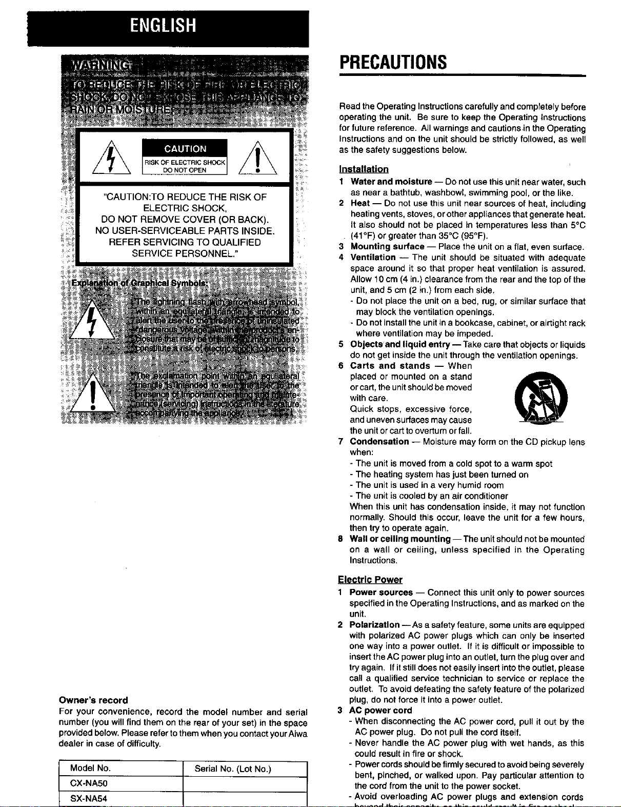
RISK OF ELECTRIC SHOCK
DO NOT OPEN
"CAUTION:TO REDUCE THE RISK OF
ELECTRIC SHOCK,
DO NOT REMOVE COVER (OR BACK).
NO USER-SERVICEABLE PARTS INSIDE.
REFER SERVICING TO QUALIFIED
SERVICE PERSONNEL."
PRECAUTIONS
Read the Operating Instructionscarefullyand completely before
operating the unit. Be sure to keep the Operating Instructions
for future reference. All warnings and cautions inthe Operating
Instructions and on the unit shouldbe strictly followed, as well
as the safety suggestionsbelow.
Installation
1 Water and moisture -- Do not usethis unitnear water, such
as near a bathtub, washbowl,swimming pool, or the like.
2 Heat -- Do not use this unit near sources of heat, including
heatingvents, stoves, or otherappliances thatgenerate heat.
It also should not be placed in temperatures less than 5°C
(41°F) or greater than 35°C (95°F).
3 Mounting surface -- Place the unit on a flat, even surface.
4 Ventilation -- The unit should be situated with adequate
space around it so that proper heat ventilation is assured.
Allow f0 cm (4 in.) ctearanca from the rear and the top ofthe
unit,and 5 cm (2 in.) fromeach side.
- Do not place the unit on a bed, rug, or similar surface that
may blockthe ventilation openings.
- Do not installthe unit ina bookcase, cabinet, or airtightrack
where ventilation may be impeded.
5 Objects and liquid entry -- Takecare thatobjects or liquids
do not get inside the unit through the ventilation openings.
6 Carts and stands -- When
placed or mounted on a stand
or cart, the unit should be moved
with care.
Quick stops, excessive force,
and uneven surfaces may cause
the unit or cart to overturn or fall.
7 Condensation -- Moisture may form on the CD pickup lens
when:
- The unit is moved from a cold spot to a warm spot
- The heating system has just been turned on
- The unit is used in a very humid room
- The unit is cooled by an air conditioner
When this unit has condensation inside, it may not function
normally. Should this occur, leave the unit for a few hours,
then try to operate again.
8 Wall or ceiling mounting-- The unit should not be mounted
on a wall or ceiling, unless specified in the Operating
Instructions.
Owner's record
For your convenience, record the model number and serial
number (you will find them on the retarof your set) in the space
providedbelow.Please refer tothemwhenyou contact yourAiwa
dealer in case ofdifficulty.
Model No.
CX-NA50
L
SX-NA54
Serial No. (Lot No.)
L
Electric Power
1 Power sources -- Connect this unit only to power sources
specified inthe Operating Instructions,andas marked onthe
unit.
2 Polarization -- Asa safety feature, some unitsare equipped
with polarized AC power plugs which can only be inserted
one way into a power outlet. If it is difficult or impossibleto
insertthe AC powerpluginto an outlet,turn the plugover and
try again. If it still does noteasily insert intothe outlet, please
call a qualified service technician to service or replace the
outlet. To avoid defeating the safety feature of the polarized
plug, do not force itinto a power outlet.
3 AC power cord
- When disconnecting the AC power cord, pull it out by the
AC power plug. Do not pullthe cord itself.
- Never handle the AC power plug with wet hands, as this
could resultin fire or shock.
- Power cordsshouldbe firmlysecuredtoavoid beingseverely
bent, pinched, or walked upon. Pay particular attention to
the cord from the unitto the power socket.
- Avoid overloading AC power plugs and extension cords
Page 3
4 Extensioncord-- To help prevent electric shock, do not
use a polarized AC power plug with an extension cord,
receptacle, or other outlet unless the polarized plug can be
completely inserted to prevent exposure of the blades of the
plug.
5 When not in use -- Unplugthe AC power cord from the AC
power plug if the unitwill not be used for several monthsor
more. When the cord isplugged in, a smallamount ofcurrent
continues to flow to the unit, even when the power isturned
off.
TABLEOFCONTENTS
PRECAUTIONS ................................................................... 1
PREPARATIONS
CONNECTIONS ................................................................. 3
REMOTE CONTROL ........................................................... 5
BEFORE OPERATION ........................................................ 5
Outdoor Antenna
Power lines -- When connectingan outdoorantenna, make
sure it is located away from power lines.
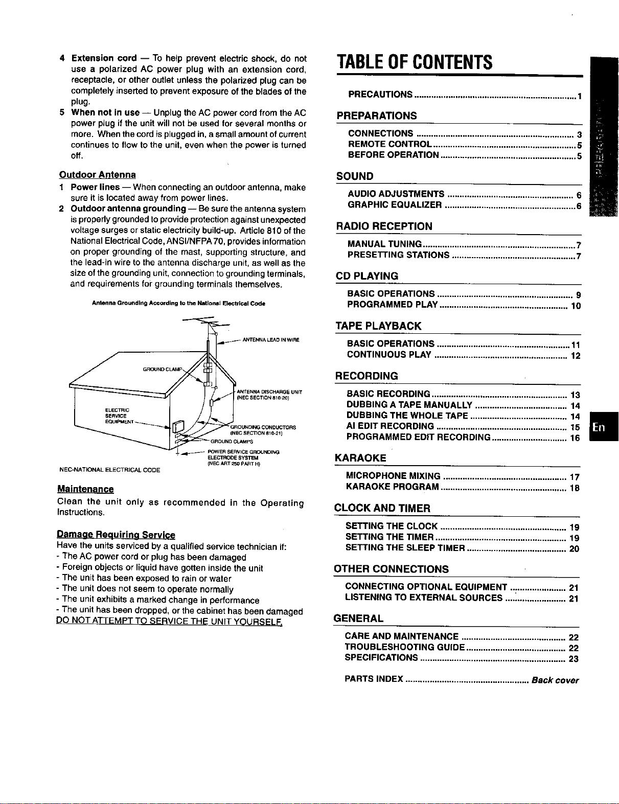
2 Outdoor antenna grounding-- Be sure the antenna system
isproperlygroundedto provide protectionagainstunexpected
voltage surges or staticelectricitybuild-up. Article 810 of the
NationalElectricalCode,ANSI/NFPA 70, providesinformation
on proper grounding of the mast, supporting structure, and
the lead-in wire to the antenna discharge unit, as well as the
size ofthe groundingunit,connectionto grounding terminals,
and requirements fopgroundingterminals themselves.
Antenna Grounding According to the National Electrical Code
GROUND CLAMP_ ANTENNA LEAD IN WIRE
ANTENNA DISCHARGE UNIT
(NEC SECTION 810-20)
ELECTRIC
SERVICE
GROUNOING CONOUCTORS
f _EC SECII(_1810-2_)
CU*I_ps
ELECTRODE SYSTEM
NEC-NATIONAL ELECTRICAL CODE
Clean the unit only as recommended in the Operating
Instructions.
(NEC ART 250 PART H)
D ma uirln rvl
Have the units serviced by a qualifiedservice technician if:
The AC power cord or plug has been damaged
Foreign objects or liquidhave gotten inside the unit
The unit has been exposed to rain or water
The unitdoes notseem to operate normally
The unitexhibits a marked change in pe_ormance
The unit has been dropped, or the cabinet has been damaged
DO NOT ATTEMPT TO SERVICE THE UNIT YOURSELF.
SOUND
AUDIO ADJUSTMENTS .................................................... 6
GRAPHIC EQUALIZER ...................................................... 6
RADIO RECEPTION
MANUAL TUNING ............................................................... 7
PRESE'I-rlNG STATIONS ................................................... 7
CD PLAYING
BASIC OPERATIONS ........................................................ 9
PROGRAMMED PLAY ..................................................... 10
TAPE PLAYBACK
BASIC OPERATIONS ....................................................... 11
CONTINUOUS PLAY ....................................................... 12
RECORDING
BASIC RECORDING ........................................................ 13
DUBBING A TAPE MANUALLY ...................................... 14
DUBBING THE WHOLE TAPE ........................................ 14
AI EDIT RECORDING ...................................................... 15
PROGRAMMED EDIT RECORDING ............................... 16
KARAOKE
MICROPHONE MIXING ................................................... 17
KARAOKE PROGRAM .................................................... 18
CLOCK AND TIMER
SETTING THE CLOCK .................................................... 19
SETTING THE TIMER ...................................................... 19
SETTING THE SLEEP TIMER ......................................... 20
OTHER CONNECTIONS
CONNECTING OPTIONAL EQUIPMENT ....................... 21
LISTENING TO EXTERNAL SOURCES ...._.................... 21
GENERAL
CARE AND MAINTENANCE ........................................... 22
TROUBLESHOOTING GUIDE ......................................... 22
SPECIFICATIONS ............................................................ 23
PARTS INDEX ................................................... Back cover
Page 4
CONNECTIONS
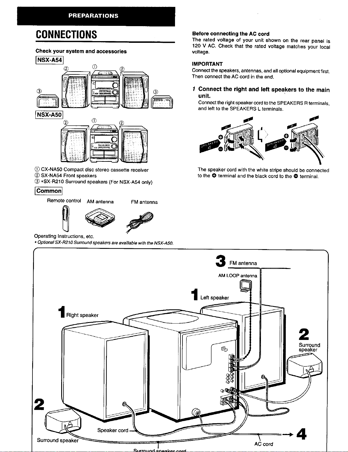
Check your system and accessories
[NSX-AS41
@ @ ®
Before connecting the AC cord
The rated voltage of your unit shown on the rear panel is
120 V AC. Check that the rated voltage matches your local
voltage.
iMPORTANT
Connectthespeakers, antennas, and alloptionalequipmentfirst.
Then connectthe AC cord in the end.
® ®
[.SX-ASO]
® ® ®
(!) CX-NA50 Compact disc stereo cassette receiver
(_ SX-NA54 Front speakers
(_ *SX-R210 Surround speakers (For NSX-A54 only)
[Common]
Remote control
Operating Instructions,etc.
* Optiona/SX-R210Surroundspeakersareavai//ab/ewiththeNSX-A50.
AM antenna FM antenna
1 Connect the right and left speakers to the main
unit,
ConnecttherightspeakercordtotheSPEAKERSRterminals,
andleftto theSPEAKERSLterminals.
The speaker cord withthe white stripe should be connected
to the 0 terminal and the black cord to the • terminal.
12
FM antenna
Left speaker
I Right speaker
2
Surround
speaker
Surround speake_
\
AC cord
Page 5
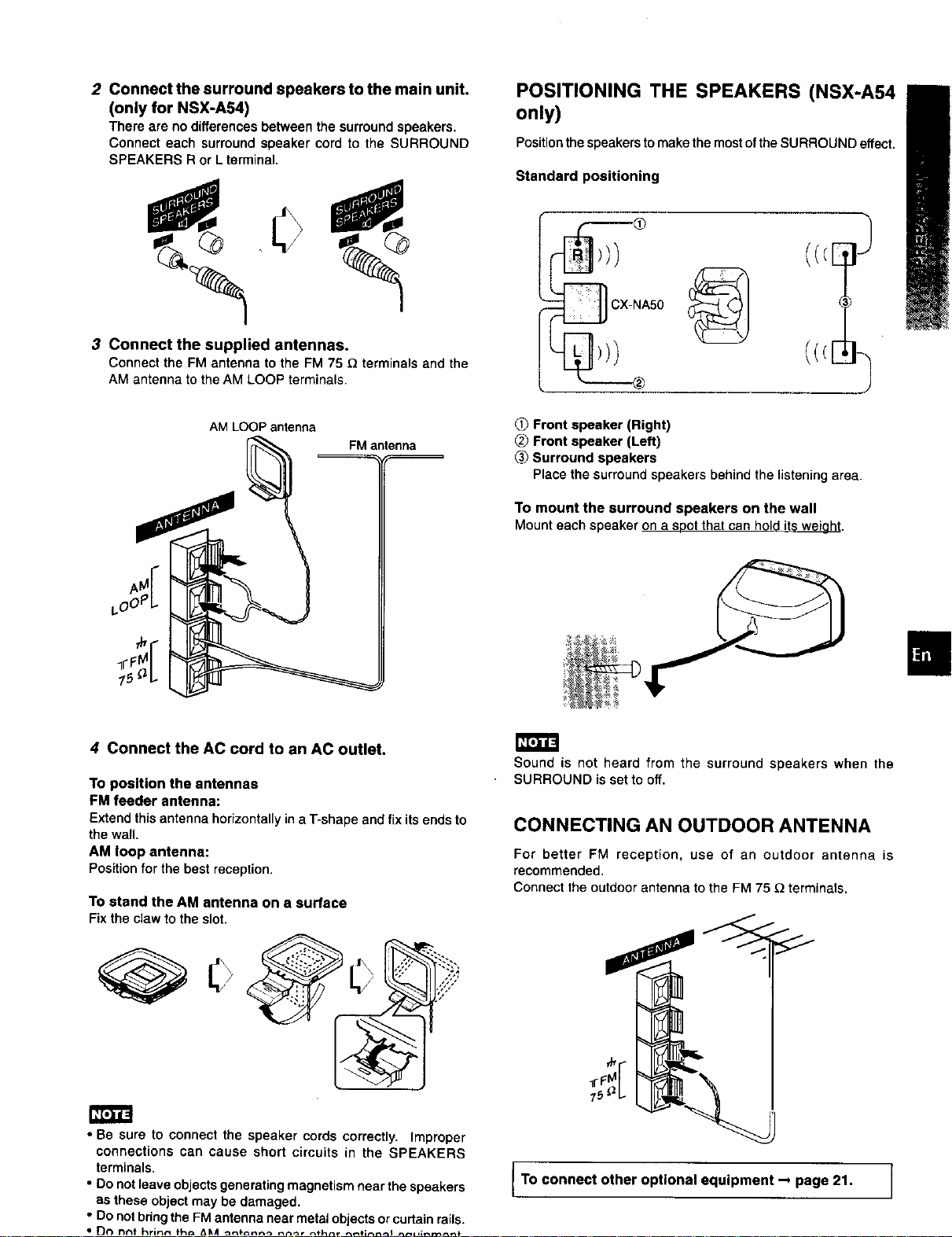
2 Connect the surround speakers to the main unit.
(only for NSX-A54)
There are no differences between the surround speakers,
Connect each surround speaker cord to the SURROUND
SPEAKERS R or L terminal,
POSITIONING THE SPEAKERS (NSX-A54
only)
Positionthespeakers to make the mostofthe SURROUND effect.
Standard positioning
0
3 Connect the supplied antennas.
Connect the FM antenna to the FM 75 _ terminals and the
AM antenna to the AM LOOP terminals.
AM LOOP antenna
FM antenna
}
(((E
_x__
NA50
Front speaker (Right)
Front speaker (Left)
Surround speakers
Place the surround speakers behind the listeningarea.
To mount the surround speakers on the wall
Mount each speaker on a soot thatcan hold its weiaht.
4 Connect the AC cord to an AC outlet.
To position the antennas
FM feeder antenna:
Extend this antenna horizontallyin a T-shape and fix its ends to
the wall,
AM loop antenna:
Positionfor the best reception.
To stand the AM antenna on a surface
Fix the claw to the slot.
• Be sure to connect the speaker cords correctly. Improper
connections can cause short circuits in the SPEAKERS
terminals.
• Do not leave objects generating magnetism near the speakers
as these object may be damaged.
• Do not bring the FM antenna near metal objects orcurtain rails.
Sound is not heard from the surround speakers when the
SURROUND is set to off.
CONNECTING AN OUTDOOR ANTENNA
For better FM reception, use of an outdoor antenna is
recommended.
Connect the outdoor antenna to the FM 75 _ terminals.
75 b
To connect other optional equipment _ page 21. ]
Page 6
REMOTECONTROL BEFOREOPERATION
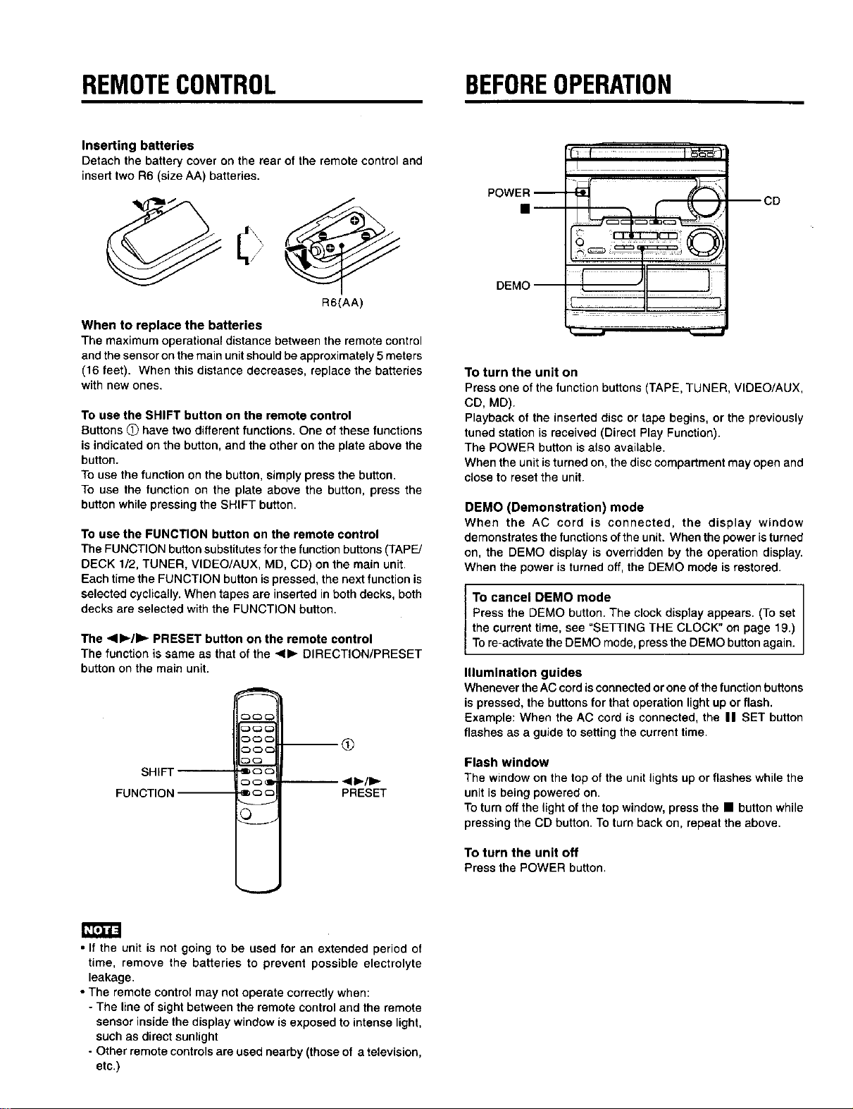
Inserting batteries
Detach the battery cover on the rear of the remote control and
inserttwo R6 (size AA) batteries.
POWER --
CD
R6(AA)
When to replace the batteries
The maximum operational distance between the remote control
and the sensor on the main unit should be approximately5meters
(16 feet). When this distance decreases, replace the batteries
with new ones.
To use the SHIFT button on the remote control
Buttons O have two different functions.One of these functions
is indicated onthe button, and the other on the plate above the
button.
To use the function on the button, simply press the button.
To use the function on the plate above the button, press the
button while pressing the SHIFT button.
To use the FUNCTION button on the remote control
The FUNCTION button substitutesfor the function buttons (TAPE/
DECK 1/2, TUNER, VIDEO/AUX, MD, CD) on the main unit.
Each time the FUNCTION button is pressed, the next function is
selected cyclically.When tapes are inserted in both decks, both
decks are selected with the FUNCTION button.
The <ll_/ll_ PRESET button on the remote control
The function is same as that of the <11_DIRECTION/PRESET
button on the main unit.
_3C3_
_C3_
SHIFT
FUNCTION
'lib 0 C
C3 C3 ql
-- <11_/1_
PRESET
<3
DEMO
AUDIOADJUSTMENTS GRAPHICEQUALIZER
VOLUME
_oae "T-BASS
°°°L
T-BASS
_o_ SHIFT
- VOLUME
_J
GEQ
c_
O
V
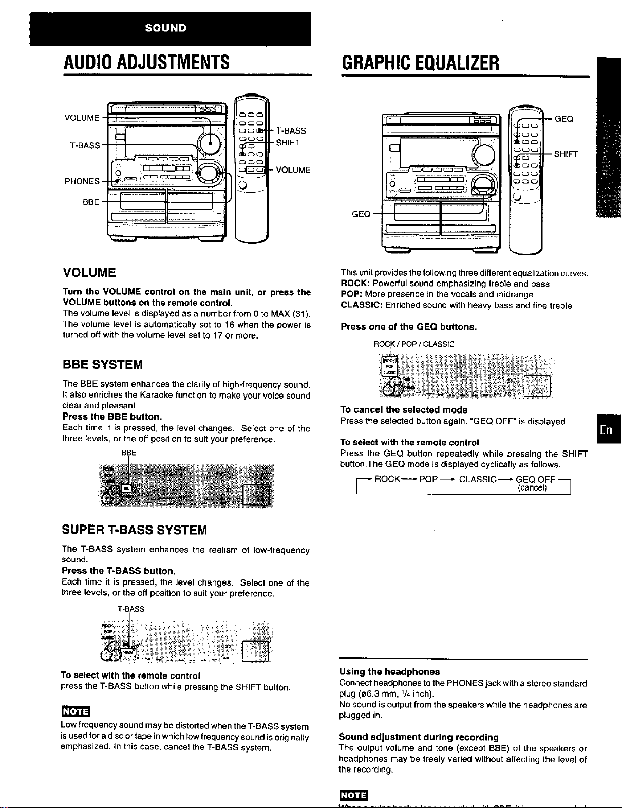
VOLUME
Turn the VOLUME control on the main unit, or press the
VOLUME buttons on the remote control.
The volume level is displayed as a number from 0 to MAX (31).
The volume level is automatically set to 16 when the power is
turned off with the volume level set to 17 or more.
BBE SYSTEM
The BBE system enhances the clarity of high-frequency sound.
It also enriches the Karaoke function to make your voice sound
clear and pleasant.
Press the BBE button.
Each time it is pressed, the level changes. Select one of the
three levels, or the off position to suit your preference.
BSE
SUPER T-BASS SYSTEM
The T-BASS system enhances the realism of low-frequency
sound.
Press the T-BASS button.
Each time it is pressed, the level changes. Select one of the
three levels, or the off positionto suit your preference.
T-BASS
This unit provides thefollowing threedifferent equalization curves.
ROCK: Powerful sound emphasizing treble and bass
POP: More presence in the vocals and midrange
CLASSIC: Enriched sound with heavy bass and fine treble
Press one of the GEQ buttons.
ROCK/ POP/ CLASSIC
To cancel the selected mode
Press the selected button again. "GEQ OFF" is displayed,
To select with the remote control
Press the GEQ button repeatedly while pressing the SHIFT
button.The GEQ mode is displayed cyclically as follows.
_" ROCK "-'_ POP-_," CLASSIC-._- GEQ OFF
(cancel) J
To select with the remote control
press the T-BASS button while pressing the SHIFT button.
Low frequency sound may be distorted when the T-BASS system
isused for a disc ortape in which low frequency sound is originally
emphasized. In this case, cancel the T-BASS system.
Using the headphones
Connect headphones to the PHONES jack with a stereo standard
plug (e6.3 mm, V4inch).
No soundis output from the speakers while the headphones are
plugged in.
Sound adjustment during recording
The output volume and tone (except BBE) of the speakers or
headphones may be freely varied without affecting the level of
the recording,
J J
Page 8
MANUALTUNING PRESETTINGSTATIONS
2
1-
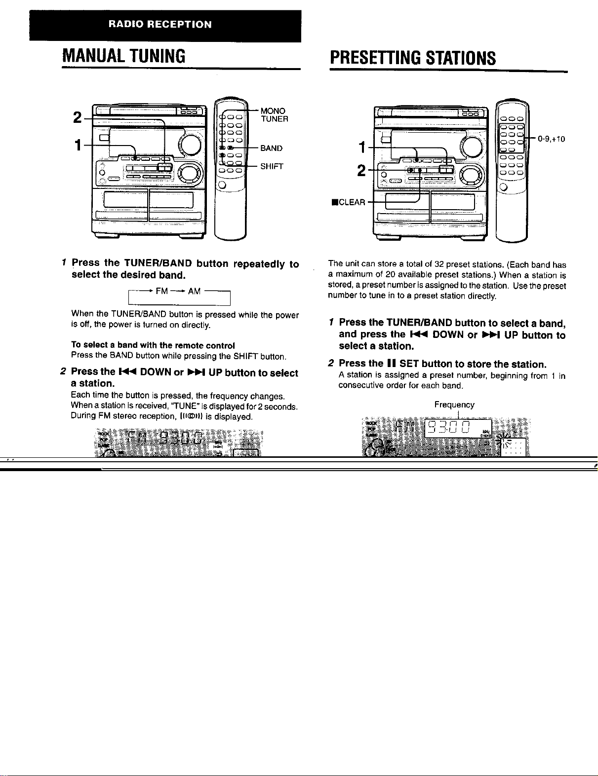
1 Press the TUNER/BAND button repeatedly to
select the desired band.
I_FM _ AM
When the TUNER/BAND button is pressed while the power
is off, the power is turned on directly.
To select a band with the remote control
Press the BAND button while pressing the SHIFT button.
2 Press the _ DOWN or I_N UP button to select
a station.
Each time the button is pressed, the frequency changes.
When a stationisreceived,=TUNE"isdisplayedfor 2seconds.
During FM stereo reception, (l(_)| is displayed.
I ......
- 0-9,+10
_C3_
The unit can store a total of 32 preset stations. (Each band has
a maximum of 20 available preset stations.) When a station is
stored, apreset number is assigned to the station. Usethe preset
number to tune in to a preset station directly.
1 Press the TUNER/BAND button to select a band,
and press the _ DOWN or _ UP button to
select a station,
2 Press the II SET button to store the station.
A station is assigned a preset number, beginning from I in
consecutive order for each band.
Frequency
Page 9

PRESET NUMBER TUNING
Usethe remotecontroltoselectthepresetnumberdirectly,
1 Press the BAND button while pressing the SHIFT
button to select a band.
2 Press the numbered buttons to select a preset
number.
Example:
To setectpreset number20, press the +tO,+10and 0 buttons.
Toselect preset number 15, press the +10 and 5 buttons.
Selecting a preset number on the main unit
Press the TUNER/BAND button to select a band. Then, press
the 41b DIRECTION/PRESET button repeatedly.
Each time the buttonis pressed, the next ascending number is
selected.
To clear a preset station
Select the presetnumber of thestation tobe cleared. Then, press
the • CLEAR button, and press the II SET button within 4
seconds.
The preset numbers ofall other stationsin the band with higher
numbers are also decreased by one.
To change the AM tuning interval
The default setting of the AM tuning interval is 10 kHz/step. If
youusethisunitinan area where thefrequency allocationsystem
is9 kHz/step, change the tuning interval.
Press the POWER button while pressing the TUNER/BAND
button.
To reset the interval, repeat thisprocedure.
When the AM tuning interval ischanged, all preset stations (see
Page 10

BASICOPERATIONS
--AOPEN/CLOSE-_._
DISC_
DISC I I I_'t
DIREC3" ........
CD
PLAY
II
N
REPEAT
3'_c " 0-9,+10
3C.3
:_oc - SHIFT
L
To play one disc only, press one of the DISC DIRECT
PLAY buttons.
The selecteddiscisplayedonce,
To stop play, press the • button.
To pause play, press the I I button. Toresume play,pressagain.
To search for a particular point during playback, keep the
<1<1or _ button pressed and release the buttonatthe desired
point.
To skip to the beginning of a track during playback, press
the <t<1 or _ button repeatedly.
To remove discs, press the --_OPEN/CLOSE button.
To start play when the power is off (Direct Play Function)
Press the CD button. The power is turned on and play of the
loaded disc(s) begins.
When the _AOPEN/CLOSE button is pressed, the power is also
turned on.
CD EDIT/
CHECK _ • ;
LOADING DISCS
Press the CD button, then press the • OPEN/
CLOSE button to open the disc compartment. Load
disc(s) with the label side up.
To play one or two discs, place the discs on tray 1 end 2.
To pray three discs, press the DISC CHANGE button to rotate
the trays after placing two discs. Place the third disc on tray 3.
Close the disc compartment by pressing the '_ OPEN/CLOSE
button.
F------ DISC CHANGE
Tray 1
Tray number of the
disc to be played Total playing time
Total number of tracks
To check the remaining time
During play,press the CD EDIT CHECK buttononthe main unit
orthe EDIT/CHECK button onthe remote controlwhile pressing
the SHIFT button. The amount oftime remaining untilall tracks
finish playing is displayed. To restore the playing time display,
repeat the above.
Selecting e track with the remote control
1 Press one of the DfSC DIRECT PLAY buttons to select a disc.
2 Press the numbered buttons and the +10 button to select a
track.
Example:
To select the 25th track, press the +10, +10 and 5 buttons.
Toselect the 10th track, press the +10 and 0 buttons.
The setected track starts to p{ayand continues to the end of
that disc.
Replacing discs during play
While one discis playing,the other discscan be replacedwithout
interrupting play.
1 Press the DISC CHANGE button.
2 Remove the discs and replace with other discs.
3 Press the A OPEN/CLOSE button to close the disc
compartment.
1_,3u_.
• When loading an 8-cm (3-inch) disc, put it onto the inner circle
of the tray.
• Do not place more than one compact disc on one disctray.
• Do not tilt the unit with discs loaded. Doing so may cause
malfunctions.
PLAYING DISCS
Load discs.
To play all discs inthe disc compartment, press the
<11_ button.
Playbegins withthedisc ontray1.
Elapsed playing time
Number of track
being played
Page 11

RANDOM/REPEAT PLAY
Use the remote control.
RANDOM play
All the tracks on the selected disc or on all the discs can be
played randomly.
A single disc or all the discs can be played repeatedly. _
Press the RANDOM/REPEAT button while pressing the _ i
SHIFT button.
Each time it is pressed, the function can be selected cyclically. Selected track number Totalnumber of
RANDOM play -- RANDOM lights up on the display, selected tracks
REPEAT play -- _ lights up on the display.
RANDOM/REPEAT play -- RANDOM and _ light up on 4 Repeat steps 2 and 3 to program other tracks.
the display,
Cancel -- RANDOM and _ go out from the display. 5 Press the < I_ button to start play.
3 Press the numbered buttons and the +10 button
to program a track.
Example:
Toselectthe25thtrack,pressthe+10, +10and5 buttons.
Toselectthe 10thtrack,pressthe+10 and0 buttons.
Total playing time of
Program number
the selected tracks
)
'l_[o]lJI=
During random play following operations are not possible:
-to select the tracks directly with the numbered buttons.
-to skip to the previously played track with the <1<1button.
PROGRAMMEDPLAY
Up to 30 tracks can be programmed from any of the inserted
discs.
2
5
O
To check the program
Each time the <1<1or I_ button is pressed in stop mode, a
disc number, track number, and program number will be
displayed.
To clear the program
Press the • CLEAR button in stop mode.
To add tracks to the program
Repeat steps2 and 3in stop mode,The track willbe programmed
after the last track.
To change the programmed tracks
Clear the program and repeat all the steps again.
During programmedplay, you cannot performrandomplay,check
the remaining time, and select a disc or track.
Usethe remotecontrol.
1 Press the PRGM button twice while pressing the
SHIFT button in stop mode.
The PRGMindicatorlightsuponthedisplay,
• When the PRGM button is pressed once in step 1, the unit
enters the KARAOKE PROGRAM (page 18).
2 Press one of the DISC DIRECT PLAY buttons to
select a disc.
The selected disc is indicated in red on the display.
Go to the next step when the tray stops rotating,
Page 12

BASICOPERATIONS
When tapes are loaded In both decks
Press the TAPE button firstto select a deck.
The selected deck number isdisplayed.
To stop play, press the • button.
To pause play (deck 2 only), press the II button. To resume
play, press again.
To change the playback side, press the <i_ DIRECTION/
PRESET button in play or pause mode.
To fast forward or rewind, press the <1<1or _ button. Then
press the • button to stop the tape.
REV MODE
_AEJECT --
Deck1
• On deck 1, tapes are always played back on both sides,
On deck 2, you can select a reverse mode to play back one or
both sides.
• Use Type ] (normal), Type l[ (high/Cr02) or Type IV (metal)
tapes for playback.
1 Press the TAPE button and press the _A EJECT
mark to open the cassette holder.
Insert a tape with the exposed side down. Push the cassette
holder to close.
To start play when the power is off (Direct Play Function)
Press the TAPE button The power isturned on and play of the
inserted tape begins.
To set the tape counter to O000
Press the • CLEAR button in stop mode.
The counter is also set to 0000 when the cassette holder is
opened.
MUSIC SENSOR
If there is a 4-second or longer blank between each track, a
search for the beginning of the current or next track during
playback can be done easily.
Press the _ or _ button during playback referring to the
playback side indicator (4 or I=.-)on the display.
For example, when the I_ button is pressed while I_ is
displayed, playback of the next track starts.
Music sensor function may not be able to detect tracks under
the following conditions:
• Blanks of less than 4 seconds between tracks
• Noisy blanks
• Long passages of low-end sound
• Low overall recording levels
2 Press the <11_ button to start play.
The tape counter indicates
the tape runninglength.
tt t ; _t J
i_..t L!
Playback side indicator
I_: The front side is being played (forward).
4: The back side is being played (reverse).
To select a reverse mode (deck 2 only)
Each time the REV MODE buttonis pressed, the reverse mode
changes.
,J € Wh'L'UI
%!
To play one side only, select .C.
To play from front side to reverse side once only, select _'T).
TOplay both sides repeatedly, select (C).
• When tapes are loaded in both decks, C) on the display
indicates Continuous Play
Page 13

CONTINUOUSPLAY
f About cassette tapes
• To prevent accidental erasure, break off the plastic tabs
on the cassette tape after recordingwith a screwdriver or
other pointedtool.
i
__
__
-'1 1
After playback on one deck finishes, the tape in the other deck
will start to play without interruption.
4
1 Insert tapes into deck 1 and deck 2.
2 Press the TAPE/DECK1/2 button to select the
deck to be played back first.
3 Press the REV MODE button to select _:).
4 Press the <11_ button to start playback,
Playbackcontinuesuntilthe • buttonis pressed.
__[-- TabforsideA
I detection ../_'_,,,,i
Is tot J
To record on the tape again, cover the tab openings with
adhesive tape, etc. (On Type [t tapes, take care not to
cover the Type [[ tape detection slot.)
• 120-minute or longer tapes are extremely thin and easily
deformed or damaged. They are not recommended.
• Take up any alack in the tape with a pencil or similar tool
before use. Slack tape may break or jam in the mechanism.
Page 14

BASICRECORDING
This section explains how to record from the tuner, CD player, or
external equipment.
To stop recording, press the • button.
To pause recording, press the I I button. (Applicable when the
source isTUNER, VIDEO/AUX or MD.) To resume recording,
press again.
INSERTING BLANK SPACES
(, t I °o'-'-_I
i
3
_c:31
_>, _ iii: iiii iii. i _ ii "i .... ,_
4
.i:,::- I|-t :-)i
......... J
Preparation
• Set the tape to the pointwhere recording will start.
• Use Type ] (normal) and Type 11(high/Cr02) tapes for recording.
1 Insert the tape to be recorded on into deck 2.
Insert the tape with the side to be recorded on first facing
out from the unit,
1
2
Insertion of 4-second blank spaces enables you to activate the
Music Sensor function. (Applicable when the source is TUNER,
VlDEO/AUX or MD.)
1 Press the • REC/REC MUTE button during recording or
while in recording pause mode,
on the display flashes for 4 seconds and the tape runs
without recording. After 4 seconds, the deck enters the
recording pause mode.
2 Pressthe II button to resume recording.
To insert a blank space of less than 4 seconds, pressthe •
REC/REC MUTE button again while _ isflashing.
To Insert blank spaces of more than 4 seconds, after the
deck enters recording pause mode, press the • REC/REC MUTE
button again. Each time the button is pressed, a 4-second blank
space is added.
2 Press the REV MODE button to select the reverse
mode.
To recordon one sideonly,select =.
Torecordon both sides,select =) or (=).
3 Press one of the function buttons and prepare
the source to be recorded.
To record from a CD, press the CD button and load the
disc(s).
TOrecord from a radio broadcast, press the TUNER button
and tune in to a station.
To record from a connected source, press the VlDEO/AUX
or MD button and play.
4 Press the • REC/REC MUTE button to start
recording.
When the selected function is CD, playback and recording
start simultaneously.
To erase a recording
Make sure the microphoneis not connected to this unit.
1 Insert the tape to be erased intodeck 2 and press the TAPE/
DECK 1/2 buttonto display"TP 2".
2 Set the tape to the pointwhere the erasure is to be started.
3 Set the reverse mode by pressing the REV MODE button.
Page 15

DUBBINGATAPEMANUALLY DUBBINGTHEWHOLETAPE
1_3--
R2
This function allows you to make exact copies of both sides of
the original tape. The reverse side of both tapes will start
• Set the tape to the point where recording will start.
• The reverse mode is automatically set to _..
Note that recording will be done on one side of the tape only.
1 Press the TAPE button.
simultaneously as soon as the longer tape has been reversed.
• Dubbing does not startfrom a point halfway in the tape,
• The reverse mode is automatically set to .T.).
2 Insert the original tape into deck 1 and the tape
to be recorded on into deck 2,
Insertthetapeswiththesidesto beplayedbackorrecorded
on facingoutfromtheunit,
3 Press the TAPE/DECK 1/2 button to select
deck 1.
"TP 1"isdisplayed,
4 Press the • REC/REC MUTE button to start
recording.
PJayingandrecordingstartsimultaneously,
To stop dubbing
Pressthe • button,
1
Press the TAPE button.
2
Insert the original tape into deck 1 and the tape
to be recorded on into deck 2.
Inserteachtapewiththe sidetobe playedbackorrecorded
on firstfacing outfrom the unit.
3
Press the SYNCHRO DUBBING button once or
twice to start recording,
For recording at normal speed, press it once to display
NORM-DUB.
For recording at high speed, press it twice to display
HIGH-DUB.
The tapes are rewound to the beginning of the front sides,
and recording starts.
To stop dubbing
Pressthe • button.
Recordingdoes not start, if the erasure prevention tab on either
side of the tape is broken off.
=1
Page 16

AIEDITRECORDING
4
s .....
C3_
_ -- 0-9,+10
_QC
6 Press the • REC/REC MUTE button to start
recording.
The tape is rewound to the beginning of the front side, the
lead segment is playedthroughfor 10seconds, and recording
starts. When recordingon the front (side A) ends, recording
on the back (side B) starts.
To stop recording
Press the • button.Recordingand CD playstopsimultaneously.
To clear the edit program
Press the • CLEAR buttontwice so that "EDIT" disappears on
the display.
= : .:: =
The AI edit function enables CD recordingwithoutworryingabout
tape length and track length. When a CD is inserted, the unit
automatically calculates the total track length. Ifnecessary, the
order of tracks is rearranged so that no track is cut short.
(AI: Artificial Intelligence)
AI edit recording willnot start from a point halfway into the tape.
The tape must be recorded from the beginning of either side.
1 Insert the tape into deck 2.
Insert the tape with the side to be recorded onfirst _ec{ngout
from the unit.
2 Press the CD button and load the disc(s).
3 Press the CD EDIT/CHECK button once,
"EDIT"and "AI" lightsup on thedisplay.
AI EDIT
Each time it is pressed, the display changes as follows.
_ A] EDIT _ PRGM EDIT - I
To select with the remote control, press the EDIT/CHECK
button while pressing the SHIFT button.
4 Press one of the DISC DIRECT PLAY buttons to
select a disc,
5 Press the <i<1 or _ button to designate the
tape length.
10 to 99 minutes can be specified.
Ina few seconds, the microcomputer determines the tracks
to be recorded on each side of the tape.
• The numbered buttons on the remote control are also
available to designate the '_.pe length.
Example: When using a 60-minute tape, press the 6 and 0
buttons.
Tape side A Selected
Tape length (front side) tracksfor side A
To check the order of the programmed track numbers
Before recording,press the CD EDIT/CH ECK to select side A or
B, and press the <t<1 or _ button repeatedly,
Programmed
Track number track numbers
Program number
To add tracks from other discs to the edit program
If there is any time remaining on the tape after step 5, you can
add tracks from other discs in the CD compartment.
1 Press the CD EDIT/CHECK button to select side A or B.
2 Press one of the DISC DIRECT PLAY buttons to select a disc.
3 Press the numbered buttons on the remote control to select
tracks. "PRGM" appears on the display.
A track whose playing time islonger than the remaining time
cannot be programmed.
4 Repeat steps 2 and 3 to add more tracks.
Time on cassette tapes and editing time
The actual c_ssette recording time is usually a little longer than
the specified recording time printed on the label. This unit can
program tracks to use the extra time. When the total recording
time is a little longer than the tape's specified recording time
after editing, the display shows the extra time (without a minus
mark), instead of the time remaining on the tape (with the minus
mark).
• Recording is inhibited if the erasure prevention tab on either
side of the tape is broken off.
• The AI edit function cannot be used with discs containing 31
tracks or more.
Remaining time of side A
Page 17

PROGRAMMEDEDITRECORDING
4
2
i !i o= _0
I-
8-
6 Repeat step 5 for the rest of the tracks for side A.
A track whose playingtime is longer than the remainingtime
cannot be programmed.
Remainingtime
ofside A
Total number Programmed
of pmgrammed tracks
tracks
377 -
1
Programmed edit functionenables CD recording while checking
the remaining time on each side of the tape as the tracks are
programmed,
The programmed edit recordingwillnotstartfrom a point halfway
in the tape. The tape must be recorded from the beginning of
either side.
1 Insert the tape into deck 2.
Insert the tape with the side to be recorded on first facing out
from the unit.
2 Press the CD button and load the disc(s).
3 Press the CD EDIT/CHECK button twice.
"EDIT" and "PRGM"lightsupon the display.
PRGM EDIT
7 Press the CD EDIT/CHECK button to select side
B and program the tracks for side B.
After confirmingBon the display,repeatstep 5.
Tapeside B (reverseside)
8 Press the • REC/REC MUTE button to start
recording.
The tapeis rewoundto the beginningofthe frontside, the
leadsegmentisplayedthroughfor 10seconds,andrecording
starts.Whenrecordingonthefront side(A) ends,recording
onthebackside(B)starts.
To stop recording
Pressthe • button,RecordingandCD play stop simultaneously.
To check the order of the programmed track numbers
Before recording, press the CD EDIT/CHECK button to select
side A or B, and press the _ or I_b button repeatedly.
Program number
To select with the remote control, press the EDIT/CHECK
button while pressing the SHIFT button.
4 Press the <1<1 or _ button to designate the
tape length.
10 to 99 minutes can be specified.
Maximum recording
Tape length time for side A
Tape side A (front side)
5 Press the one of the DISC DIRECT PLAY buttons
to select a disc.
Then, press the numbered buttons and the + 10
button on the remote control to program a track.
Example: TOselectthe 10thtrackofdisc2, presstheDISC
DIRECTPLAY2 button,thenpress the+ 10 and 0 buttons.
Track number Programmed
To change the program of each side
Press the CD EDIT/CHECK button to select side A or B, and
press the • CLEAR buttonto clear the program of the selected
side. Then program tracks again.
To clear the edit program
Pressthe • button twice so that"EDIT' disappears onthedisplay
Recordingisinhibited ifthe erasure prevention tab on either side
of the tape is broken off.
track numbers
Page 18

MICROPHONEMIXING VOCAL FADER/MULTIPLEX FUNCTIONS
This unit can use discs or tapes as Karaoke sources.
Press the KARAOKE button repeatedly to select the vocal
fader or multiplex function.
2
4
KARAOKE-
A microphone (not supplied) can be connected to this unit,
allowing you to sing along to music sources.
Use a microphone with mini plugs (e3.5 mm, V8 inch).
1 Connect your microphone to the MIC jack,
MIC
Use the vocal fader function for ordinary discs or tapes.
Use the multiplex functionfor multi audio discs or tapes.
Each time the KARAOKE button is pressed, one of these
functionsis selected cyclically,
@ ® ®
_/ !_ii¸ _'7 _'- !_
(_ Vocal Fader
The singer's voice becomes softer than the accompaniment.
_) Auto Vocal Fader
The singer's voice becomes softer only while there is audio
inputthrough a microphone.
(_ Multiplex
Only the sound on the left channel is heard from both
speakers, and the sound on the right channel is muted.
2 Press one of the function buttons to select the
source to be mixed, and play the source.
3 Adjust the volume and tone of the source.
4 Turn the MIC VOL control to adjust the
microphone volume.
To record microphone sound mixed with source sound
Follow the procedure for recording from the sound source (see
page 13),
The SYNCHRO DUBBING button cannot be used for mixing
recording.
When not using the microphone
Set the microphone volume to MIN and remove the microphone
from the MIC jack.
'lL[_,]ul=
• If a microphone is held too near the speakers, a howling sound
may be produced. In this case, hold the microphone away
from the speakers, or decrease the microphone volume.
• If sound through the microphone is extremely loud, it may be
distorted. In this case, decrease the microphone volume.
Recommended microphones
The use of unidirectional type microphone is recommended to
prevent howling. Contact your local Aiwa dealer for details,
(_ Auto Multiplex
The sound on the left channel is heard from both speakers,
and the sound on the right channel is muted only while there
is audio input through a microphone.
_Cancel
To change the time lag setting in Auto Vocal Fader or
Auto Multiplex function
The muted original singer's voice can be turned faster to the
normal level.
When Auto Vocal Fader or Auto Multiplex is selected, "A-VF" or
"AUTO MPX" is displayed for 3 seconds and changes to the
selected function name. After the selected function name is
displayed, hold down the KARAOKE button until FAST is
displayed.
To return to the initial setting, select SLOW.
When the power is turned off, SLOW is restored.
To change the audible channel in Multiplex function
Only the sound on the right channel can be heard from both
speakers.
When Multiplex isselected,"MPX Loch"isdisplayedfor3seconds
and changes to the selected function name. After the selected
functionname isdisplayed, holddown the KARAOKE button until
MPX-R is displayed.
To return to the initial setting, select MPX-L.
When the power is turned off, MPX-L is restored.
• The Karaoke functions may not operate correctly with the
following kinds of CDs or tapes.
- Those with monaural sound
- Those recorded with strong echoes
* Those with the vocal part recorded on the right or left side of
the sound width
• While the Karaoke function is on, the sound is output as
monaural.
Page 19

KARAOKEPROGRAM
i
1
1
4
Before or during CD play, you can reserve up to 15 tracks to be
played after the current track. Each reservation is cleared when
it finishes playing,
Usethe remotecontrol.
1 Press the PRGM button while pressing a SHIFT
button once.
2 Press one of the DISC DIRECT PLAY buttons to
select a disc.
Then, press the numbered buttons and the + 10
button to program a track.
To add a reservation during play
Repeat step 2.
To check the reserved tracks
Press the CD EDIT/CHECK button on the main unit or the EDIT
CHECK buttonwhile pressing the SHIFT button on the remote
controlrepeatedly. Each time it is pressed, the discnumber and
track number are displayed in the reserved order,
To stop play
Press the • button. When the <11_button is pressed, the play
starts from the last track again.
To skip a current track
Press the _ button. The skipped track is cleared from the
program,
To clear all the reservations
Press the _ button repeatedly until"K - PO0" is displayed.
-- m
Press it once more to cancel the Karaoke programs. The display
returns to that of CD play.
[2[.]=1-"
• If the reserved track number does not exist on the selected
disc, the unit stops playing and the display flashes.
In this case, press the _ button to skip the error track. Then
press the <11_button to start play with the next reserved track.
• When the PRGM button is pressed repeatedly in step 1, PRGM
is displayed and the unit enters CD program play mode (page
fO).
To cancel program play, press the • CLEAR button.
Reserved disc number Reserved track number
3 Repeat step 2 to reserve other tracks.
4 Press the <11_ button to start play.
After a trackisplayed,itis clearedfromtheprogram.
Disc number of the Number of remaining
last reservation reserved tracks
Currently Track number of Currently playing
playing disc the last reservation track number
flashes
Page 20

SETTINGTHECLOCK SE'FrlNGTHETIMER
-1
2,31,2,3-
=
1 Press the CLOCK button while pressing the
SHIFT button on the remote control, and press
the II SET button within 4 seconds.
2 Press the <1<1 DOWN or _ UP button to
designate the hour, and press the I I SET button.
The hour stops flashing and the minute starts flashing.
3 Press the _ DOWN or _ UP button to
designate the minute, and press the II SET
button.
The minute stops flashing on the displayand the clock starts
from 00 seconds,
To display the current time
Press the CLOCK button while pressing the SHIFT button on
the remote control. The time isdisplayed for 4 seconds.
However, the time cannot be displayed during recording.
1"oswitch to the 24-hour standard
Press the CLOCK button while pressing the SHIFT button on
the remote control and then press the • button within 4 seconds.
Repeat the same procedure to restore the 12-hour standard.
1,2 -+°°
2,4
6
The unit can be turned on at a specified time every day with the
built-in timer.
Preparation
Make sure the clock is set correctly.
Usethe remotecontrol.
1 Press the TIMER button while pressing the SHIFT
button once to display _), and press the II SET
button within 4 seconds.
_) isdisplayed,andthe hourflashes,
'l£[,]lJl:--
If you press the II SET button after 4 seconds, another
operation may start.
2 Designate the hour of the timer-on time by
pressing the _ DOWN or _ UP button, and
press the I I SET button. Repeat to designate the
minute of the timer-on time.
If the clock display flashes
This is caused by a power interruption. The current time needs
to be reset.
Ifpower is interrupted for more than approximately 24 hours,
all settings stored in memory after purchase need tobe reset.
After you designate the timer-on time, one of the source name
flashes on the display for 4 seconds.
Within 4 seconds, press the FUNCTION button
repeatedly to select a source•
The selectedsource name flashesfor4 seconds, Atthistime,
the selected function button does not lightup.
• If this step is not completed within 4 seconds, repeat from
step 1.
• If the TUNER is selected, the band cannot be selected in
this step.
Page 21

4 Within 4 seconds, select the duration for the
timer-activated period with the I<1< DOWN or
UP button,
SETTINGTHESLEEPTIMER
The duration for the timer-activated period can be set between
5 and 240 minutes in 5-minute steps.
• If this step is not completed within 4 seconds, repeat from
step 1.
5 Prepare the source.
To listen to a CD, load the disc to be played first ontray 1.
To listen to a tape, insert the tape intodeck 1 or 2.
To listen to the radio, tune in to a station.
6 Press the POWER button to turn the unit off after
adjusting the volume and tone,
(_ remainson the displayafter thepower isturnedoff(timer
standby mode).
When the timer-on time is reached, the unit turns on and
begins play with the selected source.
• The volume level is automatically set to 16 when the power
is turned off with the volume level set to 17 or more.
To check the specified time and source
Press the TIMER button while pressing the SHIFT button. The
timer-on time, the selected source name and the duration for
the timer-activated period are displayed for 4 seconds.
1
2
o.R_
The unit can be turned off automatically at a specified time.
Use the remote control.
1 Press the SLEEP button while pressing the SHIFT
button.
2 Within 4 seconds, press the _ or _ button
to specify the time until the power is turned off.
Each time the buttonispressed, the time changes between 5
and 240 minutes in 5-minute steps.
Specified time
II
To cancel timer standby mode temporarily
Press the TIMER button repeatedly while pressing the SHIFT
buttonrepeatedly so that _) or_)REC disappears onthe display.
To restore the timer standby mode, pressagain to display _) or
_)REC.
Using the unit while the timer is set
You can use the unit normally after setting the timer.
Before turningoffthe power,repeat step 5 to prepare the source,
and adjustthe volume and tone.
_,]ut=
• Timer playback and timer recording will not begin unless the
power isturned off.
• Connected equipment cannot be turned on and off by the built-
in timer of this unit. Use an external timer.
TIMER RECORDING
Timer recording isapplicable for TUNER and VIDEO/AUX (with
an external timer) sources only.
Press the TIMER button _ while pressing the SHIFT
button so that _)REC appears on the display, end press the
II SET button within 4 seconds. Repeat the steps shown
above from step 2 and insertthe tape to be recorded into deck 2
after step 5.
To check the time remaining until the power is turned off
Press the SLEEP button once while pressingthe SHIFT button.
The remaining time isdisplayed for 4 seconds.
To cancel the sleep timer
Press the SLEEP button twice while pressing the SHIFT button
so that "SLEEP" on the display disappears,
Page 22

CONNECTINGOPTIONAL
LISTENINGTOEXTERNAL
EQUIPMENT
f--'--_j._ -- CD DIGITAL OUT
_ -- VIDEO/AUX
• -- MD
i__,_I. SPEAKERS
Refer to the operating instructions of the connected equipment
for details.
• The connecting cords are not supplied. Obtain the necessary
connecting cords.
• Consult your local Aiwa dealer for optional equipment.
VIDEO/AUX, MD JACKS
This unit can input analog sound signals through these jacks.
Use a cable with RCA phono plugs to connect audio equipment
(turntables, LD players, MD players, VCRs, TV, etc.).
Connect the red plug to the R jack, and the white plug to the L
jack.
When connecting a turntable
Use an Aiwa turntable equippedwith abuilt-in equalizer amplifier.
LINE OUT JACKS
This unit can output analog sound signal through these jacks.
Use a cable with RCA phono plugs to connect audio equipment
with LINE IN (analog input) jacks.
Do not connect an equipment to the LINE OUT terminals and
VIDEO/AUX terminals simultaneously. Otherwise, noise is
generated and malfunction occurs.
CD DIGITAL OUT (OPTICAL) JACK
This unitcan output CD digitalsound signalsthrough this jack.
Use an optical cable to connect digital audio equipment (digital
amplifier,DAT deck, MD recorder, etc.).
Remove the dust cap _ from the CD DIGITAL OUT (OPTICAL)
jack. Then, connect an optical cable plug to the CD DIGITAL
OUT (OPTICAL) jack.
(OPTICAL)
-- LINE OUT
--SURROUND
SUPER
Ul WOOFER
SOURCES
POWER
To play equipment connected to the VIDEO/AUX jacks or MD
jacks, proceed as follows.
1 Press the VIDEO/AUX or MD button.
When a equipment connected to the VIDEO/AUX jacks is
played: press the VIDEO/AUX button.
When a equipment connected to the MD jacks is played:
press the MD button.
2 Play the connected equipment.
To change a source name in the display
When the VIDEO/AUX button is pressed, VIDEO is displayed
initially. It can be changed to AUX or TV.
With the power on, press the POWER button while pressing the
VIDEO/AUX button.
Repeat the procedure to select one of the names.
To adjust the sound level of the external source
When the sound level of the external source is much higher or
much lower than that of other function sources, adjust it as
follows.
1 Press the VIDEO/AUX or MD button and play the equipment.
2 Presss the <1.< or IH_ button so that the sound level
becomes the same as that of other function sources.
During recording, the sound level can not be adjusted.
When the CD DIGITAL OUT (OPTICAL) jack is not being
used
Attach the supplied dust cap.
SUPER WOOFER <] JACK
Page 23

CAREANDMAINTENANCE TROUBLESHOOTINGGUIDE
Occasional care and maintenance of the unit and the software
are needed to optimize the performance of your unit.
To clean the cabinet
Use a soft and dry cloth.
If the surfaces are extremely dirty, use a soft cloth lightly
moistened with mild detergent solution. Do not use strong
solvents, such as alcohol, benzine or thinner as these could
damage the finishof the unit.
To clean the heads and tape paths
After every 10 hours of use, clean the heads and tape paths
with a head cleaning cassette or cotton swab moistened with
cleaning fluid or denatured alcohol. (These cleaning kits are
commercially available.)
When cleaning with a cotton swab, wipe the recording/playback
head, erasure head (deck 2 only), capstans, and pinchrollers.
Playback head Cotton swab
stan
Pinehroller
Erasure head Pinchroller
If the unit fails to perform as described in these Operating
Instructions,check the following guide.
GENERAL
There is no sound.
• Is the AC cord connected properly?
• is there a bad connection? (-- page 3, 4)
• There may be a short circuit in the speaker terminals.
•-, Disconnect the AC cord, then correct the speaker
connections.
• Was an incorrect function button pressed?
Sound is emitted from one speaker only.
• Is the other speaker disconnected?
The output sound is not stereo.
• Is the Karaoke function turned on? (--, page 17)
An erroneous display or a malfunction occurs.
--, Reset the unit as stated below.
TUNER SECTION
There is constant, wave-like static.
• Is the antenna connected properly? (--, page 3,4)
• Is the signal weak?
.-, Connect an outdoor antenna.
The reception contains noise interferences or the sound
is distorted.
• Is the system picking upexternal noise or multipath distortion?
•-, Change the orientation of the antenna.
._ Move the unit away from other electrical appliances.
After cleaning the heads and tape paths with a liquid head
cleaning cassette or a moistened swab, wait until the cleaned
partsare completely dry before inserting the tapes.
To demagnetize the heads
The heads may become magnetized after long-term use. This
may narrow the output range of recorded tapes and increase
noise. After 20 to 30 hours use, demagnetize the heads with
any commercially available demagnetizer.
Care of discs
• When a disc becomes dirty, wipe the disc from the center out
with a cleaning cloth.
• After playing a disc, store the disc inits case. Do not leave the
disc in places that are hot or humid.
Care of tapes
• Store tapes in their cases after use.
• Do not Leavetapes near magnets, motors, television sets, or
any sourceofmagnetism. Thiswilldowngradethe soundquality
and cause noise.
CASSETTE DECK SECTION
The tape does not run.
• Is deck2 in pause mode? (-' page 11)
The sound is off-balance or not adequately high.
• Is the playback head dirty? (4 page 22)
Recording is not possible.
• Is the erasure prevention tab onthe tape broken off? (-'-' page
12)
• Is the recording head dirty? (-.-,page 22)
Erasure is not possible.
• Is the erasure head dirty? (--, page 22)
• Is a metal tape being used?
High frequency sound is not emitted.
• Is the recording/playback head dirty? ('-, page 22)
CD PLAYER SECTION
The CD player does not play.
• Is the disc correctly inserted? ('-'*page 9)
• Is the disc dirty? (4 page 22)
• Is the lens affected by condensation?
Wait approximately one hour and tryagain.
TO reset
If an unusual condition occurs in the display window or the
cassette decks, reset the unit as follows.
1 Press the POWER button to turn off the power.
2 Press the POWER button to turn the power back on while
pressing the • CLEAR button. Everything stored in memory
after purchase _scanceled.
Ifthe power cannot be turned off in step I because ofa malfunction,
Page 24

SPECIFICATIONS
Main unit CX-NA50
FM tuner section
Tuning range
Usable sensitivity (iHF)
Antenna terminals
AM tuner section
Tuning range
Usable sensitivity
Antenna
Amplifier section
Power output
Total harmonic distortion
Inputs
Outputs
Cassette deck section
Track format
Frequency response
Recording system
Heads
Compact disc player section
Laser Semiconductor laser (Z = 780 nm)
D-A converter 1 bit dual
Signal-to-noise ratio 85 dB (1 kHz, 0 dB)
Harmonic distortion 0.05 % (1 kHz, 0 dB)
Wow and flutter Unmeasurable
General
Power requirements
Power consumption
Dimensions of main unit
(W×H×D)
Weight of main unit
87.5 MHzto 108 MHz
13.2 dBf
75 ohms (unbalanced)
530 kHz to 1710 kHz (10 kHz
step)
531 kHz to 1602 kHz (9 kHz step)
350 pV/m
Loop antenna
60W+60W (50 Hz-20 kHz,
THD less than 1%, 6 ohms)
0.05 % (5OW, 1 kHz, 6 ohms, DIN
AUDIO)
VIDEO/AUX: 150 mV (adjustable)
MD: 150 mV (adjustable)
MIC: 1.8 mV (10 kohms)
LINE OUT: 200 mV
SUPER WOOFER: 1.9 V
SPEAKERS: accept speakers of
6 ohms or more
SURROUND SPEAKERS:
accept speakers of 16 ohms or
more
PHONES (stereo jack): accepts
headphones of 32 ohms or more
4 tracks, 2 channels stereo
CrO2 tape: 50 Hz - 16000 Hz
Normal tape: 60 Hz - 15000 Hz
AC bias
Deck 1: Playback head × 1
Deck 2: Recording/playback/
erase head x 1
120 V AC, 60 Hz
95 W
260 x 309 x 346 mm
(101/4 x 12V4 x 13% in.)
6.5 kg (14 Ibs 5 oz.)
Speaker system SX-NA54
Cabinet type
Speakers
Impedance
Output sound pressure level
Dimensions (W × H x D)
Weight
Specifications and extemal appearance are subject to change without
notice.
3 way, bass reflex (magnetic
shielded type)
Woofer:
160 mm (6% in.) cone type
Tweeter:
60 mm (23/8 in.) cone type
Super tweeter:
20 mm (13h_in.) ceramic type
6 ohms
87 dB/W/m
243 × 304 x 245 mm (9% x 12 x
93/4in.)
3.3 kg (7 Ibs 4 oz.)
BBEs ,s.
The word "BBE" and the "BBE symbol" are trademarks of BBE
Sound, inc.
Under license from BBE Sound, Inc.
COPYRIGHT
Please check the laws on copyright relatingto recordingsfrom
discs, radioor external tape for the countryinwhichthe machine
is being used.
NOTE
This equipment has been tested and found to comply with the
limits for a Class B digital device, pursuant to Part 15 of the FCC
Rules. These limits are designed to provide reasonable protection
against harmful interference in a residential installation.
This equipment generates, uses, and can radiate radio frequency
energy and, if not installed and used in accordance with the
instructions, may cause harmful interference to radio
communications. However, there is no guarantee that
interference will not occur in a particular installation, if this
equipment does cause harmful interference to radio or television
reception, which can be determined by turning the equipment
off and on, the user isencouraged to try to correct the interference
by one or more of the following measures:
- Reorient or relocate the receiving antenna.
- Increase the separation between the equipment and
receiver.
- Connect the equipment into an outlet on circuit different
from that to which the receiver is connected.
- Consult the dealer or an experienced radio/TV technician
for help.
CAUTION
Modifications or adjustments to this product, which are not
expressly approved by the manufacturer, may void the user's
right or authority to operate this product.
 Loading...