

Page 1
p-#:
ft
ST ER EO R EC E IV ER
RE CE PT O R E ST E RE O
AM PL I- T U NE R S T ÉR É O
AV-X120
For assistance and information
OPERATING INSTRUaiONS
MANUAL DE INSTRUCCIONES
MODE D'EMPLOI
En (English)
E (Español)
87-AR7-903-21
970509CMI-Y-9
call toll free 1-800-BUY-AIWA
(United States and Puerto Rico)
Page 2
ENGLISH
WARNING
TO REDUCE THE RISK OF FIRE OR
ELECTRIC SHOCK, DO NOT EXPOSE THIS
APPLIANCE TO RAIN OR MOISTURE.
CAUTION
RISK OF ELECTRIC SHOCK
DO NOT OPEN
“CAUTION: TO REDUCE THE RISK OF
DO NOT REMOVE COVER (OR BACK).
NO USER-SERVICEABLE PARTS INSIDE.
Explanation of Graphical Symbols:
A symbol, within an equilateral triangle, is
/m\ intended to alert the user to the presence
/ T \ of uninsulated “dangerous voltage" within
^—-—A the product s enclosure that may be of
A
ELECTRIC SHOCK,
REFER SERVICING TO QUALIFIED
SERVICE PERSONNEL.”
The lightning flash with arrowhead
sufficient magnitude to constitute a risk
of electric shock to persons.
The exclamation point within an
equilateral triangle is intended to alert
the usor to the presence of important
operating and maintenance (servicing)
instructions in the literature accom
panying the appliance.
PRECAUTIONS
Read the Operating Instructions carefully and completely before
operating the unit. Be sure to keep the Operating Instructions
for future reference. All warnings and cautions in the Operating
instructions and on the unit should be strictly followed, as well
as the safety suggestions below.
Installation
1 Water and moisture — Do not use this unit near water, such
as near a bathtub, washbowl, swimming pool, or the like.
2 Heat — Do not use this unit near heat sources, including
heating vents, stoves, or other appliances that generate heat.
It also should not be placed in temperatures less than 5°C
(41 °F) or higher than 35°C (95°F).
3 Mounting surface — Place the unit on a flat, even surface.
4 Ventilation — The unit should be situated with adequate
space around it so that proper heat ventilation is assured.
Allow 10 cm (4 in.) clearance from the rear and the top of the
unit, and 5 cm (2 in.) from each side.
- Do not place the unit on a bed, rug, or similar surface that
may block the ventilation openings.
- Do not install the unit in a bookcase, cabinet, or airtight
rack where ventilation may be impeded.
5 Objects and liquid entry—Take care that objects or liquids
do not get inside the unit through the ventilation openings.
6 Carts and stands — When
placed or mounted on a stand
or cart, the unit should be
moved with care.
Quick stops, excessive force,
and uneven surfaces may
cause the unit or carl to overturn
or fall.
7 Wall or ceiling mounting —The unit should not be mounted
on a wall or ceiling, unless specified in the Operating
Instructions.
Owner’s record
For your convenience, record the model number and serial
number (you will find them on the rear of your unit) in the space
provided below. Please refer to them when you contact your
Aiwa dealer in case of difficulty.
Model No. Serial No. (Lot No.)
AV-X120
Electric Power
1 Power sources — Connect this unit only to power sources
specified in the Operating Instructions, and as marked on
the unit.
2 Polarization — Asa safety feature, some units are equipped
with polarized AC power plugs which can only be inserted
one way into a power outlet. If it is difficult or impossible to
insert the AC power plug into an outlet, turn the plug over
and try again. If it is not still inserted easily into the outlet,
please call a qualified service technician to service or replace
the outlet. To avoid defeating the safety feature of the
polarized plug, do not force it into a power outlet.
3 AC power cord
- When disconnecting the AC power cord, pull it out by the
AC power plug. Do not pull the cord itself.
- Never handle the AC power plug with wet hands, as this
could result in fire or shock.
- Power cords should be firmly secured to avoid being
severely bent, pinched, or walked upon. Pay particular
attention to the cord from the unit to the power socket.
- Avoid overloading AC power plugs and extension cords
beyond their capacity, as this could result in fire or shock.
4 Extension cord — To help prevent electric shock, do not
use a polarized AC power plug with an extension cord,
receptacle, or other outlet unless the polarized plug can be
completely inserted to prevent exposure of the blades of the
plug.
ENGLISH
Page 3
5 When not in use — Unplug the AC power cord from the AC
power plug if the unit will not be used for several months or
more. When the cord is plugged in, a small amount of current
continues to flow to the unit, even when the power is turned
off.
TABLE OF CONTENTS
PRECAUTIONS...
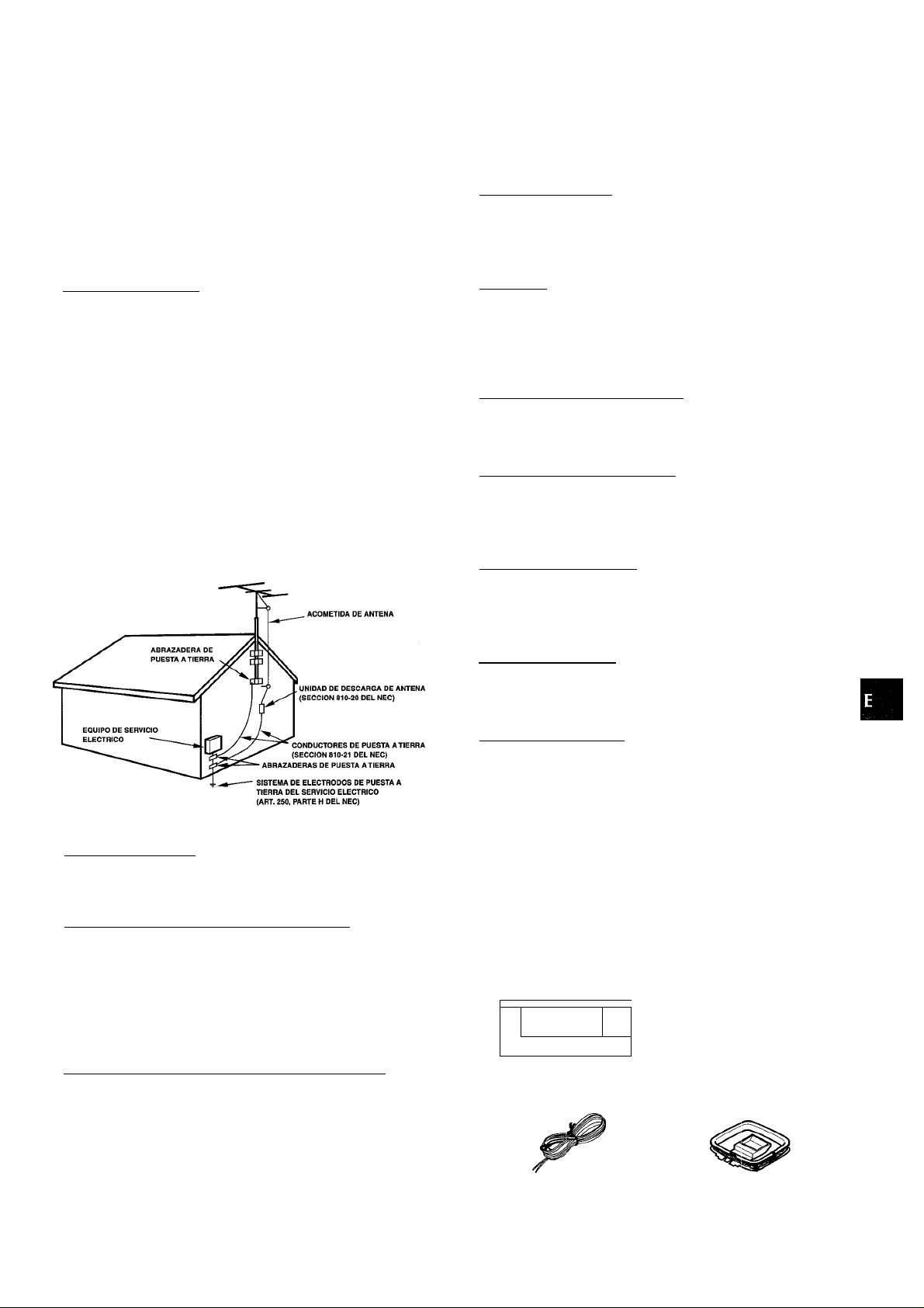
Outdoor Antenna
1 Power lines — When connecting an outdoor antenna, make
sure it is located away from power lines.
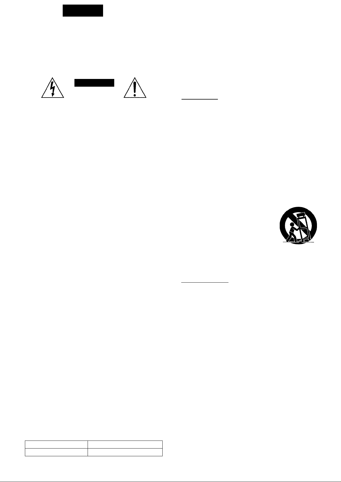
2 Outdoor antenna grounding — Be sure the antenna system
is properly grounded to provide protection against unexpected
voltage surges or static electricity build-up. Article 810 of the
National Electrical Code, ANSI/NFPA70, provides information
on proper grounding of the mast, supporting structure, and
the lead-in wire to the antenna discharge unit, as well as the
size of the grounding unit, connection to grounding terminals,
and requirements for grounding terminals themselves.
Antenna Grounding According to the National Eiectricai Code
PREPARATIONS
CONNECTIONS
BEFORE OPERATION .
SETTING THE CLOCK.
............
SOUND
CUSTOM AUDIO ADJUSTMENT...........
ELECTRONIC GRAPHIC EQUALIZER .
DSP SURROUND...................................
BASIC OPERATIONS
SELECTION OF AUDIO/VIDEO SOURCE ,
RECORDING AN AUDIO SOURCE
............
RADIO RECEPTION
MANUAL TUNING
DIRECT TUNING...............
PRESETTING STATIONS.
............
DOLBY PRO LOGIC
SELECTING DOLBY PRO LOGIC
ADJUSTING SPEAKER LEVEL BALANCE .
TIMER
__________________________
SETTING THE SLEEP TIMER
................
.......................
.10
.10
. 11
12
13
Maintenance
Clean the unit only as recommended in the Operating
Instructions.
Damage Requiring Service
Have the unit serviced by a qualified service technician if:
- The AC power cord or plug has been damaged
- Foreign objects or liquid have gotten inside the unit
- The unit has been exposed to rain or water
- The unit does not seem to operate normally
- The unit exhibits a marked change in performance
- The unit has been dropped, or the cabinet has been damaged
DO NOT ATTEMPT TO SERVICE THE UNIT YOURSELF.
Check your unit and accessories
AV-X120 Stereo receiver Remote controi
CD
1 Hi
= GOO r
FM antenna
o
AM antenna
GENERAL
CARE AND MAINTENANCE...
SPECIFICATIONS
TROUBLESHOOTING GUIDE
PARTS INDEX.................................
....................
,14
.15
16
.................................16
Operating Instructions, etc.
ENGLISH 2
Page 4
PREPARATIONS
CONNECTIONS
Before connecting the AC cord
The rated voltage of your unit shown on the rear panel is 120 V
AC. Check that the rated voltage matches your local voltage.
IMPORTANT
Connect the speakers, antennas, and all other external
equipment first. Then connect the AC cord at the end.
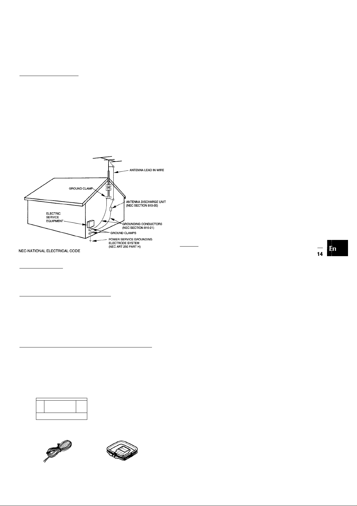
CONNECTING EQUIPMENT
Jacks and plugs of the connecting cord are color-coded as
follows:
Red jacks and plugs : For the right channel of audio signals
White jacks and plugs: For the left channel of audio signals
Yellow jacks and plugs: For video signals
Insert the plugs fully into the jacks. Loose connections may
produce a humming sound or other noise interference.
ENGLISH
Page 5
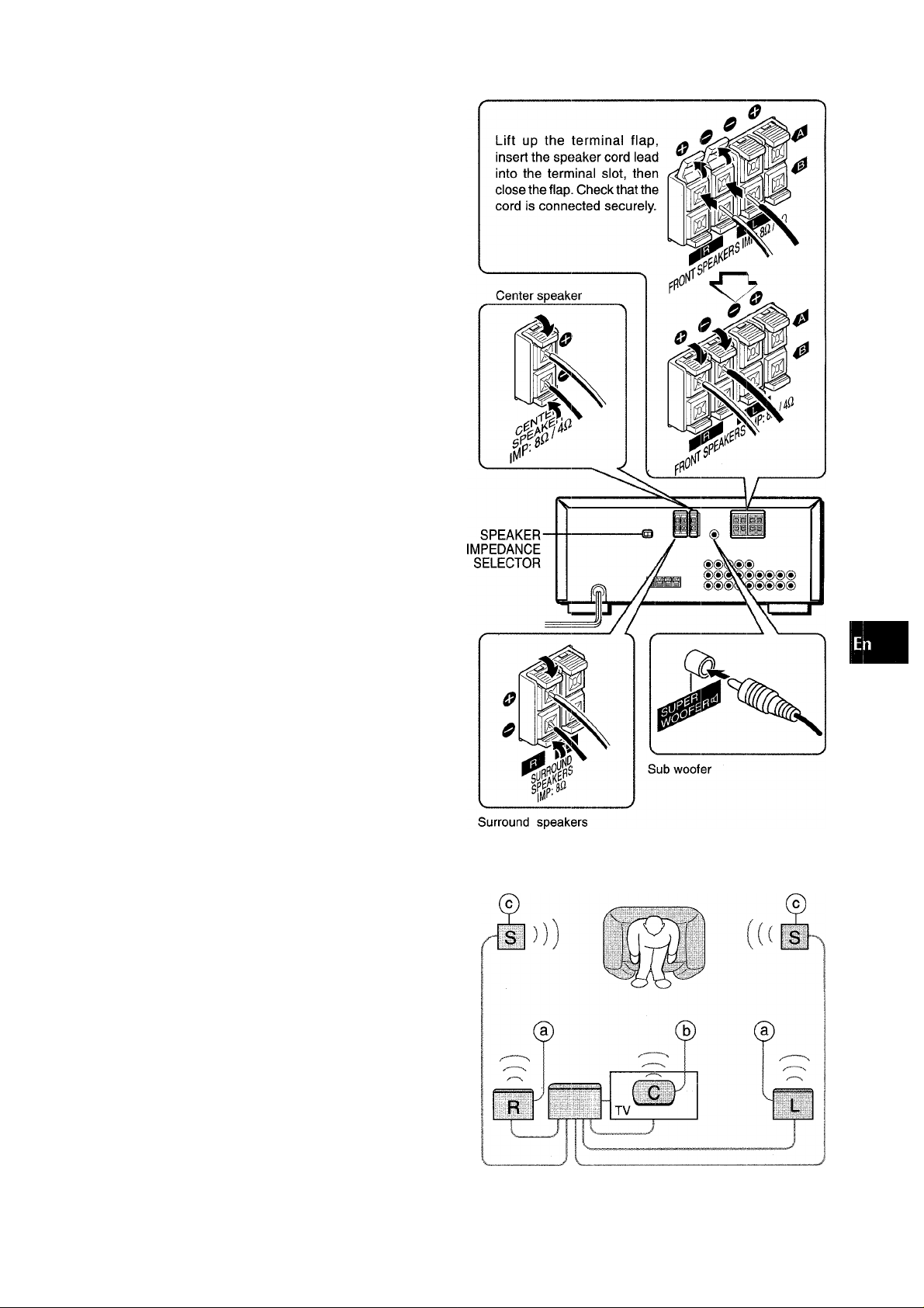
CONNECTING SPEAKERS ®
Speaker terminais
Connect front speakers (system A and/or B), a center speaker
and surround speakers to the corresponding speaker terminals
on the unit:
- the front speaker cords to the FRONT SPEAKERS terminals
- the center speaker cord to the CENTER SPEAKER terminals
- the surround speaker cords to the SURROUND SPEAKERS
terminals.
For more powerful bass, connect a sub woofer with a built-in
amplifier to the SUPER WOOFER “1 jack.
Speaker impedance
• Front and center speakers
The SPEAKER IMPEDANCE SELECTOR on the rear should be
set to the position that matches the impedance value of the front
and center speakers.
When using 4 ohm speakers, set the selector to 4£2. When using
8 ohm speakers, set the selector to 8Q. Please unplug the AC
cord before setting the selector.
• Surround speakers and super woofer
The SPEAKER IMPEDANCE SELECTOR has no effect on the
SURROUND SPEAKERS terminals and the SUPER WOOFER
jack. For the surround speakers and sub woofer, use speakers
of 8 ohms or more.
Front speakers
(/)
2!
0
1
i
a:
Q.
Connecting + to +, - to - terminals
To get the proper sound effect, the speaker terminals on the unit
and the speaker should be connected with proper polarity; the -iterminal on the unit should be connected to the -i- terminal on
the speaker (and - to -).
• Be sure to connect the speaker cords correctly as shown in
the illustration on the right column. Improper connections can
cause short circuits in the SPEAKER(S) terminals.
• Do not leave objects generating magnetism near the speakers.
• When using a sub woofer, select the speaker system A (see
page 6). Otherwise no sound can be heard from it.
POSITIONING THE SPEAKERS
Position the speakers to make the most of the Dolby Pro Logic
or DSP effect (see “DOLBY PRO LOGIC”).
(D Front speakers © Center speaker
Position in the center of the two front speakers. In addition,
position on or below the TV set, if connecting a TV set to the
unit.
© Surround speakers
Place the surround speakers directly to the side of or slightly
behind the listening area. Align them horizontally, about 1
meter (3.2 feet) above ear height.
' Sound is heard from the surround speakers when the DSP is
set to on.
' Sound is heard from the center speaker mainly when the Dolby
Pro Logic is set to on. Note that when you select the PHANTOM
mode of the Dolby Pro Logic, the center speaker is muted.
(For details, see “DOLBY PRO LOGIC”).
ENGLISH
Page 6

CONNECTING THE SUPPLIED ANTENNAS (D
Connect the FM antenna to the FM 75 n terminals and the AM
antenna to the AM LOOP terminals.
FM antenna
REMOTE CONTROL
Inserting batteries
Detach the battery cover on the rear of the remote control and
insert two R6 (size AA) batteries.
When to replace the batteries
The maximum operational distance between the remote control
and the sensor on the unit should be approximately 5 meters
(16 feet). When this distance decreases, replace the batteries
with new ones.
To stand the AM loop antenna on a surface
Fix the claw to the slot as shown in the illustration.
To position the antennas FM feeder antenna:
Extend this antenna horizontally in a T shape and fix its ends to
the wall.
AM loop antenna:
Position for the best reception.
• Do not bring the FM antenna near metal objects or curtain rails.
• Do not bring the AM antenna near other external equipment,
the unit itself, the AC power cord or speaker cords, as noise
will be picked up.
• Do not unwind the AM loop antenna wire.
Using the remote control
The instructions in this manual refer mainly to the buttons on the
main unit. Buttons on the remote control with the same names
as those on the main unit can be used as well.
• If the unit is not going to be used for an extended period of
time, remove the batteries to prevent possible electrolyte
leakage.
' The remote control may not operate correctly when:
- The line of sight between the remote control and the remote
sensor in the display window is exposed to intense light, such
as direct sunlight.
- Other remote controls are used nearby (those of television,
etc.)
CONNECTING AN OUTDOOR ANTENNA
For better FM reception, use of an outdoor antenna is
recommended. Connect the outdoor antenna to the FM 75 Q
terminals.
ENGLISH
Page 7
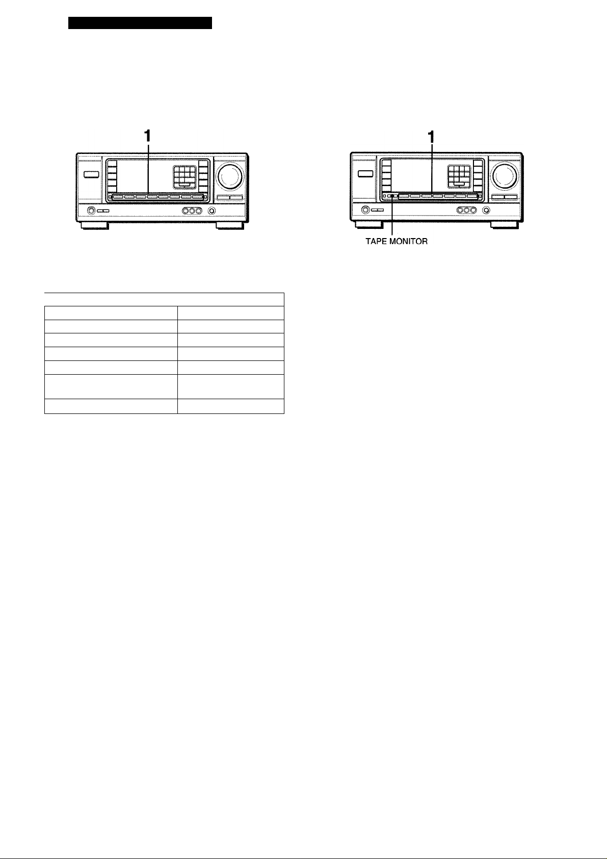
BEFORE OPERATION
TAPE MONITOR
SETTING THE CLOCK
CLOCK
I/}
;z
0
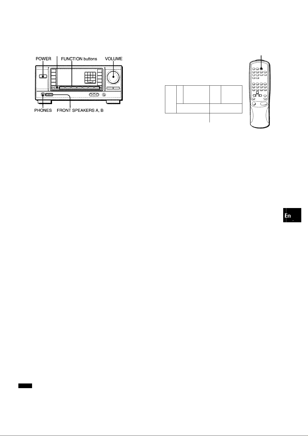
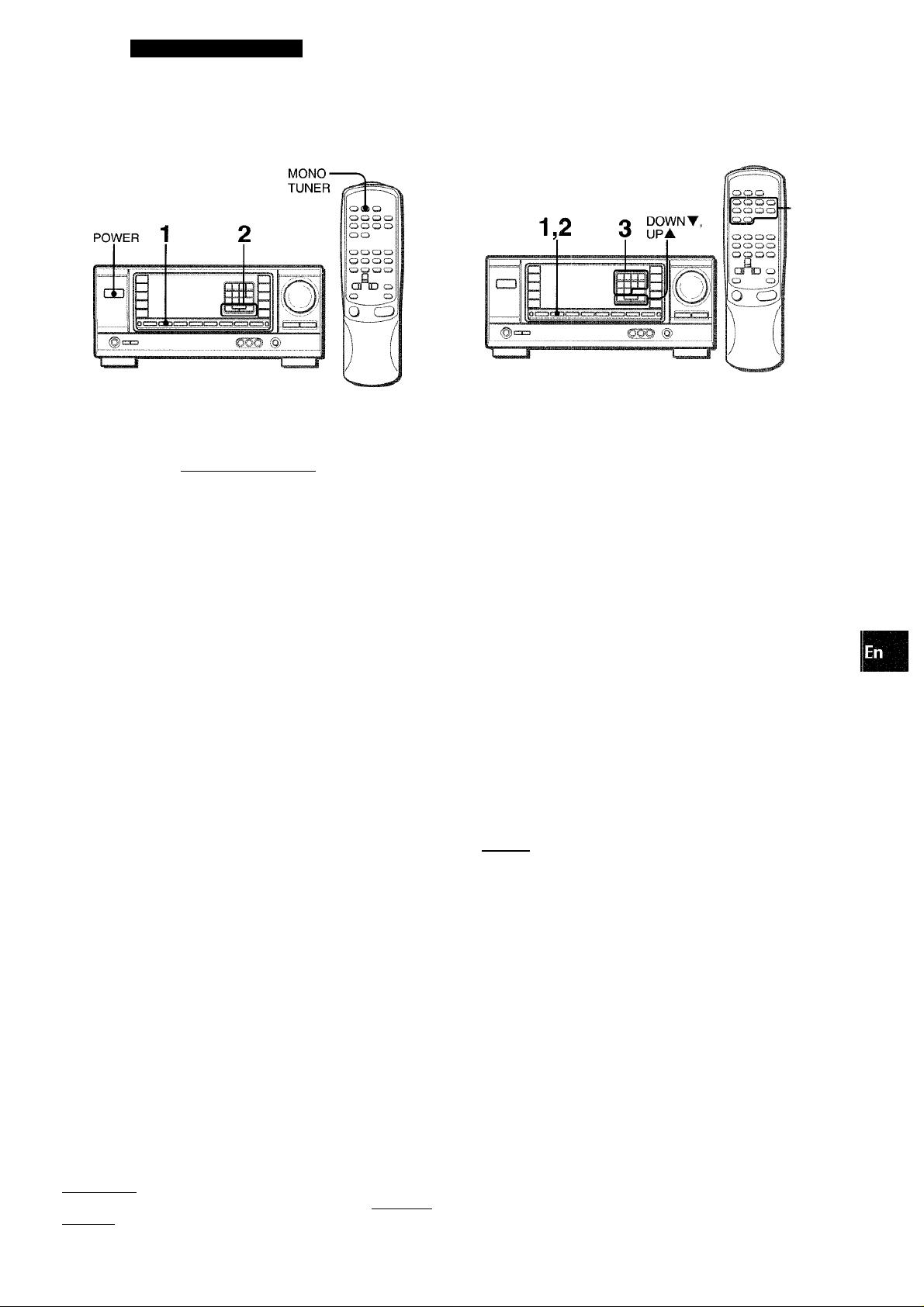
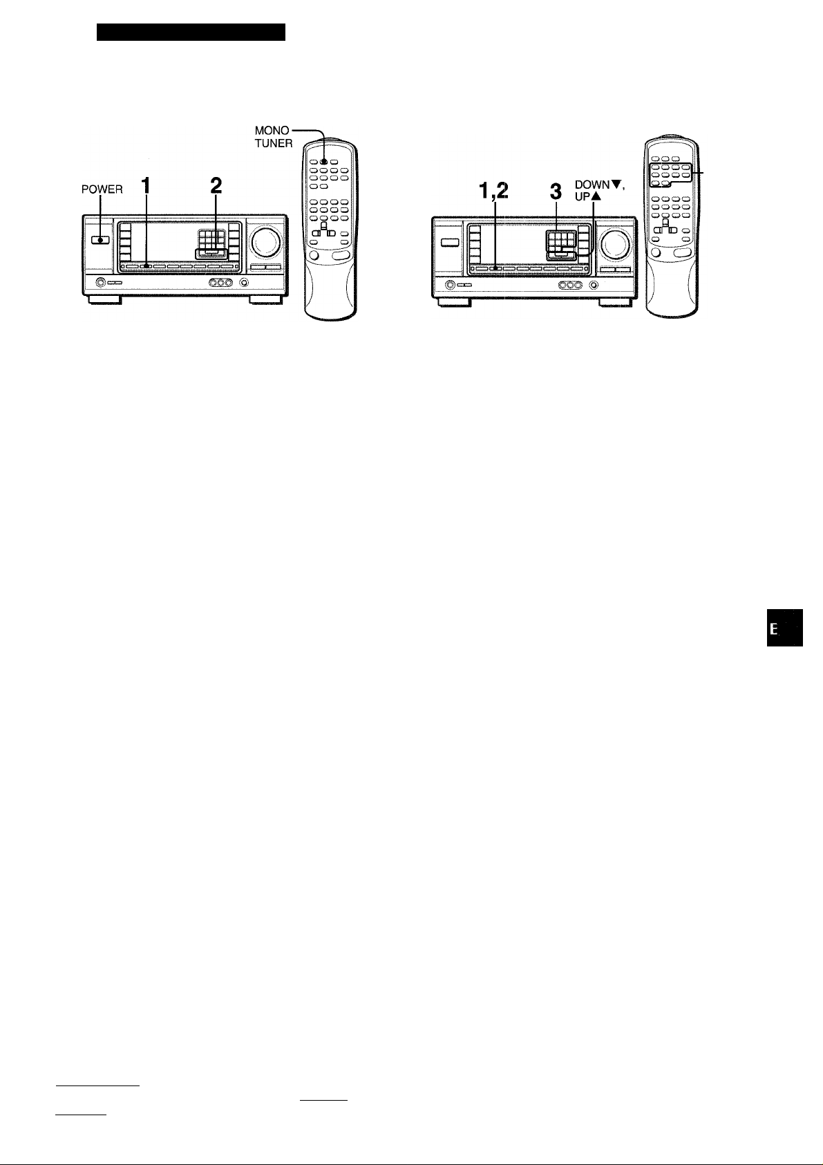
To turn the unit on
1 Turn the VOLUME control toward MIN.
Otherwise, the speakers may be damaged.
2 Press one of the FUNCTION buttons (TUNER,
PHONO, AUX/TV, CD, VIDEO 1, VIDEO 2 or
VIDEO 3) or the TAPE MONITOR button.
When pressing the TUNER button, the previously tuned
station is received (Direct Play Function).
The POWER button is also available.
Operation is possible after four seconds.
To select the front speaker system
To use speaker system A: Set the FRONT SPEAKERS A button
to *ON.
To use speaker system B: Set the FRONT SPEAKERS B button
to *ON.
To use both speaker systems : Set both the buttons to .»ON.
Set the button(s) to J.OFF to turn off the speaker system(s).
As the front speaker systems A and B are connected in series:
- The sound will be slightly decreased when using both speaker
systems
- No sound can be heard If the FRONT SPEAKERS A and B
buttons are set to .»ON when only one speaker system is
connected
To change a displayed name for the AUX/TV button and VIDEO 2 button
When the AUX/TV button is pressed, AUX is displayed initially.
It can be changed to TV.
With the power on, press the POWER button while pressing the
AUXATV button.
The displayed name for VIDEO 2 button can be changed to
VIDEO 2, LD or MD; with the power on, press the POWER button
while pressing the VIDEO 2 button.
1,3,.5
1—1
I
3=3
1_-J ........................ -TZZr
When the AC cord is connected for the first time, the clock on
the display flashes.
Set the time as follows while the power is off.
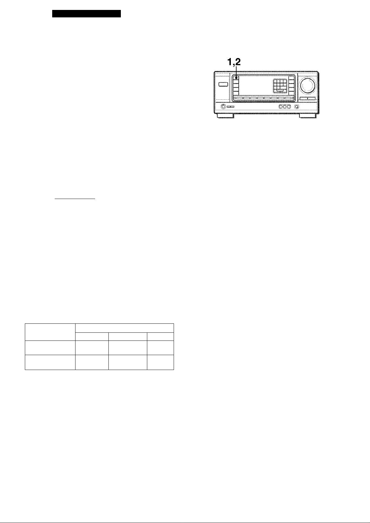
1 Press the SET button.
The hour flashes.
n n/i I ~yT"; ;■■■■■;
/■■■'/ ; ; :• ; / ;
2 Press the DOWNT or UPA button to designate
the hour.
3 Press the SET button to set the hour.
The hour stops flashing and the minute starts flashing.
4 Press the DOWNT or UPA button to designate
the minute.
5 Press the SET button to set the minute.
The minute stops flashing on the display and the clock starts
from 00 second.
To correct the current time
Press the POWER button to turn the unit off. Press the SET
button and carry out steps 1 to 5 above.
To display the current time
Press the CLOCK button on the remote control. The clock is
displayed for 4 seconds.
To switch to the 24-hour standard
Press the POWER button while pressing the UPA or DOWNV
button while the current time is displayed.
Repeat the same procedure to restore the 12-hour standard.
”(§) j
® >D
2,4
\ i /
/ '......................
1
S
IX
13.
Using the headphones
Connect headphones to the PHONES jack with a standard stereo
plug (06.3 mm, 1/4 inch). Be sure to set the FRONT SPEAKERS
A and B buttons to J.OFF. Otherwise sound is output from the
speakers.
NOTE
When using the headphones, set the Dolby Pro Logic and DSP
system to off.
To turn the unit off
Press the POWER button.
If the clock display flashes while the power is off
This is caused by a power interruption. The current time needs
to be reset.
If power is interrupted for more than approximately 24 hours, all
settings stored in memory after purchase need to be reset.
ENGLISH 6
Page 8
CUSTOM AUDIO ADJUSTMENT
MUTING VOLUME
VOLUME CONTROL
Turn the VOLUME control on the unit, or press the VOLUME
buttons on the remote control.
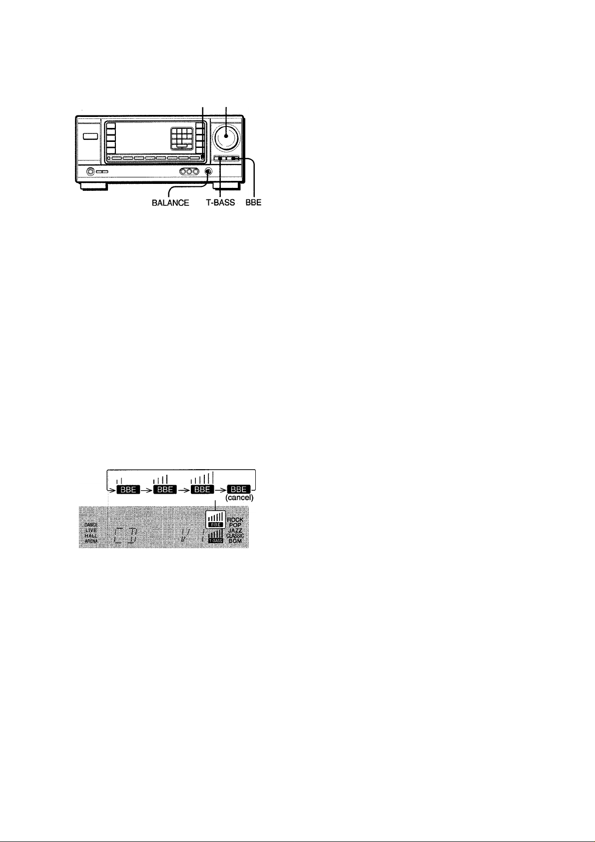
To adjust the left/right balance
Turn the BALANCE control.
SUPER T-BASS SYSTEM
The T-BASS system enhances the realism of low-frequency
sound.
Press the T-BASS button.
Each time it is pressed, the level changes. Select one of the
three levels, or the off position to suit your preference.
ROCK
POP
L VE :
.........
l-AI [ , , ,
ARENA »............
Low-frequency sound may be distorted when the T-BASS system
is used for a disc or tape in which low-frequency sound is
originally emphasized. In this case, cancel the T-BASS system.
n
JAZZ
CLASSIC
BGM
(cancel)
To mute the sound temporarily
Press the MUTING button.
"MUTE ON” appears on the display for four seconds. While muting
the sound, the Selected FUNCTION button flashes. Press the
MUTING button again to restore the sound.
BBE SYSTEM
The BBE system enhances the clarity of high-frequency sound.
Press the BBE button.
Each time it is pressed, the level changes. Select one of the
three levels, or the off position to suit your preference.
The BBE system is automatically canceled when Dolby Pro Logic
is turned on.
SOUND ADJUSTMENT DURING
RECORDING
The output volume and tone (except BBE) of the speakers or
headphones may be freely varied without affecting the level of
the recording.
Recording with the BBE
The desired source can be recorded with the BBE function to
enhance the clarity of high-frequency sound. When playing back
a tape recorded with BBE, it is recommended that BBE be set to
off.
7 ENGLISH
Page 9
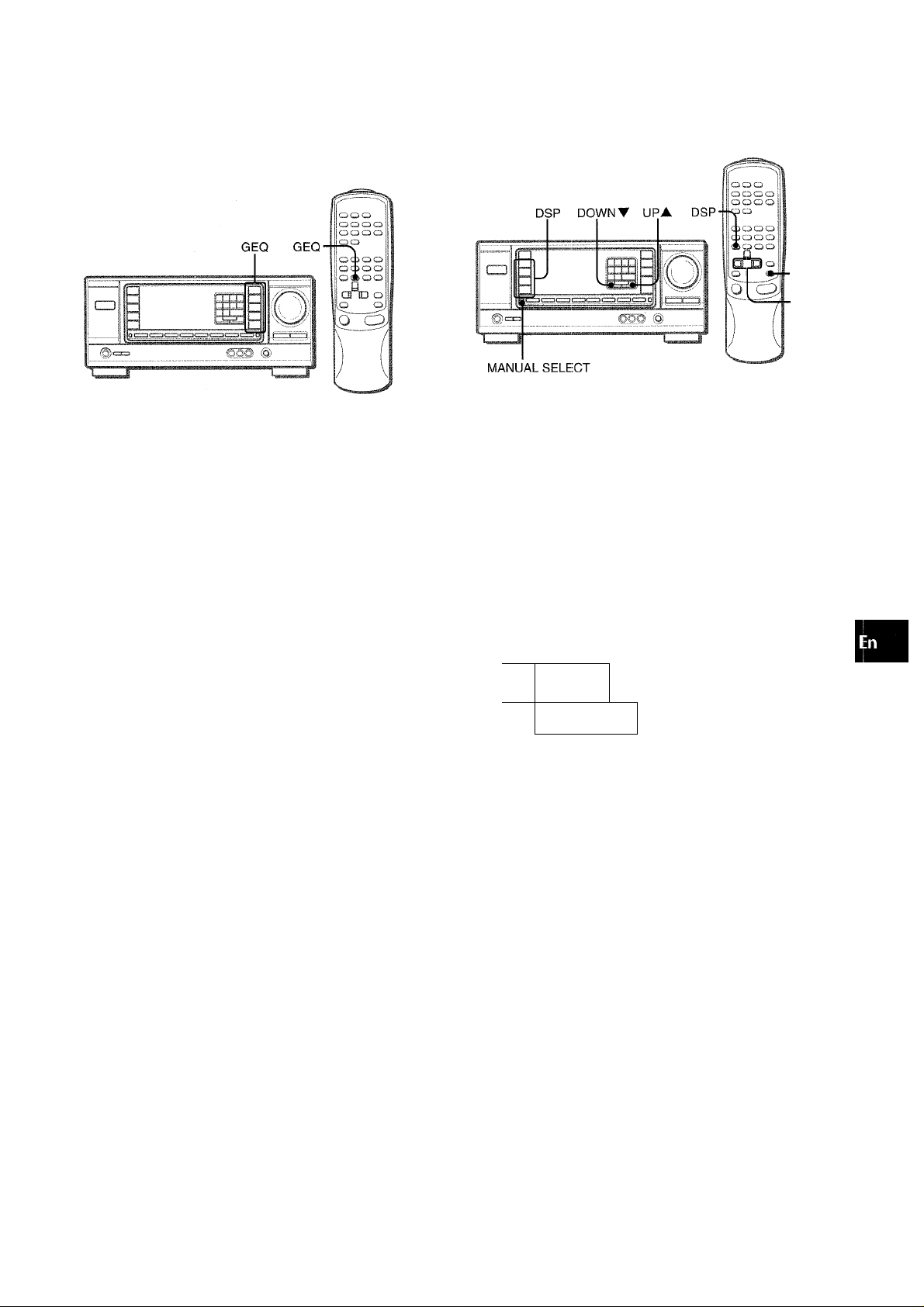
ELECTRONIC GRAPHIC EQUALIZER
This unit provides the foiiowing five different equalization modes.
ROCK: Powerfui sound emphasizing trebie and bass
POP: More presence in the vocais and midrange
JAZZ: Accented iower frequencies for jazz-type music
CLASSIC: Enriched sound with heavy bass and fine trebie
BGM: Cairn tone with suppressed bass and trebie
Press one of the GEQ (Graphic Equalizer) buttons.
The seiected mode name appears on the display for two seconds,
and the selected mode on the right side of the dispiay is enclosed
with parentheses.
DSP SURROUND
■MANUAL
SELECT
■UP^,
DOWN^
The DSP (Digitai Signal Processor) surround circuits can recreate
the effect of sounds refiected from waiis or ceiiings, to obtain the
sound presence of reai environments. There are four modes with
matching graphic equaiization modes. Equalization modes are
seiected automaticaiiy and can aiso be seiected or turned off to
suit your preference.
Press one of the DSP buttons (DANCE:, LIVE, HALL or ARENA).
The seiected mode name appears on the dispiay for two seconds,
and the seiected DSP and matching GEQ modes on the dispiay
are enciosed with parentheses.
Q
Z
:s
o
(0
Seiected mode-
OANCE
HALL
isjilpsl
; ; ; ;
\ / / /
/ I
/'■] I
I CROCK]
POR
JAZZ
ClASSIC
BGnS
To cancel the selected mode
Press the selected button again. “GEQ oFF” appears on the
dispiay.
To select with the remote control
Press the GEQ button repeatedly until the desired equalization
mode is displayed.
Seiected DSP mode Matching GEQ mode
CHOC^
.
LIVI;:
HALL
.ARENA
! i i i i\ i i !
JJ i ^ L . L .
FCF^
When the music source is monaural
Select LIVE to obtain a simulated stereo effect. When DANCE
or HALL is selected, no sound will be heard from the surround
speakers.
To cancel the selected mode
Press the selected button again. “DSP oFF” appears on the
display. Even if canceling the selected DSP mode, the matching
or selected GEQ mode still remains. While the DSP surround
system is off, no sound is heard from the surround speakers.
To select with the remote control
Press the DSP button repeatedly until the desired DSP mode is
displayed.
To adjust the volume of the surround speakers
Press the MANUAL SELECT button once. “SUR” is displayed
for four seconds. Press the UPA or DOWNV button while “SUR”
is displayed.
Note that the Dolby Pro Logic surround speakers level is also
changed (see page 13).
The DSP system is automatically canceled when the DQLBY
PRO LOGIC is turned on.
ENGLISH
8
Page 10

BASIC OPERATIONS
SELECTION OF AUOIO/VIDEO SOURCE
CZ)
m
@C3
=> Gm (
1 Select the program source.
Press one of the FUNCTION buttons or the TAPE MONITOR
button.
To listen to or watch The button pressed
Tape TAPE MONITOR
Radio TUNER
Record
Television, etc.
Compact disc
Video (VCR or LD)
MD VIDEO 2^'
For selecting AUX/TV, or VIDEO 2/LD/MD, see “To change
a displayed name for the AUX/TV button and VIDEO 2
button” of “BEFORE OPERATION” (see page 6).
PHONO
AUX/TV«>
CD
VIDEO 1, VIDEO 2"), VIDEO 3
o
f ' "'1
.......
ij
§)
RECORDING AN AUDIO SOURCE
1 Select the program source to be recorded.
Press one of the FUNCTION buttons.
2 Set the tape deck or MD recorder to the recording
mode.
3 Start the selected program source.
To monitor recorded sound during recording (when the
connected tape deck is a three-head system)
Press the TAPE MONITOR button. “TAPE ON” appears on the
display for four seconds, and then the source name selected in
step 1 comes back on. To cancel the tape monitor, press it again
so that “TAPE oFF” appears.
NOTE
Any sound control except the BBE system has no effect on
recording (see page 7).
When using a turntable with a built-in equalizer amplifier, set the
switch of the equalizer amplifier to off. See the instructions of
the turntable for further information.
2 Start the selected program source. 3 Adjust the sound.
About the video source to the monitor or TV
Selected VIDEO source
llllll ROCK
DANCE
LIVE
HALL
ANENA
V1; VIDEO 1, V2: VIDEO 2, V3: VIDEO 3
The selected video source is indicated on the display and the
video signal through the MONITOR VIDEO OUT jack is output
on the TV.
f ;
(
...
u
; /
;/
— pQp
■
ElMc
B6M
9 ENGLISH
Page 11
RADIO RICEPTION
MANUAL TUNING DIRECT TUNING
-Numbered
buttons
«Z
Q-
f i
Press the TUNER button repeatedly to select the desired band.
j ► FM ► AM —j
When the TUNER button is pressed while the power is off,
the power is turned on directly.
Press the UPA or DOWNV button to select a
station.
Each time the button is pressed, the frequency changes.
When a station is received, “TUNE” is displayed for two
seconds. During FM stereo reception, ((ic2)JI) is displayed.
втт-
"WAtc:':'
, ARfNft
} .!• !..! ! rJU
To search for a station quickly (Auto Search)
Keep the UPA or DOWNT button pressed until the tuner starts
searching for a station. After tuning in to a station, the search
stops.
To stop the Auto Search manually, press the UPA or DOWNT
button.
• The Auto Search may not stop at stations with very weak
signals.
When an FM stereo broadcast contains noise
Press the MONO TUNER button on the remote control so that
“MONO” appears on the display.
Noise is reduced, although reception is monaural.
MONO
f s t г 2 , .
DANCE
UVE
.. „HALL,.,,:
.
J. U U-MH7[M0N0I;
ПЛ
ROCK
POP
ROCK
:::E0E:':: :
JAZZ
CIASSIC,
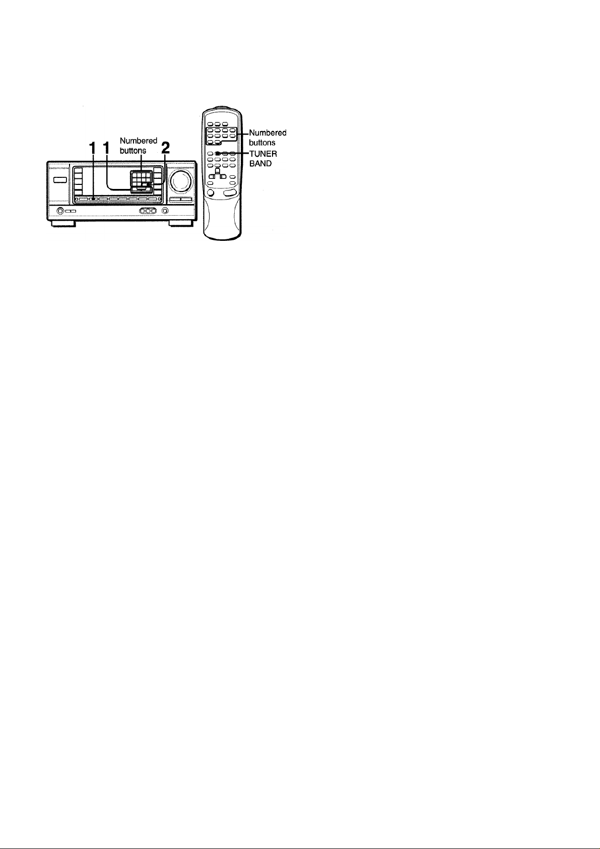
When you know the frequency of the desired station, you can
tune in directly to the station.
1 Press the TUNER button to select a band, 2 Press the TUNER button and hold it down until
hashes on the dispiay (Direct Tuning Mode).
ROCK
I/
I /
'll
POP
DANCF
1.IVE
HAUL
AH=Nft
i\ /I
I !
Press the appropriate numbered buttons to tune in to the desired station.
Example:
To tune in to 106.50 MHz, press 1,0, 6, 5 and 0 buttons.
To tune in to 95.2 MHz, press 9, 5, 2 and 0 buttons.
To cancel the Direct tuning mode
Press the UPA or DOWNT button.
When using the remote control
Carry out steps 1 and 2 above, and press the numbered buttons
on the remote control to tune in to the desired station.
l?f?S73
• When entering a frequency out of tuning range, the value
flashes for two seconds and then goes off. Check the frequency
and repeat step 3 correctly.
• When entering a frequency not covered by the tuning interval,
the value is automatically rounded up or down to the closest
one covered by it.
To restore stereo reception, press the button so that “MONO”
disappears.
To change the AM tuning interval
The default setting of the AM tuning interval is 10 kHz/step. If
you use this unit in an area where the frequency allocation system
is 9 kHz/step, change the tuning interval.
Hold down the TUNER button and press the POWER button
immediately. Note that the unit is set to the Direct Tuning mode if
the TUNER button is pressed and held down for about two
seconds.
To reset the interval, repeat this procedure.
ENGLISH 10
Page 12
PRESEniNG STATIONS
The unit can store a total of 32 preset stations. When a station is
stored, a preset number is assigned to the station. Use the preset
number to tune in to a preset station directly.
1 Press the TUNER button to select the band, and
press the UPA or DOWNT button to select a
station. Direct tuning is aiso avaiiabie.
PRESET NUMBER TUNING
1 Press the TUNER button to select a band.
2 Press the numbered buttons to select a preset
number.
Example:
To select preset number 25, press 2 and 5.
To select preset number 7, press 0 and 7.
To clear a preset station
Select the preset number of the station to be cleared. Then, press
the SET button, and press the SET button again within four
seconds.
The preset numbers of all other stations in the band with higher
numbers are decreased by one.
When using the remote control
Press the TUNER BAND button to select a band, then press the
numbered buttons to select a preset number.
2 Press the SET button to store the station.
A station is assigned a preset number, beginning from 1 in
consecutive order for each band.
Frequency
DANCE
LIVE ;—
HALL
ARENA
.; i
;
isli*
ROCK
POP
A//
CLASSiC
DGM
Preset number
3 Repeat steps 1 and 2.
No more stations will be stored if a total of 32 stations have
already been stored for all the bands.
When the AM tuning interval is changed, all preset stations are
cleared. The preset stations have to be set again.
11 ENGLISH
Page 13

DOLBY PRO LOGIC
The Dolby Pro Logic feature and the center and surround
speakers (standard) assure full-scale home theater sound. When
playing back laser discs or video software that have been
recorded in Dolby Surround, astonishingly realistic sound
surrounds the listener to create a new level of audio/visual
entertainment.
Independent control of the four channels allows the listener to
enjoy the same type of sound reproduction experienced in movie
theaters. Voices are reproduced in the front and center sound
field, while ambient sounds like cars and crowds are reproduced
on all sides of the listener for an incredibly lifelike audio/video
experience. Please read the following carefully to “tune” the
system’s output to match the characteristics of your listening
space.
Check the following:
‘ Before using the DOLBY PRO LOGIC, adjust the proper
balance of the speaker sound levels (see page 13).
• Make sure the speakers are properly connected and positioned
(see pages 3 and 4).
• Make sure the TV set and video unit are properly connected
(see page 3).
•Make sure the laser disc and video tape, etc., support
nn Ipouby surrwnp] ,
SELECTING DOLBY PRO LOGIC
TO SELECT A DOLBY PRO LOGIC MODE
Press the DOLBY PRO LOGIC button repeatedly
to select the appropriate mode.
When selecting the DOLBY PRO LOGIC or 3CH LOGIC
mode, the indicator lights up, and the selected mode name
runs through on the display. Each time the button is pressed,
the mode changes as shown below.
____
ROCK
1ШЭ POP
.Il
ilM M./Oi'.-.
BGM
DOLBY PRO LOGIC
c
DOLBY PRO LOGIC oFF (cancel) ◄——
----
!► 3CH LOGIC ■
zu
il
Q-J
The optimal Dolby Pro Logic mode depends on the type and
placement of the speakers. It is recommended that the optional
Aiwa speakers should be used for all channels, for example, the
SX-R1000 for surround speakers, the SX-C1000 for a center
speaker and the SX-AV1000 for front speakers. Check your
current type and placement of the speakers and select the
recommended Dolby Pro Logic mode accordingly.
The recommended mode
Center speaker
Larger-size Smaller-size No speaker
Surround speaker
(Rear speaker)
No surround
speaker
PHANTOM mode: Select this mode when the center speaker is
not connected. All center channel signals are redistributed to
the left and right channel speakers.
3CH LOGIC mode: Select this mode when the surround
speakers are not connected.
DOLBY PRO
LOGIC-WIDE
3CH LOGIC
WIDE
DOLBY PRO
LOGIC-NORMAL
3CH LOGIC-
NORMAL
PHANTOM
-
2 Press the DOLBY PRO LOGIC button again and
hold it down until the center speaker mode to be
selected appears.
When selecting the DOLBY PRO LOGIC mode in step 1:
“NORMAL’, “WIDE” and “PHANTOM” appear in turn.
When selecting the 3CH LOGIC mode in step 1:
“NORMAL’ and ‘WIDE” appear one after another.
> Depending on the sound source or listening condition, surround
effect may not be obtained even when the DOLBY PRO LOGIC
is on.
> The full DOLBY PRO LOGIC effect cannot be obtained when
using the software without □□|p<mYsuHBnuwD| mark. In this case,
use the DSP surround system instead (see page 8).
-The DOLBY PRO LOGIC system is automatically canceled
when the BBE or DSP system is turned on.
ENGLISH 12
Page 14

ADJUSTING SPEAKER LEVEL
BALANCE
1
2
3
The unit is equipped with a buiit-in test signal generator caiied a
noise sequencer for easy balance adjustment of all four channels.
The sequencer outputs a noise signal that “travels” from channel
to channel, enabling the simple adjustment of sound level to
achieve the same apparent loudness, at your listening position,
from each channel.
1 Select the Dolby Pro Logic mode according to
your current type and piacement of the speakers.
(See page 12.)
4 Press the MANUAL SELECT button again to stop
the noise signal.
If the surround speakers volume of the DSP Is changed (see
page 8), the Dolby Pro Logic surround speakers level is also
changed.
About the channels
The left and right speakers create the stereo effect.
The center speaker helps achieve precise sound positioning
over a broad sound field.
The rear-mounted surround speakers enhance the “depth” of
the sound field.
To change the delay time
The surround speakers reproduce sounds a split second after
the front speakers. The delay is initially set to 20 ms
(milliseconds).
To change this standard delay time, press the MANUAL SELECT
button twice or three times so that “TIME" is displayed. Then,
press the UP A or DOWNV button. Each time one of the buttons
is pressed, the delay time changes as shown below.
15ms -
► 20ms ■ 30ms
/ ii/l i
.1 . / / c:
/ / / ;
; ; / i i i !
ROCK
POP
..A//
CLASSIC
BGM
2 Press the MANUAL SELECT button and hold it
down for about two seconds until “L TEST”
appears.
ilOCK
POP
i Ì
/ ;
""i I
; i
A noise signal is sent to each channel in turn as follows:
DOLBY PRO LOGIC NORMAL or WIDE mode
(Left speaker)
'
-----
SUR: (Surround speaker)“
DOLBY PRO LOGIC PHANTOM mode
•L TEST
----
►TEST R—►SUR-
----
►TEST R: (Right speaker]I—► L TEST: I
• CEN: (Center speaker)nr)^—I
JAZZ
CLASSIC
lit
BGM
□
3CH LOGIC NORMAL or WIDE mode
-L TEST
----
►TEST R
---
►CEN-
c; □
3 Adjust the sound level of the center and (or)
surround speakers.
While “CEN” or “SUR” is displayed, press the UPA or
DOWNV button to adjust the volume of the center or surround
speakers to match the level of the left and right speakers.
To change the sound levels after adjusting the balance with the noise sequencer
The sound levels of the center and surround speakers can be
adjusted during play of a laser disc or video software.
1 Press the MANUAL SELECT button once or twice to select
“CEN” or “SUR” (center or surround).
2 While the “CEN” or “SUR” Is displayed, press the UPA or
DOWNT button to adjust the volume.
lina
i i
i\ ;
/ \! -
■ ROCK
ШШ POP
: T:
i i I i I
JA77
DOM
/ I \
To adjust the balance between the left and right speakers,
use the BALANCE control while “L TEST” or “TEST R” is
displayed.
13 ENGLISH
Page 15
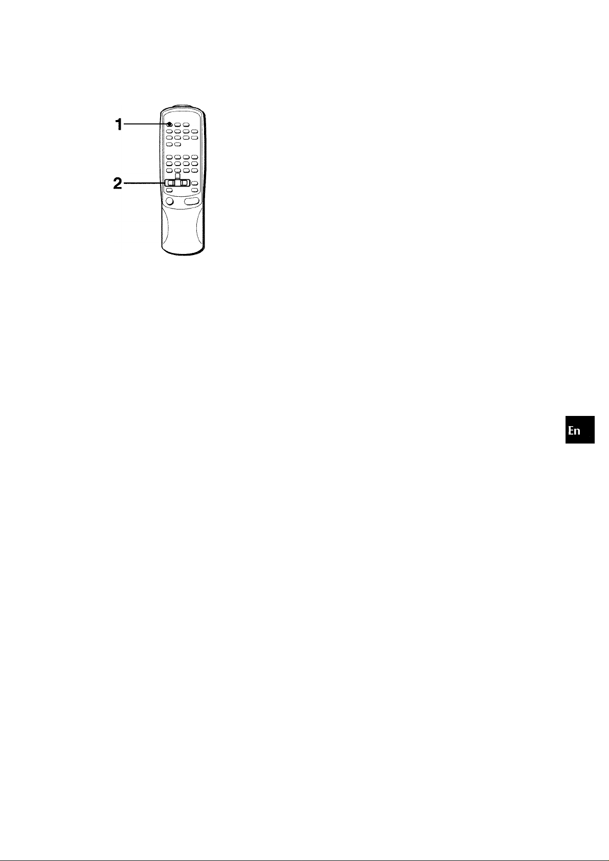
SEniNG THE SLEEP TIMER
CARE AND MAINTENANCE
Occasional care and maintenance of the unit is needed to
optimize the performance of your unit.
O
o
2 ^
The unit can be automatically turned off at a specified time.
Use the remote control.
1 Press the SLEEP button.
2 Press the UP^ or DOWN-^ button within four
seconds to specify the time untii the power is
turned off.
Each time the button is pressed, the time changes between 5
and 240 minutes in 5-minute steps.
To clean the cabinet
Use a soft dry cioth.
If the surfaces are extremely dirty, use a soft cloth lightly
moistened with mild detergent solution. Do not use strong
solvents, such as alcohol, benzine or thinner as these could
damage the finish of the unit.
iiS
m o
g
Specified time
; ; ; / ; ;
To check the time remaining untii the power is turned off
Press the SLEEP button once. The remaining time is displayed
for four seconds.
To cancel the sleep timer
Press the SLEEP button twice so that “SLEEP” on the display
disappears.
ENGLISH 14
Page 16

SPECIFICATIONS
FM tuner section
Tuning range 87.5 MHz to 108 MHz
Usable sensitivity 13.2 dBf
(IHF)
Antenna terminais 75 ohms (unbalanced)
AM tuner section
Tuning range 530 kHz to 1710 kHz (10 kHz step),
531 kHz to 1602 kHz (9 kHz step)
Usabie sensitivity 350 pV/m
Antenna Loop antenna
Ampiifier section
Power output [Stereo Mode]
Front
75 watts per channel, Min. RMS at 4
or 8 ohms, from 40 Hz to 20 kHz, with
no more than 0.8% Total Harmonic
Distortion
[Doiby Pro Logic Mode]
Front
70 watts per channel, Min. RMS at 4
or 8 ohms, from 40 Hz to 20 kHz, with
no more than 0.9% Total Harmonic
Distortion
Rear (Surround)
35 watts per channel, Min. RMS at 8
ohms, 1 kHz, with no more than 0.9%
Total Harmonic Distortion
Center
70 watts, Min. RMS at 4 or 8 ohms, 1
kHz, with no more than 0.9% Total
Harmonic Distortion
Total harmonic
distortion
Inputs
0.07 % (50 W, 1 kHz, 8 ohms. Front)
AUDIO IN
PHONO: 2.8 mV (50 kohms)
CD: 370 mV (50 kohms)
TAPE MONITOR: 200 mV (25
kohms)
VIDEO 1, VIDEO 2/LD/MD,
VIDEO 3, AUX/TV: 370 mV (50
kohms)
VIDEO IN: 1 Vp-p (75 ohms)
Outputs
Muting
AUDIO OUT (REC OUT): 230 mV (2
kohms)
VIDEO OUT (MONITOR): 1 Vp-p (75
ohms)
SUPER WOOFER: 3.1 V
FRONT SPEAKERS IMP: 80/40
selectable (front speakers A and B):
With the SPEAKER IMPEDANCE
SELECTOR set to 40, accepts
speakers of 4 ohms.
With the SPEAKER IMPEDANCE
SELECTOR set to 80, accepts
speakers of 8 ohms or more.
SURROUND SPEAKERS IMP: 80
(surround speakers): accepts
speakers of 8 ohms or more
CENTER SPEAKER IMP: 80/40
selectable
With the SPEAKER IMPEDANCE
SELECTOR set to 40, accepts
speaker of 4 ohms.
With the SPEAKER IMPEDANCE
SELECTOR set to 80, accepts
speaker of 8 ohms or more.
PHONES (stereo jack): accepts
headphones of 32 ohms or more
-20 dB
General
Power requirements 120 V AC, 60 Hz
Power consumption 160 W
Dimensions 360 x 153.5 x 335 mm (14V4 x 6Vs
(WxHxD) x13V4in.)
Weight 8.5 kg (18 lb 12 oz.)
Specifications and external appearance are subject to change
without notice.
liUU SYSTEM
The word “BBE” and the “BBE symbol” are trademarks of BBE
Sound, Inc.
Under license from BBE sound, Inc.
DOLBY PRO LOGIC
Manufactured under license from Dolby Laboratories Licensing
Corporation.
“DOLBY” the double-D symbol □□ and ’’PRO LOGIC” are
trademarks of Dolby Laboratories Licensing Corporation.
15 ENGLISH
Page 17

TROUBLESHOOTING GUIDE
PARTS INDEX
If the unit fails to perform as described in these Operating
Instructions, check the foiiowing guide.
GENERAL
There is no sound.
• Is the AC cord connected properly?
• Is there an incorrect connection? (-» page 3)
• There may be a short circuit in the speaker terminals.
-♦ Disconnect the AC cord, then correct the speaker
connections.
• Was an incorrect function button pressed?
• Are the FRONT SPEAKERS A and B buttons set correctiy?
(-* page 6)
Sound is emitted from one speaker oniy.
• Is the BALANCE control set appropriately?
• Is the other speaker disconnected?
Sound is heard at a very low volume.
• Has the MUTING button been pressed?
An erroneous display or a malfunction occurs.
Reset the unit as stated below.
TUNER SECTION
There is constant, wave-like static.
• Is the antenna connected properly? (-► page 5)
• Is the signal weak?
-► Connect an outdoor antenna.
The reception contains noise interference or the sound is
distorted.
• Is the system picking up external noise or multipath distortion?
-> Change the orientation of the antenna.
-» Move the unit away from other electrical appliances.
Instructions about each part on the unit or remote control are
indicated on the pages listed bellow.
(in alphabetic order)
Parts
AUX/TV
BALANCE
BBE
CD
CLOCK
DOLBY PRO LOGIC
DOWN T (◄)
DSP
FRONT SPEAKERS A, B
GEO
MANUAL SELECT (TEST)
MONOTUNER
MUTING, MUTE
PHONES
PHONO
POWER
SET
SLEEP
SPEAKER IMPEDANCE
SELECTOR
TAPE MONITOR
T-BASS
TUNER, BAND DIRECT
UP A(^)
VIDEO 1
VIDEO 2, LD/MD
VIDEOS
VOLUME (N/, y\)
Pages
6, 9
7,13
7
6, 9
6
12, 13
6, 8, 10, 11, 13, 14
8
6
8
8, 13
10
7
6
6, 9
6, 10
6, 11
14
4
6, 9
7
6, 9, 10, 11
6, 8, 10, 11, 13, 14
6, 9
6, 9
6, 9
7
<
OC
LU
z
LU
U
To reset
If an unusual condition in the display window or malfunction
occurs, reset the unit as follows.
1 Press the POWER button to turn off the power.
2 Press the POWER button while pressing the SET button.
Everything stored in memory after purchase is canceled.
If the power cannot be turned off in step 1 because of a
malfunction, reset by disconnecting the AC cord and carry out
step 2.
ENGLISH 16
Page 18

ESPAÑOL
ADVERTENCIA
PARA REDUCIR EL RIESGO DE INCENDIOS O
SACUDIDAS ELECTRICAS, NO EXPONGA ESTE
APARATO A LA LLUVIA NI A LA HUMEDAD.
CAUTION
RISK OF ELECTRIC SHOCK
?
“CAUTION: TO REDUCE THE RISK OF
DO NOT REMOVE COVER (OR BACK).
NO USER-SERVICEABLE PARTS INSIDE.
REFER SERVICING TO QUALIFIED
Explicación de los símbolos gráficos:
El símbolo dcl rayo con punta de flecha, en el
Interior de un triángulo equilátero, tiene la
finalidad de avisar al usuario de la presencia de
"tensiones peligrosas " sin aislar en el interior del
producto que podrían ser de suficiente magnitud
R
como para constituir un riesgo de sacudida
oicctrica para las personas.
El signo do exclamación en el interior de un
triángulo equilátero tiene la finalidad de avisar al
usuario de la presencia de Instrucciones de
operación y mantenimiento (reparación) en el
material impreso que acompaña al aparato.
DO NOT OPEN
ELECTRIC SHOCK,
SERVICE PERSONNEL.”
PRECAUCIONES
Antes de utilizar la unidad, lea cuidadosa y completamente este
manual instrucciones. Guarde el manual de instrucciones para
futuras referencias. Todos los avisos y precauciones del manual
de instrucciones y de ia unidad deberán seguirse estrictamente,
así como ias sugerencias de seguridad indicadas a continuación.
Instalación
1 Agua y humedad — No utilice esta unidad cerca del agua,
como al lado de una bañera, un lavabo, una piscina, etc.
2 Calor — No utilice esta unidad cerca de fuentes térmicas,
como salidas de calefacción, estufas, ni demás aparatos que
generen calor.
Tampoco deberá someterse a temperaturas inferiores a 5°C
(41 °F) ni superiores a 35°C (95°F).
3 Superficie de montaje — Coloque la unidad sobre una
superficie plana y nivelada.
4 Ventilación — La unidad deberá colocarse donde tenga
espacio suficiente a su alrededor para asegurar su ventilación
adecuada. Deje un espacio libre de 10 cm en la parte posterior
y superior de la unidad, y de 5 cm a cada lado.
- No la coloque sobre una cama, una alfombra, ni nada similar
que pueda bloquear las aberturas de ventilación.
- No la instale en una librería, un armario, ni un bastidor
cerrado, donde la ventilación podría ser deficiente.
5 Entrada de objetos y líquidos—Tenga cuidado de que en
el interior de la unidad no entren objetos pequeños ni
líquidos a través de las aberturas de ventilación.
6 Carritos y estantes — Cuando
haya colocado o montado la unidad
sobre un estante o un carrito,
deberá moverla con cuidado.
Las paradas repentinas, la fuerza
excesiva, o las superficies
desiguales podrían causar el vuelco
o la caída de la combinación de la unidad y el carrito.
7 Montaje en una pared o en el techo — La unidad no deberá
montarse en una pared ni en el techo, a menos que se
especifique en el manual de instrucciones.
Anotación del propietario
Para su conveniencia, anote el número de modelo y el número
de serie (los encontrará en el panel trasero de su aparato) en el
espacio suministrado más abajo. Menciónelos cuando se ponga
en contacto con su concesionario Aiwa en caso de tener
dificultades.
N.° de modelo
AV-X120
N.° de serie (N.° de lote)
Energía eléctrica
1 Fuentes de alimentación — Conecte esta unidad solamente
a las fuentes de alimentación especificadas en las
instrucciones de manejo, y como está marcado en la unidad.
2 Polarización — Como medida de seguridad, algunas
unidades disponen de enchufes de alimentación de CA
polarizados que solamente podrán insertarse de una forma
en el tomacorriente de la red. Si es difícil o imposible insertar
el enchufe de alimentación de CA en un tomacorriente de la
red, dele la vuelta e inténtelo de nuevo. Si sigue sin poder
insertarse bien, llame a un técnico de servicio cualificado
para que reemplace el tomacorriente. para evitar anular la
función de seguridad del enchufe polarizado, no lo inserte a
la fuerza en un tomacorriente.
3 Cable de alimentación de CA
- Para desconectar el cable de alimentación, tire del enchufe
de CA. No tire del propio cable.
- No tome nunca el cable de alimentación de CA con las
manos húmedas, ya que esto podría resultar en incendios
o descargas eléctricas.
- No pise el cable de alimentación ni lo pille con objetos
colocados encima o contra él, ya que podrían producirse
incendios o descargas eléctricas.
- Evite sobrecargar los tomacorrientes y los cables
prolongadores por encima de su capacidad, ya que esto
podría resultar en incendios o descargas eléctricas.
1 ESPAÑOL
Page 19
4 Cable prolongador — Para evitar descargas eléctricas, no
utilice el enchufe de alimentación de CA polarizado con un
cable prolongador ni tomacorriente a menos que el enchufe
pueda insertarse completamente a fin de evitar que sus
cuchillas queden al descubierto.
5 Períodos sin utilización — Cuando no vaya a utilizar la
unidad durante varios meses, desenchufe el cable de
alimentación de CA del tomacorriente de la red. Cuando el
cable de alimentación estás enchufado, circulará una
pequeña corriente por la unidad, incluso aunque la
alimentación esté desconectada.
INDICE
PRECAUCIONES
PREPARATIVOS
CONEXIONES....................................................................3
ANTES DE LA OPERACION
PUESTA EN HORA DEL RELOJ
...........................................................
________________________
.............................................
............
..........................6
1
6
Antena exterior
1 Líneas eléctricas — Cuando conecte una antena exterior,
cerciórese de que esté alejada de las líneas eléctricas.
2 Puesta a tierra de la antena exterior — Cerciórese de que
el sistema de antena esté adecuadamente puesto a tierra
como medida de protección contra sobretensiones
inesperadas o la generación de electrostática. El artículo
810 del código National Electric Code, ANSI/NFPA70
proporciona información sobre la puesta a tierra adecuada
del mástil, la estructura de soporte, y la acometida a la unidad
de descarga de la entena, así como sobre el tamaño de la
unidad de puesta a tierra, la conexión de los terminales de
puesta a tierra, y los requisitos de puesta a tierra de los
propios terminales.
Puesta a tierra de la antena de acuerdo con el código
National Electric Code
SONIDO
AJUSTE DEL SONIDO A SU GUSTO ..............................7
ECUALIZADOR GRAFICO ELECTRONICO.....................8
SONIDO PERIMETRICO DEL PROCESADOR
DE SEÑAL DIGITAL..........................................................8
OPERACIONES BASICAS
SELECCION DE UNA FUENTE DE AUDIIO/VIDEO
GRABACION DE UNA FUENTE DE AUDIO
ESCUCHA DE LA RADIO
SINTONIA MANUAL........................................................10
SINTONIA DIRECTA
MEMORIZACION DE EMISORAS
DOLBY PRO LOGIC
SELECCION DE DOLBY PRO LOGIC............................12
AJUSTE DEL EQUILIBRIO DEL NIVEL
ENTRE ALTAVOCES
TEMPORIZADOR
PROGRAMACION DEL
TEMPORIZADOR CRONODESCONECTADOR
_______________________________
_________________
....................
__________________
.......................................................
..................................
______________________
.....................................................
________________________
.............
.........
9
9
10
11
13
14
CODIGO ELECTRICO NACIONAL, NEC
Mantenimiento
Limpie la unidad solamente como se recomienda en el manual
de instrucciones.
Daños que requieren reparación
Haga que la unidad sea revisada por un técnico de servicio
cualificado si;
- se ha dañado el cable de alimentación o el enchufe de CA.
- en el interior de la unidad han entrado objetos o líquidos.
- la unidad ha estado expuesta a la lluvia o al agua.
- la unidad parece no funcionar normalmente.
- la unidad presenta un cambio notable en su rendimiento.
- la unidad ha caído, o se ha dañado su caja.
NO INTENTE REPARAR USTED MISMO LA UNIDAD.
GENERALIDADES
CUIDADOS Y MANTENIMIENTO
ESPECIFICACIONES
GUIA PARA LA SOLUCION DE PROBLEMAS
INDICE DE LAS PARTES............................................... 16
Compruebe su unidad y accesorios
Receptor estéreo AV-X120 Controlador remoto
r-
..........................
a
1 HI
= 650 (
Antena de FM
_______________________
....................................
......................................................
.............
O
Antena de AM
14
15
16
Manual de instrucciones, etc.
ESPAÑOL 2
Page 20

PREPARATIVOS
CONEXIONES
Antes de conectar el cable de alimentación de CA
La tensión nominal de su unidad indicada en el panel posterior
de su unidad es de 120 V CA, Compruebe si esta tensión
coincide con la de la red local.
IMPORTANTE
Conecte primero los altavoces, las antenas, y todos los demás
equipos externos. Después conecte el cable de alimentación
de CA.
CONEXION DE EQUIPOS
Las clavijas de los cables conectares y las tomas están
codificadas en color de la forma siguiente:
Clavijas y tomas rojas: Para el canal derecho de señales de
audio
Clavijas y tomas blancas: Para el canal izquierdo de señales
de audio
Clavijas y tomas amarillas: Para señales de vídeo
Inserte las clavijas de los cables conectares firmemente en las
tomas. Las conexiones flojas podrían producir zumbidos u otras
interferencias de ruido.
Page 21
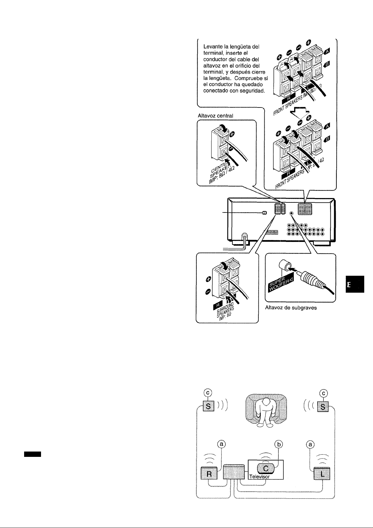
CONEXION DE LOS ALTAVOCES ®
Terminales para altavoces
Conecte los altavoces delanteros (sistema A y/o B), un altavoz
central, y altavoces perimétricos a los terminales para altavoces
correspondientes de la unidad.
- los cable de los altavoces delanteros a los terminales FRONT
SPEAKERS
- el cable del altavoz central a CENTER SPEAKER
- los cables de los altavoces perimétricos a los terminales
SURROUND SPEAKERS
Para obtener un sonido más potente, conecte un altavoz de
subgraves con altavoz incorporado a la toma SUPER WOOFER
■d.
Impedancia de los altavoces
• Altavoces delanteros y central
El selector SPEAKER IMPEDANCE SELECTOR del panel
posterior deberá ponerse en la posición correspondiente al valor
de impedancia de los altavoces delanteros y central.
Cuando utilice altavoces de 4 ohmios, ponga el selector en 4£i.
Cuando utilice altavoces de 8 ohmios, ponga el selector en 8íl.
Antes de ajustar el selector, desenchufe el cable de alimentación
de CA.
• Altavoces perimétricos y altavoz de subgraves
El selector SPEAKER IMPEDANCE SELECTOR no afecta a los
terminales SURROUND SPEAKERS ni a la toma SUPER
WOOFER “d. Para los altavoces perimétricos y el altavoz de
subgraves, utilice altavoces de 8 ohmios o más.
Conexión de los terminales + a +, y - a -
Para obtener el efecto acústico apropiado, los terminales de la
unidad y de los altavoces deberán conectarse con la polaridad
apropiada: los terminales + de la unidad deberán conectarse a
los terminales + de los altavoces (y - a -).
•
Altavoces delanteros
SPEAKER
IMPEDANCE
SELECTOR
ai
i
te
£
UJ
ir
Q.
• Cerciórese de conectar correctamente los cables de los
altavoces como se muestra en la columna de la derecha. La
conexión inapropiada podría causar cortocircuitos en los
terminales SPEAKER(S).
• Cerciórese de utilizar altavoces con la impedancia especificada.
• No coloque objetos que generen magnetismo cerca de los
altavoces.
• Cuando utilice un altavoz de subgraves, seleccione el sistema
ce altavoces A (consulte la página 6). De lo contrario, no saldría
sonido a través de él.
UBICACION DE LOS ALTAVOCES
Coloque los altavoces de forma que obtenga el máximo efecto
del sistema Dolby Pro Logic o del procesador de señal digital
(DSP) (consulte “DOLBY PRO LOGIC”).
(D Altavoces delanteros (g) Altavoz central
Colóquelo en el centro de los dos altavoces delanteros.
Además, si ha conectado un televisor a la unidad, coloque el
altavoz sobre o debajo del mismo.
© Altavoces perimétricos
Colóquelos directamente a los lados del área de escucha o
ligeramente detrás de ella. Alinéelos horizontalmente, a
aproximadamente 1 metro sobre la altura de los oídos.
NOTA
' Cuando active el procesador de señal digital, oirá sonido a
través de los altavoces perimétricos.
’ Cuando active el sistema Dolby Pro Logic, el sonido se oirá
principalmente a través del altavoz central, tenga en cuenta
que cuando haya seleccionado el modo PHANTOM de Dolby
Pro Logic, el altavoz central se silenciará. (Con respecto a los
detalles, consulte “DOLBY PRO LOGIC”.)
Altavoces perimétricos
española
Page 22
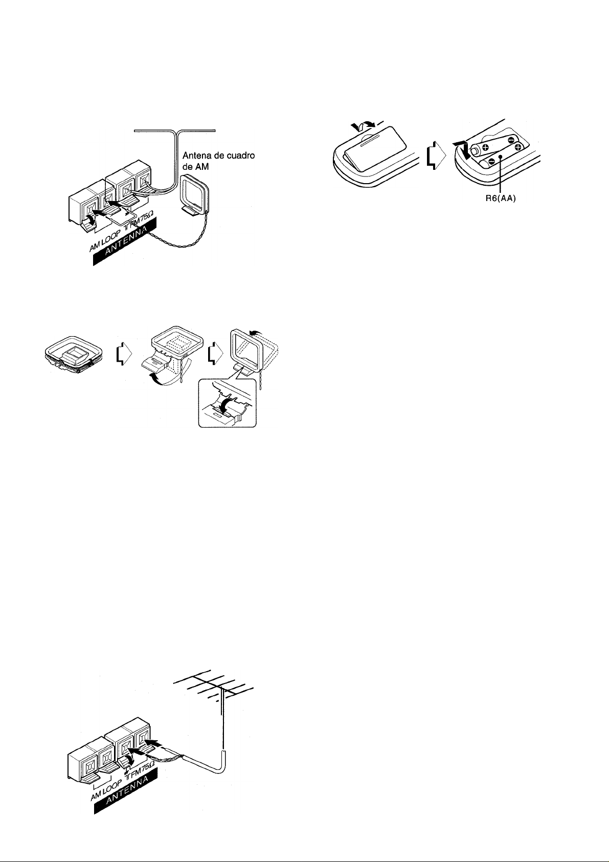
CONEXION DE LAS ANTENAS
SUMINISTRADAS ®
Conecte la antena de FM a los terminales FM 75 Í2 y la antena
de AM a los terminales AM LOOP.
Antena de FM
Para colocar la antena de cuadro de AM sobre una superficie
Fije la uña en la ranura como se muestra en la ilustración.
CONTROLADOR REMOTO
Inserción de las pilas
Quite la tapa del compartimiento de las pilas de la parte posterior
del controlador remoto e inserte dos pilas R6 (AA).
Cuándo reemplazar las pilas
La distancia máxima de operación entre el controlador remoto y
el sensor de la unidad deberá ser de aproximadamente 5 metros.
Cuando esta distancia se reduzca, reemplace las pilas por otras
nuevas.
Utilización del controlador remoto
Las instrucciones de este manual se refieren principalmente a
los botones de la unidad principal. Los botones del controlador
remoto con los mismos nombres que los de la unidad principal
también podrán utilizarse.
Ubicación de las antenas Antena en T de FM:
Extienda horizontalmente esta antena en forma de T y fije sus
extremos a una pared.
Antena de cuadro de AM:
Colóquela con la orientación óptima.
■ No acerque la antena de FM a objetos metálicos ni a rieles de
cortinas.
' No acerque la antena de AM a otros equipos externos, la propia
unidad, el cable de alimentación de CA, ni los cables de los
altavoces, porque podría captar ruido.
' No desbobine la antena de cuadro de AM.
CONEXION DE UNA ANTENA EXTERIOR
Para mejorar la recepción de FM, se recomienda utilizar una
antena exterior. Conecte la antena exterior a los terminales FM
75 Q.
' Cuando no vaya a utilizar la unidad durante mucho tiempo,
extráigale las pilas para evitar la posible fuga de su electrólito.
' Es posible que el controlador remoto no funcione correctamente
cuando:
- La línea de visión entre el controlador remoto y el sensor de
control remoto del interior del visualizador esté expuesta a
una luz intensa como, por ejemplo, la luz solar directa.
- Estén utilizándose cerca otros controladores remotos (de un
televisor, etc.).
ESPAÑOL
Page 23
ANTES DE LA OPERACION
PUESTA EN HORA DEL RELOJ
PHONES FRONT SPEAKERS A, B
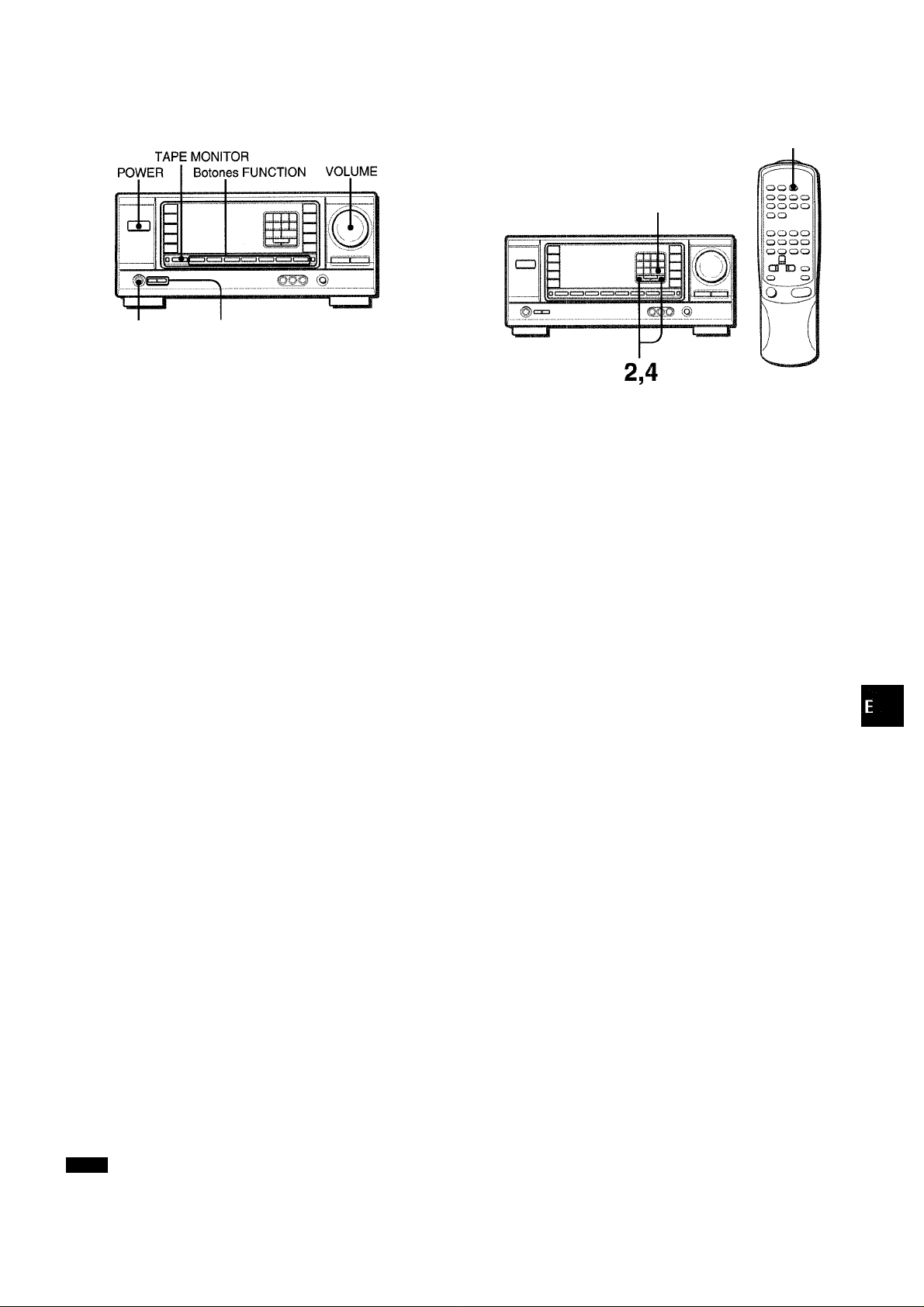
Para conectar la alimentación de ia unidad
1 Gire ei controi VOLUME hacia MIN.
De lo contrario, los altavoces podrían dañarse.
2 Presione uno de los botones FUNCTION (TUNER,
PHONO, AUX/TV, CD, VIDEO 1, VIDEO 2 o VIDEO
3) o el botón TAPE MONITOR.
Cuando presione el botón TUNER, se recibirá la emisora
previamente sintonizada (función de reproducción directa).
También podrá utilizarse el botón POWER.
La operación será posible después de cuatro segundos.
Selección del sistema de altavoces delanteros
Para utilizar el sistema de altavoces A: Ponga el botón FRONT
SPEAKERS A en *ON.
Para utilizar el sistema de altavoces B: Ponga el botón FRONT
SPEAKERS B en J1.0N.
Para utilizar ambos sistemas de altavoces: Ponga ambos
botonasen j^ON.
Para desconectar uno de los sistemas (o ambos sistemas) de
altavoces, ponga el botón (o los botones) en J.OFF.
CLOCK
1,3,5
Cuando conecte por primera vez el cable de alimentación de
CA, la indicación del reloj parpadeará.
Ajuste la hora de la forma siguiente con la alimentación
desconectada.
1 Presione el botón SET.
La hora parpadeará.
D ;\ /l — / ■■'/•'1"''/ ; /
2 Presione el botón DOWNT o UPA para designar
la hora.
3 Presione el botón SET para introducir la hora.
La hora dejará de parpadear y comenzarán a hacerlo los
minutos.
\ ■ ''
^ ; l "\i l ; ;
■ / i' -N
........
(O
o
>
g
OC
IIJ
cc
Q.
Como los sistemas de altavoces delanteros A y B están
conectados en serie:
- El sonido se reducirá ligeramente cuando utilice ambos
sistemas de altavoces.
- No se oirá sonido si los botones FRONT SPEAKERS A y B
están en jitON cuando solamente haya conectado un sistema
de altavoces.
Para cambiar el nombre visualizado para el botón AUX/
TV y el botón VIDEO 2
Cuando presione el botón AUX/TV, inicialmente se visualizará
AUX. Usted podrá cambiar la indicación a TV.
Para conectar la alimentación, presione el botón POWER
manteniendo pulsado el botón AUX/TV.
El nombre visualizado para el botón VIDEO 2 podrá cambiarse
a VIDEO 2, LD, o IVID. Con la alimentación conectada, presione
el botón POWER manteniendo pulsado el botón VIDEO 2.
Utilización de auriculares
Conecte los auriculares con clavija estéreo estándar (6,3 mm
de diá.) en la toma PHONES. Cerciórese de que los botones
FRONT SPEAKERS A y B no estén en J.OFF. De lo contrario,
el sonido saldría a través de los altavoces.
NOTA
Cuando utilice auriculares, desactive el sistema Dolby Pro Logic
y el procesador de señal digital.
Para desconectar la alimentación de la unidad
Presione el botón POWER.
4 Presione el botón DOWNT o UPA para designar
los minutos.
5 Presione el botón SET para introducir los
minutos.
Los minutos dejarán de parpadear y el reloj comenzará a
funcionar a partir de 00 segundos.
Para corregir la hora actual
Presione el botón POWER para desconectar la alimentación de
la unidad. Presione el botón SET y realice los pasos 1 a 5
anteriores.
Para hacer que se visualice la hora actual
Presione el botón CLOCK del controlador remoto,
visualizará durante 4 segundos.
Para cambiar al modo de 24 horas
Presione el botón POWER manteniendo pulsado el botón UPA
o DOWNT mientras esté visualizándose la hora actual.
Para volver al modo de 12 horas, repita el mismo procedimiento.
Si la indicación dei reioj parpadea mientras la
alimentación esté desconectada
Esto se deberá a una interrupción del suministro eiéctrico. Usted
tendrá que volver a poner en hora el reloj.
Si el suministro eléctrico se interrumpe durante más de 24 horas,
todos los ajustes almacenados en la memoria después de haber
adquirido la unidad tendrán que volver a memorizarse.
El reloj se
ESPAÑOL 6
Page 24

AJUSTE DEL SONIDO A SU GUSTO
________________
MUTING VOLUME
SISTEMA SUPER T-BASS
El sistema T-BASS realza el realismo del sonido de baja
frecuencia.
Presione el botón T-BASS.
Cada vez que presione el botón, el nivel cambiará.
Seleccione a su gusto uno de los tres niveles o la posición de
cancelación.
llIHI ROCK
Éssm POP
1/
(cancelación)
HALL
ARENA
I i :
í ¡ I
CONTROL DEL VOLUMEN
Gire el control VOLUME de la unidad o presione los botones
VOLUME del controlador remoto.
Para ajustar el equilibrio entre los canales izquierdo y
derecho
Gire el control BALANCE.
Para silenciar temporalmente el sonido
Presione el botón MUTING.
En el visuallzador aparecerá “MUTE ON” durante cuatro
segundos. Mientras el sonido esté silenciado, el botón
FUNCTION seleccionado parpadeará. Para restablecer el
sonido, vuelva a presionar el botón MUTING.
SISTEMA BBE
El sistema BBE realza la claridad del sonido de alta frecuencia.
Presione el botón BBE.
Cada vez que presione el botón, el nivel cambiará. Seleccione
a su gusto uno de los tres niveles o la posición de cancelación.
(cancelación)
à
DANCE
LIVE
HALL
ARENA
f i
¡i
! /
//
li III I ROCK
. mai POP
El sonido de baja frecuencia puede distorsionarse cuando utilice
el sistema T-BASS con un disco o un casete cuyo sonido de
baja frecuencia haya sido acentuado originalmente. En este
caso, cancele el sistema T-BASS.
AJUSTE DEL SONIDO DURANTE LA GRABACION
El volumen y el tono de salida (excepto BBE) de los altavoces o
de los auriculares podrán variarse libremente sin que se vea
afectado el nivel de grabación.
Grabación con el sistema BBE
Usted podrá grabar la fuente deseada con la función BBE para
reforzar la claridad del sonido de alta frecuencia. Para reproducir
una cinta grabada con el sistema BBE, se recomienda cancelar
tal sistema.
El sistema BBE se cancelará automáticamente cuando active el
sistema DOLBY PRO LOGIC.
7 ESPAÑOL
Page 25
ECUALIZADOR GRAFICO
SONIDO PERIMETRICO DEL
ELECTRONICO
Esta unidad dispone de los cinco modos de ecualización
siguientes.
ROCK: Acentúa el sonido de graves y agudos.
POP: Ofrece más presencia a ias voces y a la gama media.
JAZZ: Acentúa ias frecuencias bajas para música de fipo jazz.
CLASSIC: Ofrece sonido rico con graves profundos y agudos
delicados.
BGM: Ofrece tono calmado con graves y agudos suprimidos.
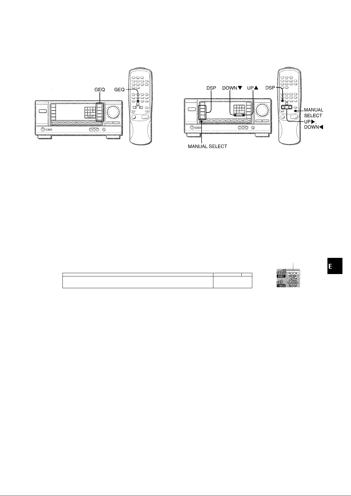
Presione uno de los botones GEQ (ecualizador gráfico).
El nombre del modo seleccionado aparecerá en el visualizador
durante dos segundos, y en se encerrará entre paréntesis en la
parte derecha del visualizador.
PROCESADOR DE SEÑAL DIGITAL
Los circuitos de sonido perimètrico del procesador de señal
digital (DSP) pueden recrear el efecto de sonidos reflejados en
paredes o techos, para ofrecer la presencia de sonido de
ambientes reales. Existen cuatro modos correspondientes a
los modos de ecualización gráfica. Los modos de ecualización
se seleccionarán automáticamente, y también podrá seleccionar
o desactivarlos a su gusto.
Presione uno de los botones DSP (procesador de
señal digital) (DANCE, UVE, HALL o ARENA)
El nombre del modo seleccionado aparecerá en el visualizador
durante dos segundos, y también se visualizarán los modos del
DSP y del GEQ adecuados.
Modo seleccionado-------------------,
sancì'
UVE
HA.CL
ARFÍ.A
..............
; ; • :• : ; ;• i JAZZ
/ 'i / / / / \ RGNÍ •
.........
iUiia r-;-
i
Para cancelar el modo seleccionado
Vuelva a presionar el botón seleccionado. En el visualizador
aparecerá “GEQ oFF’’.
Para seleccionar con el controlador remoto
Presione repetidamente el botón GEQ hasta que se visualice el
modo de ecualización deseado.
Modo del GEQ
correspondiente
ii i i i\ i i i
JJ L. C
Modo del DSP
-seleccionado
Cuando la fuente de música sea monoaural
Seleccione LIVE para obtener un efecto estéreo simulado. Si
selecciona DANCE o HALL, no oirá sonido a través de ios
altavoces perimétricos.
Para cancelar el modo seleccionado
Vuelva a presionar el botón seleccionado. En el visualizador
aparecerá “DSP oFF”. Incluso aunque haya cancelado el modo
dei DSP seleccionado, el modo del GEQ adecuado o
seleccionado permanecerá en el visualizador. Cuando desactive
ei sistema de sonido perimètrico del DSP, no oirá sonido a través
de los altavoces perimétricos.
Para seleccionar con el controlador remoto
Presione repetidamente el botón DSP hasta que se visualice el
modo de ecualización deseado.
Para ajustar el volumen de los altavoces perimétricos
Presione una vez el botón MANUAL íSELECT. En el visualizador
aparecerá “SUR” durante cuatro segundos. Presione el botón
UPA o DOWNT mientras esté visualizándose “SUR”.
Tenga en cuenta que también cambiará el nivel de los altavoces
perimétricos Dolby Pro Logic (consulte la página 13).
Cuando active el sistema DOLBY PRO LOGIC, se cancelará
automáticamente el sistema del DSF^.
ESPAÑOL
8
Page 26
OPERACIONES BASICAS
SELECCION DE UNA FUENTE DE
AUDIO/VIDEO
1 Seleccione la fuente de programas.
Presione uno de los botones FUNCTION o el botón TAPE
MONITOR.
Para escuchar o contemplar Botón presionado
Cintas TAPE MONITOR
La radio TUNER
Discos analógicos PHONO
Televisión, etc. AUX/TV=»
Discos compactos CD
Videocintas (videogravadora o VIDEO 1, VIDEO 2“),
discos láser)
Minidiscos
Para seleccionar AUX/TV o VIDEO 2/LD/MD, consulte “Para
cambiar el nombre visualizado para el botón AUX/TV y el
botón VIDEO 2” de “ANTES DE LA OPERACION” (consulte
la página 6).
VIDEO 3
VIDEO 2“)
GRABACION DE UNA FUENTE DE
AUDIO
1 Seleccione la fuente de programas que desee
grabar.
Presione uno de los botones FUNCTION.
2 Ponga el deck de casetes o el grabador de
minidiscos en el modo de grabación.
3 Ponga en reproducción la fuente de programas
seleccionada.
Para escuchar el sonido grabado durante la grabación
(cuando el deck de casetes conectado posee un sistema
de tres cabezas)
Presione el botón TAPE MONITOR. En el visualizador aparecerá
“TAPE ON” durante cuatro segundos, y después volverá a
aparecer el nombre de la fuente seleccionada en el paso 1. Para
cancelar la escucha, vuelva a presionar el botón para que
aparezca “TAPE oFF”.
Cuando utilice un giradiscos con amplificador incorporado,
desconecte la alimentación del amplificador ecualizador. Para
más información, consulte el manual de instrucciones del
giradiscos.
2 Ponga en reproducción la fuente de programas
seleccionada.
3 Ajuste el sonido.
Sobre la fuente de vídeo para el monitor o el televisor
Fuente de vídeo seleccionada
DANCE
UVE
HALL
*■«:*.*•
V1: VIDEO 1, V2: VIDEO 2, V3: VIDEO 3
La fuente de vídeo seleccionada se indicará en el visualizador,
y la señal de vídeo aplicada a la toma MONITOR VIDEO OUT
saldrá al televisor.
;;
I i
I /
■y
ROCK
POP
JAZZ
La grabación no se verá afectada por ningún controi del sonido
sin el sistema BBE (consulte la página 7).
ESPAÑOL
Page 27
ESCUCHA DE LA RADIO
SINTONIA MANUAL
1 Presione repetidamente ei botón TUNER para
seieccionar ia banda deseada.
-►AM
FM
□
Cuando presione el botón TUNER con la alimentación
desconectada, la alimentación se conectará directamente.
Presione el botón UPA o DOWNT para
seleccionar una emisora.
Cada vez que presione el botón, la frecuencia cambiará.
Cuando se reciba una emisora, se visualizará “TUNE” durante
dos segundos. Durante la recepción de FM estéreo, se
visualizará (l(QBill.
SINTONIA DIRECTA
-Botones
numéricos
Cuando conozca la frecuencia de la. emisora deseada, podrá
sintonizarla directamente.
1 Presione el botón TUNER para seleccionar una
banda.
2 Mantenga presionado el botón TUNER hasta que
en el visualizador parpadee (modo de sintonía
directa).
ll I
DANCt:
LIVF
HALL
/
r i !
I / I
ROCK
POP
üQ
«2
Íí
o<
UJU
o. (O
DAMCE
UVE
HALL ;
/ i i\ i I
¡ i I \¡ i"
ROCK
POP
Para buscar rápidamente una emisora (búsqueda automática)
Mantenga presionado el botón UPA o DOWNT hasta que el
sintonizador comience a buscar una emisora. Después de
haberse sintonizado una emisora, la búsqueda se parará.
Para parar manualmente la búsqueda automática, presione el
botón UPA o DOWNT.
• La búsqueda automática es posible que no se pare en emisoras
de señal muy débil.
Cuando un programa de radiodifusión de FM estéreo contenga ruido
Presione el botón MONO TUNER del controlador remoto para
que en el visualizador aparezca “MONO”.
El ruido se reducirá, pero la recepción será monoaural.
MONO
DANCE
UVE
HALL
A
¡\ /1
I i
i /
i/
ROCK
POP
JAZZ
CLASSIC
BGM
Para restablecer la recepción estéreo, presione el botón para
que desaparezca “MONO”.
3 Presione los botones numéricos apropiados para
sintonizar la emisora deseada.
Ejemplo:
Para sintonizar 106,50 MHz, presione los botones 1,0, 6, 5,
y 0.
Para sintonizar 95,2 MHz, presione los botones 9, 5, 2, y 0.
Para cancelar el modo de sintonía directa
Presione el botón UPA o DOWNT.
Cuando utilice el controlador remoto
Realice los pasos 1 y 2 anteriores y presione los botones
numéricos del controlador remoto para sintonizar la emisora
deseada.
• Si introduce una frecuencia fuera de la gama de sintonía, ésta
parpadeará durante dos segundos y después desaparecerá.
Compruebe la frecuencia y repita correctamente el paso 3.
• Si introduce una frecuencia no cubierta por el intervalo de
sintonía, ésta se redondeará automáticamente por defecto o
exceso a la más cercana cubierta por el intervalo de sintonía.
Para cambiar el intervalo de sintonía de AM
El ajuste inicial del intervalo de sintonía de AM es de 10 kHz/
paso. Para utilizar esta unidad donde el sistema de asignación
de frecuencias sea de 9 kHz/paso, cambie el intervalo de
sintonía.
Mantenga presionado el botón TUNER y presione
inmediatamente el botón POWER. Tenga en cuenta que si
mantiene presionado el botón TUNER durante unos dos
segundos, la unidad entrará en el modo de sintonía directa.
Para volver al intervalo anterior, repita este procedimiento.
ESPAÑOL 10
Page 28

MEMORIZACION OE EMISORAS
La unidad podrá almacenar un total de 32 emisoras. Cuando
almacene una emisora, se le asignará un número de
memorización. Utilice el número de memorización para
sintonizar directamente la emisora almacenada.
1 Presione el botón TUNER para seleccionar la
banda, y presione el botón UPA o DOWNT para
seleccionar la emisora. Usted también podrá
utilizar la sintonía directa.
SINTONIA DE EMISORAS POR SU NUMERO DE MEMORIZACION
1 Presione el botón TUNER para seleccionar una
banda.
2 Presione los botones numéricos para introducir
el número de memorización.
Ejemplo:
Para introducir el número de memorización 25, presione 2 y
5.
Para introducir el número de memorización 7, presione 0 y 7.
Para borrar una emisora memorizada
Introduzca el número de memorización de la emisora que desee
borrar. Después presione el botón SET, y antes de cuatro
segundos vuelva a presionar el botón SET.
Los números de memorización de todas las demás emisoras de
la banda de número superior se reducirán una unidad.
Quando utilice el controlador remoto
Presione el botón TUNER BAND para seleccionar la banda, y
presione los botones numéricos para introducir el número de
memorización.
2 Presione el botón SET para almacenar le emisora.
A las emisoras se les asignará un número de memorización
en orden consecutivo comenzando por 1 para cada banda.
Frecuencia
¡"s “¡ n :"i
DANCE
UVE r i\/j
HALL ; ;
AHENA * ‘ «
j "i. L.í umz
Número de memorización
i /
O
EeÍI!
ROCK
POP
JAZZ
CLASSIC
BGM
3 Repita los pasos 1 y 2.
La emisora siguiente no se almacenará si ya ha almacenado
un total de 32 emisoras para todas las bandas.
Cuando cambie el intervalo de sintonía de AM, se borrarán todas
las emisoras memorizadas. En este caso tendrá que volver a
memorizar las emisoras.
11 ESPAÑOL
Page 29
DOLBY PRO LOGIC
La función Dolby Pro Logic y los altavoces central y perimétricos
(estándar) aseguran sonido de teatro a plena para el hogar.
Cuando reproduzca discos láser o software de vídeo
especialmente grabados con Dolby Surround, un sonido
sorprendentemente realista rodeará al oyente para crear un
nuevo nivel de entretenimiento audiovisual.
El control independiente de los cuatro canales permitirá al oyente
disfrutar del mismo tipo de reproducción de sonido que el
experimentado en salas de cine. Las voces se reproducirán en
el campo acústico delantero y central, mientras que los sonidos
ambientales como el de automóviles o multitudes se reproducirá
por todos los lados del oyente y le ofrecen una experiencia
audiovisual increíblemente realista. Lea cuidadosamente lo
siguiente para “sintonizar” la salida del sistema de acuerdo con
las características de su espacio de escucha.
Compruebe lo siguiente:
• Antes de utilizar DOLBY PRO LOGIC, ajuste el equilibrio
apropiado de los niveles de sonido de los altavoces
(consulte la página 13).
• Cerciórese de que los altavoces estén adecuadamente
conectados y ubicados (consulte las páginas 3 y 4).
• Cerciórese de que el televisor y la unidad de vídeo estén
adecuadamente conectados (consulte la página 3).
• Cerciórese de que el disco láser, la videocinta, etc., sean del
sistema □□Ip«bysurr¿íííí¡51 .
PARA SELECCIONAR UN MODO DOLBY PRO LOGIC
Presione repetidamente el botón DOLBY PRO LOGIC para seleccionar el modo apropiado.
Cuando seleccione el modo DOLBY PRO LOGIC o 3CH
LOGIC, se encenderá el indicador, y en el visualizador se
desplazará el nombre del modo seleccionado. Cada vez que
presione el botón, el modo cambiará como se indica a
continuación.
ROCK
1331 POP
11
lili CLASSIC
ОЕШ PGM
o
Cq.
Xm
Ш
SELECCION DE DOLBY PRO
LOGIC
El modo Dolby Pro Logic óptimo dependerá del tipo y la ubicación
de los altavoces. Se recomienda utilizar altavoces Aiwa
opcionales para todos los canales, por ejemplo, SX-R1000 para
los altavoces perimétricos, SX-C1000 para el altavoz central, y
SX-AV1000 para los altavoces delanteros. Compruebe el tipo y
la ubicación de sus altavoces y seleccione el modo Dolby Pro
Logic recomendado correspondiente.
Modo recomendado
Altavoz central
Más grande Más pequeño Sin altavoz
Altavoces perimétricos
(altavoces traseros)
Sin altavoces
perimétricos
Modo PHANTOM: Seleccione este modo cuando no haya
conectado un altavoz central. Todas las señales del canal central
se redistribuirán a los altavoces de los canales izquierdo y
derecho.
Modo 3CH LOGIC: Seleccione este modo cuando no haya
conectado altavoces perimétricos.
DOLBY PRO
LOGIC-WIDE
ЗОН LOGIC
WIDE
DOLBY PRO
LOGIC-NORMAL
3CH LOGIC-
NORMAL
PHANTOM
-
DOLBY PRO LOGIC- -► ЗОН LOGIC
c
DOLBY PRO LOGIC oFF- (cancelación)
a
2 Mantenga presionado el botón DOLBY PRO
LOGIC hasta que aparezca el modo de altavoz
central deseado.
Cuando haya seleccionado el modo DOLBY PRO LOGIC en el paso 1 :
Aparecerán “NORMAL’, “WIDE”, y “PHANTOM”, uno tras otro.
Cuando haya seleccionado 3CH LOGIC en el paso 1 :
Aparecerán “NORMAL’ y “WIDE”, uno tras otro.
' Dependiendo de la fuente de sonido o de las condiciones de
escucha, es posible que no obtenga efecto perimètrico incuso
aunque haya activado DOLBY PRO LOGIC.
' Si utiliza software sin la marca , es posible que
no obtenga el efecto DOLBY PRO LOGIC completo. En este
caso, utilice en su lugar el sistema DSP (consulte la página 8).
' El sistema DOLBY PRO LOGIC se cancelará automáticamente
cuando active el sistema BBE o DSP.
ESPAÑOL 12
Page 30
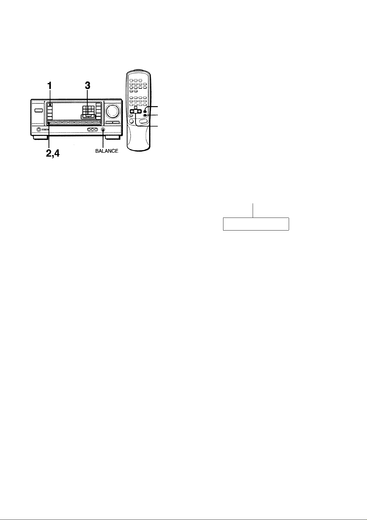
AJUSTE DEL EQUILIBRIO DEL NIVEL ENTRE ALTAVOCES
1
2
3
Esta unidad dispone de un generador de señal de prueba
incorporado denominado secuenciador de ruido para facilitar el
ajuste del equilibrio de los cuatro canales.
El secuenciador da salida a una señal de ruido que “viaja” de
canal a canal para permitir el ajuste sencillo del nivel del sonido
a fin de obtener la misma sonoridad aparente desde cada canal
en su posición de escucha.
1 Seleccione el modo Dolby Pro Logic de acuerdo
con el tipo y la ubicación de sus altavoces.
(Consulte la página 12.)
4 Para parar la señal de ruido, vuelva a presionar
el botón MANUAL SELECT.
Si cambia el volumen de los altavoces perimétricos del DSP
(consulte la página 8), cambiará también el nivel de los altavoces
perimétricos Dolby Pro Logic.
Información sobre los canales
Los altavoces izquierdo y derecho crean el efecto estéreo.
El altavoz central ayuda a ubicar con precisión el sonido en un
campo acústico amplio.
Los altavoces perimétricos montados atrás realzan la
“profundidad” del campo acústico.
Para cambiar el tiempo de retardo
Los altavoces perimétricos reproducen sonidos una fracción de
segundo después de los altavoces delanteros. Este retardo está
ajustado inicialmente a 20 ms (milisegundos).
Para cambiar este tiempo de retardo estándar, presione dos o
tres veces el botón MANUAL SELECT para que se visualice
“TIME”. Después presione el botón UPA o DOWNT. Cada
vez que presione uno de los botones, el tiempo de retardo
cambiará como se indica a continuación.
15ms •
:
..... ..... ....
; ; ; ; ;
■ 20ms - ■ 30ms
D ‘ ^ .... C
ROCK
POP
BQM
2 Mantenga presionado el botón MANUAL SELECT
durante unos dos segundos hasta que aparezca
“LTEST”.
GTSl
i /
"■/ i
A cada canal se enviará ana señal de ruido de la forma
Siguiente:
Modo DOLBY PRO LOGIC NORMAL o WIDE
L TEST: (Altavoz izquierdo) —►TEST R; (Altavoz derecho)
c
SUR: (Altavoces perimétricos) •*— GEN: (Altavoz central)
M(
Modo DOLBY PRO LOGIC PHANTOM
'L TEST—►TEST R—►SUR-
C
Modo 3CH LOGIC NORMAL o WIDE
. TEST—►TEST R
---
□
►GEN-
ROCK
POP
Cl □
3 Ajuste el nivel del sonido de los altavoces central
y (o) perimétricos.
Mientras esté visualizándose “GEN” o “SUR”, presione el
botón UPA o DOWNT para ajustar el volumen de los
altavoces central o perimétricos de acuerdo con el nivel de
los altavoces izquierdo y derecho.
Para cambiar los niveles del sonido después de haber ajustado el equilibrio con el secuenciador de ruido
Los niveles de sonido de los altavoces central y perimétricos
podrán ajustarse durante al reproducción de discos láser o
software de vídeo.
1 Presione una vez o dos el botón MANUAL SELECT para
seleccionar “CEN” o “SUR” (central o perimétricos).
2 Mientras esté visualizándose “CEN” o “SUR”, presione UPA
o DOWNT para ajustar el volumen.
I /
i
: \! ’
/ I \
Para ajustar el equilibrio entre los altavoces izquierdo y
derecho, utilice el control BALANCE mientras esté
visualizándose “LTEST” o “TEST R”.
13 ESPAÑOL
i i Ti ,,ll
______
issa
ftOCJK
Page 31
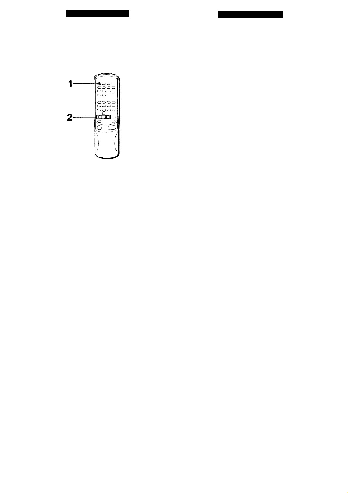
TEMPORIZADOR
GENERALIDADES
PROGRAMACION DEL TEMPORIZAOOR CRONOOESCONECTAOOR
Usted podrá hacer que la alimentación de la unidad se
desconecte automáticamente después del tiempo especificado.
Utilice el controlador remoto.
CUIDADOS Y MANTENIMIENTO
El mantenimiento y el cuidado ocasionales de la unidad serán
necesarios para sacar el máximo partido de ella.
Para limpiar el exterior
Utilice un paño suave y seco.
Si la superficie está extremadamente sucia, utiiice un paño
iigeramente humedecido en una solución poco concentrada de
detergente. No utilice disolventes fuertes, como alcohol, bencina,
o diluidor de pintura ya que podría dañar el acabado de la unidad.
3|§
5=z
ilüg
1 Presione el botón SLEEP.
; i ;
; ; ;
Presione el botón UP^ o DOWN-4 antes de cuatro segundos para especificar el tiempo hasta que se desconecte la alimentación.
Cada vez que presione el botón, el tiempo cambiará entre 5
y 240 minutos en pasos de 5 minutos.
Tiempo especificado
; ; i ;
! ;
■ "i ;
/ /
Para comprobar el tiempo restante hasta que se
desconecte la alimentación
Presione una vez el botón SLEEP. El tiempo restante se
visualizará durante cuatro segundos.
Para cancelar el temporizador cronodesconectador
Presione dos veces el botón SLEEP para que “SLEEP”
desaparezca del visualizador.
ESPAÑOL 14
Page 32

ESPECIFICACIONES
Sección del sintonizador de FM
Gama de sintonía 87,5 a 108 MHz
Sensibilidad útil 13,2 dBf
Terminales de antena 75 ohmios (desequilibrados)
Sección dei sintonizador de AM
Gama de sintonía 530 a 1710 kHz (intervalo de 10 kHz),
531 a 1602 kHz (intervalo de 9 kHz)
Sensibilidad útii 350 pV/m
Antena Antena de cuadro
Sección del amplificador
Salida de potencia [Modo estéreo]
Altavoces delanteros
75 vatios por canal como mín., valor
eficaz, a 4 ou 8 ohmios, de 40 Hz a
20 kHz, con no más del 0,8% de
distorsión armónica total
[Modo Dolby Pro Logic]
Aitavoces deianteros
70 vatios por canal como mín., valor
eficaz, a 4 ou 8 ohmios, de 40 Hz a
20 kHz, con no más del 0,9% de
distorsión armónica total
Altavoces traseros (perimétricos)
35 vatios por canal como mín., valor
eficaz, a 8 ohmios, 1 kHz, con no más
del 0,9% de distorsión armónica total
Altavoz central
70 vatios como mín., valor eficaz, a 4
ou 8 ohmios, 1 kHz, con no más del
0,9% de distorsión armónica total
Distorsión armónica
tota i
Entradas
0,07 % (50 W, 1 kHz, 8ohms,
Altavoces delanteros)
AUDIO IN
PHONO: 2,8 mV (50 kiloohmios)
CD: 370 mV (50 kilohmios)
TAPE MONITOR: 200 mV (25
kiloohmios)
VIDEO 1, VIDEO 2/LD/MD,
VIDEO 3, AUX/TV: 370 mV (50
kiloohmios)
VIDEO IN: 1 Vp-p (75 ohmios)
Salidas
Siienciamiento
AUDIO OUT (REO OUT): 230 mV (2
kiloohmios)
VIDEO OUT (MONITOR): 1 Vp-p (75
ohmios)
SUPER WOOFER: 3,1 V
FRONT SPEAKERS IMP: 80/40
seleccionable (altavoces delanteros A
yB) :
Con el selector SPEAKER
IMPEDANCE SELECTOR en 40,
aceptará altavoces de 4 ohmios.
Con el selector SPEAKER
IMPEDANCE SELECTOR en 80,
aceptará altavoces de 8 ohmios o
más.
SURROUND SPEAKERS IMP: 80
(altavoces perimétricos): acepta
altavoces de 8 ohmios o más
CENTER SPEAKER IMP: 80/40
seleccionable
Con el selector SPEAKER
IMPEDANCE SELECTOR en 40,
aceptará altavoces de 4 ohmios.
Con el selector SPEAKER
IMPEDANCE SELECTOR en 80,
aceptará altavoces de 8 ohmios o
más.
PHONES (toma estéreo): Acepta
altavoces de 32 ohmios o más
-20 dB
Sección general
Alimentación 120 V CA, 60 Hz
Consumo 160 W
Dimensiones (AN x Ai x Prf)
360 X 153,5 X 335 mm (14V4 x 6Vs x
13V4 pulgadas)
Peso 8,5 kg (18 Ib 12 oz.)
Las especificaciones y el aspecto externo están sujetos a cambio
sin previo aviso.
oau SYSTEM
Las siglas “BBE” y el “símbolo BBE” son marcas comerciales de
BBE Sound Inc.
Con licencia de BBE Sound Inc.
DOLBY PRO LOGIC
Fabricados con licencia de Dolby Laboratories Licensing
Corporation.
DOLBY y el símbolo de la D doble □□, y “PRO LOGIC” son
marcas de Dolby Laboratories Licensing Corporation.
15 ESPAÑOL
Page 33

GUIA PARA LA SOLUCION DE
INDICE DE LAS PARTES
PROBLEMAS
Si la unidad no funciona como se describe en este Manual de
instrucciones, compruebe la guía siguiente.
SECCION GENERAL
No hay sonido.
• ¿Está adecuadamente conectado el cable de alimentación de
CA?
• ¿Hay alguna conexión incorrecta? (-► página 3)
• Es posible que los terminales de los altavoces estén
cortocircuitados.
-* Desconecte el cable de alimentación de CA y corrija las
conexiones de los altavoces.
• ¿Ha presionado un botón de función incorrecto?
• ¿Ha ajustado correctamente los botones FRONT SPEAKERS
A y B? (-+ página 6)
El sonido solamente sale a través de un altavoz.
• ¿Está adecuadamente ajustado el control BALANCE?
• ¿Está desconectado el otro altavoz?
El sonido se oye con un volumen muy bajo.
• ¿Ha presionado el botón MUTING?
La visualización es errónea o se produjo un mal
funcionamiento.
-» Reponga la unidad como se indica más abajo.
SECCION DEL SINTONIZADOR
Hay estáticos constantes en forma de onda.
• ¿Está adecuadamente conectada la antena? (-♦ página 5)
• ¿Es débil la señal de FM?
-» Conecte una antena exterior.
La recepción contiene interferencias de ruido o el sonido
se oye distorsionado.
• ¿Está el sistema captando ruido externo o distorsión de
múltiples trayectorias?
—► Cambie la orientación de la antena.
-► Aleje la unidad de otros aparatos eléctricos.
Las instrucciones sobre cada parte de la unidad o del controlador
remoto se indican en las páginas mostradas a continuación.
(en orden alfabético)
Partes
AUX/TV
BALANCE
BBE
CD
CLOCK
DOLBY PRO LOGIC
DOWN T (◄)
DSP
FRONT SPEAKERS A, B
GEQ
MANUAL SELECT (TEST)
MONO TUNER
MUTING, MUTE
PHONES
PHONO
POWER
SET
SLEEP
SPEAKER IMPEDANCE
SELECTOR
TAPE MONITOR
T-BASS
TUNER, BAND DIRECT
UP A(^)
VIDEO 1
VIDEO 2, LD/MD
VIDEO 3
VOLUME (V, /\)
Páginas
6, 9
7, 13
7
6, 9
6
12, 13
6, 8, 10, 11, 13, 14
8
6
8
8, 13
10
7
6
6, 9
6, 10
6, 11
14
4
6, 9
7
6, 9, 10, 11
6, 8, 10, 11, 13, 14
6, 9
6, 9
6, 9
7
(/)
g
<
Q
□
<
DC
LU
Z
UJ
O
Reposición
Si hay alguna visualización anormal o se produce un mal
funcionamiento, reponga la unidad de la forma siguiente.
1 Presione el botón POWER para desconectar la alimentación.
2 Presione el botón POWER manteniendo pulsado el botón
SET. Todos los ajustes almacenados en la memoria después
de haber adquirido la unidad se borrarán.
Si no puede desconectar la alimentación en el paso 1 debido a
algún mal funcionamiento, reponga la unidad desconectando el
cable de alimentación de CA, y después realice el paso 2.
ESPAÑOL 16
Page 34

FRANÇAIS
AVERTISSEMENT
POUR REDUIRE LE RISQUE DE COURT-CIRCUIT OU
DE CHOC ELECTRIQUE. NE PAS EXPOSER CET
APPAREIL A LA PLUIE OU A L'HUMIDITE.
CAUTION
RISK OF ELECTRIC SHOCK
DO NOT OPEN
"CAUTION: TO REDUCE THE RISK OF
DO NOT REMOVE COVER (OR BACK).
NO USER-SERVICEABLE PARTS INSIDE.
REFER SERVICING TO QUALIFIED
Signification dos symboies graphiques:
L'cclair portant une flèche, situé dans un triangle
équilatéral, sert à prévenir l'utilisateur de la
B
ELECTRIC SHOCK.
SERVICE PERSONNEL"
présence d'une "tension dangereuse" non isolée
à l'intérieur de l'appareil, assez élevée pour
constituer un risque d'électrocution.
Le point d'exclamation situé dans un triangle
équilatéral, sert à prévenir l'utilisateur de la
presence d'instructions importantes concernant
l'utiiisation et l'entretien (ou ia réparation) de
l'appareil dans le manuel qui accompagne ce
PRECAUTIONS
Lisez attentivement et complètement le mode d’emploi avant
d’utiliser l’ampli-tuner et conservez-le pour toute référence future.
Respectez tous les avertissements et consignes mentionnés
dans le mode d’emploi, ainsi que les conseils concernant la
sécurité.
Installation
1 Eau et humidité — Ne pas utiliser l’ampli-tuner près d’une
baignoire, d’un lavabo, d’une piscine ou de tout autre endroit
similaire.
2 Chaleur — Ne pas utiliser l’ampli-tuner près d’une source de
chaleur, comme une sortie d’air chaud, un chauffage, ou autre
appareil produisant de la chaleur. Il ne doit pas non plus être
exposé à des températures inférieures à 5°C (41 °F) ou
supérieures à 35°C (95°F).
3 Installation — Installez l’ampli-tuner sur une surface plane,
de niveau.
4 Ventilation — Laissez un espace suffisant tout autour de
l’ampli-tuner pour garantir une bonne ventilation, soit environ
10 cm (4 po.) à l’arrière et au-dessus de l’ampli-tuner et 5 cm
(2 po.) sur les deux côtés.
- Ne pas poser l’ampli-tuner sur un lit, une couverture ou
toute autre surface similaire qui pourrait bloquer les orifices
de ventilation.
- Ne pas installer l’ampli-tuner dans une étagère, un placard
ou un meuble où la ventilation est insuffisante.
5 Objets et liquide — Veillez à ce qu’aucun objet ni liquide ne
pénètre dans les orifices de ventilation de l’ampli-tuner.
6 Chariots et supports — Quand
vous installez l’ampli-tuner sur un
support ou un chariot, déplacez-les
lentement.
A cause d’arrêts subits, de
mouvements brusques et de
surfaces inégales, l’ampli-tuner ou
le chariot peuvent être renversés.
7 Fixation au mur ou au plafond — L'ampli-tuner ne doit pas
être installé au mur ou au plafond.
Relevé du propriétaire
Pour plus de commodité, noter le numéro de modèle et le numéro
de série (cas numéros se trouvent au dos de l'appareil) dans les
cases ci-dessous. Prière de mentionner ces numéros quand on
contacte un distributeur Aiwa en cas de difficulté.
№ de modèle № de série (№ de lot)
AV-X120
1 FRANÇAIS
Electricité
1 Sources d’alimentation — Raccordez l’ampli-tuner
seulement à la source d’alimentation spécifiée dans le mode
d’emploi et indiquée sur l’ampli-tuner proprement dit.
2 Polarisation — Par mesure de sécurité, certains appareils
sont équipés d’une fiche secteur polarisée qui ne rentre dans
la prise murale que dans un seul sens. S’il n’est pas possible
d’insérer la fiche dans la prise, essayez dans l’autre sens.
S’il n’est toujours pas possible d’insérer la fiche dans la prise,
faites appel à un électricien pour remplacer la prise qui est
probablement trop vieille. Ne pas modifier la fiche polarisée,
elle ne remplirait plus son but.
3 Cordon d’alimentation secteur
- Quand vous débranchez le cordon d’alimentation secteur,
tirez sur la fiche et non pas sur le cordon.
- Ne jamais toucher la fiche secteur avec des mains humides
afin d’éviter les risques d’incendie ou d’électrocution.
- Les cordons d’alimentation doivent être fixés correctement
pour éviter qu’ils ne soient pliés, coincés ou piétinés. Faites
particulièrement attention au cordon reliant l’ampli-tuner à
la prise secteur.
- Evitez de surcharger les fiches et cordons de prolongation
au-delà de leur capacité afin d’éviter tout risque d’incendie
ou d’électrocution.
4 Cordon de prolongation — Afin d’éviter tout risque
d’électrocution, ne pas utiliser de fiche secteur polarisée avec
un cordon de prolongation, douille ou autre type de prise à
moins que la fiche polarisée ne soit complètement insérée
sans laisser les lames à découvert.
Page 35
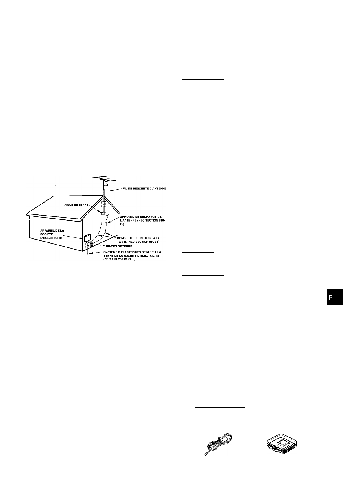
5 Quand l’ampli-tuner n’est pas utilisé — Débranchez l’ampli-
tuner de la prise secteur si vous prévoyez de ne pas l’utiliser
pendant plusieurs mois. Quand le cordon est branché, une
petite quantité d’électricité s’écoule vers même s’il est hors
tension.
TABLE DES MATIERES
PRECAUTIONS...........................................................r....1l
Antenne extérieure
1 Lignes électriques — Quand vous raccordez une antenne
extérieure, assurez-vous qu’elle est suffisamment éloignée
des lignes électriques.
2 Prise de terre de l’antenne extérieure — Assurez-vous que
l’antenne est raccordée correctement à la terre par mesure
de protection contre les pointes de tension et l’accumulation
de charges statiques. L’article 810 du Code Electrique
National, ANSI/NFPA70, fournit des informations pour une
mise à la terre correcte des mâts et supports, la mise à la
terre du fil de connexion à un appareii de décharge, la
dimension de l’appareil de décharge, la connexion des
électrodes de terre et les exigences que doivent remplir les
électrodes de terre.
Mise à la terre d’une antenne d’après le Code Electrique National
PREPARATIFS
RACCORDEMENTS
AVANT DE COMMENCER.................................................6
REGLAGE DE L'HORLOGE
SON
______________________________________
REGLAGE PERSONNEL DU SON....................................7
EGALISEUR GRAPHIQUE ELECTRONIQUE...,
PROCESSEUR D'AMBIANCE...........................................8
OPERATIONS DE BASE
SELECTION D’UNE SOURCE AUDIO OU VIDEO
ENREGISTREMENT D'UNE SOURCE AUDIO
_____________________________
..........................................................
.........
.....................................6
..............
_______________________
............
.................
RECEPTION RADIO__________________________
ACCORD MANUEL..........................................................10
ACCORD DIRECT............................................................10
PREREGLAGE DES STATIONS ....................................
DOLBY PRO LOGIC
SELECTION DU DOLBY PRO LOGIC
REGLAGE DE LA BALANCE DU NIVEAU DES
ENCEINTES
...................................................................
_________________________
............................
11
12
13
3
8
9
9
NEC-NATIONAL ELECTRIC CODE (CODE
ELECTRIQUE NATIONAL)
Entretien
Nettoyez l’ampli-tuner comme indiqué dans le mode d’emploi.
Réparations exigeant l’intervention d’un professionnel
Faites réparer l’ampli-tuner par un professionnel dans les cas
suivants:
- Le cordon ou la prise secteur a été endommagé
- Des objets ou liquides sont tombés dans l’ampli-tuner
- Lampli-tuner a été exposé à la pluie ou à l’eau
- L’ampli-tuner ne semble pas fonctionner correctement
- Les performances de l’ampli-tuner ne sont plus les mêmes
- Lampli-tuner est tombé ou le coffret a été endommagé
NE PAS ESSAYER DE REPARER SQI-MEME LE RECEPTEUR.
MINUTERIE
REGLAGE DE LA MINUTERIE D'ARRET
GENERALITES
SOIN ET ENTRETIEN
SPECIFICATIONS............................................................15
EN CAS DE PANNE
NOMENCLATURE
Vérifiez votre appareil et les accessoires
Ampli-tuner stéréo AV-X120 Télécommande
________________________________
......................
_____________________________
......................................................
........................................................
...........................................................
1 BS
=> OÜO c
O
i>
14
14
16
16
Antenne FM
Mode d’emploi, etc.
Antenne AM
FRANÇAIS 2
Page 36
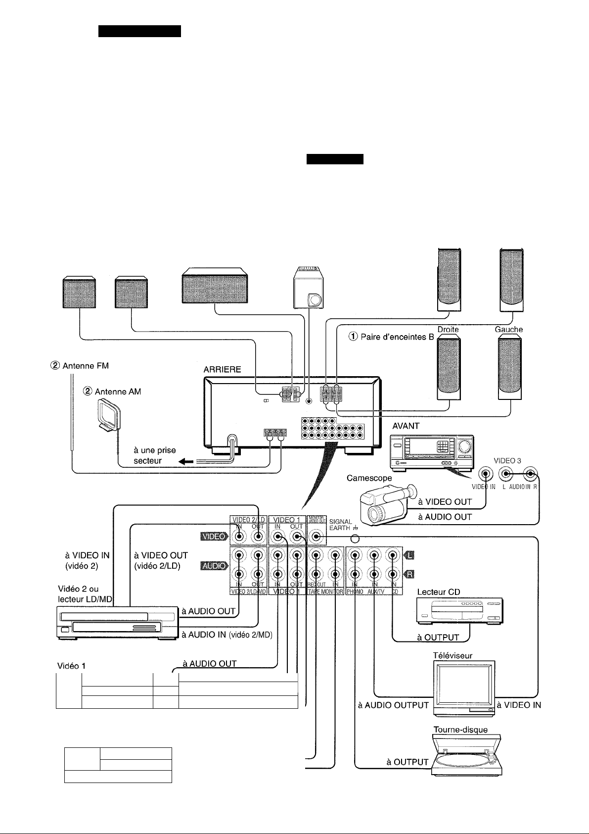
PREPARATIFS
RACCORDEMENTS
RACCORDEMENT DE TOUT L'EQUIPEMENT
Les prises et les fiches des cordons de liaison sont codées
Avant de raccorder le cordon secteur
La tension nominale de i’ampli-tuner indiquée sur le panneau
arrière est de 120 V. Vérifiez si eiie correspond à la tension locale.
IMPORTANT
Raccordez les enceintes, les antennes et les autres appareils
en premier. Raccordez le cordon secteur en dernier.
Les numéros sur l’illustration ci-dessous correspondent aux explications qui suivent dans le mode d’emploi.
© Enceinte surround 0 Enceinte centrale © Caisson de grave
Droite Gauche
couleur de la façon suivante:
Prises et fiches rouges: Canal droit des signaux audio
Prises et fiches blanches: Canal gauche des signaux audio
Prises et fiches jaunes: Signaux vidéo
REMARQUE
Insérez les fiches à fond dans les prises. Des connexions
relâchées peuvent produire un bourdonnement ou d’autres
interférences.
Cj) Paire d’enceintes A
Droite Gauche
a
—
à VIDEO OUT
à AUDIO IN .
à VIDEO IN
* Si vous raccordez une source vidéo monophonique,
utilisez un cordon de liaison stéréo-mono (non fourni)
Platine à cassette
'
- - - - - - - - - - - - - - - - - - - - - - - -
rn
£j ' ' ' . . . . . . . . . . . . . . . . . . . . . . . . . . . . . . . . . . . . . . . . . . . . . . . . . . . . . . . . . . . . . .
1 II II
à LINE IN
l=J
à LINE OUT
3 FRANÇAIS
Page 37

RACCORDEMENT DES ENCEINTES©
Bornes d’enceinte
Raccordez les enceintes avant (paire A et/ou B), une enceinte
centrale et des enceintes surround aux bornes d’enceintes
correspondantes de l’ampli-tuner:
- les cordons d’enceintes avant aux bornes FRONT SPEAKERS
- le cordon d’enceinte centrale aux bornes CENTER SPEAKER
- les cordons d’enceinte surround aux bornes SURROUND
SPEAKERS.
Pour obtenir des basses encore plus puissantes, vous pouvez
raccorder un caisson de grave amplifié à la prise SUPER
WOOEER
Impédance des enceintes
• Enceintes avant et arriére
Le sélecteur SPEAKER IMPEDANCE SELECTOR à l’arriàre de
l’ampli-tuner doit àtre réglé sur la position correspondant à
l’impédance des enceintes avant et centrale.
Pour utiliser des enceintes de 4 ohms, réglez le sélecteur sur
4i2. Pour utiliser des enceintes de 8 ohms, réglez-le sur 8S2
Débranchez le cordon secteur avant de régler le sélecteur.
• Enceintes surround et caisson de grave
Le sélecteur SPEAKER IMPEDANCE SELECTOR n’a aucun
effet sur les bornes SURROUND SPEAKERS et la prise SUPER
WOOFER <1.
Pour les enceintes surround et le caisson de grave, utilisez des
enceintes d’au moins 8 ohms.
Enceintes avant
£
g
OC
g
U
oc
O.
Raccordement des bornes + à -h et - à -
Pour obtenir l’effet sonore adéquat, les bornes d’enceintes de
l’ampli-tuner et des enceintes doivent àtre raccordées
correctement: les bornes -i- de l’ampli-tuner doivent àtre reliées
aux bornes -i- des enceintes (et - à -).
REMARQ
• Veillez à raccorder correctement les cordons comme indiqué
sur l’illustration de droite. Des connexions inadéquates peuvent
causer des courts-circuits au niveau des bornes SPEAKER(S).
• Ne pas laisser de sources de magnétisme près des enceintes.
• Quand vous utilisez un caisson de grave, sélectionnez la paire
d’enceintes A (voir page 6), sinon il ne fournira aucun son.
POSITIONNEMENT DES ENCEINTES
Positionnez les enceintes de manière à tirer le meilleur parti des
effets Dolby Pro Logic ou DSP (voir “DOLBY PRO LOGIC”).
® Enceintes avant
(B) Enceinte centrale
Installez l’enceinte centrale entre les deux enceintes avant et
sur ou sous le téléviseur, si l’ampli-tuner est raccordé à un
téléviseur.
© Enceintes surround
Installez les enceintes surround directement sur les côtés ou
légèrement en retrait de la position d’écoute. Alignez-les
horizontalement à environ 1 m (3,2 pieds) au-dessus du
niveau des oreilles.
REMARQUE
' Le son est fourni par les enceintes surround quand le DSP est
en service.
' Le son est fourni principalement par l’enceinte centrale quand
le Dolby Pro Logic Surround est en service. Notez que lorsque
vous sélectionnez le mode PHANTOM du Dolby Pro Logic,
l’enceinte centrale est désactivée. (Pour les détails, voir
“DOLBY PRO LOGIC”.)
FRANÇAIS 4
Page 38

RACCORDEMENT DES ANTENNES FOURNIES @
Raccordez l’antenne FM aux bornes FM 75 Q. et l’antenne AM
aux bornes AM LOOR
Antenne FM
Pour poser l’antenne cadre AM sur une surface
Insérez la saillie dans la rainure comme indiqué sur l’ilustration.
A PROPOS DE LA TELECOMMANDE
Mise en place des piles
Enlevez le couvercle du logement des piles au dos de la
télécommande et insérez deux piles R6 (format AA).
Remplacement des piles
La portée maximale de la télécommande, c’est-à-dire la distance
entre la télécommande et le capteur de l’ampli-tuner, devrait être
de 5 mètres (16 pieds). Quand la portée est réduite, remplacez
les piles par des neuves.
Utilisation de ia téiécommande
Les instructions de ce mode d’emploi indiquent la plupart du
temps les touches de l’appareil. Les touches de la télécommande
ayant le même nom que celles de l’appareil peuvent tout aussi
bien être utilisées.
Pour positionner les antennes
Antenne fil FM;
Etendez-la à l’horizontale de manière à former un T et fixez ses
extrémités au mur.
Antenne cadre AM:
Faites-la pivoter pour trouver la meilleure direction.
REMARQUE
• Ne pas approcher l’antenne FM d’objets métalliques ou de
tringles de rideaux.
• Ne pas approcher l’antenne AM d’autres appareils, de l’amplituner, du cordon secteur ou des cordons d’enceintes , car elle
pourrait capter du bruit.
• Ne pas dérouler le fil de l’antenne cadre AM.
RACCORDEMENT D’UN ANTENNE
EXTERIEURE
Pour garantir une réception FM de qualité, il est conseillé d’utiliser
une antenne extérieure. Raccordez l’antenne extérieure aux
bornes FM 75 Q.
REMARQUE
• Si vous prévoyez de ne pas utiliser l’ampli-tuner pendant une
certaine période, enlevez les piles de la télécommande pour
éviter toute fuite de l’électrolyte des piles.
• La télécommande risque de ne pas fonctionner correctement
quand:
- La ligne de vue entre la télécommande et le capteur de
télécommande dans l’afficheur est exposée à une lumière
intense, par exemple la lumière directe du soleil.
- D’autres télécommandes sont utilisées à proximité
(télécommande de téléviseur, par ex.).
FRANÇAIS
Page 39

AVANT DE COMMENCER
REGLAGE DE L’HORLOGE
TAPE MONITOR
Pour mettre l’ampli-tuner sous tension
1 Tournez la commande VOLUME vers MIN.
Sinon les enceintes peuvent àtre endommagées.
2 Appuyez sur une des touches FUNCTION
(TUNER, PHONO, AUX/TV, CD, VIDEO 1, VIDEO 2
ou VIDEO 3) ou sur la touche TAPE MONITOR.
Quand vous appuyez sur ia touche TUNER, la station
accordée en dernier iieu est reçue (Mise en service directe).
Vous pouvez aussi utiiiser l’interrupteur POWER.
L’ampli-tuner fonctionne au bout de quatre secondes.
Sélection de la paire d’enceintes avant
Pour utiliser ia paire d’enceintes A; Réglez la touche FRONT
SPEAKERS A sur .M.ON (marche).
Pour utiliser ia paire d’enceintes B: Régiez ia touche FRONT
SPEAKERS B sur *ON (marche).
Pour utiiiser ies deux paires d’enceintes: Régiez ies deux touches
sur .M.ON (marche).
Régiez ces touches sur JLOFF (arrêt) pour mettre une paire
d’enceintes, ou les deux, hors service.
REMARQU
Comme les paires d’enceintes avant A et B sont raccordées en
série:
- le son est légèrement réduit quand vous utiiisez ies deux paires
d’enceintes
- aucun son n’est audible si ies touches FRONT SPEAKERS A
et B sont enclenchées ( ,m.ON /marche) mais qu’une seule paire
d'enceintes est raccordée
Pour changer le nom affiché pour la touche AUX/TV et la
touche VIDEO 2
Quand vous appuyez sur ia touche AUX/TV, AUX apparaât
normalement, mais cette indication peut àtre remplacée par TV.
Quand l’ampli-tuner est sous tension, appuyez sur l’interrupteur
POWER tout en tenant la touche AUX/TV enfoncée.
Le nom affiché pour la touche VIDEO 2 peut àtre remplacé par
VIDEO 2, LD ou MD. Quand l’ampli-tuner est sous tension,
appuyez sur l’interrupteur POWER tout en tenant la touche
VIDEO 2 enfoncée.
Utilisation d’un casque
Raccordez un casque à fiche standard stéréo 06,3 mm (1/4
pouce) à la prise PHONES. N’oubliez pas de désactiver les
touches FRONT SPEAKERS A et B ( J.OFF/arrêt), sinon le son
sera fourni par les haut-parleurs.
Quand vous utilisez un casque, mettez le Dolby Pro Logic et le
DSP hors service.
Pour éteindre l’ampli-tuner
Appuyez sur l’interrupteur POWER.
CLOCK
1,3,5
Quand le cordon secteur est raccordé au secteur pour la première
fois, l’horloge clignote sur l’afficheur.
Réglez-la de la façon suivante quand l’ampli-tuner est éteint.
1 Appuyez sur la touche SET.
Lheure clignote.
/ ; ; /•T i i
i i i i
2 Appuyez sur la touche DOWNT ou UPA pour
désigner l’heure.
3 Appuyez sur la touche SET pour valider l’heure.
L’heure cesse de clignoter et les minutes clignotent.
4 Appuyez sur la touche DOWNT ou UPA pour
désigner les minutes.
5 Appuyez sur la touche SET pour valider les
minutes.
Les minutes cessent de clignoter sur l’afficheur et l’horloge
se met en marche à partir de 00 seconde.
Pour remettre l’horloge à l’heure
Appuyez sur l’interrupteur POWER pour mettre l’ampli-tuner hors
tension. Appuyez sur la touche SET et effectuez les opérations
I à 5 ci-dessus.
Pour afficher l’heure actuelle
Appuyez sur la touche CLOCK de la télécommande. L’heure est
affichée pendant 4 secondes.
Pour passer au standard de 24 heures
Appuyez sur l’interrupteur POWER tout en tenant la touche UPA
ou DOWNT enfoncée pendant que l’heure est affichée.
Répétez la même opération pour rétablir le standard de 12
heures.
Si l’affichage de l’heure clignote quand l’ampli-tuner est
hors tension
II y a eu une interruption de courant. Lhorloge doit être remise à
l’heure.
Si l’alimentation est interrompue pendant plus de 24 heures,
tous les réglages mémorisés après l’achat doivent être de
nouveau effectués.
■ I I •.r? / /
FRANÇAIS 6
(O
U.
g
DC
t
UJ
DC
D.
Page 40

REGLAGE PERSONNEL DU SON
MUTING VOLUME
SYSTEME SUPER T-BASS
Le système T-BASS sert à renforcer le réalisme des basses
fréquences.
Appuyez sur la touche T-BASS.
A chaque pression, le niveau change. Sélectionnez un des trois
niveaux, ou la position d'annulation si vous préférez.
REGLAGE DE VOLUME
Tournez la commande de volume sur l’ampli-tuner ou appuyez
sur les touches VOLUME de la télécommande.
Pour ajuster la balance gauche/droite
Tournez la commande BALANCE.
Pour couper provisoirement le son
Appuyez sur la touche MUTING.
“MUTE ON” apparaît sur l’afficheur pendant quatre secondes.
Quand le son est coupé, la touche FUNCTION sélectionnée
clignote. Appuyez une nouvelle fois sur la touche MUTING pour
rétablir le son.
SYSTEME BBE
Le système BBE permet d’améliorer la clarté des hautes
fréquences.
Appuyez sur la touche BBE
A chaque pression, le niveau change. Sélectionnez un des trois
niveaux, ou la position d'annulation si vous préférez.
DANCE
LIVE
HALL
ARENA
il
i:
!/
/ /
ROCK
POP
hZ7.
CLASSIC
BGM
(annulation)
REMARQUE
Le son des basses fréquences peut présenter des distorsions
quand le système T-BASS est utilisé avec un disque ou une
cassette sur lesquels les graves sont amplifiés d’origine. Dans
ce cas, mettez le système T-BASS hors service.
REGLAGE DU SON PENDANT L'ENREGISTREMENT ,
Vous pouvez varier à volonté le volume de sortie et le timbre
(sauf BBE) des enceintes ou du casque sans changer le niveau
d’enregistrement.
Enregistrement avec le système BBE
La source peut être enregistrée avec la fonction BBE pour rendre
le son de hautes fréquences plus clair. Quand vous écoutez une
cassette enregistrée avec le BBE, il est conseillé de mettre cette
fonction hors service.
(annulation)
Mjn
ROCK
POP
JAZZ
CLASSIC
BGM
DAtfCE
LIVE Í
HALL :
ARENA
Tl
JJ
/ /
:/
REMARQUE
Le système BBE est automatiquement annulé quand vous mettez
le Dolby Pro Logic en service.
7 FRANÇAIS
Page 41
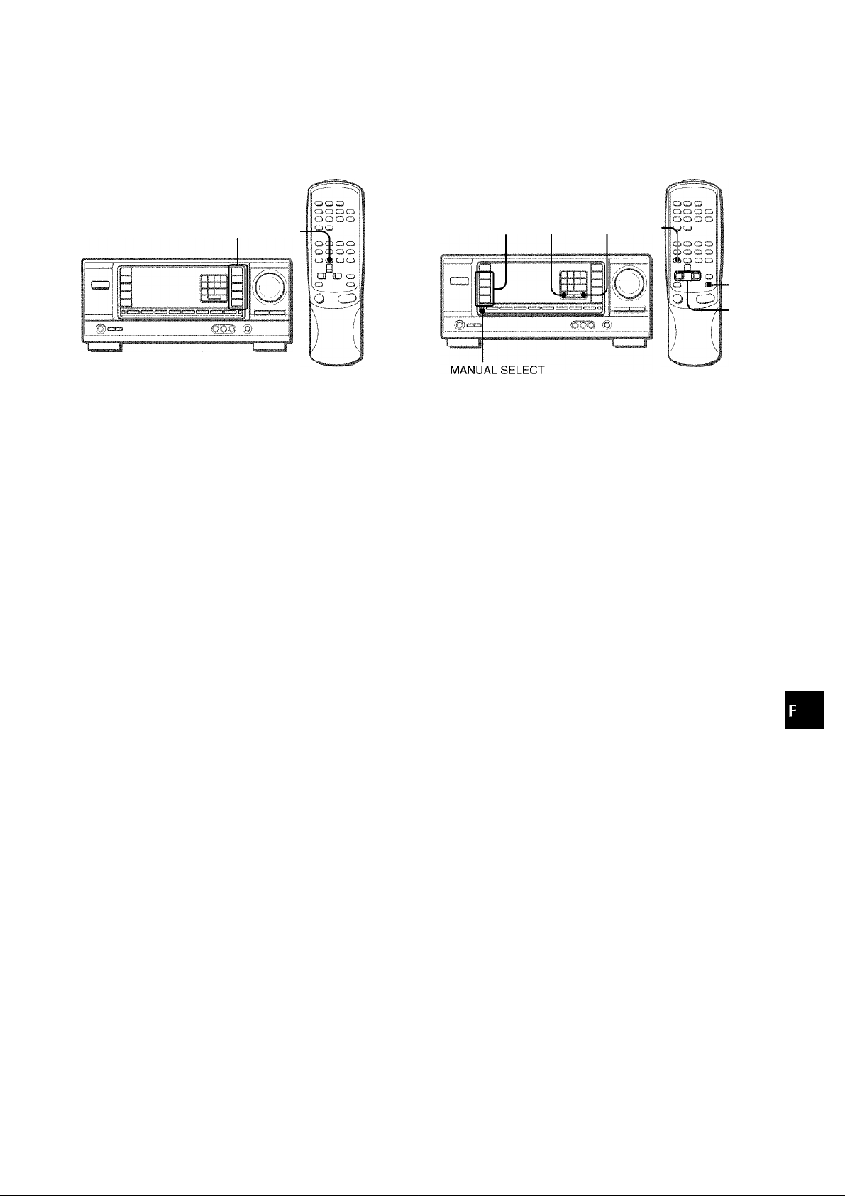
EGALISEUR GRAPHIQUE ELECTRONIQUE
GEQ GEQ
L’ampli-tuner présente les cinq modes d’égalisation suivants.
ROCK; Son puissant avec accentuation des aigus et des graves
POP: Présence améliorée des voix et des médiums
JAZZ: Accentuation des basses fréquences pour la musique de
type jazz
CLASSIC: Son plus riche avec des graves lourds et des aigus
fins
BGM: Son calme avec graves et aigus supprimés
Appuyez sur une des touches GEQ (égaliseur graphique).
Le nom du mode sélectionné apparaît sur l'afficheur pendant
deux secondes et le mode sélectionné sur le côté droit de
l’afficheur est entre parenthèses.
PROCESSEUR D’AMBIANCE
DSP DOWNV UPA dsp
MANUAL
SELECT
UP^,
DOWN<|
Les circuits du processeur d’ambiance (DSP) peuvent recréer
l’effet de sons réfléchis par les murs et les plafonds, pour simuler
la présence d’un environnement particulier. Il y a quatre modes
d’ambiance avec les modes d’égalisation correspondants. Les
modes d’égalisation sont automatiquement sélectionnés et
peuvent être activés ou désactivés selon vos goûts.
Appuyez sur une des touches DSP (DANCE, LIVE,
HALL ou ARENA).
Le nom de mode sélectionné apparaît sur l’afficheur pendant
deux secondes, puis le mode DSP et le mode GEQ
correspondant restent allumés sur l’afficheur.
O
(/)
Mode sélectionné-
CAîïCt;
LIVE
HALL
I ! i
Ì / \
i i
/ /
CROCK) I
..
FDP
JAZZ
CLASSIC
BGM
Pour annuler le mode sélectionné
Appuyez une nouvelle fois sur la touche. “GEQ oFF” apparaît
sur l’afficheur.
Pour sélectionner le mode avec la télécommande
Appuyez de façon répétée sur la touche GEQ jusqu’à ce que le
mode d’égalisation souhaité apparaisse.
CQANCEj
..
HALL
Mode DSP
-sélectionné
Mode GEQ
correspondant
[ROCK) J
ilMiii
JAZZ
CiASSIC
BGM
Quand la source de musique est monophonique
Sélectionnez LIVE pour simuler un effet stéréo. Quand vous
sélectionnez DANCE ou HALL, aucun son n’est fourni par les
enceintes surround.
Pour annuler le mode sélectionné
Appuyez une nouvelle fois sur la touche sélectionnée. “DSP oFF’’
apparaît sur l’afficheur. Même si vous annulez le mode DSP
sélectionné, le mode GEQ correspondant ou sélectionné reste
actif. Quand le processeur d’ambiance est hors service, aucun
son n’est fourni par les enceintes surround.
Pour sélectionner le mode avec la télécommande
Appuyez de façon répétée sur la touche DSP jusqu'à ce que le
mode DSP souhaité soit affiché.
Pour ajuster le volume des enceintes surround
Appuyez une fois sur MANUAL SELECT. “SUR” est affiché
pendant quatre secondes. Appuyez sur UPA ou DOWNT quand
“SUR” est affiché.
Notez que le niveau des enceintes surround en mode Dolby Pro
Logic change aussi (voir page 13).
SüDIÎO
Le DSP est automatiquement annulé quand vous mettez le
DOLBY PRO LOGIC en service.
FRANÇAIS 8
Page 42

OPERATIONS DE BASE
SELECTION D'UNE SOURCE
AUDIO OU VIDEO
1 Sélectionnez la source de programme.
Appuyez sur une des touches FUNCTION ou la touche TAPE
MONITOR.
Pour écouter ou regarder Appuyez sur la touche
une cassette TAPE MONITOR
la radio
un disque analogique PHONO
la télévision, etc.
un disque compact CD
une vidéo (magnétoscope ou LD)
MD VIDEO 2“>
Pour sélectionner AUX/TV, ou VIDEO 2/LD/MD, voir “Pour
changer le nom affiché pour la touche AUX/TV et la touche
VIDEO 2 dans “AVANT DE COMMENCER” (voir page 6).
TUNER
AUX/TV“>
VIDEO 1, VIDEO2=), VIDEOS
ENREGISTREMENT D’UNE SOURCE AUDIO
1 Sélectionnez la source de programme qui doit
être enregistrée.
Appuyez sur une des touches FUNCTION.
2 Mettez la platine à cassette ou l’enregistreur MD
en mode d’enregistrement.
3 Démarrez la source de programme sélectionnée.
Pour contrôler le son enregistré pendant l’enregistrement
(quand la platine à cassette raccordée a trois têtes)
Appuyez sur la touche TAPE MONITOR. “TAPE ON” apparaît
sur l’afficheur pendant quatre secondes, puis le nom de la source
sélectionnée à l’étape 1 réapparaît. Pour cesser de contrôler le
son, appuyez une nouvelle fols sur la touche pour que "TAPE
oFF” apparaisse.
REMARQUE
Quand vous utilisez un tourne-disque avec amplificateur
égaiiseur intégré, réglez l’interrupteur de i’amplificateurégaiiseur
sur arràt. Reportez-vous au mode d’emploi de la platine tournedisque pour les détails.
2 Démarrez la source de programme sélectionnée. 3 Réglez le son.
A propos de la source vidéo fournie au moniteur ou téiéviseur
Source vidéo sélectionnée
ROCK
eÉÜi
BQM
a
POP
' '
LIVE :
HALL ; . ,
ARENA
V1: VIDEO 1, V2: VIDEO 2, V3: VIDEO 3
La source vidéo séiectionnée est indiquée sur l’afficheur et le
signal vidéo transmis par la prise MONITOR VIDEO OUT
apparaît sur le téléviseur.
........
; ;
i/
REMARQUE
Le son contrôlé avec le système BBE n’a aucun effet sur
l’enregistrement (voir page 7).
9 FRANÇAIS
Page 43

RECEPTION RADIO
ACCORD MANUEL
MONO
TUNER
POWER
Appuyez de façon répétée sur la touche TUNER
pour sélectionner la gamme souhaitée.
FM
-------
►AM-i
Si VOUS appuyez sur la touche TUNER quand l’ampli-tuner
est éteint, il se met sous tension.
Appuyez sur la touche UPA ou DOWNT pour
sélectionner une station.
A chaque pression sur la touche, la fréquence change.
Quand vous recevez une station, “TUNE” est affiché pendant
deux secondes. Pendant la réception stéréo FM, est
affiché.
ACCORD DIRECT
“Touches
numériques
Si vous connaissez ia fréquence de la station souhaitée, vous
pouvez l’accorder directement.
1 Appuyez sur la touche TUNER pour sélectionner
une gamme.
2 Appuyez sur ia touche TUNER et maintenez-la
enfoncée jusqu’à ce que clignote sur
l’afficheur (Mode d’accord direct).
iiilll
/ îi/; i ;■ i
: I I -ifi/ /
,y
Si
S'
DANCE
LIVE
•A..
ARENA
/ I
! i
I i\ i i
I i \i i
ROCK
POP
JAZZ
CLASSIC
BGM
Pour rechercher rapidement une station (recherche automatique)
Appuyez en continu sur la touche UPA ou DOWNT jusqu’à ce
que la recherche commence. Quand une station est accordée,
la recherche s’arrête.
Pour arrêter la recherche automatique, appuyez sur la touche
UPA ou DOWNT.
• La recherche automatique peut ne pas s’arrêter sur les stations
dont le signal est trop faible.
Quand une émission FM stéréo est parasitée
Appuyez sur la touche MONO TUNER de la télécommande pour
que “MONO” apparaisse sur l’afficheur.
Le bruit est réduit, mais la réception est monophonique,
MONO
IMMI
■ooa
mi
ROCK
POP
.;azz
CLASSIC
BGM
LIVE
HALL
¡\/i
! i
1. i I I
Pour rétablir la réception stéréo, appuyez sur la touche pour
que “MONO” disparaisse.
3 Appuyez sur les touches numériques
appropriées pour accorder la station souhaitée.
Par exemple:
Pour faire l’accord sur 106,50 MHz, appuyez sur les touches
1,0, 6, 5 et 0.
Pour faire l’accord sur 95,2 MHz, appuyez sur les touches 9,
5, 2 et 0.
Pour annuler le mode d’accord direct
Appuyez sur la touche UPA ou DOWNT.
Quand vous utilisez ia téiécommande
Effectuez les étapes 1 et 2 ci-dessus puis appuyez sur les
touches numériques de la télécommande pour accorder la station
souhaitée.
REMARQUE
' Quand vous entrez une fréquence hors de la plage d’accord,
la valeur clignote sur l’afficheur pendant deux secondes puis
s’éteint. Vérifiez la fréquence et refaites l’opération 3
correctement.
‘ Si vous entrez une fréquence non couverte par l’intervalle
d’accord, la valeur est automatiquement arrondie au chiffre
inférieur ou supérieur le plus proche.
Pour changer i’intervaiie d’accord AM
Le réglage par défaut de l’intervalle d’accord AM est de 10 kHz.
Si vous utilisez cet ampli-tuner dans un pays où l’attribution des
fréquences est de 9 kHz, changez l’intervalle d’accord.
Tout en tenant la touche TUNER enfoncée, appuyez
immédiatement sur l’interrupteur POWER. Notez que l’amplituner passe au mode d’accord direct si vous appuyez pendant
environ deux secondes sur la touche TUNER.
Pour revenir à l’intervalle initial, refaites les mêmes opérations.
FRANÇAIS 10
Page 44

PREREGLAGE DES STATIONS
L’ampli-tuner peut mémoriser en tout 32 stations. Quand une
station est mémorisée, un numéro de préréglage est affecté à
cette station. Utilisez le numéro de préréglage pour accorder
directement la station préréglée.
1 Appuyez sur la touche TUNER pour sélectionner
la gamme et sur la touche UPA ou DOWNT pour
sélectionner une station. Vous pouvez aussi
utiliser l’accord direct.
ACCORD DES STATIONS PREREGLEES
1 Appuyez sur la touche TUNER pour sélectionner
une gamme.
2 Appuyez sur les touches numériques pour
sélectionner une station préréglée.
Par exemple:
Pour sélectionner le numéro de préréglage 25, appuyez sur
2 et 5.
Pour sélectionner le numéro de préréglage 7, appuyez sur 0
et 7.
Pour supprimer une station préréglée
Sélectionnez le numéro de préréglage de la station que vous
voulez supprimer. Appuyez ensuite sur la touche SET puis, dans
les quatre secondes, une nouvelle fois sur la touche SET.
Les numéros de préréglage de toutes les stations de la gamme,
supérieurs au numéro annulé diminuent d’une unité.
Quand vous utilisez la télécommande
Appuyez sur la touche TUNER pour sélectionner la gamme et
sur les touches numériques pour sélectionner une station
préréglée.
2 Appuyez sur la touche SET pour mémoriser la
station.
Un numéro est affecté à chaque station mémorisée, à partir
de 1 dans l’ordre consécutif pour chaque gamme.
Fréquence
___^__
ROCK
POP
’ '
i
Numéro de préréglage
; i :
I
JAZZ
CtASSIC
3M
3 Refaites ies opérations 1 et 2.
Il n’est pas possible de prérégler une nouvelle station si 32
stations sont déjà mémorisées pour toutes les gammes.
REMARQUE
Quand vous changez l’intervalle d’accord AM, toutes les stations
préréglées sont supprimées. Vous devez les prérégler une
nouvelle fois.
11
FRANÇAIS
Page 45

DOLBY PRO LOGIC
Le Dolby Pro Logic combiné avec des enceintes surround et
centrale (standard) permettent de bénéficier d’un véritable son
de cinéma domestique. Quand vous reproduisez des disques
laser ou des cassettes vidéo qui ont été spéciaiement enregistrés
en Dolby Surround , un son d’un réalisme étonnant enveloppe
l’auditeur et assure un divertissement audio/vidéo d’un nouveau
genre.
Le réglage indépendant des quatre canaux permet à l’auditeur
de bénéficier d’un son tel que l’on peut en faire l’expérience au
cinéma. Les voix sont reproduites par le champ sonore avant et
central, tandis que l’ambiance, par exemple bruits de voitures
ou de la foule, enveloppe de toute part et recrée une atmosphère
incroyablement réaliste. Veuillez lire attentivement ce qui suit
pour “accorder” la sortie du système en fonction des
caractéristiques de votre salle d’écoute.
Vérifiez ies points suivants:
• Avant d’utiliser le DOLBY PRO LOGIC, ajustez
correctement la balance du niveau sonore des enceintes
(voir page 13).
• Assurez-vous que les enceintes ont été raccordées et installées
correctement (voir pages 3 et 4).
• Assurez-vous que le téléviseur et l’appareil vidéo sont raccordés
correctement (voir page 3).
• Assurez-vous que le disque laser ou la cassette vidéo, etc.
porte le logo nniaxBYSURROuirol .
POUR SELECTIONNER UN MODE DOLBY
PRO LOGIC
Appuyez de façon répétée sur la touche DOLBY
PRO LOGIC pour sélectionner le mode approprié.
Quand vous sélectionnez le mode DOLBY PRO LOGIC ou
3CH LOGIC, l’indicateur s’allume et le nom du mode
sélectionné défile sur l’afficheur. A chaque pression sur la
touche, le mode change de la façon suivante.
ROCK
POP
/ î i
..U LJ L.
..Ü
Í /
r Г\
.¡A//
CLASSIC
BGM
Oü
i§
zo
O?
UICQ
SELECTION DU DOLBY PRO
LOGIC
Le mode Dolby Pro Logic optimal dépend du type et de
l’emplacement des enceintes. Il est conseillé d’utiliser les
enceintes optionnelles Aiwa pour tous les canaux, par exemple,
c’est-à-dire les SX-R1000 comme enceintes surround, la SXC1000 comme enceinte centrale et les SX-AV1000 comme
enceintes avant. Sélectionnez le mode Dolby Pro Logic en
fonction de la configuration de vos enceintes.
Mode conseillé
Enceinte centrale
Grande dimension
Enceintes surround
(enceintes arrière)
Sans enceintes
surround
Mode PHANTOM: Sélectionnez ce mode si vous ne raccordez
pas d’enceinte centrale. Les signaux du canal central sont
redistribués sur les enceintes avant gauche et droite.
Mode 3CH LOGIC: Sélectionnez ce mode si vous ne raccordez
pas d’enceintes surround.
DOLBY PRO
LOGIC-WIDE
ЗСН LOGIC
WIDE
Petite dimensionSans enceinte
DOLBY PRO
LOGIC-NORMAL
3CH LOGICNORMAL
PHANTOM
-
DOLBY PRO LOGIC
c
DOLBY PRO LOGIC oFF (annulation)
----
► 3CH LOGIC
2 Appuyez une nouvelle fois sur la touche DOLBY
PRO LOGIC et tenez la touche enfoncée jusqu’à
ce que le mode d’enceinte centrale que vous
voulez sélectionner apparaisse.
Quand vous sélectionnez le mode DOLEiY PRO LOGIC à l’étape 1 :
“NORMAL’, “WIDE” et “PHANTOM” apparaissent tour à tour
sur l’afficheur.
Quand vous sélectionnez le mode 3CH LOGIC à l’étape 1 :
“NORMAL’ et “WIDE” apparaissent tour à tour sur l’afficheur.
REMARQUE
• Avec certaines sources et dans certaines conditions d’écoute,
vous n'obtiendrez pas l’effet surround escompté même si le
DOLBY PRO LOGIC est en service.
• Vous n’obtiendrez pas un effet DOLBY PRO LOGIC parfait si
les enregistrements que vous utilisez ne portent pas le logo
nnioatBYsuRHouwol. Dans ce cas, utilisez plutôt le DSP (voir page
8).
• Le système DOLBY PRO LOGIC est automatiquement annulé
quand vous mettez le BBE ou DSP en service.
FRANÇAIS 12
Page 46

REGLAGE DE LA BALANCE DU NIVEAU DES ENCEINTES
Ajustez le niveau sonore de l’enceinte centrale
et (ou) des enceintes surround.
Quand “CEN” ou “SUR” est affiché, appuyez sur la touche
UPA ou DOWNT pour ajuster le volume des enceintes
centrale ou surround en fonction du niveau des enceintes
avant gauche et droite.
1
2
3
L’ampli-tuner intègre un générateur de signaux d’essai appelé
séquenceur de bruit pour faciliter ie réglage de la balance des
quatre canaux.
Le séquenceur fournit un signal qui passe d’un canal à l’autre,
permettant ainsi d’effectuer simplement un réglage du niveau
sonore pour obtenir le même niveau apparent pour chaque canal
à la position d’écoute.
1 Sélectionnez le mode Dolby Pro Logic en fonction
de ia configuration actuelie des enceintes.
(Voir page 12.)
2 Appuyez sur ia touche MANUAL SELECT et
tenez-ia enfoncée pendant environ deux
secondes jusqu’à ce que “L TEST” apparaisse.
ЫШ
i i
ROCK
l’OR
lA//
ClASSIi
DCM
I /
î ;; ;
/ I \
Pour ajuster la balance des enceintes gauche et droite, utilisez
la commande BALANCE quand “L TEST” ou “TEST R” est
affiché.
..
‘
____
ROCK
юза POP
.] A//
cutssic
B
BGM
4 Appuyez une nouveiie fois sur la touche MANUAL
SELECT pour arrêter le signal.
REMARQUE
Si vous changez le volume des enceintes surround du mode
DSP (voir page 8), celui des enceintes surround dans le mode
Dolby Pro Logic change aussi.
A propos des canaux
Les enceintes gauche et droite créent l’effet stéréo.
L’enceinte centraie permet d’obtenir un positionnement plus
précis du son sur un large champs sonore.
Les enceintes surround arrière augmentent la “profondeur” du
champ sonore.
Pour changer le temps de retard
Les enceintes surround reproduisent le son une fraction de
seconde après les enceintes avant. Le retard est initialement
réglé sur 20 ms (millisecondes).
Pour changer le temps de retard standard, appuyez deux ou
trois fois sur la touche MANUAL SELECT pour que “TIME” soit
affiché. Appuyez ensuite sur UPA ou DOWNV. A chaque
pression sur une de ces touches, le temps de retard change
comme suit.
15ms •
> 20ms' > 30ms
Un signal est envoyé à chaque canal dans l’ordre suivant:
Mode DOLBY PRO LOGIC NORMAL ou WIDE
!-► L TEST: (enceinte gauche) —► TEST R: (enceinte droite)
■— SUR: (enceinte surround) — CEN: (enceinte centrale)
Mode DOLBY PRO LOGIC PHANTOM
►L TEST—►TEST R—►SUR-
a
□
Mode 3CH LOGIC NORMAL ou WIDE
►L TEST—►TEST R—►CEN-
□
UOCK
POP
Pour changer le niveau sonore après avoir ajusté la
balance avec le séquenceur de bruit
Vous pouvez régler le niveau sonore des enceintes centrale et
surround pendant qu’un disque laser ou une vidéo est reproduit.
1 Appuyez une ou deux fois sur la touche MANUAL SELECT
pour sélectionner “CEN” ou “SUR” (centre ou surround).
2 Quand “CEN” ou “SUR” est affiché, appuyez sur UPA ou
DOWNT pour ajuster le volume.
13 FRANÇAIS
Page 47

MINUTERIE
REGLAGE DE LA MINUTERIE
GENERAlTES
D’ARRET
L’ampli-tuner peut être automatiquement mis hors tension à une
heure précise.
Utiiisez la télécommande.
1 Appuyez sur la touche SLEEP.
SDIN ET ENTRETIEN
Un entretien occasionnel de i’ampli-tuner est indispensable pour
garantir des performances optimales.
Pour nettoyer le coffret
Utilisez un chiffon doux et sec.
Si la surface est extrêmement sale, utilisez un chiffon légèrement
imprégné d’une soiution détergente neutre. Ne pas utiliser de
solvants puissants, tels que l’alcool, la benzine et du diluant, car
ils pourraient abîmer la finition.
i i I i
" i /■■■' r
/ ;
2 En l’espace de quatre secondes, désignez le
temps de fonctionnement de l’ampli-tuner en
appuyant sur la touche UP>M ou D0WNI4^.
A chaque pression sur la touche, le temps change par
incréments de 5 minutes de 5 à 240 minutes.
Temps désigné
/ / / I
■ i i " i "
Pour vérifier le temps restant jusqu’à la mise hors tension
Appuyez une fois sur la touche SLEEP. Le temps restant est
affiché pendant quatre secondes.
Pour arrêter la minuterie
Appuyez deux fois sur la touche SLEEP pour que “SLEEP”
disparaisse de l’afficheur.
I }
FRANÇAIS 14
Page 48

SPECIFICATIONS
Section Tuner FM
Plage d’accord 87,5 MHz à 108 MHz
Sensibilité utilisable 13,2 dBf
(1HF)
Bornes d’antenne 75 ohms (asymétrique)
Section Tuner AM
Plage d’accord
Sensibilité utilisable
Antenne
Section Amplificateur
Puissance de sortie
Distorsion harmonique
totale
Entrées
530 kHz à 1710 kHz (intervalle de 10
kHz), 531 kHz à 1602 kHz (intervalle
de 9 kHz)
350 |jV/m
Antenne cadre
[Mode stéréo]
Avant
75 watts par canal, minimum RMS à 4
O 8 ohms, de 40 Hz à 20 kHz, avec
moins de 0,8 % de distorsion
harmonique totale
[Mode Dolby Pro Logic]
Avant
70 watts par canal, minimum RMS à 4
O 8 ohms, de 40 Hz à 20 kHz, avec
moins de 0,9 % de distorsion
harmonique totale
Arrière (Surround)
35 watts par canal, minimum RMS à 8
ohms, 1 kHz, avec moins de 0,9 % de
distorsion harmonique totale
Centre
70 watts, minimum RMS à 4 o 8
ohms, 1 kHz, avec moins de 0,9 % de
distorsion harmonique totale
0,07 % (50 W, 1 kHz, 8 ohms.
Enceintes avant)
AUDIO IN
PHONO: 2,8 mV (50 kohms)
CD: 370 mV (50 kohms)
TAPE MONITOR: 200 mV (25
kohms)
VIDEO 1, VIDEO 2/LD/MD,
VIDEO 3, AUX/TV: 370 mV (50
kohms)
VIDEO IN: 1 Vc-c (75 ohms)
Sorties
Coupure du son
AUDIO OUT (REC OUT): 230 mV (2
kohms)
VIDEO OUT (MONITOR): 1 Vc-c (75
ohms)
SUPER WOOFER: 3,1 V
FRONT SPEAKERS IMP: 8i2/4£2
au choix (enceintes avant A et B):
avec SPEAKER IMPEDANCE
SELECTOR réglé sur 4£2, accepte
des enceintes de 4 ohms
avec SPEAKER IMPEDANCE
SELECTOR réglé sur 80, accepte
des enceintes de 8 ohms ou plus
SURROUND SPEAKERS IMP: 80
(enceintes surround): accepte des
enceintes de 8 ohms ou plus
CENTER SPEAKER IMP: 80/40 au
choix
avec SPEAKER IMPEDANCE
SELECTOR réglé sur 40, accepte
des enceintes de 4 ohms,
avec SPEAKER IMPEDANCE
SELECTOR réglé sur 80, accepte
des enceintes de 8 ohms ou plus.
PHONES üack stéréo): accepte un
casque de 32 ohms ou plus
-20 dB
Généralités
Alimentation
Consommation
Dimensions (l/h/p)
Poids
La conception et les spécifications peuvent être modifiées sans
préavis.
uuu SYSTEM
Le mot “BBE” et le logo “BBE SYSTEM” sont des marques de
BBE Sound, Inc.
Sous licence de BBE Sound, Inc.
DOLBY PRO LOGIC
Fabriqué sous licence de Dolby Laboratories Licensing
Corporation.
“DOLBY”, le symbole du double D □□ et “PRO LOGIC” sont des
marques de fabrique de Dolby Laboratories Licensing
Corporation.
Secteur 120 V, 60 Hz
160 W
360 X 153,5 X 335 mm (14V4 x 6Vs x
13V4 po.)
8,5kg(18li.12on.)
15 FRANÇAIS
Page 49

EN CAS DE PANNE
NOMENCLATURE
Si l’ampli-tuner ne fonctionne pas comme décrit dans le mode
d’emploi, vérifiez les points suivants.
GENERAL
Aucun son.
• Est-ce que le cordon secteur est raccordé correctement?
• Est-ce qu’un raccordement n’est pas exact? (-* page 3)
• Est-ce qu’il y a un court-circuit au niveau des bornes
d’enceintes?
Débranchez le cordon secteur, puis raccordez correctement
l’enceinte.
• Est-ce que vous avez appuyé sur une mauvaise touche?
• Est-ce que les touches FRONT SPEAKERS A et B sont réglées
correctement? (-► page 6)
Son émis par une enceinte seuiement.
• Est-ce que le réglage BALANCE est correct ?
• Est-ce que l’autre enceinte est débranchée ?
Le volume sonore est considérablement réduit.
• Est-ce que vous avez appuyé sur la touche MUTING?
Affichage erroné ou dysfonctionnement.
-► Réinitialisez l’ampli-tuner comme indiqué ci-dessous.
SECTION TUNER
Parasites électrostatiques constants.
• Est-ce que l’antenne est correctement raccordée? (-» page 5)
• Est-ce que le signal FM est faible?
-♦ Raccordez une antenne extérieure.
La réception contient des interférences ou le son
présente de la distorsion.
• Est-ce que la chaîne capte du bruit ou est-ce qu’il y a des
interférences par trajets multiples?
-► Changez l’orientation de l’antenne.
-► Eloignez îampli-tuner des autres appareils électriques.
Les instructions concernant chaque touche de l’ampli-tuner ou [3
la télécommande se trouvent aux pages indiquées ci-dessous. t
-.S ;
Commandes Pages
AUX/TV
BALANCE 7, 13
BBE 7
CD 6, 9
CLOCK
DOLBY PRO LOGIC
DOWN ▼ (◄)
DSP 8
FRONT SPEAKERS A, B
GEO
MANUAL SELECT (TEST)
MONO TUNER
MUTING, MUTE 7
PHONES
PHONO
POWER
SET
SLEEP
SPEAKER IMPEDANCE
SELECTOR
TAPE MONITOR
T-BASS
TUNER, BAND DIRECT
TUNER PRESET
UP A(^)
VIDEO 1
VIDEO 2, LD/MD
VIDEO 3
VOLUME (V, /\)
6, 9
6
12, 13
6, 8, 10, 11, 13, 14
6
8
8, 13
10
6
6, 9
6, 10
6, 11
14
4
6, 9
7
6, 9, 10, 11
6
6, 8, 10, 11, 13, 14
6, 9
6, 9
6, 9
7
. 1E11
' ©1
<
Z
JJ
Pour réinitialiser l’ampli-tuner
Si l’affichage ou le fonctionnement n’est pas normal, réinitialisez
l’ampli-tuner de la manière suivante.
1 Appuyez sur l’interrupteur POWER pour mettre l’ampli-tuner
hors tension.
2 Appuyez sur l’interrupteur POWER tout en tenant la touche
SET enfoncée. Tous les préréglages sont effacés.
Si vous ne pouvez pas mettre l’ampli-tuner hors tension à l’étape
1 parce qu’il ne fonctionne pas normalement, réinitialisez-le en
débranchant le cordon secteur et refaites l’opération 2.
FRANÇAIS 16
Page 50

Page 51

Page 52

AIWA CO.,LTD.
For assistance and information call toll free 1-800-BUY-AIWA (United States and Puerto Rico)
Printed in Malaysia
 Loading...