

Page 1
8Z-AR2-903-I 1
9908’20BCK-Y-9
I
I
I
For assistance and information
call toll free I-800=BUY-AIWA
(United States and Puerto Rico)
Page 2
!IA=AI
“CAUTION:TO REDUCE THE RISK OF
ELECTRIC SHOCK,
DO NOT REMOVE COVER (OR BACK).
NO USER-SERVICEABLE PARTS INSIDE.
REFER SERVICING TO QUALIFIED
SERVICE PERSONNEL.”
/ Model No.
I Serial No. (Lot No.)
I
Instructions and on the unit should be strictly followed, as well
as the safety suggestions below.
Installation
1
2
3
4
5
6
7
Water and moisture — Do not use this unit near water, such
as near a bathtub, washbowl, swimming pool, or the like.
Heat — Do not use this unit near heat sources, including
heating vents, stoves, or other appliances that generate heat.
It also should not be placed in temperatures less than 5°C
(41“F) or higher than 35°C (95°F).
Mounting surface — Place the unit on a flat, even surface.
Ventilation — The unit should be situated with adequate
space around it so that proper heat ventilation is assured.
Allow 10 cm (4 in.) clearance from the rear and the top of the
unit, and 5 cm (2 in.) from each side.
- Do not place the unit on a bed, rug, or similar surface that
may block the ventilation openings.
- Do not install the unit in a bookcase, cabinet, or airtight
rack where ventilation may be impeded.
Objects and liquid entry — Take care that objects or liquids
do not get inside the unit through the ventilation openings.
Carts and stands — When placed or
mounted on a stand or cart, the unit
should be moved with care.
Quick stops, excessive force, and
uneven surfaces may cause the unit or
m
3
AL*
cart to overturn or fall.
Wall or ceiling mounting — The unit should not be mounted
on a wall or ceiling, unless specified in the Operating
Instructions.
Electric Power
1
2
3
4
Owner’s record
For your convenience, record the model number and serial
number (you will find them on the rear of your unit) in the space
provided below. Please refer to them when you contact your
Aiwa dealer in case of difficulty.
5
I AV-DV75 I I
Power sources — Connect this unit only to power sources
specified in the Operating Instructions, and as marked on
the unit.
Polarization — As a safety feature, some units are equipped
with polarized AC power plugs which can only be inserted
one way into a power outlet. If it is difficult or impossible to
inserf the AC power plug into an outlet, turn the plug over
and try again. If it is not still inserted easily into the outlet,
please call a qualified service technician to service or replace
the outlet. To avoid defeating the safety feature of the
polarized plug, do not force it into a power outlet.
AC power cord
- When disconnecting the AC power cord, pull it out by the
AC power plug. Do not pull the cord itself.
- Never handle the AC power plug with wet hands, as this
could result in fire or shock.
- Power cords should be firmly secured to avoid being
severely bent, pinched, or walked upon, Pay particular
attention to the cord from the unit to the power socket.
- Avoid overloading AC power plugs and extension cords
beyond their capacity, as this could result in fire or shock.
Extension cord — To help prevent electric shock, do not
use a polarized AC power plug with an extension cord,
receptacle, or other outlet unless the polarized plug can be
completely inserted to prevent exposure of the blades of the
plug.
When not in use — Unplug the AC power cord from the AC
power outlet if the unit will not be used for several months or
more. When the cord is plugged in, a small amount of current
continues to flow to the unit, even when the power is turned
off.
1 ENGLISH
Page 3
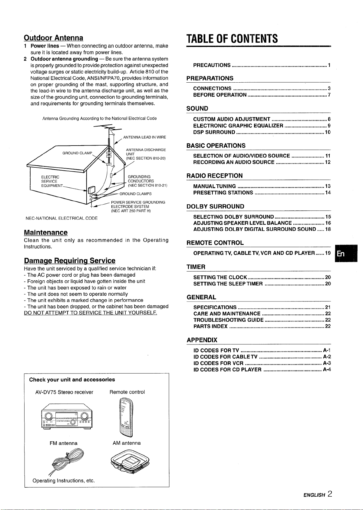
Outdoor Antenna
TABLE OF CONTENTS
1 Power lines — When connecting an outdoor antenna, make
sure it is located away from power lines.
2 Outdoor antenna grounding — Be sure the antenna system
is properly grounded to provide protection against unexpected
voltage surges or static electricity build-up. Article 810 of the
National Electrical Code, ANS1/NFPA70, provides information
on proper grounding of the mast, supporting structure, and
the lead-in wire to the antenna discharge unit, as well as the
size of the grounding unit, connection to grounding terminals,
and requirements for grounding terminals themselves.
AntennaGroundingAccordingtothe NationalElectricalCode
)
(NEC ART 250 PART H)
NEC-NA-FIONALELECTRICALCODE
Maintenance
Clean the unit only as recommended in the Operating
Instructions.
Damaue Requiring Service
Have the unit serviced by a qualified service technician if:
- The AC power cord or plug has been damaged
- Foreign objects or liquid have gotten inside the unit
- The unit has been exposed to rain or water
- The unit does not seem to operate normally
- The unit exhibits a marked change in performance
- The unit has been dropped, or the cabinet has been damaged
DO NO1”ATTEMPT TO SERVICE THE UNIT YOURSELF.
Checlk your unit and accessories
AV-DV75 Stereo receiver
Remote control
FM antenna
AM antenna
Operating Instructions, etc.
PRECAUTIONS ................................................................ 1
PREPARATION!;
CONNECTIONS ................................................................ 3
BEFORE OPERATION .................................................. .....
7
SOUND
CUSTOM AUDIO ADJUSTMENT ................................. ... 8
ELECTRONIC GRAPHIC EQUALIZER ............................. 91
DSP SURROUND ............................................................ 10
BASIC OPERATIONS
SELECTION OF AUDIO/VIDEO SOURCE ...................... 11
RECORDING AN AUDIO SOURCE ..................(............ 12
RADIO RECEPTION
MANUALTUNING ...........................................mm.r..........!!...
13
PRESETTING STATIONS .............................................. 141
DOLBY SURROUND
SELECTING DOLBY SURROUND ................................... 15
ADJUSTING SPEAKER LEVEL BALANCE
...................... 16
ADJUSTING DC)LBY DIGITAL SURROUND SCNJND.....18
REMOTE CONTROL
OPERATING TV, CABLE TV,VCR AND CD PLAYER .....19
“m
TIMER
SETTING THE CLOCK
.....m...m..............m...........=..l.............Q2cl
SETTING THE SLEEP TIMER
..........................................2C)
GENERAL
SPECIFICATIONS
.............................................................2l
CARE AND MAINTENANCE .............................. ..............21!
TROUBLESHOOTING GUIDE ............................. .............22!
PARTS INDEX .....................m...m..........................ll..............22!
APPENDIX
ID CODES FOR TV ........................................................ A-1
ID CODES FOR CABLETV ............................... .......... A-1!
ID CODES FOR VCR .....................................,,.,,,.......1....
A-3
ID CODES FOR CD PLAYER ............................ .......... A-41
Page 4
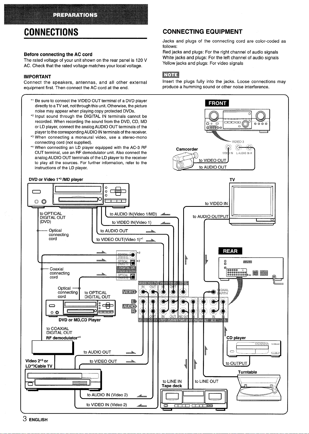
CONNECTIONS
CONNECTING EQUIPMENT
Jacks and plugs of the connecting cord are color-coded as
follows:
Before connecting the AC cord
Red jacks and plugs: For the right channel of audio signals
The rated voltage of your unit shown on the rear panel is 120 V
White jacks and plugs: For the left channel of audio signals
AC. Check that the rated voltage matches your local voltage.
Yellow jacks and plugs: For video signals
IMPORTANT
m
Connect the .smeakers, antennas, and all other external
Insert the plugs fully into the jacks. Loose connections may
equipment first. then connect the AC cord at the end.
produce a humming sound or other noise interference.
*’ Be sure to connect the VIDEO OUT terminal of a DVD player
directly to aTV set, notthrough this unit. Otherwise, the picture
-
noise may appear when playing copy protected DVDS.
*2Input sound through the DIGITAL IN terminals cannot be
Q ‘.. ””...
o
.’ Q
recorded. When recording the sound from the DVD, CD, MD
Q). D
@
000 nn o ~ooo
or LD player, connect the analog AUDIO OUT terminals of the
f3m00
.0
player tothe corresponding AUDIO INterminals of the receiver.
*3When connecting a monaural video, use a stereo-mono
connecting cord (not supplied).
VIDEO3
‘4 When connecting an LD player equipped with the AC-3 RF
OUT terminal, use an RF demodulator unit. Also connect the
analog AUDIO OUT terminals of the LD player to the receiver
to olav all the sources. For further information. refer to the -’T
,.
instructions of the LD player.
DVD or Video 1*3/MD player
MJJ4&#
to AUDIO OUT
)
Tv
o OPTICAL
31GITAL OUT
:DVD)
— Optical
connecting
cord
I I [ to AUDIO lNO/ideo I/MD) -
l{
to VIDEO lN(Video 1) A
[ to AUDIO OUT A
to VIDEO OUT(Video 1)*1 -
I
O@ical 4
I
connecting
to OPTICAL
cord
DIGITAL OUT
EiEa!Ez
DVD or MD,CD Player
I
to COAXIAL
DIGITAL OUT
RF demodulator*4
,..
@j
IN
w
k
Turntable
\
o LINE OUT
-k’{
m
3 ENGLISH
n
4
to LINE IN
Tape deck
#_
to AUI
Emm
—
J
i!
CD player
>
.==
to OUTPUT
Page 5
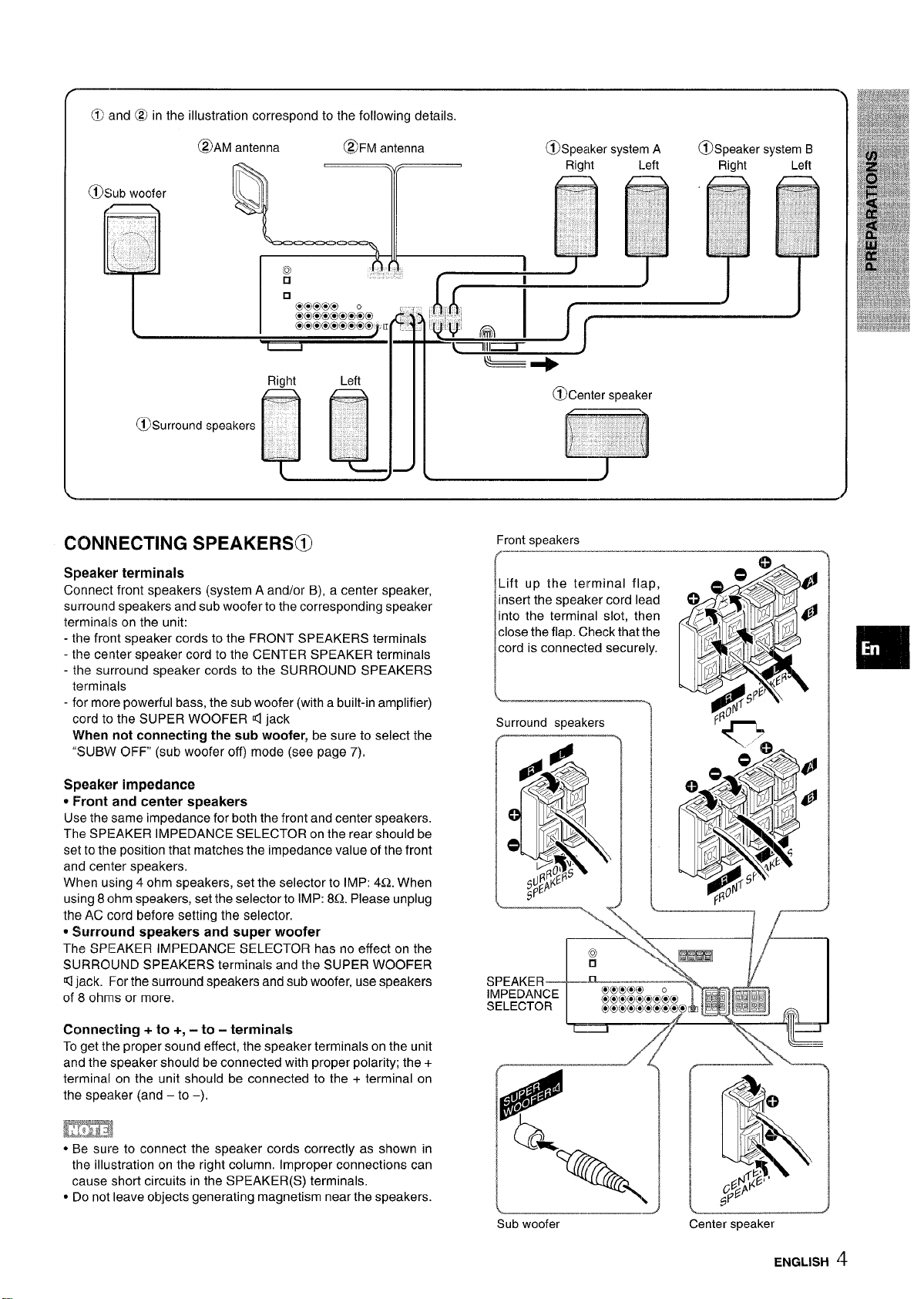
CONNECTING SPEAKERS@)
Front speakers
.
——
Speaker terminals
Connect front speakers (system A and/or B), a center speaker,
Lift up the terminal flap,
surround speakers and sub woofer to the corresponding speaker
insert the speaker cord lead
terminals on the unit:
into the terminal slot, then
- the front speaker cords to the FRONT SPEAKERS terminals
close the flap. Check that the
- the center speaker cord to the CENTER SPEAKER terminals
cord is connected securely.
- the surround speaker cords to the SURROUND SPEAKERS
terminals
I
- for more powerful bass, the sub woofer (with a built-in amplifier)
L ———.
cord to the SUPER WOOFER 4 jack
Surround speakers
When not connecting the sub woofer, be sure to select the
“SUBW OFF (sub woofer off) mode (see page 7),
Speaker’ impedance
* Front and center speakers
Use the same impedance for both the front and center speakers.
The SPEAKER IMPEDANCE SELECTOR on the rear should be
set to the position that matches the impedance value of the front
and center speakers,
When using 4 ohm speakers, set the selector to IMP: 4Q. When
using 8 ohm speakers, set the selector to IMP: 8Q. PIease unplug
the AC cord before setting the selector,
* Surround speakers and super woofer
The SPEAKER IMPEDANCE SELECTOR has no effect on the
SURROUND SPEAKERS terminals and the SUPER WOOFER
\
Kljack. For the surround speakers and sub woofer, use speakers
SPEAKER———
of 8 ohms or more.
IMPEDANCE
SELECTOR
Connecting + to +, -to - terminals
To get the proper sound effect, the speaker terminals on the unit
.\
“n
—
——————7/-----”
and the speaker should be connected with proper polarity; the +
‘@
____”_/~
terminal on the unit should be connected to the + terminal on
the speaker (and – to –),
L
H
,
●,,4
,0
fnmi
● Be sure to connect the speaker cords correctly as shown in
b
e-
the illustration on the right column. Improper connections can
cause short circuits in the SPEAKER(S) terminals.
%
c Do not leave objects generating magnetism near the speakers.
\
Sub woofer
Center speaker
ENGLISH ‘$
Page 6
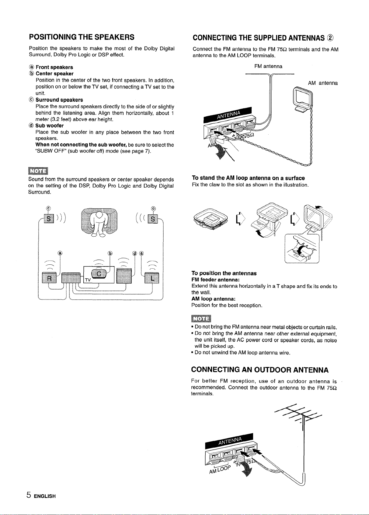
POSITIONING THE SPEAKERS
Position the speakers to make the most of the Dolby Digital
Surround, Dolby Pro Logic or DSP effect.
@ Front speakers
@ Center speaker
Position in the center of the two front speakers. In addition,
position on or below the TV set, if connecting a TV set to the
unit.
@ Surround speakers
Place the surround speakers directly to the side of or slightly
behind the listening area. Align them horizontally, about 1
meter (3.2 feet) above ear height.
@ Sub woofer
Place the sub woofer in any place between the two front
speakers.
When not connecting the sub woofer, be sure to select the
“SUBW OFF” (sub woofer off) mode (see page 7).
m
Sound from the surround speakers or center speaker depends
on the setting of the DSP, Dolby Pro Logic and Dolby Digital
Surround.
CONNECTING THE SUPPLIED ANTENNAS @
Connect the FM antenna to the FM 75Q terminals and the AM
antenna to the AM LOOP terminals.
FM antenna
Y(
AM antenna
To stand the AM loop antenna on a surface
Fix the claw to the slot as shown in the illustration.
@g
~’,
,.
.. ....... >
y.
+..
...4. :. ...
. .
,,..,.
,.:,’;;:‘
.,.
%’:
..... :
......
\
*
‘-’d
‘-’%
->
To position the antennas
FM feeder antenna:
Extend this antenna horizontally in a T shape and fix its ends to
the wall.
AM loop antenna:
Position for the best reception,
● Do not bring the FM antenna near metal objects or curtain rails,
● Do not bring the AM antenna near other external equipment,
the unit itself, the AC power cord or speaker cords,
as noise
will be picked up.
● Do not unwind the AM loop antenna wire,
CONNECTING AN OUTDOOR ANTENNA
For better FM reception, use of an outdoor antenna is
recommended. Connect the outdoor antenna to the FM 75Q
terminals.
5 ENGLISH
Page 7
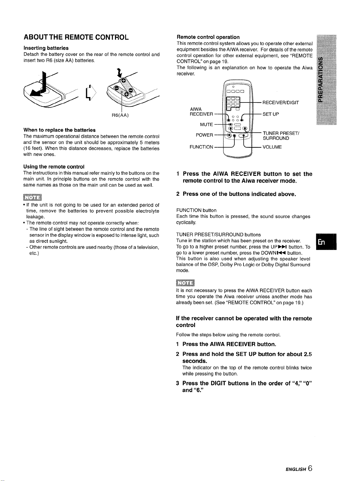
ABOIJTTHE REMOTE CONTROL
Inserting batteries
Detach the battery cover on the rear of the remote control and
insert two R6(size AA) batteries.
R6(AA)
When to replace the batteries
The maximum operational distance between the remote control
and the sensor on the unit should be approximately 5 meters
(16 feet). When this distance decreases, replace the batteries
with new ones.
Using the remote control
The instructions in this manual refer mainly to the buttons on the
main unit. In principle buttons on the remote control with the
same names as those on the main unit can be used as well.
mm
● If the unit is not going to be used for an extended period of
time, remove the batteries to prevent possible electrolyte
leakage.
● The remote control may not operate correctly when:
- The line of sight between the remote control and the remote
sensor in the display window is exposed to intense light, such
as direct sunlight.
- Other remote controls are used nearby (those of a television,
etc.)
Remote control operation
This remote control system allows you to operate other external
equipment besides the AIWA receiver. For details c~fthe remote
control operation for other external equipment, see “REMOTE
CONTROL” on page 19.
The following is an explanation on how to operate the Aiwi~
receiver,
RECEIVER/DIGIT
AIWA
RECEIVER – SET UP
MUTE –
POWER –
TUNER PRESET/
SURROUND
FUNCTION
–+J ~+ VOLUME
12Press the AIWA RECEIVER button to set
remote control to the Aiwa receiver mode.
Press one of the buttons indicated above.
the
FUNCTION button
Each time this butlton is pressed, the sound source changes
cyclically.
TUNER PRESET/SURROUND buttons
Tune in the station which has been preset on the receiver.
To go to a higher preset number, press the UP-II button. To
go to a lower preset number, press the DOWN K< button.
This button is also used when adjusting the speaker level
balance of the DSP, Dolby Pro Logic or Dolby Digital Surround
mode.
EmE!
It is not necessary to press the AIWA RECEIVER button each
time you operate the Aiwa receiver unless another mode has
already been set. (See “REMOTE CONTROL” on page 19.)
If the receiver cannot be operated with the remote
control
Follow the steps below using the remote control.
1
2
3
Press the AIWA RECEIVER button.
Press and hold the SET
UP button for about 2.5
seconds.
The indicator on the top of the remote control blinks twits
while pressing the button.
Press the DIGIT buttons in the order of “4:’ “O”
and “6.”
(’
IENGLI$H )
Page 8
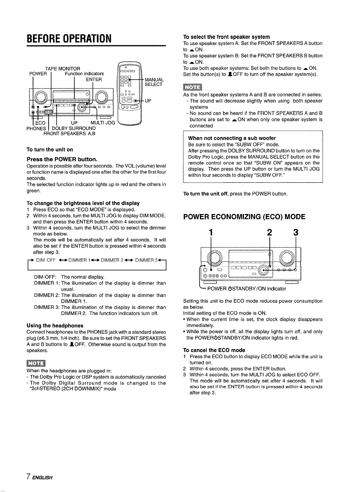
BEFORE OPERATION
TAPE MONITOR
POWER
Function indicators
I
I
ENTER
FRONT SPEAKERS A,B
To turn the unit on
Press the POWER button.
Operation is possible after four seconds. The VOL (volume) level
or function name is displayed one after the other for the first four
seconds.
The selected function indicator lights up in red and the others in
green.
To change the brightness level of the display
1 Press ECO so that “ECO MODE” is displayed.
2 Within 4 seconds, turn the MULTI JOG to display DIM MODE,
and then press the ENTER button within 4 seconds.
3 Within 4 seconds, turn the MULTI JOG to select the dimmer
mode as below.
The mode will be automatically set after 4 seconds. It will
also be set if the ENTER button is pressed within 4 seconds
after step 3.
r
DIM OFF -DIMMER 1- DIMMER2- DIMMER3
n
I
I
DIM-OFF: The normal display.
DIMMER 1: The illumination of the display is dimmer than
usual.
DIMMER 2: The illumination of the display is dimmer than
DIMMER 1.
DIMMER 3: The illumination of the display is dimmer than
DIMMER 2. The function indicators turn off.
Using the headphones
Connect headphones to the PHONES jack with a standard stereo
plug (06.3 mm, 1/4 inch). Be sure to set the FRONT SPEAKERS
A and B buttons to IOFF. Otherwise sound is output from the
speakers.
When the headphones are plugged in:
- The Dolby Pro Logic or DSP system is automatically canceled
- The Dolby Digital Surround mode is changed to the
“2chSTERE0 (2CH DOWNMIX)” mode
To select the front speaker system
To use speaker system A: Set the FRONT SPEAKERS A button
to -ON.
To use speaker system B: Set the FRONT SPEAKERS B button
to -ON.
To use both speaker systems: Set both the buttons to - ON.
Set the button(s) to 10FF to turn off the speaker system(s).
As the front speaker systems A and B are connected in series:
- The sound will decrease slightly when using both speaker
systems
- No sound can be heard if the FRONT SPEAKERS A and B
buttons are set to -ON when only one speaker system is
connected
When not connecting a sub woofer
Be sure to select the “SUBW OFF mode.
After pressing the DOLBY SURROUND button to turn on the
Dolby Pro Logic, press the MANUAL SELECT button on the
remote control once so that “SUBW ON” appears on the
display. Then press the UP button or turn the MULTI JOG
within four seconds to display “SUBW OFF.”
To turn the unit off, press the POWER button.
POWER ECONOMIZING (ECO) MODE
1
2 3
Setting this unit to the ECO mode reduces power consumption
as below.
Initial setting of the ECO mode is ON.
● When the current time is set, the clock display disappears
immediately.
● While the power is off, all the display lights turn off, and only
the POWER(!) STANDBY/ON indicator lights in red.
To cancel the ECO mode
1
2
3
Press the ECO button to display ECO MODE while the unit is
turned on.
Within 4 seconds, press the ENTER button.
Within 4 seconds, turn the MULTI JOG to select ECO OFF.
The mode will be automatically set after 4 seconds. It will
also be set if the ENTER button is pressed within
4 seconds
after step 3.
7 ENGLISH
Page 9
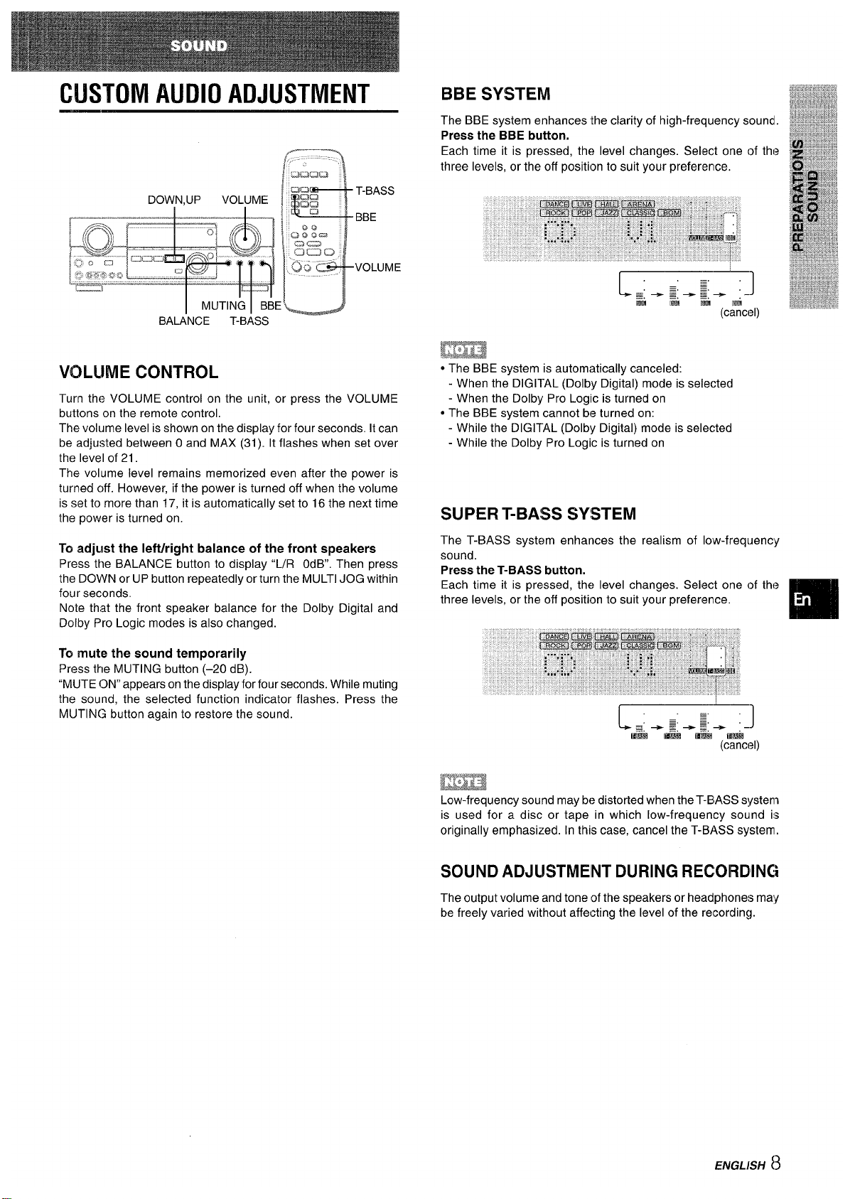
CUSTOM AUDIO ADJUSTMENT
VOLUME CONTROL
Turn the VOLUME control on the unit, or press the VOLUME
buttons on the remote control,
The volume level is shown on the display for four seconds. It can
be adjusted between Oand MAX (31). It flashes when set over
the level of 21.
The volume level remains memorized even after the power is
turned c)ff. However, if the power is turned off when the volume
is set to more than 17, it is automatically set to 16 the next time
the power is turned on.
To adjLlst the Ieftiright balance of the front speakers
Press the BALANCE button to display “L/R OdB. Then press
the DOWN or UP button repeatedly or turn the MULTI JOG within
four seconds.
Note that the front speaker balance for the Dolby Digital and
Dolby Pro Logic modes is also changed.
To mute the sound temporarily
Press the MUTING button (–20 dB).
“MUTE ON” appears on the display for four seconds. While muting
the sound, the selected function indicator flashes. Press the
MUTING button again to restore the sound.
EEm
* The BBE system is automatically canceled:
- When the DIGI1-AL (Dolby Digital) mode is selected
- When the Dolby Pro Logic is turned on
● The BBE system cannot be turned on:
- While the DIGITAL (Dolby Digital) mode is selected
- While the Dolby Pro Logic is turned on
SUPER T-BA!SS SYSTEM
The T-BASS system enhances the realism of low-frequency
sound.
Press the T-BASS button.
Each time it is pressed, the level changes. Select one of the
three levels, or the off position to suit your preference.
m
IEE!E3
Low-frequency sound may be distorted when the T-BIASSs!lstem
is used for a disc or tape in which low-frequency
sound is
originally emphasized. In this case, cancel the T-BASS system.
SOUND ADJLISTMEINT DURING RECORDING
The output volume and tone of the speakers or headphones may
be freely varied without affecting the level of the recording.
ENGLISH 8
Page 10
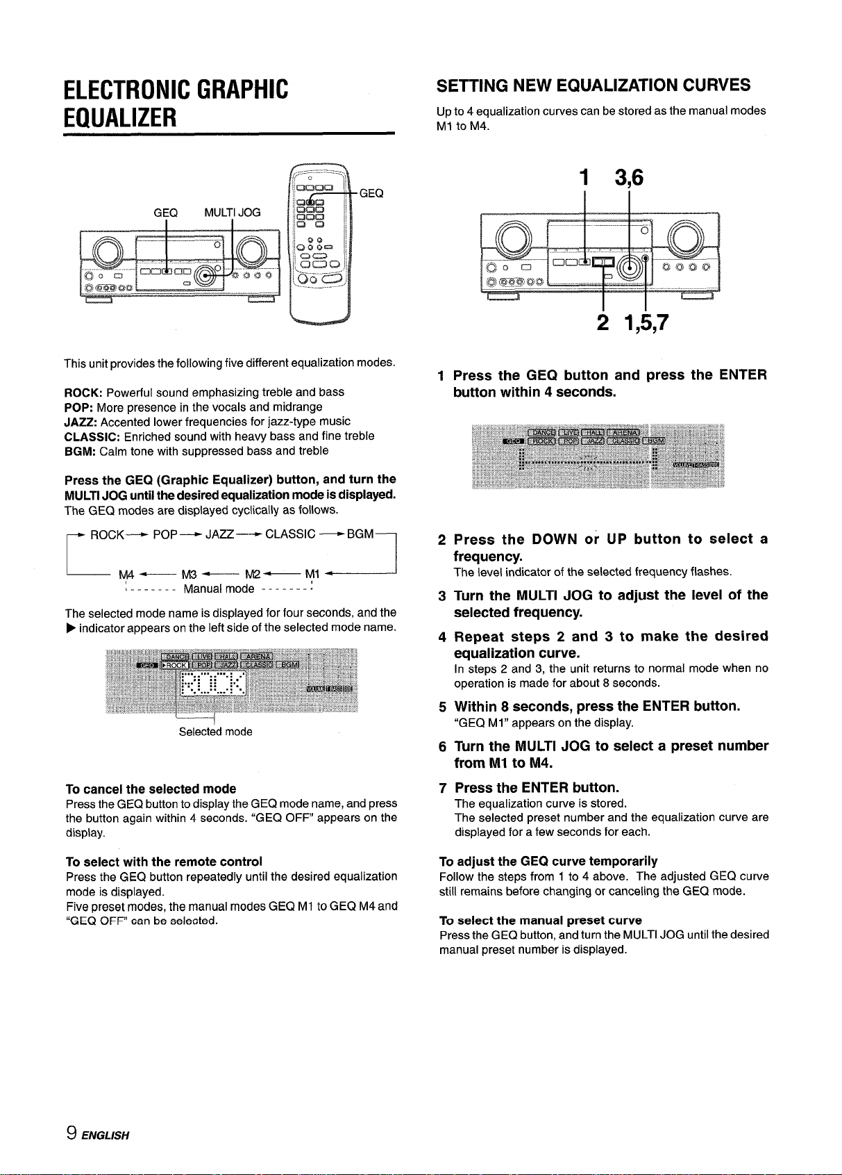
ELECTRONIC GRAPHIC
EQUALIZER
This unit provides the following five different equalization modes.
ROCK: Powerful sound emphasizing treble and bass
POP: More presence in the vocals and midrange
JAZZ:Accented lower frequencies for jazz-type music
CLASSIC: Enriched sound with heavy bass and fine treble
BGM: Calm tone with suppressed bass and treble
Press the GEQ (Graphic Equalizer) button, and turn the
MULTIJOG untilthedesiredequalizationmodeis displayed.
The GEQ modes are displayed cyclically as follows.
~ ROCK———+POP— JAZZ— CLASSIC —BGM-l
L
y4—
M3—
M2—
.,
-.._.-l
L------- Manua: mode -------:
The selected mode name is displayed for four seconds, and the
F indicator appears on the left side of the selected mode name.
I
Selected mode
To cancel the selected mode
Pressthe GEQ button to display the GE(2 mode name, and press
the button again within 4 seconds. “GEQ OFF” appears on the
display.
To select with the remote control
Press the GEQ button repeatedly until the desired equalization
mode is displayed.
Five preset modes, the manual modes GEQ Ml to GEQ M4 and
“GEQ OFF” can be selected.
SETTING NEW EQUALIZATION CURVES
Up to 4 equalization curves can be stored as the manual modes
Ml to M4.
1 3,6
1
2
3
4
5
6
7
2 1,5,7
Press the GEQ button and press the ENTER
button within 4 seconds.
Press the DOWN or UP button to select a
frequency.
The level indicator of the selected frequency flashes.
Turn the MULTI JOG to adjust the level of the
selected frequency.
Repeat steps 2 and 3 to make the desired
equalization curve.
In steps 2 and 3, the unit returns to normal mode when no
operation is made for about 8 seconds.
Within 8 seconds, press the ENTER button.
“GEQ Ml” appears on the display.
Turn the MULTI JOG to select a preset number
from Ml to M4.
Press the ENTER button.
The equalization curve is stored.
The selected preset number and the equalization curve are
displayed for a few seconds for each.
To
adjust the GEQ curve temporarily
Follow the steps from 1 to 4 above. The adjusted GEQ curve
still remains before changing or canceling the GEQ mode.
To select the manual preset curve
Press the GEQ button, and turn the MULTI JOG until the desired
manual preset number is displayed.
9 ENGLISH
Page 11
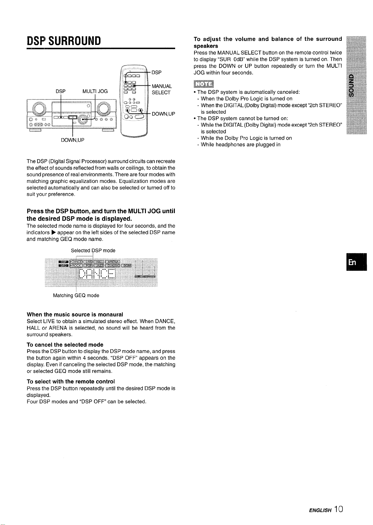
DSPWURROUND
To adjust the volume and balance of the surround
W~&$$J%&
,~y%q~~,.~$
speakers
iWa%%&
g&~**
Press the MANUAIL SELECT button on the remote controll twice
&l&*g#*&&@
‘ma%2P&%!
DOWN,UP
DSP
MANUAL
SELECT
DOWN,UP
to display “SUR OdB while the DSP system is turned on Then
press the DOWN or UP button repeatedly or turn the MUL1”I
JOG within four seconds.
m
● The DSP system is automatically canceled:
- When the Dolby Pro Logic is turned on
- When the DIGITAL (Dolby Digital) mode except “2ch STEREC)”
is selected
● The DSP system cannot be turned on:
- While the DIGITAL (Dolby Digital) mode except “2ch STEREC)”
is selected
- While the Dolby Pro Logic is turned on
- While headphones are plugged in
The DSP (Digital Signal Processor) surround circuits can recreate
the effect of sounds reflected from walls or ceilings, to obtain the
sound presence of real environments. There are four modes with
matching graphic equalization modes. Equalization modes are
selected automatically and can also be selected or turned off to
suit yoLlr preference,
Press the DSP button, and turn the MULTI JOG until
the desired DSP mode is displayed.
The selected mode name is displayed for four seconds, and the
indicators P appear on the left sides of the selected DSP name
and matching GEQ mode name.
SelecteddDSPmode
Matching GE(2 mode
When ‘the music source is monaural
Select LIVE to obtain a simulated stereo effect. When DANCE,
HALL or ARENA is selected, no sound will be heard from the
surrourld speakers.
To cancel the selected mode
Press the DSP button to display the DSP mode name, and press
the button again within 4 seconds. “DSP OFF appears on the
display. Even if canceling the selected DSP mode, the matching
or selected GEQ mode still remains.
To select with the remote control
Press the DSP button repeatedly until the desired DSP mode is
displayed.
Four DSP modes and “DSP OFF” can be selected.
ENGLISH 110
Page 12

SELECTION OF AUDIO/VIDEO
SOURCE
FUNCTION Function indicators
DOWN;UP
I
MUL;I JOG
EN;ER
DIGITAUANALOG/BAND
1 Select the program source.
Turn the FUNCTION selector or press the TAPE MONITOR
button. The selected function indicator lights in red.
I Tape
\ TAPE MONITOR
I
Radio
TUNER
Record
PHONO
Compact disc CD
Television, etc.
AUX
Video
VIDEO l/DVD/MD,
VIDEO 2/LD/TV, VIDEO 3
I LD or Cable TV
I VIDEO 2/LD/TV
I
I MD or DVD
I VIDEO l/DVD/MD
I
The function to be selected (except PHONO) depends on the
equipment connected to the input terminals on the rear panel
of the unit.
To select with the remote control
Press the TAPE MONITOR button or the FUNCTION button
repeatedly.
m
When using a turntable with a built-in equalizer amplifier, set
the switch of the equalizer amplifier to off. Seethe instructions
of the turntable for further information.
2 Start the selected program
source.
3 Adjust the sound.
About the video source to the monitor or TV
Selected video source
VI: VIDEO 1, V2: VIDE02, V3: VIDEO 3
The selected video source is indicated on the display and the
video signal through the MONITOR VIDEO OUT jack is output
on the TV.
To select the video source
1 Turn the FUNCTION to select PHONO, CD or AUX.
2 Press the ENTER button to display VIDEO 1.
3 Turn the MULTI JOG to select VIDEO 2 or VIDEO 3.
To change a displayed name for the VIDEO 1
and VIDEO 2
When the VIDEO 1 function is selected, VIDEO 1 is displayed
initially. It can be changed to DVD or MD.
Press the DIGITAL/ANALOG/BAND button while pressing the
ENTER button.
The displayed name for the VIDEO 2 function can be changed
to VIDEO 2, LD or TV; while the VIDEO 2 function is selected,
press the DIGiTAL/ANALOG/BAND button while pressing the
ENTER button.
To select the “ANALOG” or “DIGITAL” (Dolby
Digital Surround) mode of the VIDEO 1, VIDEO
2 or VIDEO 3 function
Press the DIGITAUANALOG/BAND button when the VIDEO 1,
VIDEO 2 or VIDEO 3 is selected. The selected mode “ANALOG”
or “DIGITAL” appears on the display.
In the DIGITAL mode: Equipment connected to the OPTICAL
DIGITAL IN terminal is selected as a source for the VIDEO 1 or
VIDEO 3 function, and one connected to the COAXIAL DIGITAL
IN terminal for the VIDEO 2 function. The DIGITAL indicator
lights in red.
[n the ANALOG mode: Equipment connected to the VIDEO 1/
DVD/MD IN or VIDEO 3 terminals is selected as a source for
the VIDEO 1 or VIDEO 3 function, and one connected to the
VIDEO 2/LDiTV terminals for the VIDEO 2 function.
m
The “DIGITAL” mode changes to the “ANALOG,” when pressing
the TAPE MONITOR button.
When the “OVER LEVEL” indicator lights up
The unit is equipped with the OVER LEVEL indicator. When input
analog signals from the connected equipment are too high to
accept, the indicator lights on the right side of the display. In this
case, adjust the input level as mentioned below so that the
indicator disappears.
To adjust the sound level of the connected source
The input sensitivity level of each function can be adjusted
(except the TUNER, VIDEO 1 (DIGITAL), VIDEO 2 (DIGITAL)
and VIDEO 3 (DIGITAL) functions),
When the sound level of the connected source is higher or lower
than that of the TUNER, adjust it as follows.
1 Select the function to be adjusted.
Turn the FUNCTION or press the TAPE MONITOR button
and play the source.
2 Press the UP or DOWN button repeatedly.
Adjust the level so that the “OVER LEVEL” indicator does
not light on the display.
● The level can be adjusted between -6dB (MIN) and +8dB
(MAX) in 2dB steps. Adjust the level so that the sound is
output at the same level as the TUNER.
● The input sensitivity level of the TAPE MONITOR can be
adjusted to OdB or -6dB.
11 ENGLISH
Page 13

TO F~LAY A DVD OR LD RECORDED IN
DOLIBY DIGITAL SURROUND
This receiver is equipped with the Dolby Digital decoder and
has the DIGITAL IN (both OPTICAL and COAXIAL) terminals.
When a DVD or LD player is connected to the DIGITAL IN terminal
of the receiver, you can enjoy theater-quality audio right in your
home when playing discs recorded in Dolby Digital Surround.
Before operation
Check that the TAPE MONITOR is not selected. If the TAPE
MONITOR is selected, press the TAPE MONITOR button so that
“TAPE OFF appears on the display,
12Turn the FUNCTION to select the VIDEO 1 (VIDEO
2 or VIDEO 3) and press the DIGITAUANALOG/
BAIND button repeatedly until “DIGITAL” is
displayed.
The DVD (LD) player connected to the OPTICAL (COAXIAL)
DIGIITALIN terminal is selected as a source.
Start playing the DVD (LD) recorded in Dolby
Digital Surround.
The ‘[DOLBY DIGITAL” indicator will light on the display when
the bit stream of the Dolby Digital Surround comes in the
unit.
To select the Dolby Digital Surround mode according to your
speakers, see “SELECTING DOLBY SURROUND” on page
15.
mim
* While the TAPE MONITOR is selected and the TAPE MONITOR
indicator turns red, “DIGITAL cannot be selected.
● When headphones are plugged in, the Dolby Digital Surround
mode is automatically changed to “2chSTERE0 and the “2CH
DOWNMIX indicator lights on the display.
Even if the DOLBY SURROUND button is pressed while the
headphones are plugged in, the mode cannot be changed.
● This unit supports input signals of the Dolby Digital Surround
bit stream and linear PCM whose sampling frequency is 32
kHz, 44.1 kHz and 48 kHz. The unit cannot play the DVDSwhose
sampling frequency is 96 kHz.
● When connecting some DVD player to the receiver through the
DIGITAL IN terminals, noise maybe heard inthe DVD operation:
e.g. searching a disc, skipping a chapter.
RECORDING Ahl AUDIO SOURCE
1
2
3
1 ENTER
TAPEMONITOR MULTIJOG
Select the program source to be recorded.
Turn the FUNCTION.
Set the tape deck or MD recorder to the recording
mode.
Start the selected program source.
To monitor recorded sound during recording (where the
connected tape deck is a three-head system)
Press the TAPE MONITOR button. “TAPE ON” appears (onthe
display for four seconds, and then the source name selected in
step 1 comes back on. To cancel the tape monitor, press it again
so that “TAPE OFF” appears.
m%f
●
✎
●
●
Any sound control system has no effect on recording (see
page 8).
Input sound through the DIGITAL IN terminals cannot be
recorded. When recording the sound from the DVD, CID,Ml)
or LD player, connect the analog AUDIO OUT terminals of
the player to the corresponding AUDIO IN terminals of the
receiver.
The sound will be recorded in 2 ch stereo.
When recording audio sources by the MD recorder connected
to the VIDEO 1/DVD/MD AUDIO OUT terminals, the selected
video source (see page 11) should be V2 or V:3. Recording
cannot be done while the VI (VIDEO 1) is selected and
displayed on the window,
Input sound from the tape deck connected to the TAPIE
MONITOR IN terminals cannot be recorded.
Page 14

MANUAL TUNING
1
2
1
2
F
,,,,..,,--:;--..,,
“mama
1
- MONO
TUNER
Turn the FUNCTION to select theTUNER function,
and press the DIGITAL/ANALOG/BAND button
repeatedly to select the desired band.
~
The display changes to frequency indications after indicating
band and video source (VI, V2 or V3) for two seconds.
Press the UP or DOWN button on the main unit
to select a station.
Each time the button is pressed, the frequency changes.
When a station is received, “TUNE” is displayed for two
seconds. During FM stereo reception, 1110111is displayed.
To search for a station quickly (Auto Search)
Keep the UP or DOWN button on the main unit pressed until the
tuner starts searching for a station. After tuning in to a station,
the search stops.
To stop the Auto Search manually, press the UP or DOWN button.
● The Auto Search may not stop at stations with very weak
signals.
When an FM stereo broadcast contains noise
Press the MONO TUNER button on the remote control so that
“MONO appears on the display.
Noise is reduced, although reception is monaural.
MONO
To restore stereo reception, press the button so that “STEREO
appears.
When the reception contains noise interference
Move the unit away from other electrical appliances, especially
digital audio devices, or turn off the appliances that generate
noise signals.
To change the AM
tuning interval
The default setting of the AM tuning interval is 10 kHz/step. If
you use this unit in an area where the frequency allocation
system is 9 kHz/step, change the tuning interval.
Hold down the DIGITAUANALOG/BAND button and press the
POWER button.
To reset the interval, repeat this procedure.
13 ENGLISH
Page 15

1 2
1
MULTIJOG
1 Turn the FUNICTION ‘toselect the TUNER function,
N
, —-----:..
.. and press the DIGITAL/ANALOG/BAIUD button ‘
a&am
repeatedly to select a band.
Uau :
K!lQ12 ‘I
maa
2 Turn the MUILTI JOG to select a preset number.
am
~1
0::= ~1
To
clear a preset station
==
m’
Select the preset number of the station to be cleared. Then, press
DOWN,UP
:.gCi a
the ENTER button on the main unit, and press it again within
.. --/
four seconds.
The preset numbers of all other stations in the band with higher
numbers are decreased by one.
When using the remote control
The unit can store a total of 32 preset stations. When a station is
Press UPM or DOWNK+ button to select a preset number.
stored, a preset number is assigned to the station. Use the preset
number to tune in to a preset station directly.
1
2
3
Turn the FUNCTION to select theTUNER function,
and press the DIGITAL/ANALOG/BAND button
repeatedly to select the desired band. Then press
the UP or DOWN button to select a station.
Press the ENTER button on the main unit to store
the station.
A preset number assigned to the station, beginning from 1 in
consecutive order for each band, flashes in the display for
two seconds.
Repeat steps 1 and 2.
No more stations will be stored if a total of 32 stations have
already been stored for all the bands,
When the AM tuning interval is changed, all preset stations are
cleared. The preset stations have to be set again,
ENGUSH 14
Page 16

This unit is equipped with not only the Dolby Pro Logic decoder
but also Dolby Digital decoder.
The unit and the center and surround speakers (standard) assure
full-scale home theater sound. When playing back discs or video
software that have been recorded in Dolby Pro Logic or Dolby
Digital Surround, astonishingly realistic sound surrounds the
listener to create a new level of audio/visual entertainment.
Independent control of the five channels allows the listener to
enjoy the same type of sound reproduction experienced in movie
theaters. Voices are reproduced
in the front and center sound
field, while ambient sounds like cars and crowds are
reproduced
on all sides of the listener for an incredibly lifelike audio/video
experience. Please read the following carefully to “tune” the
system’s output to match the characteristics of your listening
space.
Check the following:
● Before enjoying the DOLBY SURROUND sound, adjust the
speaker sound levels to the proper balance (seepage 16).
● Make sure the speakers are properly connected and positioned
(see pages 4 and 5).
● Make sure the TV set and video unit are properly connected
(see page 3).
● Make sure the disc and video tape, etc., support Dolby Pro
Logic or Dolby Digital Surround.
SELECTING DOLBY SURROUND
The optimal Dolby Digital Surround and Dolby Pro Logic modes
and settings depend on the type and placement of the speakers.
It is recommended that the optional Aiwa speakers should be
used for all channels, for example, the SX-AVR2700 speaker
system.
Check the current type and placement of your speakers and select
the recommended mode accordingly.
The recommended mode
[Dolby Digital Surround]
I
Center soeaker I
Larger-size
Smaller-size
No speaker
Surround speaker
DOLBY
DOLBY
PHANTOM
(Rear speaker)
D-WIDE
D-NORMAL
No surround
3 STEREO-
3 STEREO-
speaker
WIDE
2chSTERE0
NORMAL
[Dolby Pro Logic]
Center speaker
Larger-size
Smaller-size
No speaker
Surround speaker PRO LOGIC-
PROLOGIC-
PHANTOM
(Rear speaker)
WIDE
NORMAL
No surround
3 STEREO-
3 STEREO-
speaker WIDE
NORMAL
—
PHANTOM mode: Select this mode when the center speaker is
not connected. All center channel signals are redistributed to
the left and right channel s~eakers,
TO SELECT A DOLBY SURROUND MODE
DOLBY SURROUND
I
-%
*
Preparations
● When selecting a Dolby Digital Surround mode, select the
VIDEO 1 (DIGITAL), VIDEO 2 (DIGITAL) or VIDEO 3 (DIGITAL)
function (see page 12) and play a disc recorded in Dolby
Digital Surround before selecting the mode.
● When selecting a Dolby Pro Logic mode, select the function
except VIDEO 1 (DIGITAL), VIDEO 2 (DIGITAL) and VIDEO 3
(DIGITAL).
1 Press the DOLBY SURROUND button and turn
the MULTI JOG to select the appropriate mode.
The selected mode name appears on the display.
[Dolby Digital Surround]
r
DOLBY D —
PHANTOM - 3 STEREO
1
I
I
To select the 2chSTERE0 mode, press the DOLBY
SURROUND button repeatedly until “2chSTERE0 appears.
m
Select the Dolby Digital Surround mode after playing a source
recorded in Dolby Digital Surround.
The Dolby Digital Surround mode cannot be selected:
● When using the unit for the first time
● After playing discs not recorded in Dolby Digital Surround
[Dolby Pro Logic]
r
PRO LOGIC+ PHANTOM -3 STEREO
7
3 STEREO mode: Select t~s mode when the surround speakers
are not connected.
15 ENGLISH
Page 17

2 Press the DOLBY SURROUND button again and
hold it down until the center speaker mode to be
selected appears. (Except the 2chSTERE0 and
PHANTOM modes.)
“NORMAL” and “WIDE” appear one after the other.
When operating with the remote control
Press the DOLBY SURROUND button repeatedly to select the
mode, and hold it down to select the center speaker mode,
EE”A
* Depending on the sound source or listening condition, surround
effect may not be obtained even when the Dolby Digital
Surround or Dolby Pro Logic is selected.
eThe full Dolby Digital Surround or Dolby Pro Logic effect cannot
be obtained when using software not recorded in the Dolby
Digital Surround or Dolby Pro Logic system, In this case, use
the DSP surround system instead (see page 10),
* When headphones are plugged in:
- The Dolby Pro Logic system is automatically canceled.
- The Dolby Digital Surround mode is automatically changed
to “2chSTERE0.”
oWhile headphones are plugged in:
- The Dolby Pro Logic cannot be turned on,
- The Dolby Digital Surround mode cannot be changed.
ADJUSTING SPEAKER LEVIEL
BALANCE
1
r---l
1
2!,4
3
LJ
The unit is equipped with a built-in test signal generator called a
noise sequencer for easy balance adjustment of all five channels.
The sequencer outputs a noise signal that “travels” from channel
to channel, enabling the simple adjustment of sound level 10
achieve the same apparent loudness, at your listening position,
from each channel.
1
2
Select the Dolby Digital Surroun[d (exceplt
“2chSTEREO”) or Dolby Pro Logic mode
according tc~the current type and placement ctf
your speakers.
(See page 15.)
Press the MANUAL SELECT button on the remote
control and hold it down for about two seconds
until “L” of “lL/R 0dE3° starts to flash.
A noise signal is sent to each channel in turn as follows:
DOLBY D (PR() LOGIC) NORMAL or WIDE mode
J--
L/R OdEl(Left front speaker)*
+
CEN OdB(Center speaker)
i
UR 0d13(Right front speaker)*
J
S-R OdB(Right surround speaker)
+
S-L OdB(Left surround speaker)
1-
To be continued
EArGL/SIH 16
Page 18

3
4
PHANTOM mode
r
L/ROdB*+ L/ROdB*
S-L OdB~ S-R OdB
J
3 STEREO NORMAL or WIDE mode
~“ROdB*+CEN OdB+ “ROcfB*T
* “L” or “R flashes to indicate one of the front speakers from
which the noise signal is output.
Adjust the sound level of the center and surround
speakers,
While “CEN,” “S-L” or “S-R” flashes in the display, press the
UP or DOWN button on the remote control so that the sound
level of the center or surround speakers matches that of the
front speakers.
The balance of the front speakers can be adjusted as well
while “L/R is displayed.
The UP or DOWN button on the main unit cannot be used.
Press the MANUAL SELECT button again to stop
the noise signal.
When adjusting the speaker level balance of the Dolby Digital
Surround, that of the Dolby Pro Logic is also changed and vice
versa.
About the channels
The left and right speakers create the stereo effect.
The center speaker helps precise sound positioning over a broad
sound field.
The rear-mounted surround speakers enhance the “depth” of
the sound field.
To change the delay time of the surround speakers or
center speaker when using the Dolby Digital Surround
or Dolby Pro Logic mode
While the Dolby Digital Surround (except “2chSTEREO) or Dolby
Pro Logic is activated, press the MANUAL SELECT button on
the remote control repeatedly so that “CEN OmS”or “SUR 5mS
(SUR 20mS) is displayed. Then, within 4 seconds, press the UP
or DOWN button or turn the MULTI JOG. The delay time changes
as shown below.
[Center speaker]
Adjust the delay time so that lines (voice in a movie) are heard
clearly and naturally.
The center speaker delay time is initially set to O ms
(milliseconds). It can be adjusted between Oand 5 ms in 1 ms
step.
[Surround speakers]
Adjust the delay time to suite your preference.
Dolby Digital Surround
The speakers delay time is initially set to 5 ms. Itcan be adjusted
between Oand 15 ms in 5 ms steps.
Dolby Pro Logic
The speakers delay time is initially set to 20 ms. Itcan be adjusted
between 15 and 30 ms in 5 ms steps.
● When adjusting the delay time of the surround speakers or
center speaker for the Dolby Digital Surround, that of the Dolby
Pro Logic is changed and vice versa.
● When the surround speakers delay time of the Dolby Digital
Surround is set to O ms (5 ms, 10 ms , or 15 ins), that of the
Dolby Pro Logic is set to 15 ms (20 ms, 25 ms or 30 ins), and
vice versa.
To adjust the speaker level balance while listening to the
source
The speaker level balance can be changed after adjusting it with
the noise sequencer. The balance can be changed whenever
the Dolby Digital Surround or Dolby Pro Logic system is activated.
1
2
3
Play a disc or video software recorded in Dolby Pro Logic or
Dolby Digital Surround.
Press the MANUAL SELECT button on the remote control
repeatedly so that “UR,” “CEN,” “S-L” or “S-R” appears on the
display.
Press the UP or DOWN button or turn the MULTI JOG while
the speaker name to be adjusted is displayed.
17 ENGLISH
Page 19

ADJUSTING DOLBY DIGITAL
SURROUND SOUND
DOWN,UP
I
ENTER
m
A13J1JSTING LOW FREQUENCY SOUND
EFFECT(LFE)
The disc recorded in Dolby Digital Surround contains special
signals called LFE to enhance low frequency sound effect. The
LFE signals are recorded in some particular parts on the disc
and output from the connected sub-woofer to reproduce
astonishingly powerful low sound.
The sound level of the LFE signals can be adjusted according to
your speakers connected while the Dolby Digital Surround is
activated.
1
2
Press the UP or DOWN button and hold it down
until “LFE” is displayed.
Press the UP or DOWN button repeatedly or turn
the MULTI JOG to adjust the LFE level.
The unit is initially set to O dB (maximum) and can be adjusted
as shown below.
0FF~-20dB~-10dB +OdB
When not using a sub-woofer
While the Dolby Digital Surround (except “2chSTEREO) is
activat(?d,press the MANUAL SELECT button on the remote
control once so that “SUBW ON” is displayed. Then, press the
UP button or turn the MULTI JOG within 4 seconds to display
“SUBW OFF.” The LFE signals are redistributed to the other
speakers.
To restore, press the MANUAL SELECT button once so that
“SUBW OFF is displayed, then press the DOWN button or turn
the MULTI JOG to display “SUBW ON.”
ADJUSTING DYNAMIC RANGE
Dynamic range of the Dolby Digital Surround sound can be ~$F#~M
adjusted. The unit is initially set to the “STD (standard) mode
g$:- ‘$qgr
&
& ‘y~j
1
While the Dolby Digital Surround is activatecl,
!!*’”**P”
k
press the ENTER button
on the main uniJand hold ~~
%#
it down until “MID NIGHTTHEATER” runs througlh ~]. ‘~g%
.%%?!
2 Press the UP or DOWN button or turn the MULTI
JOG to select the “MAX;’ “STD” or “MIN” mode,
MIN~STD++MAX
[MIN]
You can enjoy the fulldynamic range sound like inthe movie
theater,
[STD]
Original position, when playing back in home, that is
recommended by the software producers.
[MAX]
Select this mode when playing back at low volume. This is
the mode when playing back in the mid night.
m
fihen setting the sub-woofer mode of the Dolby Digital Surround
to “SUE)W OFF,” that of the Dolby Pro Logic is also set to “SUBW
OFF,” and vice versa. In this case, the sub-woofer signals are
redistributed to the other speakers.
ENGLISH 18
Page 20

OPERATING TV, CABLE TV, VCR
AND CD PLAYER
You can control basic functions of a TV, CABLE TV, VCR and CD
player with this remote control.
TO ENTER THE ID CODE OF THE
EXTERNAL EQUIPMENT
MODE
Indicator
SELECT
DIGIT buttons
(o-9)
SET UP
Before attempting to control them, be sure to enter the ID code
of the external equipment to the remote control as follows.
1
2
3
4
Confirm the code number of the external
equipment.
See
the ID code list in the “APPENDIX at the end of this
manual.
Press either the TV, CABLE, VCR or CD button in
the MODE SELECT area.
Press and hold the SET UP button for about 2.5
seconds.
Confirm that the indicator blinks twice while pressing the SET
UP button.
Press
three DIGIT buttons which correspond to
the ID code of the external equipment.
For example, if your CD player is an AIWA unit, the required
ID code is 124 or 157. In this case, press the DIGIT buttons in
the order of”1 ,“ “2” and”4 (or “1 ,““5” and “7”).
After the third DIGIT button is pressed, the indicator blinks
twice indicating that the ID code is correct and is stored on
the remote control.
To
confirm the stored ID code
Youcan check the stored IDcode by counting the indicator blinking.
1
2
3
4
5
6
Press either the TV, CABLE, VCR or CD button.
For example, to check the stored code for CD player, press
CD.
Press and hold the SET UP button for about 2.5 seconds.
Press “9;’ “9” and “O.”
Press”1; and count the indicator blinks.
For example, in the case that the stored ID is”1 57.”
The indicator blinks once.
Press “2: and count the indicator blinks.
The indicator blinks
five times.
Press “3: and count the indicator blinks.
The indicator blinks seven times.
TO CONTROL TV, CABLE TV, VCR AND CD
PLAYER
CHANNEL
VOLUME
i al I
Da
C3cl
am
DIGIT buttons
(0-9) and ENTER
MODE SELECT
VCR/CD
II :Pause,■ :Stop,
POWER
-:Rewind,
*: Play,
M :Fast forward
1 Press any button in the MODE SELECT area (TV,
CABLE, VCR or CD).
The remote control is ready to operate the selected mode
equipment.
2 Press one of the buttons indicated above.
For the use of the O – 9 and the ENTER buttons, see the
instruction manual supplied with the unit to be controlled.
Other buttons indicated above have the same function which
you will find on the unit to be controlled.
● Reenter the ID CODE of the external equipment after replacing
the batteries of the remote control.
● If there are plural ID codes for external equipment in the
“APPENDIX,” try each number listed until you can control the
external equipment.
i 9 ENGLISH
Page 21

SETTING THE CLOCK
SETTING THE SLEEP TIMER
2 1,3
DIGITAUANALOG/f3AND
When the AC cord is connected for the first time, the clock on
the display flashes.
Set the time as follows while the power is off.
1 Press the ENTER button on the main unit.
The display becomes a little brighter.
2 Turn the MULTI JOG to designate the hour and
the minute.
The time advances by turning it to right, and decreases by
turning it to left.
The DOWN or UP button on the main unit is also available.
Press the button repeatedly. To change the time rapidly in
10-minute steps, hold it down.
3 Press the ENTER button on the main unit.
The clock starts from 00 seconds,
When the clock is set for the first time after purchase
Everything on the display will clear.
This is because the power economizing mode of the unit is
activated, and is not a malfunction.
The power economizing mode can be canceled. See page 7 for
details.
To correct the current time
Press the POWER button to turn the unit off. Carry out steps 1
to 3 above.
To display the current time
Press the CLOCK button on the remote control. The clock is
displayed for 4 seconds.
To switch to the 24-hour standard
While the power is on, press the CLOCK button on the remote
control to display the clock. Then press the DIGITA!JANALOG/
BAND button while the clock is displayed.
Repeat the same procedure to restore the 12-hour standard.
2
1
UP!
DOWN
The receiver can be automatically turned off at a specified time.
1 Press the AIWA RECEIVER button.
2 Press the SLEEP button.
The unit will be turned off after about 60 minutes.
To specify the tilme until the power is turned off
Press the UP or DOWN button repeatedly within four secondls
after step 2.
❑
Each time the button is pressed, the time changes between 5
and 240 minutes in 5-minute steps.
Specified time
To check the time remaining until the power is turned off
Press the SLEEP button once. The remaining time is displayed
for four seconds.
To cancel the sleep timer
Press the SLEEP button twice so that “SLEEP on the dlisplay
disappears.
If the clock
Clisplayflashes while the power IS off
This is caused by a power interruption. The current time needs
to be reset.
If power is interrupted for more than approximately 24 hours, all
settings stored in memory after purchase need to be reset.
ENGLISH20
Page 22

SPECIFICATIONS
outputs
FM tuner section
Tuning range
87.5 MHz to 108 MHz
Usable sensitivity
13.2 dBf
(IHF)
Antenna terminals 75 ohms (unbalanced)
AM tuner section
Tuning range 530 kHz to 1710 kHz (10 kHz step),
531 kHz to 1602 kHz (9 kHz step)
Usable sensitivity
350 pV/m
Antenna Loop antenna
Amplifier section
Power output [Stereo Mode]
Front
170 watts per channel, Min. RMS at 8
ohms, from 40 Hz to 20 kHz, with no
more than
0.9’7. Total Harmonic
Distortion
[Dolby Digital Surround or Dolby
Pro Logic Mode]
Front
120 watts per channel, Min. RMS at 8
ohms, from 40 Hz to 20 kHz, with no
more than 0.9% Total Harmonic
Distortion
Rear (Surround)
120 watts per channel, Min. RMS at 8
ohms, 1 kHz, with no more than 0.9’%
Total Harmonic Distortion
Center
120 watts, Min. RMS at 8 ohms, 1
kHz, with no more than 0.9% Total
Harmonic Distortion
Total harmonic 0.15 % (85 W, 1 kHz, 8 ohms, Front)
distortion
Inputs AUDIO IN
PHONO: 2.5 mV, adjustable (47
kohms)
CD: 250 mV, adjustable (47
kohms)
TAPE MONITOR: 350 mV,
adjustable (47 kohms)
VIDEO l/DVD/MD, VIDEO 2/LD/
TV, VIDEO 3, AUX: 250 mV,
Muting
General
Power requirements
Power consumption
Dimensions
(W XHXD)
Weight
AUDIO OUT (REC OUT): 200 mV (1
kohm)
VIDEO OUT (MONITOR): 1 Vp-p (75
ohms)
SUPER WOOFER: 5.0 V
FRONT SPEAKERS IMP: 8CU4f2
selectable (front speakers A and B):
with the SPEAKER IMPEDANCE
SELECTOR set to 4Q accepts
speakers of 4 ohms.
with the SPEAKER IMPEDANCE
SELECTOR set to 8Q accepts
speakers of 8 ohms or more.
SURROUND SPEAKERS IMP: 8Q
(surround speakers): accepts
speakers of 8 ohms or more
CENTER SPEAKER IMP: 8Q/4Q
selectable
with the SPEAKER IMPEDANCE
SELECTOR set to 4!2, accepts
speaker of 4 ohms.
with the SPEAKER IMPEDANCE
SELECTOR set to 8Q accepts
speaker of 8 ohms or more.
PHONES (stereo jack): accepts
headphones of 32 ohms or more
-20 dB
120 VAC, 60
iiz
230 W
430 x 155 x 385 mm
(i7x61/s x15’/4 in.)
12 kg (26 lb 7
OZ.)
Specifications and external appearance are subject to change
without notice.
MMESYSTEM
The word “BBE” and the “BBE symbol” are trademarks of BBE
Sound, Inc.
Under license from BBE sound, Inc.
Manufactured under license from Dolby Laboratories.
“Dolby”, “Pro Logic” and the double-D symbol are trademarks of
Dolby Laboratories. Confidential Unpublished Works. 019921997 Dolby Laboratories, Inc. All rights reserved.
adjustable (47 kohms)
DIGITAL IN
COAXIAL (VIDEO 2):
OPTICAL (VIDEO 1):
OPTICAL (VIDEO 3):
accept linear PCM (32 kHz, 44.1
kHz and 48 kHz) signals and bit
stream of Dolby Digital Surround
VIDEO IN: 1 Vp-p (75 ohms)
2 i ENGLISH
Page 23

CARE AND MAINTENANCE
PARTS INDEX
Occasional care and maintenance of the unit is needed to
optimize the performance of your unit.
To clean the cabinet
Use a soft dry cloth.
If the surfaces are extremely dirty, use a soft cloth lightly
moistened with mild detergent solution. Do not use strong
solvents, such as alcohol, benzine or thinner as these could
damage the finish of the unit.
TROUBLESHOOTING GUIDE
If the unit fails to perform as described in these Operating
Instructions, check the following guide.
GENERAL
There is no sound.
● Is the AC cord connected properly?
● Is there an incorrect connection? (+ page 3, 4)
cThere may be a short circuit in the speaker terminals.
-+ Disconnect the AC cord, then correct the speaker
connections.
* Was an incorrect function button pressed?
● Was tlhe TAPE MONITOR button pressed?
● Are the FRONT SPEAKERS A and B buttons set correctly?
(-+ page 7)
Sound is emitted from one speaker only.
* Is the BALANCE set appropriately?
* Is the other speaker disconnected?
Sound is heard at a very low volume.
● Has the MUTING button been pressed?
An errcmeous display or a malfunction occurs.
+ Reset the unit as stated below.
TUNER SECTION
There is constant, wave-like static.
● Is the antenna connected properly? (+ page 5)
● Is the FM signal weak?
+ Connect an outdoor antenna.
The reception contains noise interference or the sound is
distort{?d.
* Is the system picking up external noise or multipath distortion?
-+ Change the orientation of the antenna.
-+ Move the unit away from other electrical appliances.
Instructions about each part on the unit or remotl? control are
indicated on the pages listed below.
~in;$habetical order)
AIWA RECEIVER
AUX
BALANCE
BBE
CABLE
CD
CHANNEL
CLOCK
DIGITAUANALOG/BAND
DOLBY SURROUND
DOWN
DSP
ECO
ENTER
FRONT SPEAKERS A, B
FUNCTION
GEQ
MANUAL SELECT (TEST)
MONO TUNER
MUTING, MUTE
PHONES
PHONO
POWER
RECEIVER/DIGIT
SET UP
SLEEP
SPEAKER IMPEDANCE
SELECTOR
TAPE MONITOR
T-BASS
TUNER BAND
TUNER PRESET/SURROUND
TV
UP
VCR
VIDEO l/DVD/MD
VIDEO 2/LD/TV
VIDEO 3
VOLUME
Pages
6, 20
11
8
8
19
11,19
19
20
11-14,20
15,16
9-11, 13,14, 17,18,20
10
7
7,9, 11, 12, 14, “18,19,20
7
6, 11-14
9
10, 16-18
13
6, 8
7
11
6,7,13,19
6, 19
6, 19
20
4
7,11,12
8
11,14
6
19
9-11, 13, 14,17,18,20
19
11
11
11
6,8,19
To reset
If an unusual condition in the display window or malfunction
occurs, reset the unit as follows.
1 Press the POWER button to turn off the power.
2 Press the POWER button while pressing the ENTER button.
Everything stored in memory after purchase is canceled.
If the power cannot be turned off in step 1 because of a
malfunction, reset by disconnecting the AC cord and carry out
step 2.
HWL(SH22
Page 24

“PRECAUCION:PARA REDUCIR EL RIESGO
DE QUE SE PRODUZCAN SACUDIDAS
ELECTRICAS, NO QUITE LA CUBIERTA
(O PANEL POSTERIOR).
EN EL INTERIOR NO HAY PIEZAS QUE
DEBA REPARAR EL USUARIO.
SOLICITE LAS REPARACIONES AL
PERSONAL DE SERVICIO CAPACITADO.”
Anotacion del propietario
Para su conveniencia, anote el numero de modelo y el ntimero
de serie (Ios encontrara en ei panel trasero de su aparato) en el
espacio suministrado mas abajo. Mencionelos cuando se ponga
en contacto con su concesionario Aiwa en caso de tener
dificultades.
N.” de modelo
N.” de serie (N.” delete)
AV-DV75
1
ESPANOL
PRECAUCIONES
Antes de utilizar la unidad, lea cuidadosa y completamente este
manual instrucciones. Guarde el manual de instrucciones para
futuras referencias. Todos !OSavisos y precauciones del manual
de instrucciones y de la unidad deberan seguirse estrictamente,
as[ como Ias sugerencias de seguridad indicadas a continuation.
Instalacion
1
2
3
4
5
6
7
Agua y humedad — No utilice esta unidad cerca del agua,
como al Iado de una bafiera, un Iavabo, una piscina, etc.
Calor — No utilice esta unidad cerca de fuentes termicas,
como salidas de calefaccion, estufas, ni demas aparatos que
generen calor.
Tampoco debera someterse a temperatures inferiors a 5°C
(41‘F) ni superiors a 35°C (95”F).
Superficie de montaje — Coloque la unidad sobre una
supetitcie plana y nivelada.
Ventilation — La unidad debera colocarse donde tenga
espacio suficiente a su alrededor para asegurar su venfilacion
adecuada. Deje un espacio Iibre de 10 cm en la parte posterior
y superior de la unidad, y de 5 cm a cada Iado.
- No la coloque sobre una cama, una alfombra, ni nada similar
que pueda bloquear Ias aberturas de ventilation.
- No la instale en una Iibreria, un armario, ni un basfidor
cerrado, donde la ventilation podria ser deficient.
Entrada de objetos y Iiquidos — Tenga cuidado de que en
el interior de la unidad no entren objetos pequefios ni Iiquidos
a traves de Ias aberturas de ventilation.
Carritos y estantes — Cuando haya colocado o montado la
unidad sobre un estante o un carrito,
debera moverla con cuidado.
Las paradas repentinas, la fuerza
m
●L
excesiva, o Ias superficies desiguales
podrian causar el vuelco o la caida de la
3
AA*
combination de la unidad y el carrito.
Montaje en una pared o en el techo — La unidad no debera
montarse en una pared ni en el techo, a menos que se
especifique en el manual de instrucciones.
Eneraia electrica
1
2
3
Fuentes de alimentacion — Conecte esta unidad solamente
a Ias fuentes de alimentacion especificadas en Ias
instrucciones de manejo, y como esta marcado en la unidad.
Polarization — Como medida de seguridad, algunas
unidades disponen de enchufes de alimentacion de CA
polarizados que solamente podran insertarse de una forma
en el tomacorriente de la red. Si es dificil o imposible insertar
el enchufe de alimentacion de CA en un tomacorriente de la
red, dele la vuelta e intentelo de nuevo. Si sigue sin poder
inser’farse bien, Ilame a un tecnico de servicio cualificado
para que reemplace el tomacorriente, para evitar anular la
funcion de seguridad del enchufe polarizado, no 10inserfe a
la fuerza en un tomacorriente.
Cable de alimentacion de CA
- Para desconectar el cable de alimentacion, tire del enchufe
de CA. No tire del propio cable.
- No tome nunca el cable de alimentaci6n de CA con Ias
manes humedas, ya que esto podria resultar en incendios
o descargas electrical.
- No pise el cable de alimentacion ni 10 pine con objetos
colocados encima o contra 61,ya que podrian producirse
incendios o descargas electrical.
- Evite sobrecargar Ios tomacorrientes y Ios cables
prolongadores por encima de su capacidad, ya que esto
podria resultar en incendios o descargas electrical.
Page 25

45Cable prolongador — Para evitar descargas electrical, no
utilice el enchufe de alimentacion de CA polarizado con un
cable prolongador ni tomacorriente a menos que el enchufe
puecla insertarse completamente a fin de evitar que sus
cuchillas queden al descubierto.
Periodos sin utilization — Cuando no vaya a utilizar la
unidad durante varies meses, desenchufe el cable de
alimentacion de CA del tomacorriente de la red. Cuando el
cable de alimentacion estas enchufado, circulara una pequeria
corriente por la unidad, incluso aunque la alimentacion este
desconectada.
Antena exterior
1
2
Lfneas electrical — Cuando conecte una antena exterior,
cerciorese de que este alejada de Ias I[neas electrical.
Puesta a tierra de la antena exterior — Cerciorese de que
el sistema de antena este adecuadamente puesto a tierra
como medida de protection contra so bretensiones
inesperadas o la generation de electrostatic. El articulo
810 del codigo National Electric Code, ANS1/NFPA70
proporciona information sobre la puesta a tierra adecuada
del rnastil, la estructura de soporte, y la acometida a la unidad
de descarga de la entena, asf como sobre el tamaho de la
unidad de puesta a tierra, la conexion de Ios terminals de
puesta a tierra, y Ios requisites de puesta a tierra de Ios
propios terminals.
Puesta a tierra de la antena segun el Codigo Electrico National
f
NEC(CODIGO ELECTRICO NACIONAL)
(NEC,ARTICULO250,PARTEH)
Mantenimiento
Limpie Ilaunidad solamente como se recomienda en el manual
de instrucciones.
DafioIs que requieren re~aracion
Haga que la unidad sea revisada por un tecnico de servicio
cualificado si:
- se ha dariado el cable de alimentacion o et enchufe de CA.
- en el interior de la unidad han entrado objetos o I(quidos,
- la unidad ha estado expuesta a la Iluvia o al agua.
- la unidad parece no funcionar normalmente.
- la unidad presenta un cambio notable en su rendimiento.
- la unidad ha caido, o se ha dahado su caja.
NO INTENTE REPARAR USTED MISMO LA UNIDAD.
Compruebe su unidad y accesoricxs
Receptor estereo AV-DV75
Controlador remoto
[~ig
Antena de FM
Manual de instrucciones, etc.
Antena de AM
PRECALJCIONES ............................................................. 1
PREPARATIVES
—
CONEXIONES .................................................m.t..................3
ANTES DE LA OPERACION .............................................’7
SONIDO
AJUSTE DEL EX3NlD0 A SU GUSTO .............. ............... B
ECUALIZADOFI GRAFICO ELECTRONIC . ..................... ‘9
SONIDO PERIMETRICO DEL PROCESADOR DE
SENAL DIGITAL
. . . . . . . . . . . . . . . . . . . . . . . . . . . . ..m . . . . . . . . . . . . . . . . . . . . . . . . . I ID
OPERAClONES BASICAS
SELECCION DE UNA FfJENTE DE AUDIO/VIDEO ........11
GRABACION DE UNA FUENTE DE AUDIO ...... .............12
ESCUCHA DE LA RADIO
SINTONIA MANUAL .........................................r............... 13
MEMORIZACIC)N DE EMISORAS ................................... 14
DOLBY SURROUND
SELECCION DE DOLBY SURROUND .......................... 15
AJUSTE DEL EQUILIBFNO DEL NIVEL
ENTRE ALTAVOCES ..................................... ...o.......... 16
AJUSTE DEL SONIDO DOLBY DIGITAL
SURROUND ................................................... .............. 18
CONTROLADOR REMOTO
OPERACION DE UN TELEVISOR, SISTEMA DE
CABLEVISION, VIDEOGRABADORA, Y
REPRODUCTOR DE DISCOS COMPACTOR ............. 19
m
TEMPORIZADC)R
PUESTA EN H(3RA DEL RELOJ ...................... ............. 20
PROGRAMACION DEL “rEMPORIZADOR
CRONODESCONECTADOR ......................... ............. 20
GENERALIDADES
—
—
ESPECIFICACIONES
........................................................
21
CUIDADOSY MANTENIMIENTO .................................... 22
GUIA PARA LA SOLLICION DE PRO13LEMAS ..............22
INDICE DE LAS PARTES .................................................22
APENDICE
—
CODIGOS DE IDENTIFICATION PARATELEVIS16N .... A-1
CODIGOS DE IDENTIFICATION PARA
CABLEVISION ........................................................... A-2
CODIGOS DE IDENTIFIICACION PARA
VIDEOGRABADORAS ............................................... A-3
CODIGOS DE IDENTIFIICACION PARA
REPRODUCTORES DE DISCOS COMPACrOS ......A-4
Page 26

CONEXIONES
CONEXION DE EQUIPOS
Antes de conectar el cable de alimentacion de CA
La tension nominal de su unidad indicada en el paneI posterior
de su unidad es de 120 V CA. Compruebe si esta tension
coincide con la de la red local.
IMPORTANTE
Conecte primero Ios altavoces, Ias antenas, y todos Ios demas
equipos externos. Despues conecte el cable de alimentacion
de CA.
Las clavijas de [OScables conectores y Ias tomas estan
codificadas en color de la forma siguiente:
Clavijas y tomas rojas: Para el canal derecho de serlales de
audio
Clavijas y tomas blancas: Para el canal izquierdo de sefiales de
audio
Clavijas y tomas amarillas: Para serlales de video
m
Inserte Ias clavijas de Ios cables conectores firmemente en Ias
tomas. Las conexiones flojas podrian producir zumbidos u otras
interferencias de ruido.
“i Cerciorese de conectar el terminal VIDEO OUT de un reproductor
de discosDVDdirectamente a untelevisor,no atravr%deesta unidad.
De 10contrario, es posible que aparezca ruido en Ias imageries
cuando reproduzca discos DVD protegidos contra copia.
‘2 El sonido de entrada a traves de Iosterminals DIGITAL IN nopodra
grabarse. Para grabar sonido un procedente de un reproductor de
discos DVD, CD, MD o LD, conecte Ios terminals AUDIO OUT del
reproductor a Iosterminals AUDIO INcorrespondientes del receptor.
“3 Para conectar a un equipo de video monoaural, utilice un cable
conector de estereo-monoaural (no suministrado).
‘4 Cuando haya conectado un reproductor de discos LD provisto de
terminal AC-3 RF OUT, utilice un demodulator de RF. Conecte
tambien Iosterminals AUDIO OUT cielreproductor de discos LD al
reproductor para reproducertodas Iasfuentes. Paramas information,
consulte el manual de instrucciones del reproductor de discos LD.
Reproductorde discos DVDovideograbadora 1*31
m
Televisor
b
,
a
OPTICAL DIGITAL
OUT (DVD)
~
I
I I casetes I
la,l.~
3 ESPANOL
Page 27

@ y @de la iluslracion corresponded a IOSdetalles siguientes.
@Antena de AM
@Antena de FM
@lSistema de altavoces A @3istema de altavoces B
Q T R ‘m 2° ‘7’’’’’”””
J
‘ .“. ,?‘,
m~~~y ““”..
[jr[i;,
,.
m
.,,l—
CONEXION DE LOS ALTAVOCES @
Terminals para altavoces
Conecte Ios altavoces delanteros (sistema A y/o B), un altavoz
central, y aitavoces perimetricos a 10sterminals para altavoces
correspondientes de la unidad.
- Ios cable de Ios altavoces delanteros a Ios terminals FRONT
SPEAKERS
- el cable del altavoz central a Ios terminals CENTER SPEAKER
- Ios cables de Ios altavoces perimetricos a Ios terminals
SURFIOUND SPEAKERS
- para obtener graves mas potentes, el cable del altavoz de
subgraves (con amplificador incorporado) a la toma SUPER
WOOFER Q.
Cuando no haya conectado un altavoz de subgraves,
cerciorese de seleccionar el modo %UBW OFF (altavoz de
subgraves desactivado) (consulte la pagina 7).
Impedancia de Ios altavoces
*
Altavoces delanteros y central
Lkilice altavoces de la misma impedancia para Ios delanteros y
el central.
El selector SPEAKER IMPEDANCE SELECTOR del panel
posterior debera ponerse en la position correspondiente al valor
de impedancia de Ios altavoces delanteros y central.
Cuando utilice altavoces de 4 ohmios, ponga el selector en
lMP:4L2. Cuando utilice altavoces de 8 ohmios, ponga el selector
en IMP:8Q. Antes de ajustar el selector, desenchufe el cable de
alimentacion de CA.
* Altav’oces perimetricos y altavoz de subgraves
Altavoces delanteros
Levante la Iengueta del
terminal, inserte el
conductor del cable del
altavoz en el orificio del
terminal, y despues cierre
la Iengueta. Compruebe si
el conductor ha quedado
conectado con seguridad.
Mtavoz central
“n
El selector SPEAKER IMPEDANCE SELECTOR no afecta a Ios
terminals SURROUND SPEAKERS ni a la toma SUPER
WOOFER d. Para Ios altavoces perimetricos y el altavoz de
subgraves, utilice altavoces de 8 ohmios o mas.
~
n
—
1
Ccmexion de Ios terminals + a+, y - a –
Para obtener el efecto actistico apropiado, Ios terminals de la
Jy
unidad y de Ios altavoces deberan conectarse con la polaridad
apropiada: Ios terminals + de la unidad deberan conectarse a
VI
,
#
, ,4
Ios terminates + de Ios altavoces (y – a –).
‘L
EEE!3
L
w.
● Cerciorese de conectar correctamente Ios cables de Ios
altavoces como se muestra en la columns de la derecha. La
conexion inapropiada podria causar cortocircuitos en Ios
%
‘terminals SPEAKER(S).
\
* No coloque objetos que generen magnetism cerca de Ios
altavoces.
Altavoces perimetricos
Altavoz de sulbgraves
ESPANOL 4
Page 28

UBICACION DE LOS ALTAVOCES
Coloque Ios altavoces de forma que obtenga el maximo efecto
del sistema Dolby Digital Surround, Dolby Pro Logic, o efecto
del DSP.
@
Altavoces delanteros
@ Altavoz central
Coloquelo en et centro de Ios dos altavoces delanteros.
Ademas, si ha conectado un televisor a la unidad, coloque el
altavoz sobre o debajo del mismo,
@
Altavoces perimetricos
Coloquelos directamente a Ios [ados del area de escucha o
Iigeramente detras de ells. Aiineelos horizontalmente, a
aproximadamente 1 metro sobre la altura de Ios oidos.
@
Altavoz de subgraves
Coloque el altavoz de subgraves entre Ios dos aaltavoces
delanteros.
Cuando no haya conectado un altavoz de subgraves,
cerciorese de seleccionar ei modo ‘rSUBW OFF (altavoz de
subgraves desactivado) (consulte la pagina 7).
m
El sonido procedente de Ios altavoces perimetricos o del altavoz
central dependera del ajuste del DSP, de Dolby Pro Logic, Y
Dolby Digital Surround,
@
.“————, 7-8
b
-“--.1
,-’---,
I
5 ESPAfiOL
CONEXION DE LAS ANTENAS
SUMINISTRADAS @
Conecte la antena de FM a Ios terminals FM 75 Q y la antena
de AM a Ios terminals AM LOOP.
Antena de FM
~enadeAM
Para colocar la antena de cuadro de AM sobre una
superficie
Fije la ur7aen la ranura como se muestra en la ilustracibn,
Ubicacion de Ias antenas
Antena
en T de FM:
Extienda horizontalmente esta antena en forma de T y fije sus
extremes a una pared.
Antena de cuadro de AM:
Coloquela con la orientation optima.
● No acerque la antena de FM a objetos metalicos ni a rieles de
cortinas.
● No acerque la antena deAM a otros equipos externos, la propia
unidad, el cable de alimentacion de CA, ni Ios cables de Ios
altavoces, porque podria captar ruido.
● No desbobine la antena de cuadro de AM.
CONEXION DE UNA ANTENA EXTERIOR
Para mejorar la recepcion de FM, se recomienda utilizar una
antena exterior. Conecte la antena exterior a Ios terminals FM
75 Q.
Page 29

SOBRE EL CONTROLADOR REMOTO
Insertion de Ias pilas
Quite la tapa del compartimiento de Ias pilas de la parte posterior
del controlador remoto e inserte dos pilas R6 (AA).
●
R6(AA)
Cuando reemplazar Ias pilas
La distancia maxima de operation entre el controlador remoto y
el sensor de la unidad debera ser de aproximadamente 5 metros,
Cuanclo esta distancia se reduzca, reemplace Ias pilas por otras
nuevas,
Utiliziacion del controlador remoto
Las instrucciones de este manual se refieren principalmente a
Ios bc)tones de la unidad principal, En principio, tambien es
posible utilizar Ios botones del controlador remoto que tienen
Ios mismos nombres que Ios de la unidad principal,
i=
@Cuando no vaya a utilizar la unidad durante mucho tiempo,
extrtiigale Ias pilas para evitar la posible fuga de su electrolito.
0 Esposible que el controlador remoto no funcione correctamente
cuando:
- La I[nea de vision entre el controlador remoto y el sensor de
control remoto del interior del visualizador este expuesta a
utli~ Iuz intensa como, por ejemplo, la Iuz solar directs.
- Esten utilizandose cerca otros controladores remotos (de un
televisor, etc.),
Operation del controlador remoto
9;$S
$q#
Este sistema de cotrol remoto Ie permitira gobernar equipos ,
externos ademas del receptor AIWA. Con respects a Ios cletalllas
\@..
sobre la operacibn de control remoto de gobernar equipos ]$a
externos, consulte “CONTROLADOR REMOTO” de la pagina ~
18,
j
A continuation se explica como controlar el receptor Aivva. !
AIWA
RECEIVER
MUTE
POWER
k
...
RECEIVEIR/DIGl-r
SET UP
TUNER PRESET/
SURROUND
‘uNcT’ONvvOLu”’
1 Presione el boton AIWA RECEIVER para poner
el controlador remoto en el modo de receptor
Aiwa.
2 Presione uno de Ios botones indicados arriba.
Boton FUNCTION
Cada vez que presione este boton, la fuente de sonido cambiara
ciclicamente en la forma siguiente,
Botones TUNER PRESET/SURROUND
SintOniZan la.Sennisoras rmemorizadas en el receptor.
Para pasar a un ntimero de memorization mas alto, presione el
boton UP*I. Para pasar a un numero de memorization rnas
bajo, presione el boton DOWN 144.
Este boton se utiliza tambien para ajustar @lequilibria clel nivel
❑
de Ios altavoces del modo DSP, Dolby Pro Logic, IDDolby Digital
Surround,
m
No es necesario que presione @lboton AIWA RECEIVER calda
vez que controle su receptor Aiwa a menos que haya a,justaldo
otro modo. (Consulte “CONTROLADOR REMOTO” de la pagina
19.)
Si el receptor no puede gobernarse con el
controlador remoto
Realice Ios pasos siguientes con el controlador remoto,,
1
2
3
Presione el boton AIWA RECEIVER.
Mantenga Ipresionado el bot6n SET UP dlurante
unos 2,5 segundos.
El indicador de la palrte superior del controlador r@mOtO
parpadeara dos veces mientras presione el boton.
Presione 10s botones DIGIT en el cwden de “4”,
“O”, y “6”.
ESPA/iOL 6
Page 30

ANTES DE LA OPERACION
TAPE MONITOR
POWER
Irrdicadores de funcion
I I
ENTER
IECOI I UP
MULTIJOG
PHONES I DOLBY SURROUND
FRONT SPEAKERS A,B
MANUAL
SELECT
UP
Para conectar la alimentacion de la unidad
Presione el boton POWER.
La operation sera posible despues de cuatro segundos. Cuando
se presiona el boton POWER para encender la unidad, se
muestra el nivel de volumen (VOL) o el nombre de funci6n, uno
detras del otro.
El indicador de la funcion seleccionada se ilumina en color rojo
y Ios demas indicadores se iluminan en verde.
Para cambiar el nivel de brillo del visualizador
1
Presione ECO para que aparezca “ECO MODE”.
2 Dentro de 4 segundos, gire MULTI JOG para mostrar DIM
MODE y presione el boton ENTER en un plazo de 4
segundos.
3 Dentro de 4 segundos, gire MULTI JOG para seleccionar el
modo de atenuador, tal como se muestra a continuation.
El modo se ajustara de forma automatic despues de 4
segundos. Tambien se ajustara si el boton ENTER se presiona
dentro de 4 segundos despues del paso 3.
r
DIM OFF -DIMMER 1- DIMMER2 _ DIMMER 3
‘1
DIM-OFF: El visualizador normal.
DIMMER 1: La iluminacion del visualizador es mas tenue
que 10habitual.
DIMMER 2: La iluminaci(jn del visualizador es mas tenue
que con DIMMER 1.
DIMMER 3: La iluminaci6n del visualizador es mas tenue
que con DIMMER 2. Los indicadores de funcion
se apagan.
Utilization de auriculares
Conecte ios auriculares con clavija estereo estandar (06,3 mm
de dia.) en la toma PHONES. Cerciorese de que Ios botones
FRONT SPEAKERS A y B esten en aOFF. De 10contrario, el
sonido saldria a traves de Ios altavoces.
m
Cuando haya enchufado Ios auriculares:
- Se cancelara automaticamente el sistema Dolby Pro Logic o
DSP
- El modo Dolby Digital Surround cambiara al modo
“2chSTERE0 (2CH DOWM MAX)”
Seleccion del sistema de altavoces delanteros
Para utilizar el sistema de altavoces A: Ponga el boton FRONT
SPEAKERS A en -ON.
Para utilizar el sistema de altavoces B: Ponga el boton FRONT
SPEAKERS Ben sON.
Para utilizar ambos sistemas de altavoces: Ponga ambos
botones en ~ ON.
Para desconectar uno de Ios sistemas (o ambos sistemas) de
altavoces, ponga el boton (o Ios botones) en 10FF.
Como Ios sistemas de altavoces delanteros A y B estan
conectados en serie:
- El sonido se reducira Iigeramente cuando utilice ambos
sistemas de altavoces.
- Nose oira sonido si Ios botones FRONT SPEAKERS A y B
estan en sON cuando solamente haya conectado un sistema
de altavoces.
Cuando no haya conectado un altavoz de
subgraves
Cerciorese de seleccionar el modo “SUBW OFF.
Despues de presionar el bot6n DOLBY SURROUND para
activar Dolby Pro Logic, presione el boton MANUAL SELECT
del controlador remoto para que aparezca “SUBW ON” en el
visualizador. A continuation, presione el bot6n UP o gire
MULTI JOG dentro de cuatro segundos para mostrar “SUBW
OFF.
Para desconectar la alimentacion de la unidad, presione
el boton POWER.
MODO DE AHORRO DE ENERG~A (ECO)
1
23
L~
L.——J
IndicadorPOWER(!)STANDBY/ON
Si ajusta esta unidad en el modo ECO, et consumo de energ(a
se reducira tat como se indica a continuation.
El ajuste initial del modo ECO es ON.
● Si la hors actual esta ajustada, la indication de reloj desaparece
inmediatamente.
● Al desconectar la alimentacion, se apagaran todos Ios
indicadores Iuminosos y s610el indicador POWER(!) STANDBY/
ON se iluminara en color rojo.
Para cancelar el modo ECO
1
2
3
Presione el boton ECO para mostrar ECO MODE mientras la
unidad se encuentra encendida.
Dentro de 4 segundos, presione el boton ENTER.
Dentro de 4 segundos, gire MULTI JOG para seleccionar ECO
OFF.
El modo se ajustara de forma automatic despues de 4
segundos. Tambien se ajustara si el boton ENTER se presiona
en un plazo de 4 segundos despues del paso 3.
7 ESPAiiOL
Page 31

AJUSTE DEL SONIDO A SU
GUSTO
DOWN,UP
VOLUME
T-BASS
BBE
VOLUME
I MUTING I BBEU
BALANCE
T-BASS
CONTROL DEL VOLUMEN
Gire el control VOLUME de la unidad o presione Ios botones
VOLUME del controlador remoto.
El nivel clelvolumen se mostrara en el visualizador durante cuatro
segundos. Este nivel podra ajustarse entre O y MAX (31). La
indicaci6n parpadeara cuando el nivel se haya ajustado a mas
de 21.
El niVel del VOII.Imenpermanecera memorizado incluso despues
de haber desconectado la alimentacion. Sin embargo, si
desconecta la alimentacion cuando el nivel del volumen este
ajustadc} a mas de 17, la proxima vez que vuelva a conectarla
se ajustara automaticamente a 16.
Para ajlustarel equilibria entre Ios altavoces delanteros
izquierdo/derecho
Presione el boton BALANCE para hater que se visualice “UR
OdB’. Despues presione repetidamente el bot6n DOWN o UP o
gire MULTI JOG antes de cuatro segundos. Tenga en cuenta
que tambien cambiara el equilibria de Ios altavoces delanteros
de 10srmodos Dolby Digital y Dolby Pro Logic.
Para sillenciartemporalmente el sonido
Presione el boton MUTING (–20 dB).
En el visualizador aparecera “MUTE ON” durante cuatro
segundc)s. Mientras el sonido este silenciado, el indicador de
funcion seleccionado parpadeara. Para restablecer el sonido,
vuelva a,presionar el boton MUTING.
SISTEMA BBE
El sistema BBE realza la claridad del sonido de alta frecuencia.
Presione el boton BBE,
Cada vez que presione el bot6n, el nivel cambiara. Seleccione
a su gusto uno de Ios tres niveles o la position de cancelacion.
L-
‘ J
..= .
z,
+~.+g,.+
E.
m
m
m &
(cancelaci6n)
mm
. El sistema BBE se cancelarA automAticamente:
- Cuando haya seleccionado el modo DIGITAL (DCILBY Digital)
- Cuando haya activado Dolby Pro Logic
● El sistema BBE no podra activarse:
- Cuando haya seleccionado el modo DIGITAL (DCILBY Digital)
- Cuando haya activado DcJby Pro Logic
SISTEMA SUPER TIBASS
El sistema T-BASS realza el realismo del sonido de baja
frecuencia.
Presione el boton T-BASS.
Cada vez que presione el baton, el nivel cambiara.
Seleccione a su gusto uno de Ios tres niveles o la posici6n de
cancelacion.
mxa
El sonido de baja frecuencia puede distorsionarse cuando utilice
el sistema T-BASS con un disco o un casete cuyo sonido de
baja frecuencia haya sido acentuado originalmente. En este case,
cancele el sistema ‘T-BASS,
AJUSTE DEL, SONIDO DUi3ANTE LA
GRABACION
El volumen y el tono de salida de 10s altavocf?s o de 10s
auriculares podrAn variarse Iibremente sin que se vea afectadc)
el nivel de grabacih.
Page 32

ECUALIZADOR GRAFICO
ELECTRONIC
Esta unidad dispone de Ios cinco modos de ecualizacion
siguientes.
ROCK: Acentua et sonido de graves y agudos.
POP: Ofrece mas presencia a Ias votes y a la gama media.
JAZZ: Acentfia Ias frecuencias bajas para musics de tipo jazz.
CLASSIC: Ofrece sonido rico con graves profundos y agudos
delicados.
BGM: Ofrece tono calmado con graves y agudos suprimidos.
Presione el boton GEQ (ecuslizador grafico) y gire MULTI
JOG hasta que aparezca el modo de ecualizacion que
desee.
Los modos GEQ se muestran de forma ciclica, de la siguiente
forma.
r
ROCK— POP —
JAZZ —
CLASSIC
—BGM
1
LM4
—M3—
M2—
M, ~
!------- Modo manual --------
El nombre del modo seleccionado se muestra durante cuatro
segundos y el indicador
➤aparece a la izquierda del nombre
de modo seleccionado.
Para cancelar el modo seleccionado
Presione el boton GEQ para mostrar el nombre del modo GEQ
y vuelva a presionar el bot6n dentro de 4 segundos, En el
visualizador aparecera “GEQ OFF”.
Para seleccionar con el controlador remoto
Presione repetidamente el boton GEQ hasta que se visualice el
modo de ecualizacion deseado.
Es posible seleccionar cinco modos preajustados, Ios modos
manuales GEQ Ml a GEQ M4 y “GEQ OFF”.
AJUSTE DE NUEVAS CURVAS DE
ECUALIZACION
Es posible almacenar hasta 4 curvas de ecualizaci6n como [OS
modos manuales Ml a M4.
1 3,6
2 1,5,7
1
2
3
4
5
6
7
Presione el boton GEQ y presione el boton
ENTER dentro de 4 segundos.
Presione el boton DOWN o UP para seleccionar
una frecuenciar
Parpadea el indicador de nivel de la frecuencia seleccionada.
Gire MULTI JOG para ajustar el nivel de la
frecuencia seleccionada.
Repita Ios pasos 2 y 3 para crear la curva de
ecualizacion que desee.
En Ios pasos 2 y 3, la unidad vuelve al modo normal si nose
realiza ninguna operation durante aproximadamente 8
segundos.
Dentro de 8 segundos, presione et boton ENTER.
Aparece “GEQ Ml” en el visual izador,
Gire MULTI JOG para seleccionar un nfimero
preajustado de Ml a M4.
Presione el botcln ENTER.
La curva de ecualizacion se almacena,
El ntimero preajustado seleccionado y la curva de
ecualizaci6n se muestran durante unos segundos cada uno,
Para ajustar temporalmente la curva de ecualizacion
grafica
Siga Ios pasos 1 a 4 anteriores. La curva GEQ ajustada se
conserva antes de cambiar o cancelar el modo de ecualizacion
grafica (GEQ).
Par= sele=civnar la curva preaju=tada manualmente
Presione el boton GEQ y gire MULTI JOG hasta que aparezca
el numero preajustado que desee.
9 ESPANOL
Page 33

SONIDO PERIMETRICO DEL
PROCESADOR
DESEiiALDIGITAL
I
DOWN,UP
Los circuitos de sonido perimetrico del procesadorde seiial
digital (CISP) pueden recrear el efecto de sonidos reflejados en
paredes o techos, para ofrecer la presencia de sonido de
ambientes reales. Existen cuatro modos correspondientes a Ios
modos de ecualizacion grafica. Los modos de ecualizacion se
seleccionaran automaticamente, y tambien podra seleccionar o
desactivarlos a su gusto.
FVesione el boton DSP y gire MULTI JOG hasta que
aparezca el modo DSP que desee.
El nomb,re de modo seleccionado aparece durante cuatro
segundos y Ios indicadores P aparecen a la izquierda del nombre
DSP seleccionado y el nombre de modo GE(J correspondiente.
Mdo del DSP seleccionado
Modo de GEQ correspondiente
Cuando la fuente de musics sea monoaural
Seleccione LIVE para obtener un efecto estereo simulado. Si
selecciona DANCE, HALL o ARENA no oira sonido a traves de
Ios altavoces perimetricos.
Para cancelar el modo seleccionado
Presione el boton DSP para mostrar el nombre del modo DSP y
vuelva a presionar el boton dentro de 4 segundos. En el
visual izador aparecera “DSP OFF”. Incluso aunque haya
cancelado el modo del DSP seleccionado, el modo del GEQ
adecuado o seleccionado permanecera en el visualizador.
Para ajustar el volumen y el equilibria de Ios altawces,
perimetricos
Presione el boton MANUAL SELECT del controlador remoto dos
veces para mostrar “SUR OdB mientras el sistetma DSP se
encuentra activado. A continuation, presione repetidamente ell
boton DOWN o UP c)gire MULTI JOG dentro de cuatm segundos
mm
* El sistema DSP se cancelara automaticamente:
- Cuando active Dolby Pro Logic
- Cuando haya selleccionado el modo DIGITAL (Dc)lbyDigital),
excepto “2ch STEREO”
● El sistema DSP no podra activarse:
- Cuando haya seleccionadc) el modo DIGITAL (DOLBY Digital),
excepto “2ch STEREO”
- Cuando haya activado Dolby Pro Logic
- Cuando Ios auriculares esten enchufados
Parm seleccionar con el controlador remoto
Presione repetidamente el boton DSP hasta que se visualice el
modo de ecualizacion deseado.
Es posible seleccionar cuatro modos del DSP y “DSP OFF.
ESPAfiOL 10
Page 34

SELECCION DE UNA FUENTE DE
AUDIO/VIDEO
FUNCTION Indicadores de funcion
DOWN:UP
I
MUL+I JOG
EN~ER
DIGITAUANALOG/BAND
1
2
3
Seleccione la fuente de programas.
Gire el selector FUNCTION o presione el boton TAPE
MONITOR. El indicador de funcion seleccionado parpadea
en color rojo.
La radio
TUNER
Discos analogicos
PHONO
Discos compactos
CD
Television, etc.
AUX
Videocintas
VIDEO l/DVD/MD,
VIDEO 2/LDiTV,
VIDEO 3
Discos laser o programas de
VIDEO 2/LDiTV
cablevision
I
Minidiscos o videodiscs
I
VIDEO l/DVD/MD
diaitales
I
Las funciones que deben seleccionarse (excepto PHONO)
dependen del equipo conectado a Ios terminals de entrada
del panel posterior de la unidad.
Para seleccionar con el controlador remoto
Presione repetidamente el boton TAPE MONITOR o
FUNCTION.
Cuando utilice un giradiscos con amplificador incorporado,
desconecte la alimentacion del amplificador ecualizador. Para
mas information, consulte el manual de instrucciones del
giradiscos.
Ponga en reproduction la fuente de programas
seleccionada.
Ajuste el sonido.
Sobre la fuente de video para el monitor o
el televisor
Fuente de video seleccionada
Vl: VIDEO 1, V2: VIDEO 2, V3: VIDEO 3
La fuente de video seleccionada se indicara en el visualizador,
y la setial de video aplicada a la toma MONITOR VIDEO OUT
saldra al televisor.
Para seleccionar la fuente de video
1 Active la funcion (FUNCTION) para seleccionar PHONO, CD
o AUX.
2 Presione el boton ENTER para mostrar VIDEOI.
3 Gire MULTI JOG para seleccionar VIDEO 20 VIDEO 3.
Para cambiar el nombre visualizado para el
boton VIDEO 1 y el boton VIDEO 2
Si la funcion VIDEO 1 se encuentra seleccionado, VIDEO 1 se
muestra inicialmente. Es posible cambiar a DVD o MD.
Presione el boton VIDEO DIGITAL/ANALOG/BAND mientras
presiona ei boton ENTER.
El nombre mostrado para la funcion VIDEO 2 puede cambiarse
a VIDEO 2, LD o TV. Con la funcion VIDEO 2 seleccionada,
presione el boton VIDEO DIGITAUANALOG/BAND mientras
presiona el boton ENTER.
Para seleccionar el modo “ANALOG” o
“DIGITAL” (Dolby Digital Surround) de la
funcion VIDEO 1,VIDEO 20 VIDEO 3
Presione el boton DIGITAL/ANALOG/BAND cuando seleccione
VIDEO 1, VIDEO 20 VIDEO 3. En el visualizador aparecera el
mode “ANALOG” o “DIGITAL” seleccionado.
Enelmodo DIGITAL:Elequipo conectado aIosterminals OPTICAL
DIGITAL INse seleccionara como fuente para la funcion VIDEO 10
VIDEO 3 y et conectado a Iosterminals COAXIAL DIGITAL para el
boton VIDEO 2. El indicador DIGITALse iluminara en color rojo.
En el modo
ANALOG: El equipo conectado a Ios terminals
VIDEO l/DVD/MD IN o VIDEO 3 se seleccionara como fuente
para la funcion VIDEO 1 0 VIDEO 3, y el conectado a Ios
terminals VIDEO 2/LD/TV para la funcion VIDEO 2.
m
El modo “DIGITAL” cambiara a “ANALOG” cuando presione ei
boton TAPE MONITOR.
Cuando se encienda el indicador “OVER LEVEL”
Esta unidad dispone de un indicador OVER LEVEL. Cuando
Ias sefiales analogical de entrada procedentes del equipo
conectado tengan un nivel demasiado alto como para poder
aceptarse, el indicador se ilumina en la parte derecha del
visualizador. En este case, ajuste el nivel de entrada como se
indica a continuation de forma que desaparezca el indicador.
Para ajustar el nivel del sonido de la fuente conectada
El nivel de sensibilidad de entrada de cada funcion podra
ajustarse (excepto Ias funciones TUNER, VIDEO 1 (DIGITAL) ,
VIDEO 2 (DIGITAL) y VIDEO 3 (DIGITAL)).
Cuando el nivel del sonido de la fuente conectada sea superior
o inferior al de TUNER, ajtistelo de la forma siguiente.
1 Seleccione la funcion que desee ajustar.
Gire FUNCTION o presione el boton TAPE MONITOR y ponga
la fuente en reproduction.
2 Presione repetidamente el boton UP o DOWN.
Ajuste el nivel de forma que el indicador “OVER LEVEL” no se
encienda en el visualizador.
● El nivel podra ajustarse entre -6 dB (MIN) y +8 dB (MAX) en
pasos de 2 dB. Ajuste el nivel de forma que el sonido salga
con el mismo nivel que el de TUNER.
● El nivel de sensibilidad de entrada de TAPE MONITOR podra
ajustarse a OdB o –6dB.
11 ESPAfiOL
Page 35

PARA REPRODUCER UN DISCO DVD O LD
GRBADO CON
DOLBY
DIGITAL
SURROUND
GRABACKIN DE UNA FUENTE DE
AUDIO
Este receptor dispone de un decodificador Dolby Digital y
terminals DIGITAL IN (OPTICAL y COAXIAL).
Cuando haya conectado un reproductor de discos DVD o LD a
Ios terminates DIGITAL IN del receptor, podra disfrutar en su
hogar de sonido con calidad semejante al de una sala de tine
cuando reproduzca discos grabados con Dolby Digital Surround.
Antes de la operation
Compruebe que nohaya seleccionadoTAPE MONITOR. Si habfa
seleccionado TAPE MONITOR, presione el boton TAPE
MONITOR de forma que en el visualizador aparezca ‘(TAPE
OFF”,
Giire FUNCTION para seleccionarVIDEO 1 (VIDEO
20 VIDE03) y presione repetidamente el boton
DIGITAL/ANALOG/BAND hasta que se visualice
“[)IGITAL”.
El reproductor de discos DVD (LD) conectado a Ios terminals
OPTICAL (COAXIAL) DIGITAL IN se seleccionara como
fuente.
Inicie ~areproduction del disco DVD (LD) grabado
—
ccm Dolby Digital Surround.
El indicador “DOLBY DIGITAL” se encendera en el visualizador
cuando el tren de bitios de Dolby Digital Surround alcance la
unidad.
Para seleccionar el modo Dolby Digital Surround de acuerdo
con sus altavoces, consulte “SELECCION DE DOLBY PRO
LC)GIC” de la pagina 15.
ma
~,Cuando haya seleccionado TAPE MONITOR y el indicador
TAPE MONITOR se haya encendido en rojo, no podra
seleccionar “DIGITAL”.
@Cuando conecte unos auriculares, el modo Dolby Digital
Surround cambiara automaticamente a ‘f2chSTEREO” y en el
visualizador se encendera el indicador “2CH DOWNMIX,
Incluso si presiona el boton DOLBY SURROUND mientras Ios
auriculares se encuentran enchufados, no podra cambiar el
modo.
a Esta unidad soporta sefiales de entrada del tren de bitios de
Dolby Digital Surround y de PCM lineal cuya frecuencia de
muestreo sea de 32 kHz, 44,1 kHz, y 48 kHz. la unidad no
podra reproducer discos DVD cuya frecuencia de muestreo sea
de 96 kHz.
oAl conectar algunos reproductores de discos DVD al receptor
a traves de Ios terminals DIGITAL IN, podra escucharse ruido
en la operation del DVD: por ejemplo, durante la busqueda en
un disco u omision de un capitulo.
1
2
3
-1___”_
EN” ER
—1 I
L----J
TAPEMONITOR MULTIJOG
Seleccione la fuelnte de programas que deaee
grabar.
Gire FUNCTION.
Ponga el deck de casetes o el g,rabador de
minidiscos en el modo de grabaci6n.
Ponga en reproduction la fuente de proglramlas
seleccionada.
Para escuchar el sonido grabado durante la gralbacMn
(cuando el deck de casetes conectado posee
un sistema
de tres cabezas)
Presioneel botonTAPE MONITOR. En el visualizador aparecera
“TAPE ON” durante cuatro segundos, y despues vcWeri~ a
aparecer el nombre de la fuente seleccionada en el pascl 1. Para
cancelar la escucha, vuelva a presionar el boton para clue
aparezca “TAPE OFF.
m
c Ningun sistema de control del sonido tendrti efecto erl la
grabacion (consulte la p~gina 8).
● El sonido de erntradaa traves de Ios terminals DIGITAL IN no
podra grabarse. Para grabar el sonido procedente de un
reproductor de discos DVD,CD,MD o LD, conecte Iostermina,les
AUDIO OUT a Ios terminals AUDIO IN correspondientes del
receptor. El sonido se grabara en el formato de 2 canales estereo,
● Cuando grabe fuentes de audio mediante la gralbadom de MD
conectada a Ios terminals VIDEO l/DVD/M[) AUDIO OUT, la
fuente de v[deo seleccionada (consulte la pagina 11) debwa
ser V2 o V3, No es posible grabar mientras VI (VIDECI 1) este
seleccionado y mostrado en el visualizador.
● El sonido procedente de la grabadora de casetes conectada a
Ios terminals TAPE MONITOR IN no podra grabarse,
ESPAMOL ‘12
Page 36

SINTONIA MANUAL
1 2
1
2
1
- MONO
TUNER
Gire FUNCTION para seleccionar la funcion
TUNER y presione el boton DIGITAUANALOG/
BAND varias veces para seleccionar la banda que
desee.
~
La visualization cambiara a la indication de la frecuencia
despues de haber mostrado la banda y la fuente de video
(VI, V2, o V3) durante dos segundos.
Presione el boton UP o DOWN de la unidad
princi~al para seleccionar una emisora.
Cada vez que presione el boton, la frecuencia cambiara.
Cuando se reciba una emisora, se visualizara “TUNE durante
dos segundos. Durante la recepcion de FM estereo, se
visual izara [((ml)].
Para buscar una emisora rapidamente desde la unidad
principal (bcesqueda automatic)
Mantenga presionado el boton UP o DOWN hasta que el
sintonizador comience a buscar una emisora. Despues de
haberse sintonizado una emisora, la busqueda se parara.
Para parar manualmente la btisqueda automatic, presione el
boton UP o DOWN.
● La bfisqueda automatic es posible que no se pare en emisoras
de seiial muy debil.
Cuando un programa de radiodifusion de FM estereo
contenga ruido
Presione el boton MONO TUNER del controlador remoto para
queen el visualizador aparezca “MONO”.
El ruido se reducira, pero la recepcion sera monoaural.
MONO
Para restaurar la recepcion estereo, presione el boton para que
aparezca “STEREO.
Para cambiar el intervalo de sinton~a de AM
El ajuste initial del intervalo de sinton(a de AM es de 10 kHz/
paso. Para utilizar esta unidad donde el sistema de asignaci6n
de frecuencias sea de 9 kHz/paso, cambie el intervalo de
sintonia.
Mantenga presionado el boton DIGITAL/ANALOG/BAND y
presione el boton POWER.
Para volver al intervalo anterior, repita este procedimiento.
Cuando la recepcion contenga ruido de interferencia
Aleje la unidad de otros aparatos electricos, especialmente
dispositivos de audio digitales, o desconecte la alimentacion
del aparato que este generando Ias seilales de ruido.
.-
1 ~ ESPANOL
 Loading...