


SP - 12S Pro, SEP - 12S Plus,
SEP - 10S Plus
SYRINGE INFUSION PUMPS
SERVICE MANUAL
B S 0 3 7 0 1 6 E N - P 0 2

C O N T E N T S
1. |
INTRODUCTION . . . . . . . . . . . . . . . . . . . . . . . . . . . . . . . . . . . . . . . . . . . . . |
. 4 |
|
2. |
TECHNICAL DATA . . . . . . . . . . . . . . . . . . . . . . . . . . . . . . . . . . . . . . . . . . . . . |
5 |
|
3. |
EXTERNAL VIEW . . . . . . . . . . . . . . . . . . . . . . . . . . . . . . . . . . . . . . . . . . . . . |
6 |
|
4. |
KEYBOARD DESCRIPTION . . . . . . . . . . . . . . . . . . . . . . . . . . . . . . . . . . . . . |
8 |
|
5. |
TECHNICAL DESCRIPTION |
|
|
|
5.1. PRINCIPLE OF OPERATION . . . . . . . . . . . . . . . . . . . . . . . . . . . . . . . . . |
9 |
|
|
5.2. ELECTRICAL SCHEMATIC DIAGRAM OF THE PUMP . . . . . . . . . . . . . . |
9 |
|
|
5.3. ELECTRICAL SCHEMATIC DIAGRAM |
|
|
|
OF ELECTRONIC BOARD B7043 . . . . . . . . . . . . . . . . . . . . . . . . . . . . |
12 |
|
6. |
SETUP MENU . . . . . . . . . . . . . . . . . . . . . . . . . . . . . . . . . . . . . . . . . . . . . . . |
17 |
|
7. |
CHECKING PARAMETERS |
|
|
|
7.1. MEANS REQUIRED FOR PARAMETERS CHECKING . . . . . . . . . . . . . |
19 |
|
|
7.2. CHECKING INFUSION VOLUME . . . . . . . . . . . . . . . . . . . . . . . . . . . . . |
19 |
|
|
7.3. CHECKING INFUSION RATE . . . . . . . . . . . . . . . . . . . . . . . . . . . . . . . . |
20 |
|
|
7.4. CHECKING BOLUS VOLUME . . . . . . . . . . . . . . . . . . . . . . . . . . . . . . . |
20 |
|
|
7.5. CHECKING OCCLUSION PRESSURE . . . . . . . . . . . . . . . . . . . . . . . . . |
21 |
|
8. |
CHECKING ALARM SIGNALS . . . . . . . . . . . . . . . . . . . . . . . . . . . . . . . . . . |
22 |
|
9. |
TROUBLESHOOTING . . . . . . . . . . . . . . . . . . . . . . . . . . . . . . . . . . . . . . . . . |
28 |
|
10. |
PUMP REPAIR |
|
|
|
10.1. DISASSEMBLING THE PUMP . . . . . . . . . . . . . . . . . . . . . . . . . . . . . . |
32 |
|
|
10.2. REPLACING INTERNAL BATTERY . . . . . . . . . . . . . . . . . . . . . . . . . . . |
32 |
|
|
10.3. REPLACING RUBBER BELLOWS . . . . . . . . . . . . . . . . . . . . . . . . . . . |
32 |
|
|
10.4. REPLACING OPTICAL SENSOR TAX1 . . . . . . . . . . . . . . . . . . . . . . . . |
33 |
|
|
10.5. REPLACING END SWITCH S1 . . . . . . . . . . . . . . . . . . . . . . . . . . . . . . |
33 |
|
|
10.6. REPLACING PRE-ALARM SWITCH S2 . . . . . . . . . . . . . . . . . . . . . . . . |
33 |
|
|
10.7. REPLACING SYRINGE SENSOR S3 . . . . . . . . . . . . . . . . . . . . . . . . . . |
34 |
|
|
10.8. REPLACING ELECTRONIC BOARD . . . . . . . . . . . . . . . . . . . . . . . . . . |
34 |
|
|
10.9. REPLACING KEYBOARD . . . . . . . . . . . . . . . . . . . . . . . . . . . . . . . . . . |
34 |
|
|
10.10. REPLACING MICROCONTROLLER . . . . . . . . . . . . . . . . . . . . . . . . . |
35 |
|
2 |
|
|
|
SP-12S Pro, SEP-12S Plus and SEP-10S Plus syringe infusion pumps

10.11. REPLACING SYRINGE SIZE SENSOR . . . . . . . . . . . . . . . . . . . . . . . 35
10.12. REPLACING BUZZER UNIT . . . . . . . . . . . . . . . . . . . . . . . . . . . . . . . 35
10.13. REPLACING POWER SUPPLY INLET . . . . . . . . . . . . . . . . . . . . . . . . 36
10.14. REPLACING SUPPLY UNIT . . . . . . . . . . . . . . . . . . . . . . . . . . . . . . . 36
ANNEX A
ELECTRICAL SCHEMATIC DIAGRAM
OF THE PUMPS SP-12S Pro and SEP-12S Plus . . . . . . . . . . . . . . . . . . . . . . . . . . 40
ANNEX B
ELECTRICAL SCHEMATIC DIAGRAM OF THE PUMP SEP-10S Plus . . . . . . . . . |
42 |
ANNEX C
INTERCONNECTION DIAGRAM OF THE PUMPS . . . . . . . . . . . . . . . . . . . . . . . . 44
ANNEX D
ELECTRICAL SCHEMATIC DIAGRAM OF ELECTRONIC BOARD B7043 . . . 46
ANNEX E
ASSEMBLY DRAWING OF ELECTRONIC BOARD B7043 . . . . . . . . . . . . . . . . . . 52
ANNEX F
DRAWING OF CABLES FOR MULTIFUNCTIONAL CONNECTOR (MFC) . . . . . . 54
ANNEX G |
|
DESCRIPTION OF ERRORS . . . . . . . . . . . . . . . . . . . . . . . . . . . . . . . . . . . . . . . . . |
55 |
ANNEX H |
|
PREVENTIVE MAINTENANCE CHECKLIST . . . . . . . . . . . . . . . . . . . . . . . . . . . . . |
56 |
ANNEX I |
|
COMPONENT LIST . . . . . . . . . . . . . . . . . . . . . . . . . . . . . . . . . . . . . . . . . . . . . . . . |
57 |
ANNEX J |
|
ACCESSORIES . . . . . . . . . . . . . . . . . . . . . . . . . . . . . . . . . . . . . . . . . . . . . . . . . . . |
58 |
ANNEX K |
|
COMMUNICATION PROTOCOL. TECHNICAL DESCRIPTION . . . . . . . . . . . . . . |
59 |
3
Service manual

1 . I N T R O D U C T I O N
υThis SERVICE MANUAL describes how to check, troubleshoot and repair SP-12S Pro, SEP-12S Plus and SEP-10S Plus syringe infusion pumps. The purpose and maintenance of the pumps are described in the appropriate OPERATING INSTRUCTIONS.
If when repairing your pump you have encountered problems, which you cannot solve, or the pump parameters are changed after the repair, please, in all these cases contact the manufacturer.
NOTE:
The manufacturerÕs authorized personnel may carry out the technical servicing of the pump only!
4
SP-12S Pro, SEP-12S Plus and SEP-10S Plus syringe infusion pumps

2 . TECHNICAL DATA
Power supply:
220Ð230 VAC ±10%, 50/60 Hz, or 115 VAC ±10%, 50/60 Hz, or internal rechargeable battery
Fuses:
T80 mA/L250 V Ð for 220Ð230 VAC
T160 mA/L250 V Ð for 115 VAC
Power consumption:
10 VA (max)
Internal battery:
9.6 V 1300 mAh NiMH battery
Cordless work time:
8 h (minimum) at 5 ml/h infusion rate;
2 h (minimum) at 100 ml/h infusion rate.
Battery recharging time: 24 hours.
Classification: Class II, CF, splash proof.
RS232 (optional)
12 VDC supply connection (optional)
Nurse Call connection (optional)
Operating temperature range:
+5 to +40 ¡C.
Storage temperature range:
-20 to +40 ¡C.
Air pressure:
60 to 106 kPa.
Relative humidity:
90% max., no condensation (operation and storage).
Dimensions:
135 x 305 x 195 mm
Weight:
2.6 kg.
5
Service manual

3 . EXTERNAL VIEW
Fig. 1.
Front view of the pump SEP-10S Plus
Front view of the pumps SP-12S Pro, SEP-12S Plus
1 Ð display |
2 Ð indicators |
3 Ð keypad |
6
SP-12S Pro, SEP-12S Plus and SEP-10S Plus syringe infusion pumps
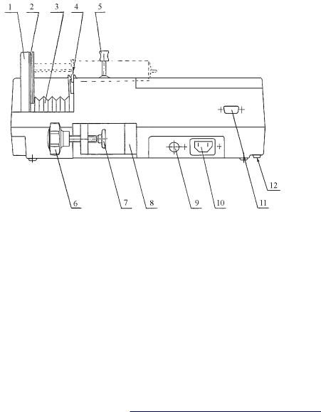
Fig. 2.
Rear view of the pumps SP-12S Pro, SEP-12S Plus and SEP-10S Plus
1 |
Ð |
syringe driver arm |
6 |
Ð |
handle |
2 |
Ð |
slot for inserting the push- |
7 |
Ð |
cap |
|
|
button of the syringe |
8 |
Ð |
mounting pole clamp |
|
|
plunger |
9 |
Ð |
fuse holder |
3 |
Ð |
rubber bellows |
10 |
Ð mains inlet |
|
4 |
Ð |
slot for inserting the finger |
11 |
Ð MFC* |
|
|
|
grips of the syringe barrel |
12 |
Ð Audio volume control* |
|
5 |
Ð |
syringe clamp |
|
|
* Ð optional |
7
Service manual

4 . KEYBOARD DESCRIPTION
...
8
Ðgreen indicator, indicating pump connected to the AC line 220Ð 230V and battery charging.
Ð green LED is on when pump runs on internal battery; flashing if LOW BATTERY alarm condition occurs.
Ð during infusion, three yellow LEDs are sequentially flashing. If the rightmost LED is on permanently Ð the infusion is stopped.
Ð key to switch the pump on/off; keep it pressed for several seconds in order to switch off.
Ð key to start/stop the infusion.
Ð key to move the syringe driver arm rapidly to the left-hand side during syringe insertion or to initiate the Bolus mode; it is also intended for air removal from the extension set after syringe insertion.
Ð key to move the syringe driver arm to the right-hand side.
Ðkeys to scroll up/down the list of parameters and syringe brands or answer positively or negatively the dialog questions.
Ðkey to select dimensions of parameters when programming (only in SP-12S Pro and SEP-12S Plus).
Ðkey to program (modify) parameters. Pressing it once more restores previous values.
Ðkey to confirm the selected parameter.
Ðnumerical keys to enter digits of the parameter being programmed.
Ðkey to select additional functions or to review programmed parameters.
Ðkey to cancel the numerical value or the meaning of the parameter or silence the alarm signal. It deletes TOTAL INFUSED and INFUSED DOSE values and clears the numerical value on display when programming.
SP-12S Pro, SEP-12S Plus and SEP-10S Plus syringe infusion pumps

5 . TECHNICAL DESCRIPTION
5 . 1 . P R I N C I P L E O F O P E R A T I O N
υThe pump is intended for precise dosing of medicine at the rate programmed by the operator. The speed of syringe driver arm is set by the microcontroller, which evaluates the syringe volume and features of the syringe model. The microcontroller controls the step motor, which transfers movement to the syringe driver arm via the helical gear. The microcontroller monitors also voltage of the internal battery, mains voltage, occlusion pressure, Bolus volume and rate. Data on pump status and programming data are outputted to the alphanumeric 2x16 symbol display. Operation of the microcontroller is monitored by the special circuit (watch-dog), which unconditionally switches off the motor in case of failure of the microcontroller.
In case of mains voltage failure, the pump automatically continues its operation being powered from the internal rechargeable battery and warns the operator on this by means of audible and visual signals.
5.2. ELECTRICAL SCHEMATIC DIAGRAM OF THE PUMP
5 . 2 . 1 . P r i n c i p l e o f o p e r a t i o n
υThe electrical schematic diagram of the pumps are presented in theÊAnnex A, B.The interconnection diagram of the pump is presented in Annex C. Diagrams of the pump are composed of the following main parts:
ωpower supply;
ωkeyboard;
ωdrive;
ωsyringe size sensor;
ωelectronic board B7043.
9
Service manual

5 . 2 . 2 . P o w e r s u p p l y
υ220-230 VAC (or 115 VAC) voltages via the mains filter MF1 and fuse F1 is fed to the primary winding of the step-down transformer TR1. Voltage from the secondary winding of the transformer TR1 reduced to 10-11 VAC is rectified by the diode bridge D1 and capacitor C1 (1113,5 VDC) and via the fuse F1(A2) is fed to the remaining part of the circuit. The resistor R1 sets the charging current for the rechargeable batteries GB1, GB2 which shall be in range of (70-130) mA. When the pump is powered from the internal battery, power supply current goes via the diode D2.The fuse F2(A2) protects batteries by limiting charging and load currents.There is fed a signal to the electronic board B7043 via the diode D3 and the resistor R2 informing the pump is powered from the external mains of 50/60 Hz, 220-230 VAC (or 115 VAC). The electronic board B7043 controls the buzzer Z1.
5 . 2 . 3 . K e y b o a r d
υThe keyboard is composed of 21 keys (SEP-10S Plus 20 keys) in form of a matrix having 7 inputs and 3 outputs. Electronic board B7043 performs scanning of the keyboard and reading of information from it. The key ON/OFF controls the circuit of electronic power supply switch located on the electronic board B7043.
5 . 2 . 4 . D r i v e
υThe stepper motor SM1 rotates the lead screw with a nut on it converting rotating movement of the motor to linear movement of the tube. The tube supported by four guiding bearings is connected to the syringe driver arm. Marginal positions of the tube with syringe driver arm
are limited by:
ω limit switch S1 at the right extreme position which is actuated by the end of the tube;
10
SP-12S Pro, SEP-12S Plus and SEP-10S Plus syringe infusion pumps
ω rotational optical sensor TAX1 at the left extreme position when the tube covers the raster of rotating coupling of the optical sensor TAX1.
In case of occlusion when pressure in the syringe increases to the prohibited level, it stops movement of the syringe driver arm and at the same rotation of the stepper motor SM1.
Rotation of the stepper motor is controlled by the optical sensor TAX1 which reads a signal, reflected from the raster of rotational coupling. This signal is fed to the microcontroller U18 located on the electronic board B7043, and this signal switches on the emergency signal.There is some delay between beginning of occlusion on one hand and stepper motor SM1 stopping and emergency signal actuation on the other hand depending on infusion rate, length, thickness and elasticity of extension tube.
υThe pre-alarm switch S2 is activated when the distance between syringe finger flange and syringe thumb rest is
equal to 45 mm. When this distance is equal to 27 mm, the end switch S1 is activated, which in this case acts as the second pre-alarm switch. When the pre-alarm switch has been activated, the pump calculates distance to the end of appropriate syringe. Based on this there are calculated and activated the following warning messages:
Xmin. PREALARM!
where X ≤ 5 min., and
SYRINGE EMPTY!
υIn case of occlusion the stepper motor SM1 executes some number of steps back depending on syringe type. This reduced pressure in the syringe and extension tube and at the same time reduces unwanted Bolus volume injected to the patient when the cause of occlusion is removed.
11
Service manual

5 . 2 . 5 . S y r i n g e s i z e s e n s o r
υSyringe size sensor is implemented as a sliding potentiometer R1. Depending on syringe diameter, potentiometer slider position is changed and its output voltage at the same time, which is linearly proportional to the output resistance of the potentiometer R1.This output voltage is fed to the electronic board B7043.
5 . 3 . ELECTRICAL SCHEMATIC DIAGRAM OF ELECTRONIC BOARD B704 3
υThe electrical schematic diagram of electronic board B7043 is shown in the annex C.
It is composed of the following main parts:
ωmicrocontroller circuit;
ωdisplay circuit;
ωãwatch-dogÓ circuit;
ωstabilized power supply;
ωelectronic power-supply switch circuit;
ωsyringe size sensor signal processing circuit;
ωDAC;
ωpulse current stabilizers;
ωswitches.
5 . 3 . 1 . M i c r o c o n t r o l l e r c i r c u i t
υThere is used the T89C51RD2 microcontroller U18 having internal RAM of 256 bytes for data, internal flash memory of 64 kB and external EEPROM of 32 kB for software and external time keeper SRAM U14 with clock for log.
The quartz resonator Q2 of 12,288 MHz sets clock frequency for microcontroller. The microcontroller U18 selects addresses of the SRAM U14 (lower addresses from port P0 via register U13, higher addresses from port P2 directly).The microcontroller U18 via port P0 and register U11 generates instructions for step motor control,
12
SP-12S Pro, SEP-12S Plus and SEP-10S Plus syringe infusion pumps

writes information to display MD1, writes and reads information to/from SRAM U14, controls the buzzer, LEDs D26, D27, D28 ãRUNÓ. Also via port P0 and register U13, it scans the keyboard. Information from the keyboard is read via register U12 to port P0.
υThe microcontroller U8 AT89C2051 receives information from the microcontroller U18 T89C51RD2 to its inputs P3.0 and P3.2 on step motor rotation direction, period between steps and power.The restart signal for the microcontroller U8 (pin 1) is generated by means of elements C46 and R51 in time of power switching on. When master ãwatch-dogÓ circuit is activated, a high-level signal is applied to the restart input of the microcontroller U8 interrupting its operation.
5 . 3 . 2 . D i s p l a y c i r c u i t
υInformation to display MD1 (addresses and data) is written from the port P0 of microcontroller U18. The resistors R88ÑR91 sets current via transistor T15 and at that same time current for backlighting LED of display MD1. This current shall be equal to 70 ± 10 mA when backlighting is switched on and 10 ± 5 mA when backlighting is switched off.The backlighting current is controlled by the signal from microcontroller U18 via register U10. Resistor R93 defines brightness of the display MD1.
5 . 3 . 3 . Ò W a t c h - d o g Ó c i r c u i t
υThe special ãWatch-dogÓ circuit monitors operation of the microcontroller U18. In case of disturbances in microcontroller U18 operation, this circuit prevents functioning of the pump, stops the motor and activates audible alarm. The basis of master ãWatch-dogÓ circuit is monostable multivibrator U5A, U5B and the trigger U3A. They compose the frequency discriminator with pass-band of 500 Hz to 2 kHz.
13
Service manual

υThe slave watch-dog circuit is composed of elements U17A, D25, C61, C74. When for some reason the pulses cease to arrive to capacitor C61, 0.5 sec later a low-level signal is generated at the output 6 of the Schmitt trigger U17A initiating actuation of the master watch-dog circuit.
5 . 3 . 4 . S t a b i l i z e d p o w e r s u p p l y
υThere are used two stabilized +5VDC voltages Vcc1 and Vcc2.The voltage Vcc1 is supplied to the microcontroller U18, ãWatch-dogÓ circuit and electronic power supply switch. When powering of the pump is switched off by means of the key ON/OFF, voltage Vcc1 goes down to 2V (voltage Vcc2 becomes equal to 0V).
The IC U1 is the voltage stabilizer.The transistor T1 is a current amplifier and the transistor T2 is a power supply switch.
Adjustable resistor R13 sets threshold for emergency signal actuation on discharge of batteries GB1, GB2 (voltage on pin 7 of the IC U1 shall go down from +5V to 0V when battery voltage drops to 9.2V).
υDC/DC converter U2 generates necessary negative voltage of Ñ(4,7Ö5,0)V at its output (pin 5).
5 . 3 . 5 . E l e c t r o n i c p o w e r - s u p p l y s w i t c h
υWhen the pump is switched on by pressing the key ON/OFF, there is set at the same time inhibition to switch it off, i.e. the low-level signal is applied to pin 13 of the trigger U3B. This inhibition may be removed either by the microcontroller U18 having received an appropriate request or by the ãwatch-dogÓ activated. The microcontroller U18 via the input T0 receives information on depressed key ON/OFF. Then when the key ON/OFF is kept depressed for 3 sec the microcontroller U18 switches off the pump by applying high-level pulse to the pin 10 of the trigger U3B.
14
SP-12S Pro, SEP-12S Plus and SEP-10S Plus syringe infusion pumps

Electronic power-supply switch output signals control the power supply stabilizer and switch the microcontroller U18 to mode of low power consumption or to normal mode. These signals via capacitor C67 generate start (reset) pulse for microcontroller U18.
5 . 3 . 6 . S y r i n g e s i z e s e n s o r s i g n a l p r o c e s s i n g c i r c u i t
υThe voltage taken from the potentiometer for syringe diameter and proportional to the syringe diameter is fed to ADC U7. Information on syringe diameter in digital form from U7 is transferred via the serial port to the input P1.0 of the microcontroller U18.
5 . 3 . 7 . D A C ( d i g i t a l t o a n a l o g c o n v e r t e r )
υ The DAC is composed of resistor network, amplifier U6A and inverter U6B. Depending on the code at the port P1 of the microcontroller U8, voltage at the output 7 of the operational amplifier U6A is changing in the range 0 to - 0.4V. The inverter is based on the operational amplifier U6B and converts this voltage to positive one. The voltage from the output 1 of U4B is fed to two (separate for each phase of the motor) sample-and-hold units for analogous signal, implemented on elements T6, C55 and T7, C57 accordingly. There are generated two independent voltages on capacitors C11, C12 being proportional to currents flowing through motor phases.
5 . 3 . 8 . P u l s e c u r r e n t s t a b i l i z e r s
υThe pulse current stabilizer for the 1st phase is composed of elements U15A,T5, R56, D18, D19, L4, R61, R60, and that for the 2nd phase - of elements U15B,T4, R57, D15, D20, L5, R67, R69. Further is described operation of the pulse current stabilizer for the 1st phase only. The voltage from the capacitor C55 is fed to the inverting input 2 of
15
Service manual

the comparator U15A. The non-inverting input of the comparator receives the signal equal to voltage drop across the resistors R61, R60 and proportional to current flowing through them.When this voltage is lower than that on the capacitor C55, then transistor T5 becomes open.Then the power source VCC-NS is connected to the inductor L4 and the current through it starts to increase.When voltage drop across resistors R61, R60 exceeds voltage from the capacitor C55, the transistor T5 becomes closed and current through the reactor L4 starts to decrease.The new cycle is started, and its frequency depends on inductance of the reactor L4, phase current value and comparator hysteresis.
5 . 3 . 9 . S w i t c h e s
υCurrents for both phases flow to the common conductors of motor phase coils via accumulating reactors L4 and L5. Direction of motor rotation is defined by appropriate order of current switching in both phase coils.This switching is implemented by current switches T8,T9 and T10, T13 for the 1st and the 2nd phases accordingly.
16
SP-12S Pro, SEP-12S Plus and SEP-10S Plus syringe infusion pumps

6 . SETUP MENU
υIn order to access optional functions or certain parameters, keep the START/STOP key in pressed position and switch the pump on by pressing the ON/OFF key.When short beep is heard, release the START/STOP key, enter appropriate code with the numerical keys and confirm it by pressing the ENTER key.
The total list of optional functions/parameters and their access codes are presented in the Table 1:
Table 1
CODE |
NAME |
DESCRIPTION |
NOTE |
|
|
|
|
100 |
Pump modes |
|
|
|
|
|
|
137 |
Syringe list |
|
|
|
|
|
|
147 |
Drug list |
|
|
|
|
|
|
157 |
DEFAULT GRUG SET |
restoring default |
|
|
|
(manufacturerÕs) jist of drug |
|
|
|
|
|
237 |
Functions |
Configurable |
|
|
|
functions/parameters |
|
|
|
|
|
257 |
DEFAULT |
restoring default |
|
|
PARAMETERS SET |
(manufacturerÕs) parameters |
|
|
|
|
|
337 |
LANGUAGE SET: |
|
|
|
ENGLISH and other |
installation of dialog language |
|
|
|
|
|
537 |
SYRINGE SIZE |
to calibrate syringe sensor |
for calibration needs spacers: |
|
CALIBRATION |
|
B8640027, B8640027-01, |
|
|
|
B8640027-02, B8640027-03 |
|
|
|
|
547 |
OCCLUSION |
calibration of occlusion level |
|
|
CALIBRATION |
|
|
|
|
|
|
637 |
DATE, TIME |
setting of date and time |
|
|
|
|
|
υList of optional functions may be reviewed using the scroll keys. If displayed name is marked with the asterisk, it means that function is active. To activate an inactive function press the ENTER key, and the asterisk will appear in front of the item name.
To deactivate a function, press the C key. The asterisk shall disappear.
17
Service manual

υ To change flow rate upper limit select appropriate item, press the PROG key, enter the new value using the numeric keys and confirm it by pressing the ENTER key.
υTo enter a new drug name open the drug list and select the drug name to be replaced by the new one. Press the PROG key, and enter the new drug name using keys in accordance with the table below (e.g. to enter letter Z press the 9 key four times):
Key |
1 |
2 |
3 |
4 |
5 |
6 |
7 |
8 |
9 |
0 |
. |
YES |
NO, C |
|
|
|
|
|
|
|
|
|
|
|
|
|
|
Cha- |
1 |
A,B, |
D,E, |
G,H, |
J, K, |
M, N, |
P,Q, |
T, U, |
W, X, |
%, 0, |
. |
Space |
Backspace |
rac- |
|
C,2 |
F, 3 |
I, 4 |
L, 5 |
O, 6 |
R, S, 7 |
V, 8 |
Y, Z, 9 |
/, - |
|
|
|
ter |
|
|
|
|
Confirm the new drug name by pressing the ENTER key.
NOTES:
1.Entered character can be reset by means of the C or NO keys.
2.Old drug name can be restored by means of the PROG key until new name is confirmed.
υTo exit setup menu press the START/STOP key.
υTo change date and time settings enter new values when appropriate demand is displayed and press the ENTER key to confirm them and exit setup menu.
ATTENTION !
It is recommended to minimize number of parameters, types of syringes, drug names and other functions leaving only that necessary for work. It will help to avoid errors in parameters programming and thereby decrease patientÕs risk.
υIf the high occlusion level value after actions specified in section 7.5 are performed is beyond specified limits, occlusion level shall be calibrated. For this sake factual value of high occlusion level pressure obtained during testing is entered into pump.
Typical value for CORRECT END is 60 kPa.
18
SP-12S Pro, SEP-12S Plus and SEP-10S Plus syringe infusion pumps
 Loading...