

Page 1

SP-12S Pro, SEP-12S Plus,
SEP-10S Plus
SYRINGE INFUSION PUMPS
SERVICE MANUAL
BS037016EN-P02
Page 2

CONTENTS
1. INTRODUCTION . . . . . . . . . . . . . . . . . . . . . . . . . . . . . . . . . . . . . . . . . . . . . . 4
2. TECHNICAL DATA . . . . . . . . . . . . . . . . . . . . . . . . . . . . . . . . . . . . . . . . . . . . . 5
3. EXTERNAL VIEW . . . . . . . . . . . . . . . . . . . . . . . . . . . . . . . . . . . . . . . . . . . . . 6
4. KEYBOARD DESCRIPTION . . . . . . . . . . . . . . . . . . . . . . . . . . . . . . . . . . . . . 8
5. TECHNICAL DESCRIPTION
5.1. PRINCIPLE OF OPERATION . . . . . . . . . . . . . . . . . . . . . . . . . . . . . . . . . 9
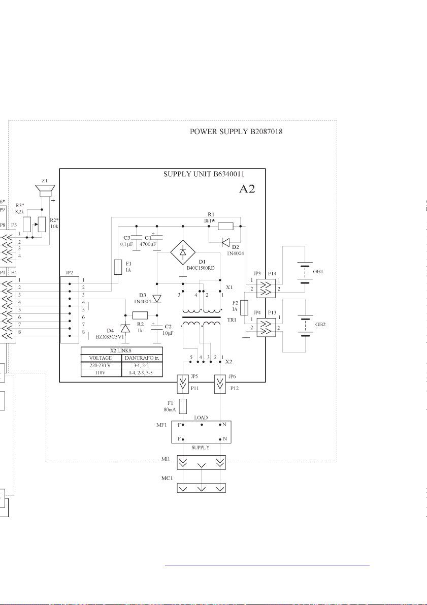
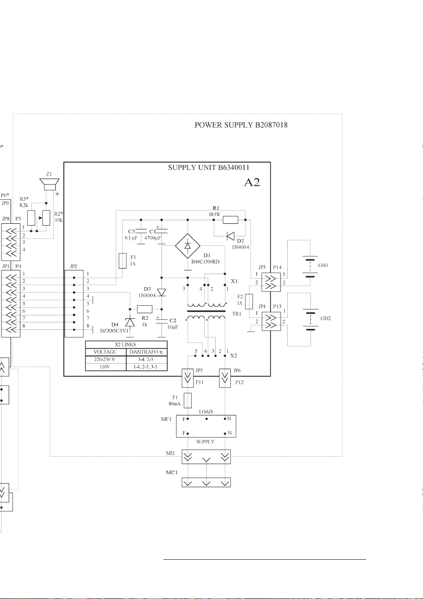
5.2. ELECTRICAL SCHEMATIC DIAGRAM OF THE PUMP . . . . . . . . . . . . . . 9
5.3. ELECTRICAL SCHEMATIC DIAGRAM
OF ELECTRONIC BOARD B7043 . . . . . . . . . . . . . . . . . . . . . . . . . . . . 12
6. SETUP MENU . . . . . . . . . . . . . . . . . . . . . . . . . . . . . . . . . . . . . . . . . . . . . . . 17
7. CHECKING PARAMETERS
7.1. MEANS REQUIRED FOR PARAMETERS CHECKING . . . . . . . . . . . . . 19
7.2. CHECKING INFUSION VOLUME . . . . . . . . . . . . . . . . . . . . . . . . . . . . . 19
7.3. CHECKING INFUSION RATE . . . . . . . . . . . . . . . . . . . . . . . . . . . . . . . . 20
7.4. CHECKING BOLUS VOLUME . . . . . . . . . . . . . . . . . . . . . . . . . . . . . . . 20
7.5. CHECKING OCCLUSION PRESSURE . . . . . . . . . . . . . . . . . . . . . . . . . 21
8. CHECKING ALARM SIGNALS . . . . . . . . . . . . . . . . . . . . . . . . . . . . . . . . . . 22
9. TROUBLESHOOTING . . . . . . . . . . . . . . . . . . . . . . . . . . . . . . . . . . . . . . . . . 28
10. PUMP REPAIR
10.1. DISASSEMBLING THE PUMP . . . . . . . . . . . . . . . . . . . . . . . . . . . . . . 32
10.2. REPLACING INTERNAL BATTERY . . . . . . . . . . . . . . . . . . . . . . . . . . . 32
10.3. REPLACING RUBBER BELLOWS . . . . . . . . . . . . . . . . . . . . . . . . . . . 32
10.4. REPLACING OPTICAL SENSOR TAX1 . . . . . . . . . . . . . . . . . . . . . . . . 33
10.5. REPLACING END SWITCH S1 . . . . . . . . . . . . . . . . . . . . . . . . . . . . . . 33
10.6. REPLACING PRE-ALARM SWITCH S2 . . . . . . . . . . . . . . . . . . . . . . . . 33
10.7. REPLACING SYRINGE SENSOR S3 . . . . . . . . . . . . . . . . . . . . . . . . . . 34
10.8. REPLACING ELECTRONIC BOARD . . . . . . . . . . . . . . . . . . . . . . . . . . 34
10.9. REPLACING KEYBOARD . . . . . . . . . . . . . . . . . . . . . . . . . . . . . . . . . . 34
10.10. REPLACING MICROCONTROLLER . . . . . . . . . . . . . . . . . . . . . . . . . 35
2
SP-12S Pro, SEP-12S Plus and SEP-10S Plus syringe infusion pumps
Page 3

10.11. REPLACING SYRINGE SIZE SENSOR . . . . . . . . . . . . . . . . . . . . . . . 35
10.12. REPLACING BUZZER UNIT . . . . . . . . . . . . . . . . . . . . . . . . . . . . . . . 35
10.13. REPLACING POWER SUPPLY INLET . . . . . . . . . . . . . . . . . . . . . . . . 36
10.14. REPLACING SUPPLY UNIT . . . . . . . . . . . . . . . . . . . . . . . . . . . . . . . 36
ANNEX A
ELECTRICAL SCHEMATIC DIAGRAM
OF THE PUMPS SP-12S Pro and SEP-12S Plus . . . . . . . . . . . . . . . . . . . . . . . . . . 40
ANNEX B
ELECTRICAL SCHEMATIC DIAGRAM OF THE PUMP SEP-10S Plus . . . . . . . . . 42
ANNEX C
INTERCONNECTION DIAGRAM OF THE PUMPS . . . . . . . . . . . . . . . . . . . . . . . . 44
ANNEX D
ELECTRICAL SCHEMATIC DIAGRAM OF ELECTRONIC BOARD B7043 . . . 46
ANNEX E
ASSEMBLY DRAWING OF ELECTRONIC BOARD B7043 . . . . . . . . . . . . . . . . . . 52
ANNEX F
DRAWING OF CABLES FOR MULTIFUNCTIONAL CONNECTOR (MFC) . . . . . . 54
ANNEX G
DESCRIPTION OF ERRORS . . . . . . . . . . . . . . . . . . . . . . . . . . . . . . . . . . . . . . . . . 55
ANNEX H
PREVENTIVE MAINTENANCE CHECKLIST . . . . . . . . . . . . . . . . . . . . . . . . . . . . . 56
ANNEX I
COMPONENT LIST . . . . . . . . . . . . . . . . . . . . . . . . . . . . . . . . . . . . . . . . . . . . . . . . 57
ANNEX J
ACCESSORIES . . . . . . . . . . . . . . . . . . . . . . . . . . . . . . . . . . . . . . . . . . . . . . . . . . . 58
ANNEX K
COMMUNICATION PROTOCOL. TECHNICAL DESCRIPTION . . . . . . . . . . . . . . 59
Service manual
3
Page 4

1. INTRODUCTION
u This SERVICE MANUAL describes how to check,
troubleshoot and repair SP-12S Pro, SEP-12S Plus and
SEP-10S Plus syringe infusion pumps. The purpose and
maintenance of the pumps are described in the appropriate OPERATING INSTRUCTIONS.
If when repairing your pump you have encountered problems, which you cannot solve, or the pump parameters are
changed after the repair, please, in all these cases contact
the manufacturer.
NOTE:
The manufacturer’s authorized personnel may carry
out the technical servicing of the pump only!
4
SP-12S Pro, SEP-12S Plus and SEP-10S Plus syringe infusion pumps
Page 5

2. TECHNICAL DATA
Power supply:
220–230 VAC ±10%, 50/60 Hz, or 115 VAC ±10%, 50/60 Hz,
or internal rechargeable battery
Fuses:
T80 mA/L250 V – for 220–230 VAC
T160 mA/L250 V – for 115 VAC
Power consumption:
10 VA (max)
Internal battery:
9.6 V 1300 mAh NiMH battery
Cordless work time:
8 h (minimum) at 5 ml/h infusion rate;
2 h (minimum) at 100 ml/h infusion rate.
Battery recharging time: 24 hours.
Classification: Class II, CF, splash proof.
RS232 (optional)
12 VDC supply connection (optional)
Nurse Call connection (optional)
Operating temperature range:
+5 to +40 °C.
Storage temperature range:
-20 to +40 °C.
Air pressure:
60 to 106 kPa.
Relative humidity:
90% max., no condensation (operation and storage).
Dimensions:
135 x 305 x 195 mm
Weight:
2.6 kg.
Service manual
5
Page 6
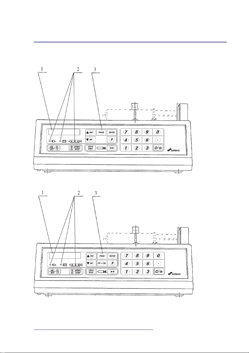
3. EXTERNAL VIEW
Fig. 1.
Front view of the pump SEP-10S Plus
Front view of the pumps SP-12S Pro, SEP-12S Plus
1 – display 2 – indicators 3 – keypad
6
SP-12S Pro, SEP-12S Plus and SEP-10S Plus syringe infusion pumps
Page 7
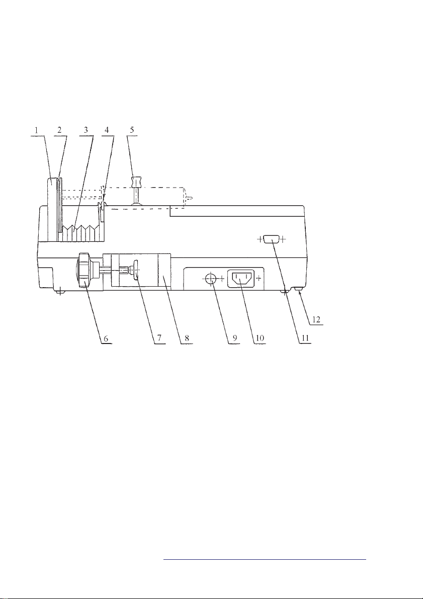
Fig. 2.
Rear view of the pumps SP-12S Pro, SEP-12S Plus and SEP-10S Plus
1 – syringe driver arm
2 – slot for inserting the push-
button of the syringe
plunger
3 – rubber bellows
4 – slot for inserting the finger
grips of the syringe barrel
5 – syringe clamp
6 – handle
7 – cap
8 – mounting pole clamp
9 – fuse holder
10 – mains inlet
11 – MFC*
12 – Audio volume control*
* – optional
7
Service manual
Page 8
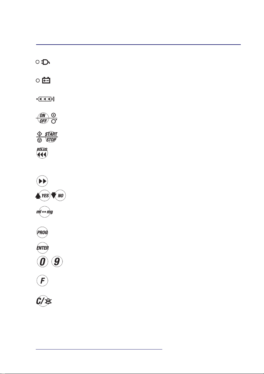
4. KEYBOARD DESCRIPTION
– green indicator, indicating pump connected to the AC line 220–
230V and battery charging.
– green LED is on when pump runs on internal battery; flashing
if LOW BATTERY alarm condition occurs.
– during infusion, three yellow LEDs are sequentially flashing. If
the rightmost LED is on permanently – the infusion is stopped.
– key to switch the pump on/off; keep it pressed for several sec-
onds in order to switch off.
– key to start/stop the infusion.
– key to move the syringe driver arm rapidly to the left-hand side
during syringe insertion or to initiate the Bolus mode; it is also
intended for air removal from the extension set after syringe in-
sertion.
– key to move the syringe driver arm to the right-hand side.
– keys to scroll up/down the list of parameters and syringe brands
or answer positively or negatively the dialog questions.
– key to select dimensions of parameters when programming (only
in SP-12S Pro and SEP-12S Plus).
– key to program (modify) parameters. Pressing it once more re-
stores previous values.
– key to confirm the selected parameter.
...
– numerical keys to enter digits of the parameter being pro-
grammed.
– key to select additional functions or to review programmed pa-
rameters.
– key to cancel the numerical value or the meaning of the param-
eter or silence the alarm signal. It deletes TOTAL INFUSED
and INFUSED DOSE values and clears the numerical value on
display when programming.
8
SP-12S Pro, SEP-12S Plus and SEP-10S Plus syringe infusion pumps
Page 9

5. TECHNICAL DESCRIPTION
5.1. PRINCIPLE OF OPERATION
u The pump is intended for precise dosing of medicine at the
rate programmed by the operator. The speed of syringe
driver arm is set by the microcontroller, which evaluates the
syringe volume and features of the syringe model. The
microcontroller controls the step motor, which transfers
movement to the syringe driver arm via the helical gear.
The microcontroller monitors also voltage of the internal
battery, mains voltage, occlusion pressure, Bolus volume
and rate. Data on pump status and programming data are
outputted to the alphanumeric 2x16 symbol display. Operation of the microcontroller is monitored by the special
circuit (watch-dog), which unconditionally switches off the
motor in case of failure of the microcontroller.
In case of mains voltage failure, the pump automatically
continues its operation being powered from the internal
rechargeable battery and warns the operator on this by
means of audible and visual signals.
5.2. ELECTRICAL SCHEMATIC DIAGRAM OF THE PUMP
5.2.1. Principle of operation
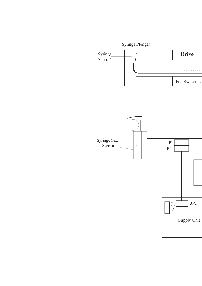
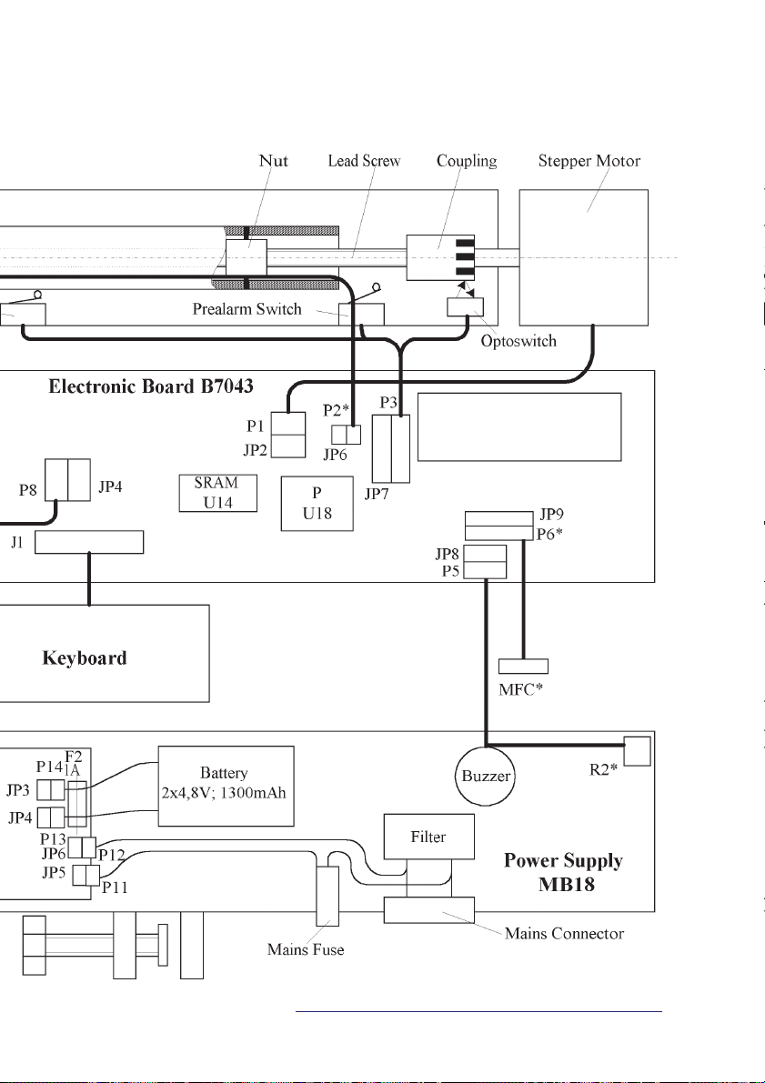
u The electrical schematic diagram of the pumps are pre-
sented in theAnnex A, B. The interconnection diagram of
the pump is presented in Annex C. Diagrams of the pump
are composed of the following main parts:
w power supply;
w keyboard;
w drive;
w syringe size sensor;
w electronic board B7043.
Service manual
9
Page 10

5.2.2. Power supply
u 220-230 VAC (or 115 VAC) voltages via the mains filter
MF1 and fuse F1 is fed to the primary winding of the
step-down transformer TR1. Voltage from the secondary
winding of the transformer TR1 reduced to 10-11 VAC is
rectified by the diode bridge D1 and capacitor C1 (1113,5 VDC) and via the fuse F1(A2) is fed to the remaining part of the circuit. The resistor R1 sets the charging
current for the rechargeable batteries GB1, GB2 which
shall be in range of (70-130) mA. When the pump is
powered from the internal battery, power supply current
goes via the diode D2. The fuse F2(A2) protects batteries
by limiting charging and load currents. There is fed a signal to the electronic board B7043 via the diode D3 and
the resistor R2 informing the pump is powered from the
external mains of 50/60 Hz, 220-230 VAC (or 115 VAC).
The electronic board B7043 controls the buzzer Z1.
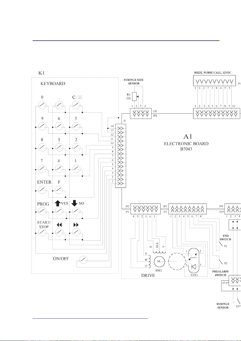
5.2.3. Keyboard
u The keyboard is composed of 21 keys (SEP-10S Plus
20 keys) in form of a matrix having 7 inputs and 3 outputs. Electronic board B7043 performs scanning of the
keyboard and reading of information from it. The key
ON/OFF controls the circuit of electronic power supply
switch located on the electronic board B7043.
5.2.4. Drive
u The stepper motor SM1 rotates the lead screw with a nut
on it converting rotating movement of the motor to linear movement of the tube. The tube supported by four
guiding bearings is connected to the syringe driver arm.
Marginal positions of the tube with syringe driver arm
are limited by:
w limit switch S1 at the right extreme position which is
actuated by the end of the tube;
10
SP-12S Pro, SEP-12S Plus and SEP-10S Plus syringe infusion pumps
Page 11

w rotational optical sensor TAX1 at the left extreme position when the tube covers the raster of rotating coupling of the optical sensor TAX1.
In case of occlusion when pressure in the syringe increases to the prohibited level, it stops movement of the
syringe driver arm and at the same rotation of the stepper motor SM1.
Rotation of the stepper motor is controlled by the optical
sensor TAX1 which reads a signal, reflected from the raster
of rotational coupling. This signal is fed to the microcontroller U18 located on the electronic board B7043, and
this signal switches on the emergency signal. There is some
delay between beginning of occlusion on one hand and
stepper motor SM1 stopping and emergency signal actuation on the other hand depending on infusion rate, length,
thickness and elasticity of extension tube.
u The pre-alarm switch S2 is activated when the distance
between syringe finger flange and syringe thumb rest is
equal to 45 mm. When this distance is equal to 27 mm,
the end switch S1 is activated, which in this case acts as
the second pre-alarm switch. When the pre-alarm switch
has been activated, the pump calculates distance to the
end of appropriate syringe. Based on this there are calculated and activated the following warning messages:
Xmin. PREALARM!Xmin. PREALARM!
Xmin. PREALARM!
Xmin. PREALARM!Xmin. PREALARM!
where X ≤ 5 min., and
SYRINGE EMPTY!SYRINGE EMPTY!
SYRINGE EMPTY!
SYRINGE EMPTY!SYRINGE EMPTY!
u In case of occlusion the stepper motor SM1 executes
some number of steps back depending on syringe type.
This reduced pressure in the syringe and extension tube
and at the same time reduces unwanted Bolus volume
injected to the patient when the cause of occlusion is removed.
Service manual
11
Page 12

5.2.5. Syringe size sensor
u Syringe size sensor is implemented as a sliding poten-
tiometer R1. Depending on syringe diameter, potentiometer slider position is changed and its output voltage at
the same time, which is linearly proportional to the output resistance of the potentiometer R1. This output voltage is fed to the electronic board B7043.
5.3. ELECTRICAL SCHEMATIC DIAGRAM
OF ELECTRONIC BOARD B7043
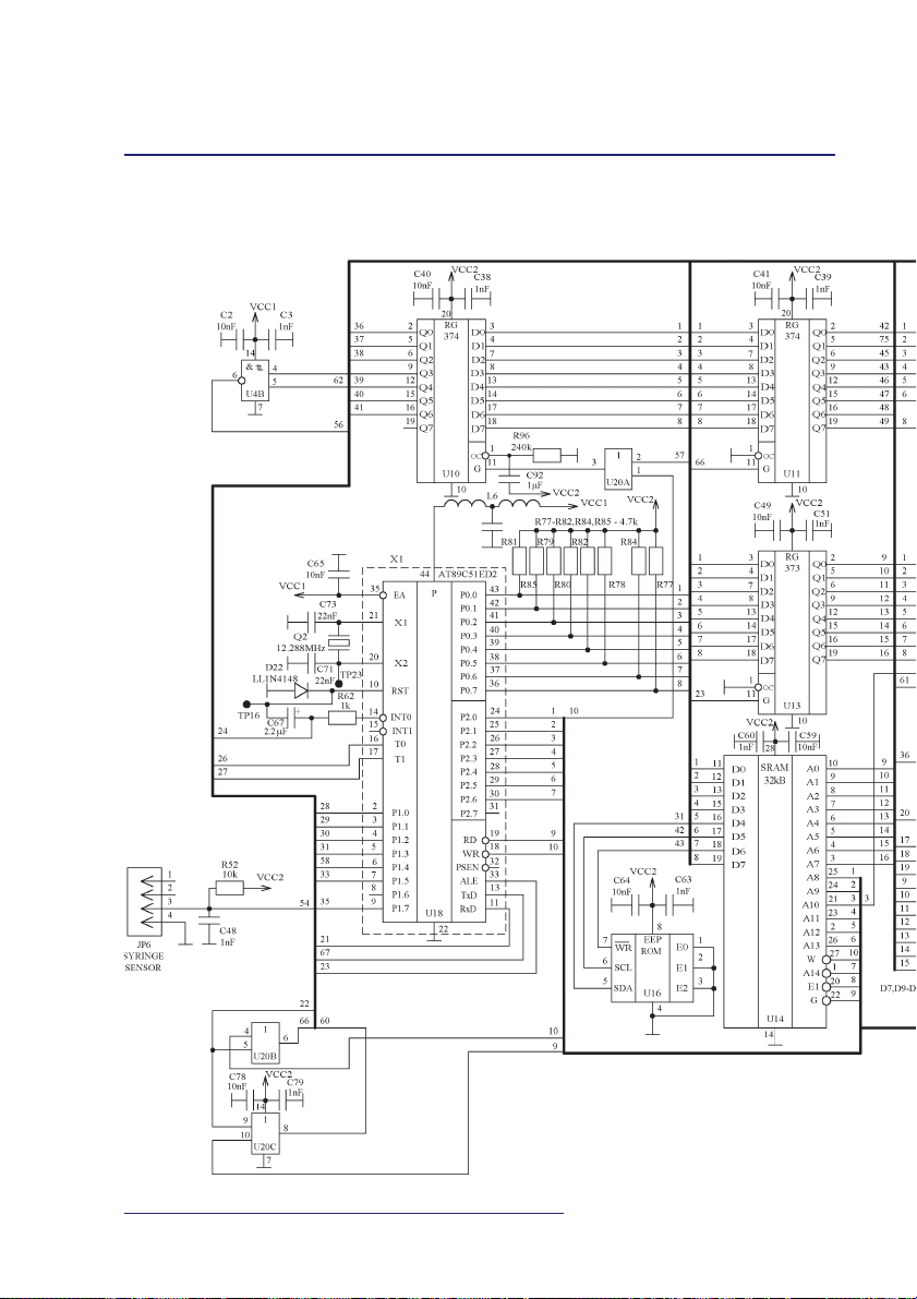
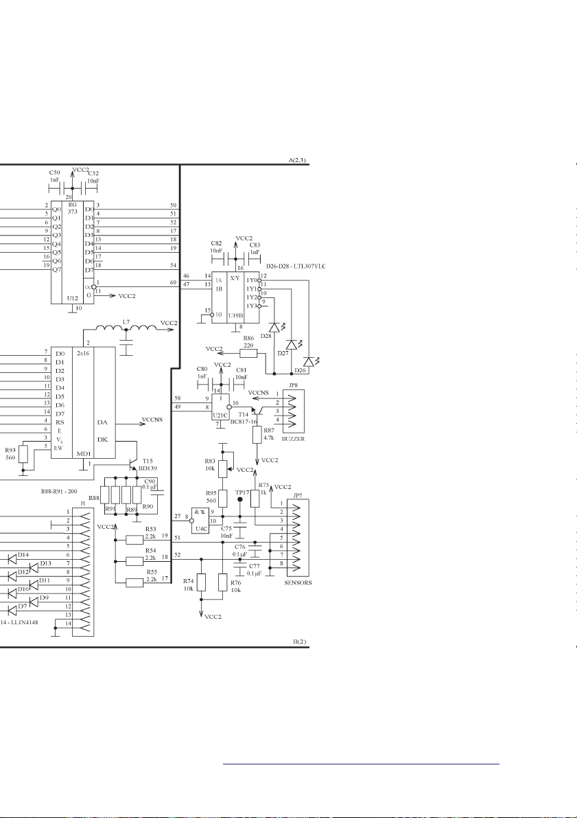
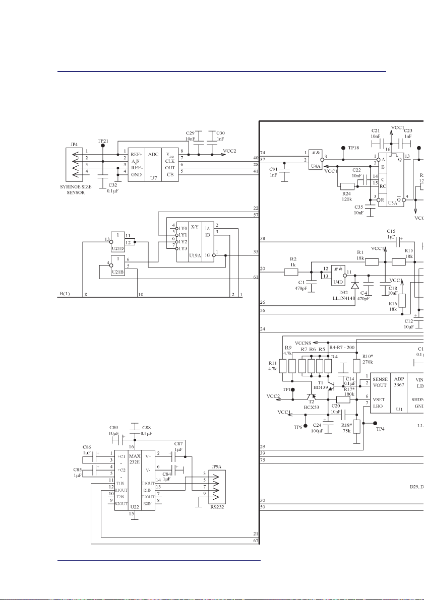
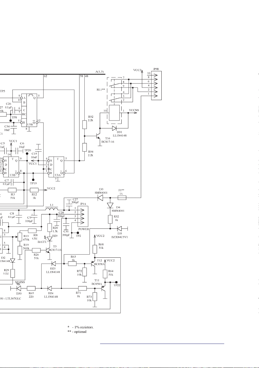
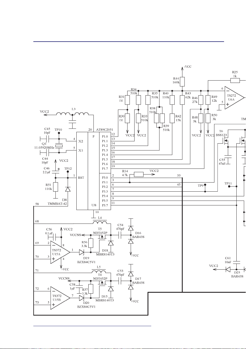
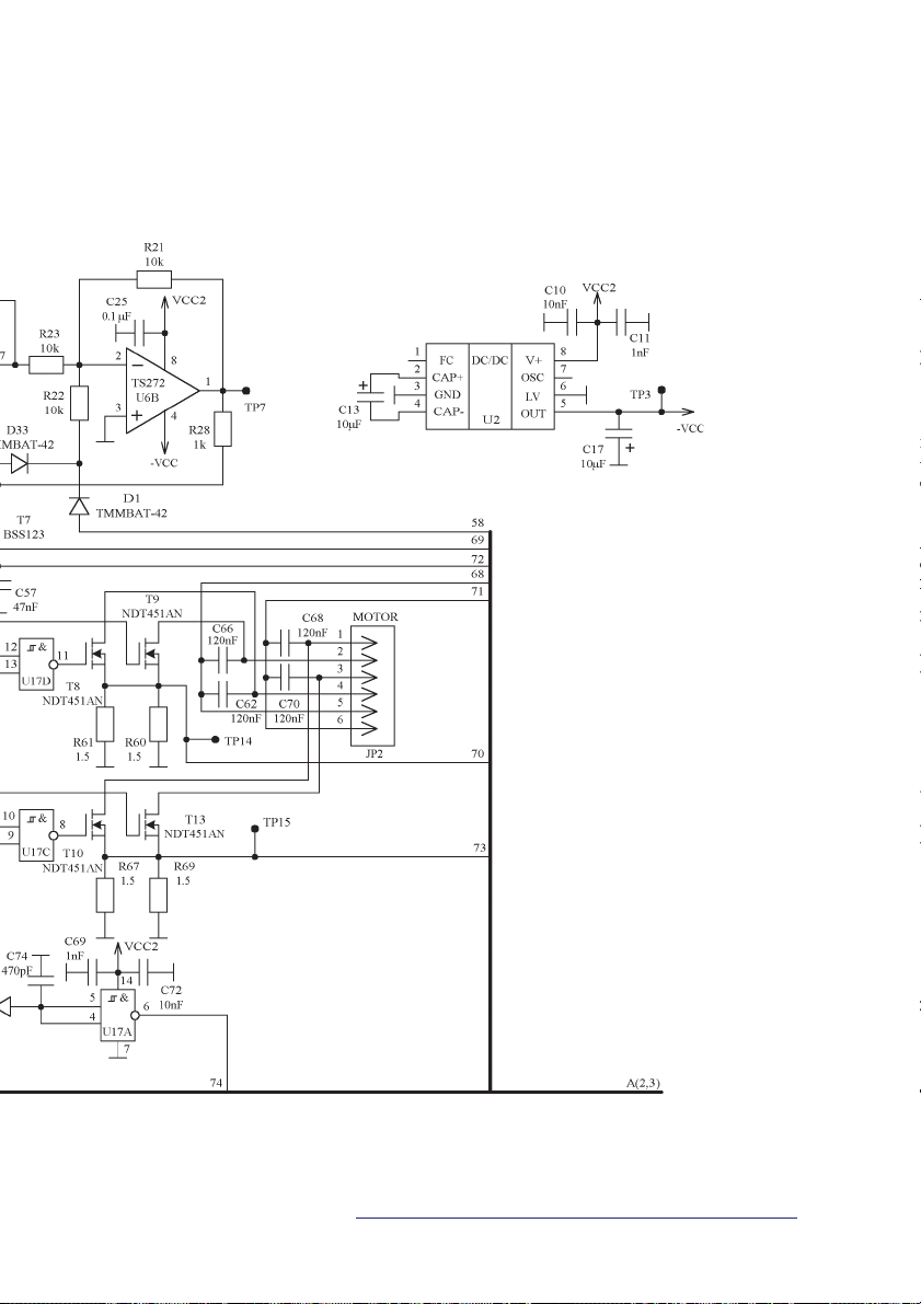
u The electrical schematic diagram of electronic board
B7043 is shown in the annex C.
It is composed of the following main parts:
w microcontroller circuit;
w display circuit;
w „watch-dog” circuit;
w stabilized power supply;
w electronic power-supply switch circuit;
w syringe size sensor signal processing circuit;
w DAC;
w pulse current stabilizers;
w switches.
5.3.1. Microcontroller circuit
u There is used the T89C51RD2 microcontroller U18 having
internal RAM of 256 bytes for data, internal flash memory
of 64 kB and external EEPROM of 32 kB for software and
external time keeper SRAM U14 with clock for log.
The quartz resonator Q2 of 12,288 MHz sets clock frequency for microcontroller. The microcontroller U18 selects addresses of the SRAM U14 (lower addresses from
port P0 via register U13, higher addresses from port P2
directly). The microcontroller U18 via port P0 and register U11 generates instructions for step motor control,
12
SP-12S Pro, SEP-12S Plus and SEP-10S Plus syringe infusion pumps
Page 13

writes information to display MD1, writes and reads information to/from SRAM U14, controls the buzzer, LEDs
D26, D27, D28 „RUN”. Also via port P0 and register
U13, it scans the keyboard. Information from the keyboard is read via register U12 to port P0.
u The microcontroller U8 AT89C2051 receives informa-
tion from the microcontroller U18 T89C51RD2 to its
inputs P3.0 and P3.2 on step motor rotation direction,
period between steps and power. The restart signal for the
microcontroller U8 (pin 1) is generated by means of elements C46 and R51 in time of power switching on.
When master „watch-dog” circuit is activated, a high-level
signal is applied to the restart input of the microcontroller U8 interrupting its operation.
5.3.2. Display circuit
u Information to display MD1 (addresses and data) is writ-
ten from the port P0 of microcontroller U18. The resistors R88—R91 sets current via transistor T15 and at that
same time current for backlighting LED of display MD1.
This current shall be equal to 70 ± 10 mA when backlighting is switched on and 10 ± 5 mA when backlighting
is switched off. The backlighting current is controlled by
the signal from microcontroller U18 via register U10. Resistor R93 defines brightness of the display MD1.
5.3.3. “Watch-dog” circuit
u The special „Watch-dog” circuit monitors operation of
the microcontroller U18. In case of disturbances in
microcontroller U18 operation, this circuit prevents functioning of the pump, stops the motor and activates audible alarm. The basis of master „Watch-dog” circuit is
monostable multivibrator U5A, U5B and the trigger
U3A. They compose the frequency discriminator with
pass-band of 500 Hz to 2 kHz.
Service manual
13
Page 14

u The slave watch-dog circuit is composed of elements
U17A, D25, C61, C74. When for some reason the pulses
cease to arrive to capacitor C61, 0.5 sec later a low-level
signal is generated at the output 6 of the Schmitt trigger
U17A initiating actuation of the master watch-dog circuit.
5.3.4. Stabilized power supply
u There are used two stabilized +5VDC voltages Vcc1 and
Vcc2. The voltage Vcc1 is supplied to the microcontroller
U18, „Watch-dog” circuit and electronic power supply
switch. When powering of the pump is switched off by
means of the key ON/OFF, voltage Vcc1 goes down to 2V
(voltage Vcc2 becomes equal to 0V).
The IC U1 is the voltage stabilizer. The transistor T1 is a
current amplifier and the transistor T2 is a power supply
switch.
Adjustable resistor R13 sets threshold for emergency signal actuation on discharge of batteries GB1, GB2 (voltage on pin 7 of the IC U1 shall go down from +5V to
0V when battery voltage drops to 9.2V).
u DC/DC converter U2 generates necessary negative volt-
age of —(4,7÷5,0)V at its output (pin 5).
5.3.5. Electronic power-supply switch
u When the pump is switched on by pressing the key
ON/OFF, there is set at the same time inhibition to
switch it off, i.e. the low-level signal is applied to pin
13 of the trigger U3B. This inhibition may be removed
either by the microcontroller U18 having received an appropriate request or by the „watch-dog” activated. The
microcontroller U18 via the input T0 receives information on depressed key ON/OFF. Then when the key
ON/OFF is kept depressed for 3 sec the microcontroller
U18 switches off the pump by applying high-level pulse
to the pin 10 of the trigger U3B.
14
SP-12S Pro, SEP-12S Plus and SEP-10S Plus syringe infusion pumps
Page 15

Electronic power-supply switch output signals control the
power supply stabilizer and switch the microcontroller
U18 to mode of low power consumption or to normal
mode. These signals via capacitor C67 generate start (reset) pulse for microcontroller U18.
5.3.6. Syringe size sensor signal
processing circuit
u The voltage taken from the potentiometer for syringe di-
ameter and proportional to the syringe diameter is fed to
ADC U7. Information on syringe diameter in digital
form from U7 is transferred via the serial port to the input P1.0 of the microcontroller U18.
5.3.7. DAC (digital to analog converter)
u The DAC is composed of resistor network, amplifier U6A
and inverter U6B. Depending on the code at the port P1
of the microcontroller U8, voltage at the output 7 of the
operational amplifier U6A is changing in the range 0 to -
0.4V. The inverter is based on the operational amplifier
U6B and converts this voltage to positive one. The voltage from the output 1 of U4B is fed to two (separate for
each phase of the motor) sample-and-hold units for
analogous signal, implemented on elements T6, C55 and
T7, C57 accordingly. There are generated two independent voltages on capacitors C11, C12 being proportional
to currents flowing through motor phases.
5.3.8. Pulse current stabilizers
u The pulse current stabilizer for the 1st phase is composed
of elements U15A, T5, R56, D18, D19, L4, R61, R60, and
that for the 2nd phase - of elements U15B, T4, R57, D15,
D20, L5, R67, R69. Further is described operation of the
pulse current stabilizer for the 1st phase only. The voltage
from the capacitor C55 is fed to the inverting input 2 of
Service manual
15
Page 16

the comparator U15A. The non-inverting input of the
comparator receives the signal equal to voltage drop across
the resistors R61, R60 and proportional to current flowing through them. When this voltage is lower than that on
the capacitor C55, then transistor T5 becomes open. Then
the power source VCC-NS is connected to the inductor
L4 and the current through it starts to increase. When voltage drop across resistors R61, R60 exceeds voltage from the
capacitor C55, the transistor T5 becomes closed and current through the reactor L4 starts to decrease. The new cycle is started, and its frequency depends on inductance of
the reactor L4, phase current value and comparator hysteresis.
5.3.9. Switches
u Currents for both phases flow to the common conductors
of motor phase coils via accumulating reactors L4 and L5.
Direction of motor rotation is defined by appropriate order of current switching in both phase coils. This switching is implemented by current switches T8, T9 and T10,
T13 for the 1st and the 2nd phases accordingly.
16
SP-12S Pro, SEP-12S Plus and SEP-10S Plus syringe infusion pumps
Page 17

6. SETUP MENU
u In order to access optional functions or certain param-
eters, keep the START/STOP key in pressed position and
switch the pump on by pressing the ON/OFF key. When
short beep is heard, release the START/STOP key, enter
appropriate code with the numerical keys and confirm it
by pressing the ENTER key.
The total list of optional functions/parameters and their
access codes are presented in the Table 1:
Table 1
CODE NAME DESCRIPTION NOTE
100 Pump modes
137 Syringe list
147 Drug list
157 DEFAULT GRUG SET restoring default
237 Functions Configurable
257 DEFAULT restoring default
PARAMETERS SET (manufacturer’s) parameters
337 LANGUAGE SET:
ENGLISH and other installation of dialog language
537 SYRINGE SIZE to calibrate syringe sensor for calibration needs spacers:
CALIBRATION B8640027, B8640027-01,
547 OCCLUSION calibration of occlusion level
CALIBRATION
637 DATE, TIME setting of date and time
(manufacturer’s) jist of drug
functions/parameters
B8640027-02, B8640027-03,
u List of optional functions may be reviewed using the
scroll keys. If displayed name is marked with the asterisk,
it means that function is active. To activate an inactive
function press the ENTER key, and the asterisk will appear in front of the item name.
To deactivate a function, press the C key. The asterisk
shall disappear.
Service manual
17
Page 18

u To change flow rate upper limit select appropriate item, press the
PROG key, enter the new value using the numeric keys and confirm
it by pressing the ENTER key.
u To enter a new drug name open the drug list and select the drug name
to be replaced by the new one. Press the PROG key, and enter the new
drug name using keys in accordance with the table below (e.g. to enter letter Z press the 9 key four times):
Key 1 2 3 4 5 6 7 8 9 0 . YES NO, C
Cha-
1 A,B, D,E, G,H, J, K, M, N, P,Q, T, U, W, X, %, 0, . Space Backspace
racter
C,2 F, 3 I, 4 L, 5 O, 6 R, S, 7 V, 8 Y, Z, 9 /, -
Confirm the new drug name by pressing the ENTER key.
NOTES:
1. Entered character can be reset by means of the C or NO
keys.
2. Old drug name can be restored by means of the PROG key
until new name is confirmed.
u To exit setup menu press the START/STOP key.
u To change date and time settings enter new values when appropriate
demand is displayed and press the ENTER key to confirm them and
exit setup menu.
ATTENTION !
It is recommended to minimize number of parameters, types
of syringes, drug names and other functions leaving only that
necessary for work. It will help to avoid errors in parameters
programming and thereby decrease patient’s risk.
u If the high occlusion level value after actions specified in section 7.5 are
performed is beyond specified limits, occlusion level shall be calibrated.
For this sake factual value of high occlusion level pressure obtained during testing is entered into pump.
Typical value for CORRECT END is 60 kPa.
18
SP-12S Pro, SEP-12S Plus and SEP-10S Plus syringe infusion pumps
Page 19

7. CHECKING PARAMETERS
7.1. MEANS REQUIRED FOR PARAMETERS CHECKING
u Prepare the following means:
w 50 ml BD Plastipak syringe,
w standard 90 cm long extension tube,
w stop-watch,
w glass test-tube with graduation (one point equal
to 0.1 ml), 60 ml or more volume,
w pressure gauge with graduation up to 160 kPa,
(accuracy 2.5%).
NOTE:
Programming infusion parameters, filling the syringe and extension tube with drug solution, inserting the syringe into the pump and starting infusion
are described in the OPERATING INSTRUCTIONS of the pump.
7.2. CHECKING INFUSION VOLUME
u Take the 50 ml BD Plastipak syringe with extension tube
connected to it and fill it with distilled water up to the
point of 55 ml. Insert the syringe into the pump and confirm the 50 ml BD Plastipak syringe.
Program the following infusion parameters:
w infusion rate — 100 ml/h,
w volume limit — 50 ml,
w occlusion pressure level — HIGH.
Expel the air from the extension tube. Insert the free end
of the extension tube into the graduated test-tube and
start the infusion. When the infusion is finished, the
measured volume in the test-tube shall differ from the
programmed volume not more than by ± 1 ml (± 2%).
Service manual
19
Page 20

7.3. CHECKING INFUSION RATE
u Take the 50 ml BD Plastipak syringe with extension tube
connected to it and fill it with distilled water up to the
point of 55 ml. Insert the syringe into the pump and confirm the 50 ml BD Plastipak syringe.
Program the following infusion parameters:
w infusion time — 12 min,
w volume limit — 10 ml,
w occlusion pressure level — HIGH.
Expel the air from the extension tube. Insert the free end
of the extension tube into the graduated test-tube and
start the infusion. Measure infusion time by the stopwatch and record the volume in the test-tube at the end
of infusion. Calculate the infusion rate. It shall be
50 ml/h ± 1 ml/h (± 2%).
7.4. CHECKING BOLUS VOLUME
u Take the 50 ml BD Plastipak syringe with an extension
tube connected to it and fill it with distilled water up to
the point 50 ml. Insert the syringe into the pump and
confirm the 50 ml BD Plastipak syringe.
Program the following infusion parameters:
w infusion rate — 50 ml/h,
w volume limit — 50 ml,
w bolus rate — 100 ml/h,
w bolus dose — 20 ml,
w occlusion pressure level — HIGH.
Expel the air from the extension tube. Insert the free end
of the extension tube into the graduated test-tube and
start the infusion. Record the volume delivered into the
test-tube and starts the Bolus mode. Record the volume
in the test-tube at the end of the Bolus cycle.
The difference of these two volumes shall be 20 ml ± 0.4 ml
(± 2%).
20
SP-12S Pro, SEP-12S Plus and SEP-10S Plus syringe infusion pumps
Page 21

7.5. CHECKING OCCLUSION PRESSURE
u Take the 50 ml BD Plastipak syringe with an extension
tube connected to it and fill it with distilled water up to
the point of 30 ml. Insert the syringe into the pump and
confirm the 50 ml BD Plastipak syringe.
Program the following infusion parameters:
w infusion rate — 50 ml/h,
w volume limit — 30 ml,
w occlusion pressure level — LOW.
Connect the pressure gauge to the free end of the extension tube. Start the infusion. As soon as the audible alarm
is activated and there is displayed the message
OCCLUSION!!!OCCLUSION!!!
OCCLUSION!!!
OCCLUSION!!!OCCLUSION!!!
the pressure gauge shall read the pressure of (30 or 40)* kPa
± 15 kPa.
Press the key C. Reprogram the occlusion pressure to
MEDIUM. Start again the infusion. As soon as the audible alarm is activated and there is displayed the message
OCCLUSION!!!OCCLUSION!!!
OCCLUSION!!!
OCCLUSION!!!OCCLUSION!!!
the pressure gauge shall read the pressure of 60 kPa*
±15 kPa or 80 kPa* ± 20 kPa.
Press the key C. Reprogram the occlusion pressure to
HIGH. Start again the infusion. As soon as the audible
alarm is activated and there is displayed the message
OCCLUSION!!!OCCLUSION!!!
OCCLUSION!!!
OCCLUSION!!!OCCLUSION!!!
the pressure gauge shall read the pressure of 90 kPa*
± 20 kPa or 120 kPa* ± 25 kPa.
NOTE:
If measured values of pump parameters are out of
ranges permitted, contact the Manufacturer.
* depends on the installed occlusion presure set (for SP-12S Pro only).
Service manual
21
Page 22

8. CHECKING ALARM SIGNALS
u Alarm signals and their causes are listed in the Table.
No. Message in display Cause
OCCLUSION!!!OCCLUSION!!!
1.
OCCLUSION!!! The movement of the syringe driver arm is
OCCLUSION!!!OCCLUSION!!!
OCCLUSION or ENDOCCLUSION or END
2.
OCCLUSION or END The syringe driver arm stopped because the
OCCLUSION or ENDOCCLUSION or END
NO MAINS!!!NO MAINS!!!
3.
NO MAINS!!! No mains voltage. The pump is powered
NO MAINS!!!NO MAINS!!!
Check power cordCheck power cord
Check power cord from the internal battery.
Check power cordCheck power cord
LOW BATTERYLOW BATTERY
4.
LOW BATTERY Low voltage of internal battery. There are left
LOW BATTERYLOW BATTERY
VERY LOW BATTERYVERY LOW BATTERY
5.
VERY LOW BATTERY Internal battery is fully discharged.
VERY LOW BATTERYVERY LOW BATTERY
X min. PREALARM!X min. PREALARM!
6.
X min. PREALARM! Not more than 5 min. left to the end of infusion.
X min. PREALARM!X min. PREALARM!
END of INFUSION!END of INFUSION!
7.
END of INFUSION! Infusion of a programmed volume is completed
END of INFUSION!END of INFUSION!
KOR X.X ml/hKOR X.X ml/h
8.
KOR X.X ml/h 1. Infusion was stopped and not resumed in
KOR X.X ml/hKOR X.X ml/h
stopped by increased pressure in the syringe.
syringe plunger reached the end of the syringe
barrel or an occlusion happened.
from several minutes (at high infusion rates)
to several tens of minutes (at low infusion
rates) to the full discharge.
2 minutes.
2. Infusion is finished, but new infusion isn’t
programmed or a syringe isn’t changed or
the pump isn’t switched off.
3. Syringe is empty and not replaced.
SYRINGE EMPTY!SYRINGE EMPTY!
9.
SYRINGE EMPTY! Syringe is empty.
SYRINGE EMPTY!SYRINGE EMPTY!
CLAMP OPENED!CLAMP OPENED!
10.
CLAMP OPENED! Clamp is lifted during infusion
CLAMP OPENED!CLAMP OPENED!
ILLEGAL SYRINGE!ILLEGAL SYRINGE!
11.
ILLEGAL SYRINGE! Syringe diameter does not comply
ILLEGAL SYRINGE!ILLEGAL SYRINGE!
Change SYRINGEChange SYRINGE
Change SYRINGE with any syringe installed.
Change SYRINGEChange SYRINGE
ERROR XXX!ERROR XXX!
12.
ERROR XXX! Pump failure (seeANNEX G)
ERROR XXX!ERROR XXX!
ATTENTION!ATTENTION!
13.
ATTENTION! The pump was left for 2 min with no action.
ATTENTION!ATTENTION!
2 min INACTIVE2 min INACTIVE
2 min INACTIVE
2 min INACTIVE2 min INACTIVE
STANDBY TIMESTANDBY TIME
14.
STANDBY TIME Preset standby time elapsed
STANDBY TIMESTANDBY TIME
ELAPSEDELAPSED
ELAPSED
ELAPSEDELAPSED
22
SP-12S Pro, SEP-12S Plus and SEP-10S Plus syringe infusion pumps
Page 23

All alarm signals are accompanied by the audible alarm.
Alarm signals listed in the Table are checked in the following ways:
u 1. Take a 50 ml BD Plastipak syringe with extension tube
and fill it with distilled water up to point of 30 ml. Insert the syringe into the pump and confirm the 50 ml BD
Plastipak syringe.
Program the following infusion parameters:
w infusion rate — 100 ml/h,
w volume limit — 30 ml,
w occlusion pressure level — HIGH.
Connect the pressure gauge to the free end of the extension tube. Start the infusion. When the pressure gauge
shows the pressure 90 kPa* ± 20 kPa or 120 kPa*
± 25 kPa, there shall be displayed the message
OCCLUSION!!!OCCLUSION!!!
OCCLUSION!!!
OCCLUSION!!!OCCLUSION!!!
accompanied by the audible alarm.
u 2. Take a 50 ml BD Plastipak syringe and pull its plunger
out to point of 5 ml (may be without water). Insert the
syringe into the pump and confirm the 50 ml BD
Plastipak syringe. Program that same infusion parameters
as in clause 1. Start the infusion. When the syringe
plunger reaches the end of the syringe, there shall be displayed the message
OCCLUSION or ENDOCCLUSION or END
OCCLUSION or END
OCCLUSION or ENDOCCLUSION or END
accompanied by the audible alarm.
u 3. Insert a 50 ml BD Plastipak syringe into the pump and
confirm it.
Program the same infusion parameters as in clause 1.
* depends on the installed occlusion presure set (for SP-12S Pro only).
Service manual
23
Page 24

Start the infusion. Disconnect the mains cord. There shall
be heard the audible alarm and there shall be displayed
the message
NO MAINS!!!NO MAINS!!!
NO MAINS!!!
NO MAINS!!!NO MAINS!!!
check power cord!check power cord!
check power cord!
check power cord!check power cord!
In spite of this, the pump shall continue to work.
u 4. Take a 50 ml BD Plastipak syringe and pull its plunger
out to point of 60 ml (may be without water). Insert a
50ml BD Plastipak syringe into the pump and confirm it.
Program the following infusion parameters:
w infusion rate — 100 ml/h,
w volume limit — 0 (no limit),
w occlusion pressure level — HIGH.
Disconnect the mains cord. Start the infusion and
record the time. Each time the syringe is empty, replace
it (pull its plunger to point of 60 ml) as described in the
OPERATING INSTRUCTIONS of the pump and restart the infusion.
Not earlier than 1 hour later* (in case the internal battery of the pump was charged for 24 hours or more and
there isn’t defined any other time value in the OPERATING INSTRUCTIONS) there shall be heard the audible
alarm and there shall be displayed the message
LOW BATTERY!LOW BATTERY!
LOW BATTERY!
LOW BATTERY!LOW BATTERY!
u 5. Checking of this alarm signal shall be carried out im-
mediately after the „Low Battery” checks. Continue the
procedure described in step 4 and measure the time interval between the displayed messages
LOW BATTERY!LOW BATTERY!
LOW BATTERY!
LOW BATTERY!LOW BATTERY!
* In case the pump was in use for more than 2 years, this time may be shorter.
24
SP-12S Pro, SEP-12S Plus and SEP-10S Plus syringe infusion pumps
Page 25

and
VERY LOW BATTERYVERY LOW BATTERY
VERY LOW BATTERY
VERY LOW BATTERYVERY LOW BATTERY
The latter one accompanied by the audible alarm shall
appear approximately in 10 minutes. Reconnect the
pump to the mains. The green indicator shall glow.
u 6. Take a 50 ml BD Plastipak syringe and pull its plunger
out to point of 50 ml (may be without water). Insert a
50ml BD Plastipak syringe into the pump and confirm it.
Program the following infusion parameters:
w infusion time — 6 min.,
w volume limit — 10 ml,
w occlusion pressure level — HIGH.
Start the infusion. Soon the audible alarm shall be heard
and there shall be displayed the message
5 min. PREALARM!5 min. PREALARM!
5 min. PREALARM!
5 min. PREALARM!5 min. PREALARM!
u 7. Checking of this alarm signal shall be carried out im-
mediately after the „5min. PREALARM” checks. Continue the procedure described in step 6.
5 min later there shall be displayed the message
END of INFUSION!END of INFUSION!
END of INFUSION!
END of INFUSION!END of INFUSION!
KOR X.X ml/hKOR X.X ml/h
KOR X.X ml/h
KOR X.X ml/hKOR X.X ml/h
u 8. Don’t switch off the pump after the check of step 7.
Press the C key. There shall be displayed the message
END of INFUSION!END of INFUSION!
END of INFUSION!
END of INFUSION!END of INFUSION!
KOR X.X ml/hKOR X.X ml/h
KOR X.X ml/h
KOR X.X ml/hKOR X.X ml/h
Press the PROG key and restart the infusion with the parameters set in step 6. Press the START/STOP key. 2
minutes later there shall be heard the audible alarm and
there shall be displayed the message
Service manual
25
Page 26

STOP X.X mlSTOP X.X ml
STOP X.X ml
STOP X.X mlSTOP X.X ml
KOR X.X ml/hKOR X.X ml/h
KOR X.X ml/h
KOR X.X ml/hKOR X.X ml/h
u 9. Take a 50 ml BD Plastipak syringe and pull its plunger
out to point of 20 ml (may be without water). Insert a
50ml BD Plastipak syringe into the pump and confirm it.
Program that same infusion parameters as in clause 1.
Start the infusion. When there is left about 2 mm to
the end of the syringe, there shall be displayed the message
SYRINGE EMPTY!SYRINGE EMPTY!
SYRINGE EMPTY!
SYRINGE EMPTY!SYRINGE EMPTY!
KOR X.X ml/hKOR X.X ml/h
KOR X.X ml/h
KOR X.X ml/hKOR X.X ml/h
u 10. Take a 50 ml BD Plastipak syringe and pull its plunger
out to point of 20 ml (may be without water). Insert a
50ml BD Plastipak syringe into the pump and confirm it.
Program that same infusion parameters as in clause 1.
Start the infusion. Lift the syringe clamp. Infusion stops,
the audible alarm shall be heard and there shall be displayed the message
CLAMP OPENED!CLAMP OPENED!
CLAMP OPENED!
CLAMP OPENED!CLAMP OPENED!
u 11. Insert 50 ml BD Plastipak syringe into the pump.
Lift slowly the syringe clamp until the following message
is displayed
ILLEGAL SYRINGE!ILLEGAL SYRINGE!
ILLEGAL SYRINGE!
ILLEGAL SYRINGE!ILLEGAL SYRINGE!
Change SYRINGEChange SYRINGE
Change SYRINGE
Change SYRINGEChange SYRINGE
u 12 alarm signal shall be left not checked because it is dif-
ficult to simulate such a situation without damaging the
pump.
u 13. Insert a 50 ml BD Plastipak syringe into the pump
and confirm it. Leave the pump for 2 min with no action
26
SP-12S Pro, SEP-12S Plus and SEP-10S Plus syringe infusion pumps
Page 27

(no pressing of any key), the audible signal is activated
and the following message is displayed:
ATTENTION!ATTENTION!
ATTENTION!
ATTENTION!ATTENTION!
2 min 2 min
2 min
2 min 2 min
INACTIVEINACTIVE
INACTIVE
INACTIVEINACTIVE
u 14. In the STOP mode press the ENTER key. Set
STANDBY time value of 1 min and wait. After 1 min
delay an audible alarm shall be initiated together with the
message
STANDBY TIMESTANDBY TIME
STANDBY TIME
STANDBY TIMESTANDBY TIME
ELAPSED!ELAPSED!
ELAPSED!
ELAPSED!ELAPSED!
Service manual
27
Page 28

9. TROUBLESHOOTING
All failures are listed in the Table:
No SYMPTOM CAUSE CORRECTIVE ACTIONS
1 Message in the display
"NO MAINS!!! Check
power cord" although
the pump is connected
to the mains (the green
indicator
glowing).
isn’t
1. External fuses are
blown.
2. Faulty mains cord.
3. Faulty supply unit.
1. Check the external fuse
and replace with identical
one, if required. In case it
blown again, consult the
Manufacturer.
2. Check the mains cord and
replace it, if necessary.
3. Check and replace if
necessary the supply unit as
described in section 10.14.
2 Short cordless work
time or no cordless
work at all.
3 Rubber bellows
cracked.
4 Without syringe, the
syringe driver arm
doesn’t move when
pressing the <, >keys.
28
SP-12S Pro, SEP-12S Plus and SEP-10S Plus syringe infusion pumps
1. Fuse F2 is blown in the
supply unit.
2. Decreased capacity of
the battery.
Rubber ageing. Impermissible chemical substances
were used for disinfecting
and cleaning.
1. Faulty optical sensor
( Fig. 4 pos. 6) or dirty
raster in the coupling
(Fig. 4 pos. 4).
1. Open the pump as
described in section 10.1.
Check and replace the fuse
with identical one. In case it
is blown again, consult the
Manufacturer.
2. Connect the pump to the
mains for 24 hours in order
to charge the internal
battery. Disassemble the
pump as pointed out in
section 10.1. connect the
resistor of 20 Ω/10 W to the
battery and measure
discharge time to the
moment the battery voltage
drops to 8V. In case this
time is shorter than 2 hours
(for 1300 mAh capacity
battery), replace the battery
as pointed out in section
10.2.
Replace the rubber bellows
as described in sections 10.1
and 10.3.
1. Disassemble the pump as
described in section 10.1
leaving the power connector
P1 connected. Clean the
Page 29

No SYMPTOM CAUSE CORRECTIVE ACTIONS
coupling raster with a piece
of soft cloth. Switch on the
pump pressing the ON/OFF
key.
By means of an oscilloscope
observe the signal at TP17
in the electronic board
B7043 (rotate the coupling
slowly by hand). The low
level of the signal shall be
not more than 1 V and the
high level — not less than
3V during the full revolution of the motor. Otherwise
adjust R83 potentiometer or
replace the optical sensor
(section 10.4).
5 In the syringe insertion
mode, the syringe driver
arm stops with noise
when it reaches its right
hand side position.
6 The pump doesn’t
display the messages
"X min. PREALARM!"
and
"SYRINGE EMPTY!"
although the syringe is
filled with more than
50% of its nominal
volume.
2. Broken connecting wires
to the stepper motor.
Faulty end switch S1
(Fig. 4 pos. 11).
Faulty pre-alarm switch S2
(Fig. 4 pos. 8).
2. Disconnect the
connector P1 of the step
motor from the electronic board B7043 and
check the wires to the
step motor for continuity
according to the electrical
schematic diagram by
means of an ohmmeter. If
the wires are broken, resolder them. Re-connect
the motor connector to
the electronic board
B7043.
Check the end switch and
replace, if required, as
described in the sections
10.1 and 10.5.
Check the pre-alarm switch
and replace, if required, as
described in the sections
10.1 and 10.6.
Service manual
29
Page 30

No SYMPTOM CAUSE CORRECTIVE ACTIONS
7 Although the syringe is
inserted, there is
displayed the message
INCORRECT
Syringe sensor S3 is faulty
Disassemble the pump as
described in the section 10.1.
Replace the syringe sensor as
described in the section 10.7.
INSERTION!
8 When a syringe is in-
serted, a wrong syringe
size is displayed, or
there is a message
ILLEGAL SYRINGE!
CHANGE SYRINGE
9 One or several keys
failto operate.
10 Audible alarm of the
pump fails to operate.
11 The keyboard
scratched, discolored or
detached.
12 The pump fails to ope-
rate when switched on
with ON/OFF key. No
message or the message
"ERROR XXX" is displayed. Audible alarm is
activated.
13 Indicator
glows,
but the pump fails to
operate.
Faulty syringe size sensor
(Fig. 4 pos. 3).
Faulty keys.
Faulty buzzer Z1 in the
power supply.
Impermissible chemical
substances were used for
disinfecting and cleaning.
Faulty electronic board
B7043.
Fuse F1 blown in the
supply unit (Fig.2. pos.8).
Calibrate syringe sensor (see
section 6) or replace it (if
calibration was not successful) as described in the
sections 10.1 and 10.11.
Check and replace the
keyboard, if required, as
described in sections 10.1
and 10.9.
Check the buzzer and replace,
if required, as described in
the sections 10.1 and 10.12.
Replace the keyboard as
described in the sections
10.1 and 10.9.
Replace the electronic board
B7043 as described in the
sections 10.1 and 10.8
(see also Annex F).
Open the pump as described
in section 10.1. Check the
fuse and replace it with
identical one, if required. In
case it is blown again, consult
the Manufacturer.
14 When fixing the pump
to a stand, the stand
surface is damaged
30
SP-12S Pro, SEP-12S Plus and SEP-10S Plus syringe infusion pumps
The plastic cap (Fig. 2
pos. 4) of the cross knob is
cracked.
Remove the cross knob of the
mounting clamp rotating it
counterclockwise until the
cap falls down. Rotate the
cross knob clockwise with the
cylinder of 20mm x 20mm
inserted and pressing the new
cap between the cross knob
Page 31

No SYMPTOM CAUSE CORRECTIVE ACTIONS
screw and the cylinder until
the cap seats on the screw.
Disassemble the pump as
15 Burned and cracked
power supply inlet
The power supply inlet
was flushed with liquid
and after connection to
the mains 220-230 VAC
described in the section 10.1.
Replace the power supply
inlet as described in the
section 10.13.
there has occurred short
connection.
Service manual
31
Page 32

10. PUMP REPAIR
10.1. DISASSEMBLING THE PUMP
(FIG. 1, ANNEX B)
u The syringe driver arm shall be moved to its end right
hand side extreme position.
Remove six screws (6) located of the pump base. Carefully
lift the pump housing and disconnect the supply unit
connector P4 (Fig. 2 pos. 9), buzzer connector P5 (Fig. 2
pos. 16) from the electronic board B7043.
10.2. REPLACING INTERNAL BATTERY
(FIG. 2, ANNEX B)
u Disassemble the pump according to section 10.1. Remove
screws (13) fastening the battery cover (14). Disconnect
connectors P13, P14 (11) from the supply unit. Install
new battery and reconnect connectors P13, P14 (11). Fix
the battery cover with screws (13) and reassemble the
pump in the reverse order to section 10.1.
10.3. REPLACING RUBBER BELLOWS
(FIG. 3)
u Remove screw (4) and cover (1). Remove three screws (2)
fastening the plate (3) to the tube (10) and remove the plate.
Remove screws (11). Remove the rubber bellows (6) and
the support (5) from the tube (10).
The new bellows (6) is inserted with its narrower end towards the notch on the tube (10). Spread the silicon
sealer on the housing-side of the support (5) and install
the support in such a way as to clamp the end of the rubber bellows (6) between the support and the housing (7).
Replace the screws (11).
Replace and fasten the plate (3) to the end of the tube
(10) with screws (2) clamping the end of the rubber bellows (6). Fasten the cover (1) with the screw (4).
32
SP-12S Pro, SEP-12S Plus and SEP-10S Plus syringe infusion pumps
Page 33

10.4. REPLACING OPTICAL SENSOR TAX1
(FIG. 4)
u Disassemble the pump according to the section 10.1. Re-
move the screw (5) and then remove the optical sensor
(6). Note the order of conductor connection and unsolder
them. Re-solder the conductors to the new optical sensor
(6) in the same order. Pull insulation tubes onto the soldering places. Spread an universal glue onto the optical
sensor (6). Fasten the optical sensor (6) by means of the
screw (5) so as to maintain the distance between the op-
tical sensor (6) and the coupling (4) equal to 4 ± 0.1 mm.
Reassemble the pump in reverse order to the section 10.1.
10.5. REPLACING END SWITCH S1
(FIG. 4)
u Disassemble the pump according to the section 10.1.
Unsolder two conductors from the end switch (11). Replace the end switch (11) and re-solder the conductors to
the same terminals. Pull insulation tubes onto the soldering places. Reassemble the pump in reverse order to the
section 10.1.
10.6. REPLACING PRE-ALARM SWITCH S2
(FIG. 4)
u Disassemble the pump according to the section 10.1.
Unsolder two conductors from the pre-alarm switch (8).
Replace the pre-alarm switch (8) and re-solder the conductors to the same terminals. Pull insulation tubes onto
the soldering places. Fasten the pre-alarm switch (8) in
such a position as to be activated when the distance between the housing surface supporting finger flanges of the
syringe and the syringe driver arm surface supporting
thumb rest of the syringe is equal to 45 mm. Reassemble
the pump in reverse order to the section 10.1.
Service manual
33
Page 34

10.7. REPLACING SYRINGE SENSOR S3
(FIG. 1)
u Remove the screw (4) and the cover (1) (see Fig. 3). Dis-
connect the flexible cable (5) from the connector (4).
Remove the syringe sensor (3) with its connector (4).
Glue the new syringe sensor (3) with its connector (4) on
the same place at the same depth. Connect the flexible
cable (5) to the connector (4). Fasten the cover (1) with
the screw (4) (see Fig.3).
10.8. REPLACING ELECTRONIC BOARD
B7043 (FIG. 4, ANNEX C, E)
u Disassemble the pump according to the section 10.1. Re-
move four screws (10). Disconnect step motor connector
P1 from electronic board B7043. Disconnect syringe sensor connector P2, sensors connector P3, MFC (multifunctional connector) connector P6, syringe size sensor
connector P8 and keyboard connector J1 from the electronic board B7043 and carefully take out the electronic
board B7043. Install the new electronic board B7043, reconnect all connectors in reverse order. Reinstall four
screws (10). Reassemble the pump in reverse order to the
section 10.1.
10.9. REPLACING KEYBOARD
(FIG. 1)
u Disassemble the pump according to the section 10.1. De-
tach the old keyboard (1). Disconnect keyboard (1) connector from the electronic board B7043 (2).
Glue the new keyboard (1) taking openings for the display and for LEDs as a reference. Glue from the left to
the right pressing the keyboard (1) with a piece of soft
clothes. Reconnect keyboard (1) connector to the electronic board B7043 (2). Reassemble the pump in reverse
order to the section 10.1.
34
SP-12S Pro, SEP-12S Plus and SEP-10S Plus syringe infusion pumps
Page 35

10.10. REPLACING MICROCONTROLLER
(ANNEX D)
u Disassemble the pump according to the section 10.1.
Note the orientation of the key on the body of microcontroller U18 on the electronic board B7043. By means
of the special tool lift carefully the microcontroller U18
out from its socket on the electronic board B7043.
Insert the microcontroller into the socket on the electronic board B7043 so as to have the same orientation
of the key of its body as it was on the old microcontroller. Reassemble the pump in reverse order to the
section 10.1.
10.11. REPLACING SYRINGE SIZE SENSOR
(FIG. 4)
u Disassemble the pump according to the section 10.1.
Remove the screw (8) and remove the syringe clamp (9)
(see Fig. 3). Disconnect the syringe size sensor (3) connector P8 from electronic board B7043 (9). Remove two
screws (1) and lift the syringe size sensor (3) with other
parts. Loosen two screws (2) and pull out the syringe
size sensor (3). Install, fasten and reconnect the new syringe size sensor (3) executing above-described actions
in reverse order. Reassemble the pump in reverse order
to the section 10.1. Perform syringe size calibration (see
Chapter 6)
10.12. REPLACING BUZZER UNIT
(FIG. 2)
u Disassemble the pump according to the section 10.1.
Detach buzer unit (17) (potentiometer and buzer) from
the housing. Glue the new buzer unit to the housing in
the same location. Glue potentiometer using thermoglue.
Reassemble the pump in reverse order to the section 10.1.
Service manual
35
Page 36
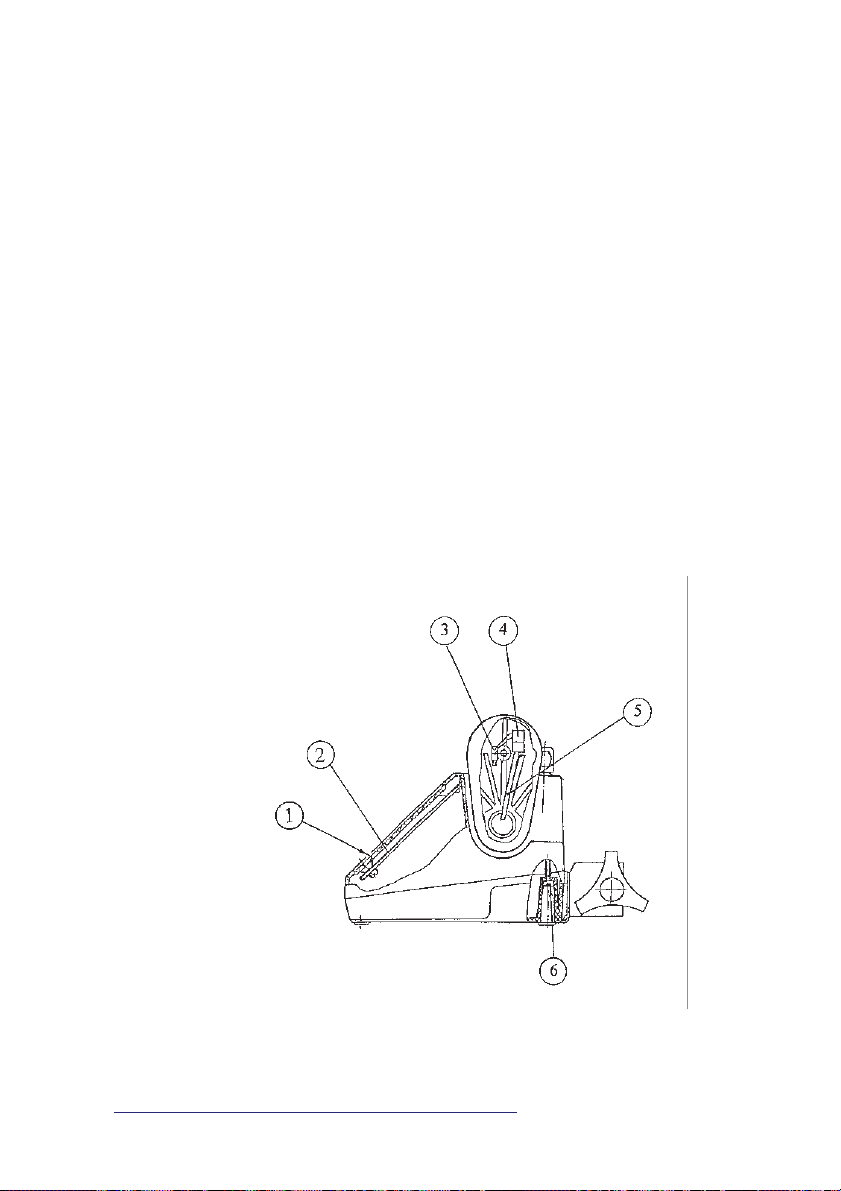
10.13. REPLACING POWER SUPPLY INLET
(FIG. 2)
Disassemble the pump according to the section 10.1.
Unsolder wires from power supply inlet (1). Remove two
screws (2) and remove the power supply inlet (1). Install
the new power supply inlet (1) and re-solder wires to it
executing above-described actions in reverse order. Push
insulating tubes onto soldering places. Re-assemble the
pump in reverse order to section 10.1.
10.14. REPLACING SUPPLY UNIT
(FIG. 2)
u Disassemble the pump according to the section 10.1.
Disconnect connectors P13, P14 (11) and P11, P12 (6)
from supply unit (7). Remove four screws (10). Remove
the supply unit (7). Install the new supply unit (7) and
re-connect connectors executing above-described actions
in reverse order. Re-assemble the pump in reverse order
to section 10.1.
Fig.1
1. Keyboard
2. Electronic board B7043
3. Syringe sensor *
4. Connector *
5. Flexible cable *
6. Screws M4
36
SP-12S Pro, SEP-12S Plus and SEP-10S Plus syringe infusion pumps
* – optional
Page 37
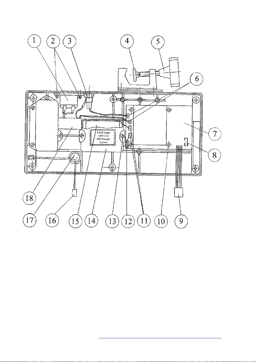
Fig.2
1. Power supply inlet 10. Screws ∅ 3x6,5
2. Screw M3x10 with nuts M3 11. Battery connector
3. Fuse unit with fuse T80mA 12. Battery fuse
4. Plastic cap 13. Screw ∅ 3x10
5. Cross knob 14. Cover
6. Mains connector 15. Battery
7. Supply unit 16. Buzzer connector
8. Fuse T1A 17. Buzzer
9. Supply unit connector 18. Filter unit
Service manual
37
Page 38
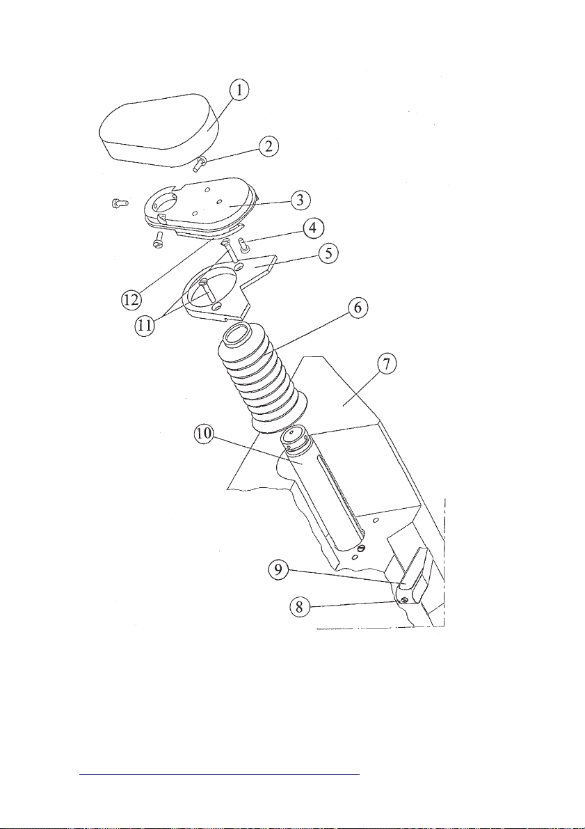
Fig.3
1. Cover 7. Housing
2. Screw M3x8 8. Screw M2,5x12
3. Plate 172 9. Syringe clamp
4. Screw ∅ 3x10 10. Tube
5. Support 11. Screws M3x16
6. Rubber bellows 12. Plate 146
38
SP-12S Pro, SEP-12S Plus and SEP-10S Plus syringe infusion pumps
Page 39
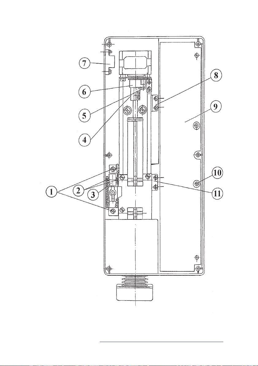
Fig.4
1. Screw M4x8
2. Screw M3x10
3. Syringe size sensor
4. Coupling
5. Screw M3x8
6. Optical sensor
7. MFC
8. Prealarm switch S2
9. Electronic board B7043
10. Screws ∅ 3x6,5
11. End switch S1
39
Service manual
Page 40
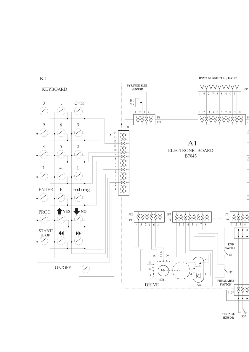
ANNEX A
ELECTRICAL SCHEMATIC DIAGRAM
OF THE PUMPS SP-12S Pro and SEP-12S Plus
40
SP-12S Pro, SEP-12S Plus and SEP-10S Plus syringe infusion pumps
Page 41
*
*
Service manual
* – optional
41
Page 42
ANNEX B
ELECTRICAL SCHEMATIC DIAGRAM
OF THE PUMP SEP-10S Plus
42
SP-12S Pro, SEP-12S Plus and SEP-10S Plus syringe infusion pumps
Page 43
Service manual
* – optional
43
Page 44
ANNEX C
INTERCONNECTION
DIAGRAM
OF THE PUMPS
44
SP-12S Pro, SEP-12S Plus and SEP-10S Plus syringe infusion pumps
Page 45
Service manual
* – optional
45
Page 46
ANNEX D
ELECTRICAL SCHEMATIC DIAGRAM OF
ELECTRONIC BOARD B7043
46
SP-12S Pro, SEP-12S Plus and SEP-10S Plus syringe infusion pumps
Page 47
Service manual
47
Page 48
ANNEX D
ELECTRICAL SCHEMATIC DIAGRAM OF
ELECTRONIC BOARD B7043 (continue)
48
SP-12S Pro, SEP-12S Plus and SEP-10S Plus syringe infusion pumps
Page 49
Service manual
49
Page 50
ANNEX D
ELECTRICAL SCHEMATIC DIAGRAM OF
ELECTRONIC BOARD B7043 (continue)
50
SP-12S Pro, SEP-12S Plus and SEP-10S Plus syringe infusion pumps
Page 51
Service manual
51
Page 52
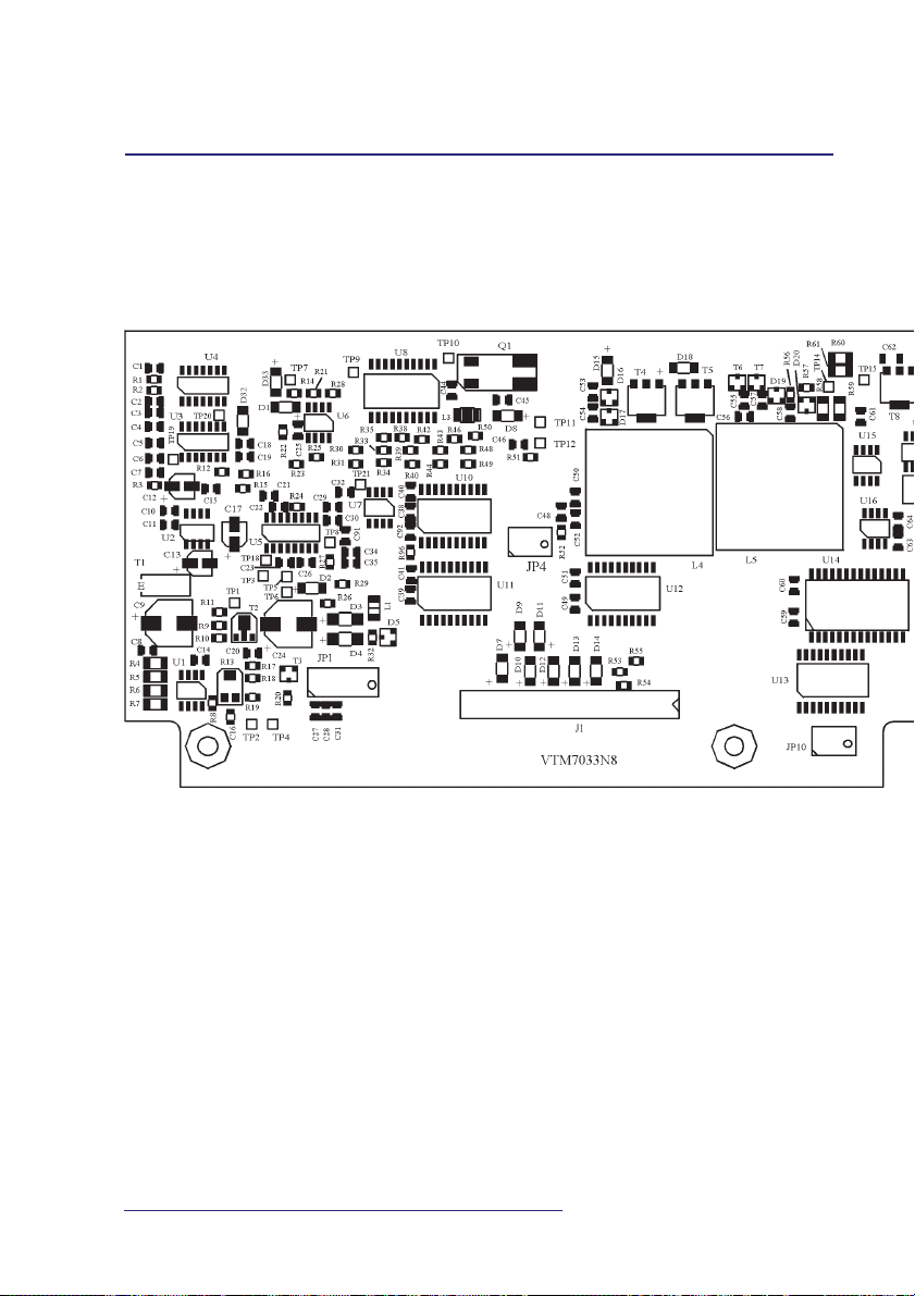
ANNEX E
ASSEMBLY DRAWING OF ELECTRONIC BOARD B7043
52
SP-12S Pro, SEP-12S Plus and SEP-10S Plus syringe infusion pumps
Page 53
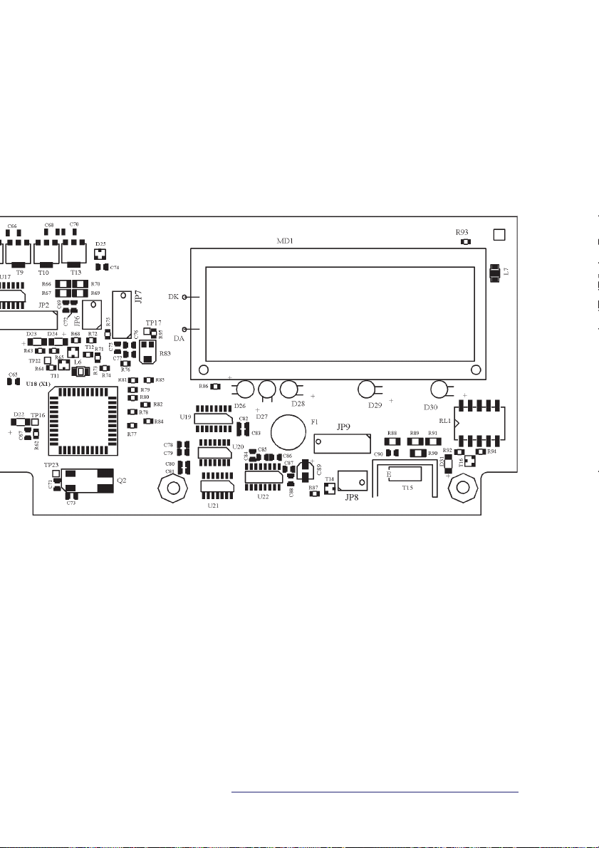
Service manual
* – optional
53
Page 54
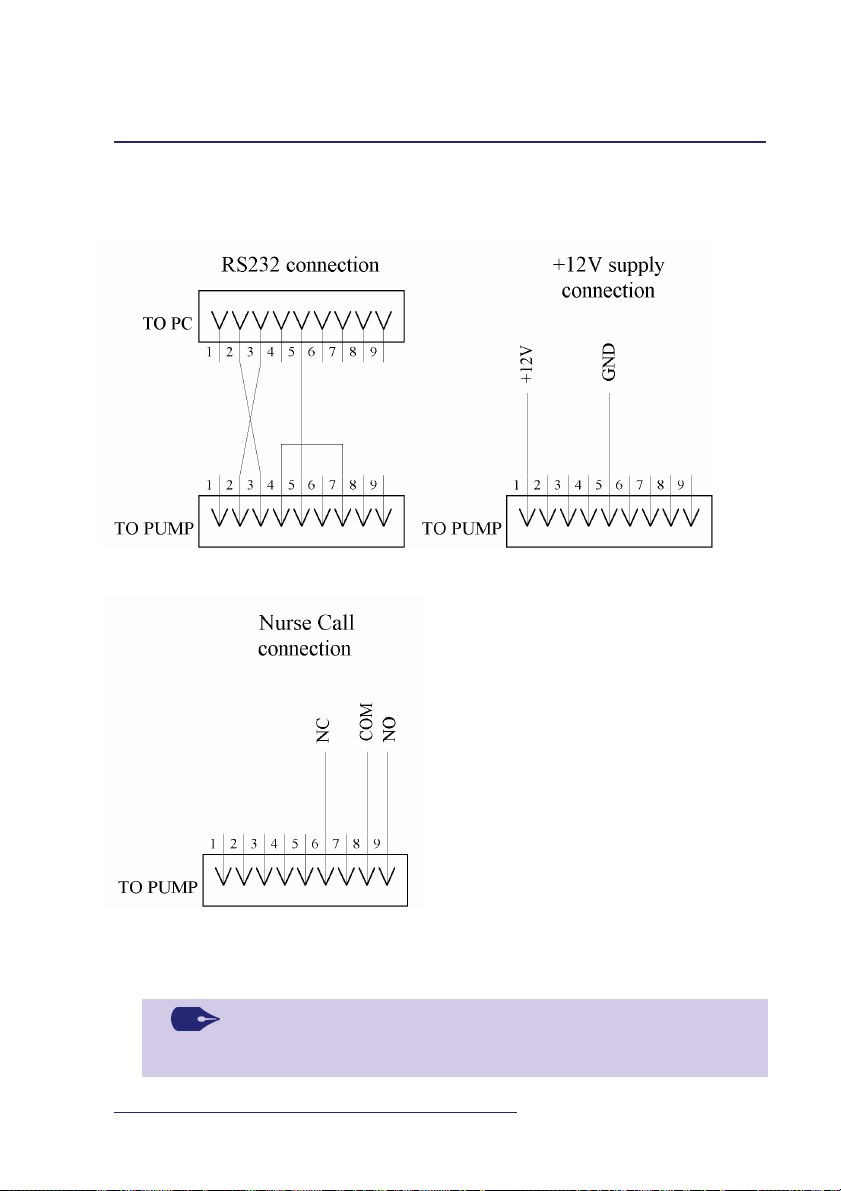
ANNEX F
DRAWING OF CABLES FOR MULTIFUNCTIONAL
CONNECTOR (MFC)*
NOTE:
Use standard D Type — 9 pin connectors.
54
SP-12S Pro, SEP-12S Plus and SEP-10S Plus syringe infusion pumps
Connection data:
Ground (GND)
Normally Closed (NC)
Common (COM)
Normally Open (NO)
* – optional
Page 55

ANNEX G
DESCRIPTION OF ERRORS
All errors are listed in the Table:
Error
ERROR 001
ERROR 002
ERROR 004
ERROR 005
ERROR 006
ERROR 007
ERROR 008
ERROR 009
ERROR 011
ERROR 013
ERROR 016
ERROR 017
ERROR 018
ERROR 019
DESCRIPTION
Cannot read data from external EEPROM
Cannot write data to internal EEPROM
Occlusion koeff. settings failed
Language setting failed
Incorrect program CRC
Syringe size sensor calibration failed
Date and time setting failed
Drug set failed
Incorrect external EEPROM CRC
Watchdog activated
Data of current syringe failed
SRAM test failed
Incorrect program CRC (fast test)
Incorrect Bootloader CRC
CORRECTIVE
ACTIONS
Recycle power
Configure Setup menu
repeatedly (see Chapter 6)
Calibrate occlusion level
(see Chapter 6)
Select language
(see Chapter 6)
Consult the manufacturer
Calibrate syringe size
sensor (see Chapter 6)
Set date and time
(see Chapter 6)
Restore default drug set
(see Chapter 6)
Consult the manufacturer
Consult the manufacturer
Recycle power
Recycle power
Consult the manufacturer
Consult the manufacturer
NOTE:
When eliminated fault repeats consult the manufacturer.
Service manual
55
Page 56

ANNEX H
PREVENTIVE MAINTENANCE CHECKLIST
Serial number ...............
Service
Manual Parameter Value
section
7.2 Infusion volume accuracy %
7.3 Infusion rate accuracy %
7.4 Bolus volume accuracy %
7.5 Occlusion pressure accuracy: Low kPa
Service
Manual Alarm signal Comment
section
8(1) OCCLUSION!!!
8(2) OCCLUSION or END
8(3) NO MAINS!!! Check power cord
8(4) LOW BATTERY
8(5) VERY LOW BATTERY
8(6) X min. PREALARM!
8(7) END of INFUSION
8(8) KOR X.X ml/h
8(9) SYRINGE EMPTY!
8(10) CLAMP OPENED!
8(11) ILLEGAL SYRINGE! Change SYRINGE!
8(13) ATTENTION! 2 min INACTIVE
8(14) STANDBY TIME ELAPSED
Med kPa
High kPa
Pump owner/ward ......................................................................................................
Tests performed by (name, surname, signature) ............................................................
Tests performed (date) ................................................................................................
56
SP-12S Pro, SEP-12S Plus and SEP-10S Plus syringe infusion pumps
Page 57

ANNEX I
COMPONENT LIST
No Description Code
1
2
3
4
5
6
7
8
9
10
11
12
13
14
15
16
17
18
19
20
21
22
23
24
25
Battery GB1, GB2
Rubber bellows
Optical sensor TAX1
End S1 and prealarm S2 switch
Syringe sensor S3
Electronic board B7043
Keyboard
Microcontroller U18
Syringe size sensor
Buzzer unit Z1
Power supply inlet
Supply unit
Fuse T80 mA F1
Fuse T160 mA F1
Fuse T1A F1, F2(A2)
Plastic cap
Filter unit
Cross knob
Display MD1
LED yellow D26, D27, D28
LED green D29, D30
Mains cable
Syringe clamp
Plate 172
Plate 146
Support
Service manual
B6640004
B8703002
V5440101
V5500900
B6660016
B3087043
V6675033 (for SEP-10S Plus)
V6675034 (for SP-12S Pro)
V6675042 (for SEP-12S Plus)
B6270010
B6666002
B6710005 (with volume control)
B6710006 (without volume control)
V5520180
B6340011
V5501002 (for 230 VAC mains)
V5501000 (for 115 VAC mains)
V5501020
B8123009
B6730006
B6370007
V5500442
V5430100
V5430200
V5570010 (European style)
B8127002
B8600172
B8600146
B8126028 (without tooth)
B8126046 (with tooth)
57
Page 58

ANNEX J
ACCESSORIES
Part number Description
B8640027 Spacer syringe sizing 1
B8640027-01 Spacer syringe sizing 2
B8640027-02 Spacer syringe sizing 3
B8640027-03 Spacer syringe sizing 4
58
SP-12S Pro, SEP-12S Plus and SEP-10S Plus syringe infusion pumps
Page 59

ANNEX K
COMMUNICATION PROTOCOL
TECHNICAL DESCRIPTION
u Communication protocol is used for downloading „Event
Log” from the syringe pump in response to commands
from a computer.
u The protocol uses a variation of the HDLC format for
data transfer. Following format is used to transfer commands from computer to the syringe pump:
BYTES CODE DESCRIPTION
1 0xC0 Flag
1 0x02 —
1 0x13 Control
1 0x00 Status (reserved)
1 — Command code (see below)
1 0x00 —
2 — CRC
1 0xC1 Flag
u Following commands are used for downloading „Event
Log” from syringe pump to computer:
CODE DESCRIPTION
0x01 Send Model and SN
0x30 Send Event Log Size
0x31 Send (repeat) frame
0x32 Send next frame
0x33 Quit
u Following format is used for transferring data from sy-
ringe pump to computer:
BYTES CODE DESCRIPTION
1 0xC0 Flag
1 0x03 —
1 0x13 Control
1 0x00 Status (reserved)
1 — Code of command from PC pump is responding to
1 0x00 —
45 — Data (5 events)
2 — CRC
1 0xC1 Flag
Service manual
59
Page 60

u Technical specification of the RS232 Interface is shown
in the 1 table
1 table
RS 232 Specification
Connector 9-pin D-Socket
TX Pin 3
RX Pin 2
Baud rate 9600 baud
Bit format 1 start, 8 data, no parity, 1 stop
Character format Binary/ASCII (see below)
Ground Pin 5
Isolation socket/pump 4 kV, Air Gap ±15kV, Contact ±8kV
NOTE:
ASCII is used to transfer information regarding pump
model in response to command „Send Model and SN”
u Cable connections scheme is shown in 2 table
2 table
PC Pump
Pin 3 (Tx) Pin 2 (Rx)
Pin 2 (Rx) Pin 3 (Tx)
Pin 5 (Ground) Pin 5 (GND)
Pin 4 Nc Pin 4, Pin 7 (Jumper)
Pin 7 Nc
60
SP-12S Pro, SEP-12S Plus and SEP-10S Plus syringe infusion pumps
 Loading...