

Page 1

N701-AT User’s Guide rev0D
N701-AT User’s Guide
(Quad band GSM/GPRS modem module)
N701-AT User’s Guide
Page 1 of 8
Page 2
N701-AT User’s Guide rev0D
N701-AT User’s Guide
Notice
Congratulations on choosing the N701-AT Quad Band GSM/GPRS modem
module.
Please read this User Guide thoroughly before use of N701-AT so that you
understand all of the features and functions.
Please note that use of unauthorized accessories and interfacing could cause
harm to you, your N701-AT or both and will void the warranty. Only use the
module in a way of AISA Tech User’s Guide and technical manual specifies.
AISA Tech reserves the right to make changes and improvements to any of
the products or accessories described in this guide without prior notice.
note) Some service providers do not support all of the functions described in
this User Manual. See additional documentation from your service privider.
Security
If your module or a model uses the module is lost or stolen, you must report it
to your network operator or service provider so that they can restrict the
module and model from use.
This is important, as you may be liable for the cost of unauthorized calls and
SMS, data transactions until the equipment is restricted.
You can help prevent such mobile phone crime by taking the following precautions:
- Don’t leave your module or model visible in a vehicle when you leave it.
- Make a note of the IMEI number. This number will be found on the bottom
side of the AVL.
Safety
Personal
- FCC regulations limit exposure to radio frequency (RF) radiation. To comply
with these regulations, operators of this device must maintain a distance of at
20 cm from the antenna. While the device is on, the
least
operator’s body and parts of the body such as eyes, hands, or head, must be
cm.or farther from the antenna .
- Operation of any radio equipment including N701-AT module and a model
uses it may interfere with the function of inadequately shielded medical
devices such as hearing aids and pacemakers. You must consult the
manufacturer of these devices or your physician, before use.
- Do not switch on your N701-AT in hospitals unless in areas where it is
clearly marked to do so. N701-AT continue to transmit call responses even if
left in stand-by mode. You must switch off when requested to do so.
- Do not move the antenna close to, or it to touch any exposed part of the
body when the N701-AT is turned power on; a damaged antenna may cause a
minor burn.
20
Page 2 of 8
Page 3
N701-AT User’s Guide rev0D
N701-AT User’s Guide
N701-AT Use
- Your N701-AT module produces magnetic fields. Do not place next to
magnetic storage media such as computer diskettes or credit cards when it is
powered on.
- Operating your N701-AT module close to other electrical equipment such as
televisions, phones, radios and personal computers, may cause interference.
Once again, please turn you N701-AT power off when entering a Hospital;
Medical Equipment can be affected.
- Do not expose N701-AT module to strong sunlight, direct heat or liquids
(such as water and solvent).
- Do not expose your N701-AT module to strong ESD (Electro Static
Discharge) since the ESD could result incorrect behavior of the N701-AT
module.
On the Road
- Before making or receiving calls, acquaint you thoroughly with the applicable
local laws and guidelines regarding the use of mobile radio device and
telephones and observe them at all times.
- Air safety bags, anti-lock brakes, speed control and fuel injection systems
are normally immune to radio transmissions but if you experience problems,
consult your vehicle dealer.
- Turn off you N701-AT module when refueling or where there are signs
restricting the use of 2-way radio equipment. Do not store or carry
flammable or explosive materials in the same compartment as your N701-AT
module.
Inside Aircraft
- Switch off your N701-AT module when in an aircraft. The use of
GSM/GPRS module/model in an aircraft may be dangerous to the operation of
the aircraft, disrupt the cellular network and is illegal.
Page 3 of 8
Page 4
N701-AT User’s Guide rev0D
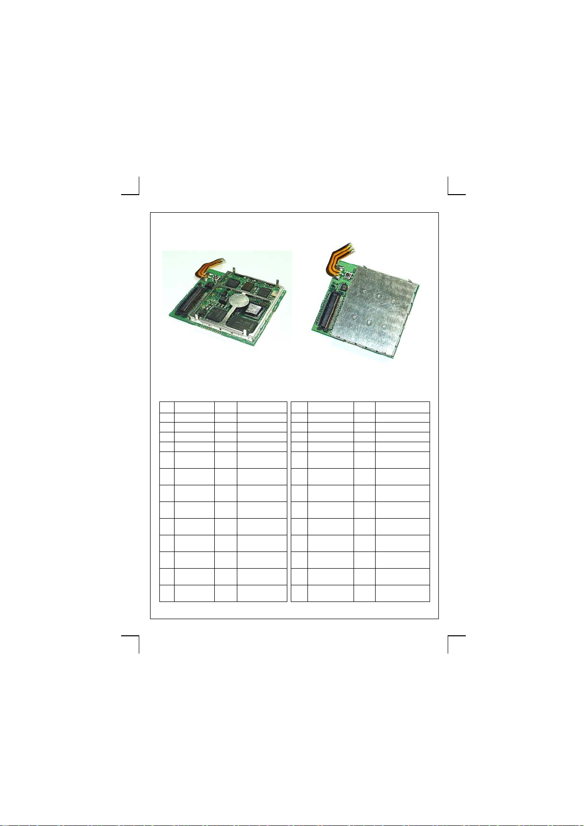
Product overview,
The N701-AT composed of following interfaces.
*size : 33.5 x 37.5 x 3.9mm
- N701-AT interface ports and indicators -
Pin Description Type Remark Pin Description Type Remark
1 VBAT Power +3.4~4.0 Volts 2 GND GND Ground
3 VBAT Power +3.4~4.0 Volts 4 GND GND Ground
5 VBAT Power +3.4~4.0 Volts 6 GND GND Ground
7 VBAT Power +3.4~4.0 Volts 8 GND GND Ground
9 VCHARGE CHG +5~6 Volts
11 VCHARGE CHG +5~6 Volts
10 DCD I UART0
12 DTR 1 UART0
N701-AT User’s Guide
13 SIM_VCC VCC +2.85 Volts
15 SIM_IO I/O SIM I/O 16 RTS_0 O UART0
17 SIM_CLK O SIM Clock 18 RXD_0 I UART0
19 SIM_RST O SIM reset 20 TXD_0 O UART0
21 MRSTO - JTAG signal 22 RI O Ring Indicator
23 MTSRO - JTAG signal 24 DSR I UART0
25 SCLK0 O SPI clock line 26 RXD_1 I UART1
14 CTS_0 I UART0
Page 4 of 8
Page 5
N701-AT User’s Guide rev0D
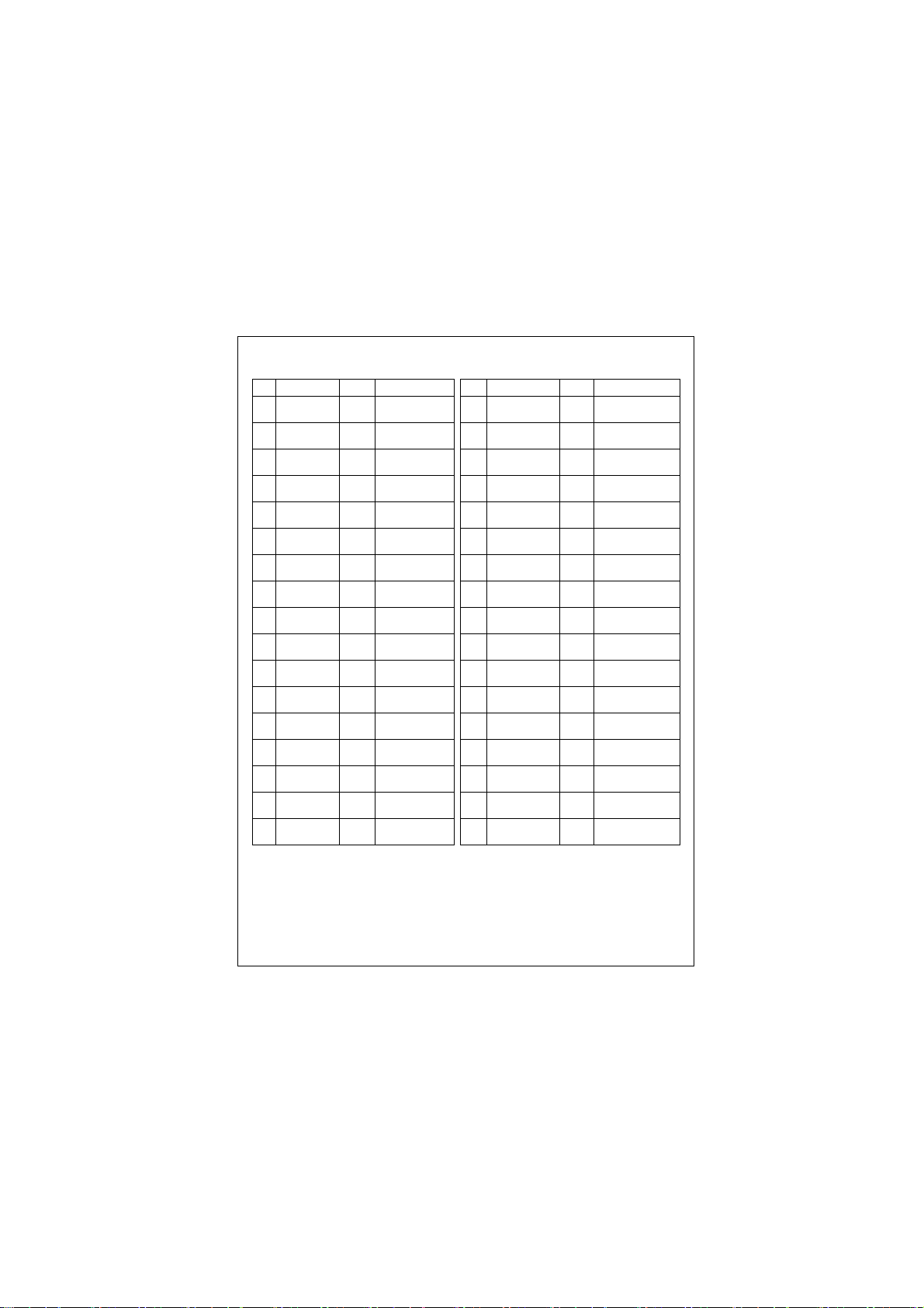
- N701-AT interface ports and indicators – continued.
Pin Description Type Remark Pin Description Type Remark
27 SCL O I2C clock line 28 TXD_1 O UART1
29 SDA I/O I2C data line 30 KEYOUT0 O Key matrix
31 CKL0_DAI - DAI signal 32 KEYOUT1 O Key matrix
33 RXD_DAI - DAI signal 34 KEYOUT2 O Key matrix
35 TXD_DAI - DAI signal 36 KEYOUT3 O Key matrix
37 WA0_DAI - DAI signal 38 KEYOUT4 O Key matrix
39 EXTRSTN I System reset
40 KEYOUT5 O Key matrix
N701-AT User’s Guide
41 MICP1 Audio Mic 1 input
43 MICN1 Audio Mic 1 input
45 EPPA1B Audio Earpiece
47 EPPA2A Audio Earpiece
49 MICP2 Audio Mic 2 input, -50 CAP19 I/O GPIO
51 MICN2 Audio Mic 2 input, -52 CAP02 I/O GPIO
53 AUOP Audio Loud speaker
55 AUON Audio Loud speaker
57 ADC1 AI A/D converter
59 ADC2 AI A/D converter
-
-
42 KEYIN0 I Key matrix
44 KEYIN1 I Key matrix
46 KEYIN2 I Key matrix
48 KEYIN3 I Key matrix
54 CAP05 I/O GPIO
56 CAP06 I/O GPIO
58 CAP00 I/O GPIO(Interrupt
60 CAP22 I/O Headset detection
***Antenna port of the N701-AT module form a Coplanner strip line, for other
types of antenna connector such as MMCX female, please consult with your
N701-AT supplier.
***FCC regulations limit exposure to radio frequency (RF) radiation, To comply
with these regulation, an antenna to be used with the N701-AT GSM/GPRS
modem module shall be remain an antenna gain of not greater than 0dBi.
Page 5 of 8
Page 6
N701-AT User’s Guide rev0D
N701-AT User’s Guide
Introduction.
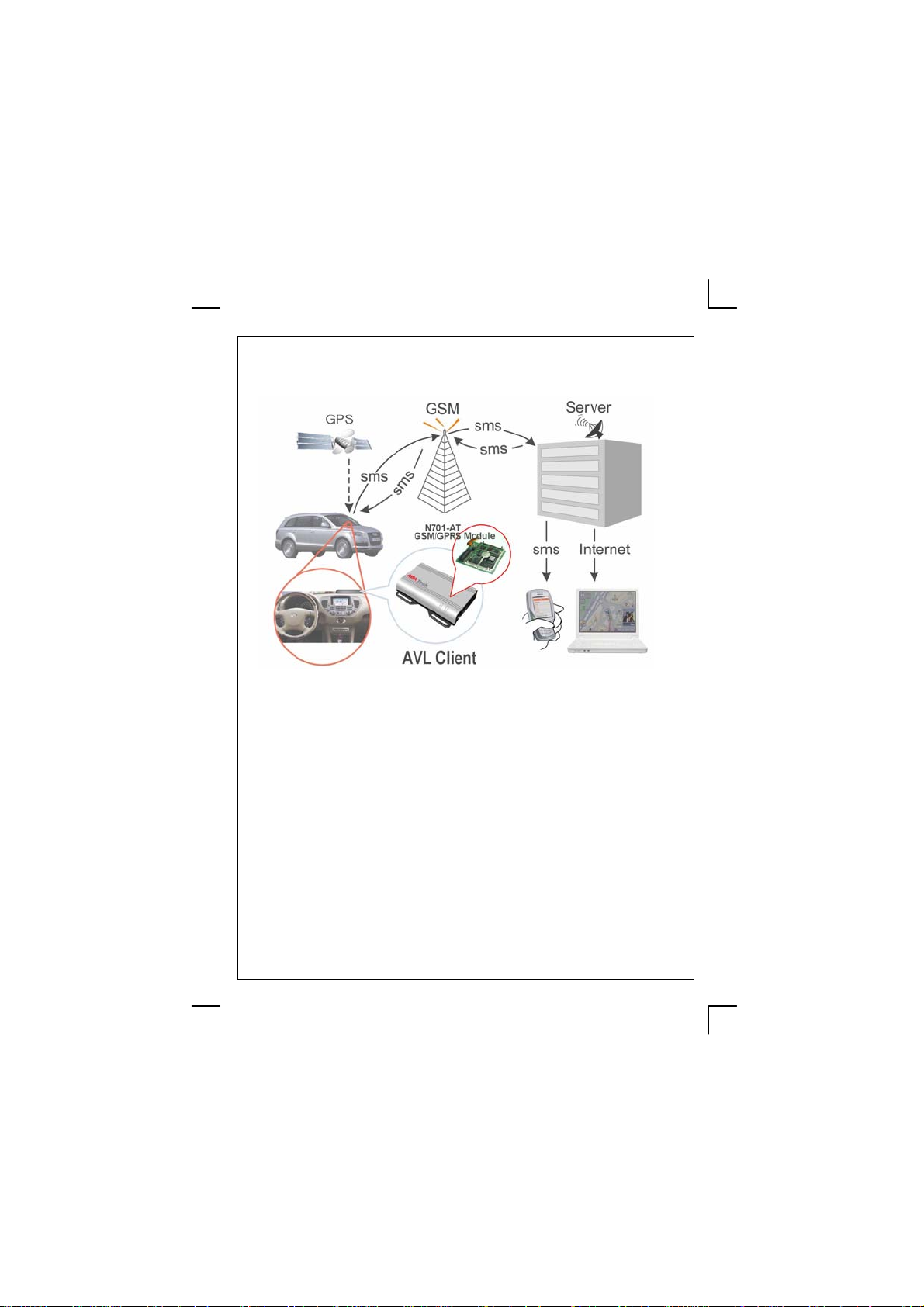
Your N701-AT AVL is a GSM/GPRS based device that interact with a sever to
remotely collect vehicle navigational information. – see also picture 1 below –
- Picture 1 -
Features :
- Quad band GSM/GPRS.class 8
- GPRS Class B mobile station
- support SMS and TCP/IP
- Integrated GPS receiver.
- Built in GSM/GPRS antenna.
- support 1.8V and 3V SIM interface.
- 3.4 ~ 4.0 Volts of supply voltage.
- 4 GPIO, 4x6 Keypad matrix.
- 2 A/D converter inputs.
- 1 high speed SPI output.
- UART0 with CTS/RTS flow control speed at 115200 bps.
- UART1 without flow control.
- I2C interface
- 2 Sets of Microphone inputs and earpiece outputs.
- 1 loud speaker output
Page 6 of 8
Page 7
N701-AT User’s Guide rev0D
N701-AT User’s Guide
Basic operation
Your N701-AT support GSM07.07(ETSI TS 100 916) and GSM07.05(ETSI TS
100 585) compatible quad band GSM/GPRS module with following proprietary
AT commands.
For more details of applicable AT commands and AT commands descriptions,
please refer to GSM07.07(ETSI TS 100 916) and GSM07.05(ETSI TS 100
585) Technical specification for detail.
-N701-AT proprietary AT commands.
a) AT+CPWROFF : power off the module.
b) AT+CGDATA=[<L2P>,[<cid>,[<cid>[….]]]] : Enter data state.
Command Possible responses
AT+CGDATA=”PPP”,1 CONNECT
Test command
AT+CGDATA=?
Note: Possible are protocols : “PPP”, “M-HEX”, “M-RAW-IP”. After entering
AT+CGDATA=”M-Hex”,1
the protocol can be used as follows:
Syntax : <int: counter><int: length[1-1500]><hex-sequence>[0-9-fA-F]
Examples:
- 1 200<CR> - send 1 packet with 200 0x2B (fill character)
- 5 1000<CR> - send 5 packets with 1000 0x2B (fill character)
- 1 5 31 32 33 34 35<CR> - send 1 packet with the given contents
- 1 10 31<q><CR> - send 1 packet with 10 0x31
Either a packet is sent
- if the length field is terminated with <CR>
- or the length value is equal to # chars of hex-sequence
- or the input is terminated with a character not equal to hex digit or <CR>
The session is terminated by default with +++, the context is deactivated.
If ct108 (AT&D) is equal to 2 and the selected L2 protocol is “M-HEX”, the channel is
switched back to idle mode but the context remains activated. Leave the layer 2
packet protocol by typing of +++.
It follows data transfer
or
CME ERROR:<error>
+CGDATA:”PPP”
i.e. +CGDATA(list of supported<L2P>s)
OK
Page 7 of 8
Page 8
N701-AT User’s Guide rev0D
N701-AT User’s Guide
Trouble shooting.
Your N701-AT AVL has no use r accessible parts inside and open up the cover
could result ham to user.
Bring authorized service person through your dealer for service.
1053-20 Namhyun-don, Gwanak-gu,
Phone : +82-(0)2-3474-6744
Page 8 of 8
AISA Tech Co., Ltd.
Seoul 151-802 Koea
Fax : +82-(0)2-3474-6746
 Loading...