


EDS Series
Indoor Units Outdoor Units
EDS25 GCN9
EDS35 GCN12
EDS52 ONG3-18
EDS73 GCZ22
EDS100 GC10-34
EDS120 GC45
EDS25X2 GC9+9
EDS35X2 GC12+12
EDS52X2 GC17+17
EDS25X2+EDS35 GC9+9+12
EDS25X2+EDS52 GC9+9+17
EDS25+EDS35+EDS52 GC9+12+17
EDS35X3 GC12+12+12
REFRIGERANT
R22
COOLING ONLY
COOLINGONLYWITHHEATER
HEAT PUMP
HEAT PUMP WITH HEATER
REV: 0 FEB 2009

A
LIST OF EFFECTIVE PAGES
Revision 0
Service Manual - EDS
LIST OF EFFECTIVE PAGES
Note: Changes in the pages are indicated by a “Revision#” in the footer of each effected page
(when none indicates no changes in the relevant page). All pages in the following list represent
effected/ non effected pages divided by chapters.
Dates of issue for original and changed pages are:
Original ....... 1 ........ FEB 2009
Total number of pages in this publication is 137 consisting of the following:
Page
No.
Revision
No. #
Page
No.
Revision
No. #
Page
No.
Revision
No. #
Title....................... 0
A ........................... 0
i............................. 0
1-1 - 1-3 ................ 0
2-1 - 2-6 ................ 0
3-1 ........................ 0
4-1 - 4-4 ................ 0
5-1 - 5-12 .............. 0
6-1 - 6-6 ................ 0
7-2 ........................ 0
8-1 - 8-6 ................ 0
9-1 - 9-4........................ 0
10-1-10-2 .............. 0
11-1....................... 0
12-1-12-31 ............ 0
13-1-13-2 .............. 0
14-1-14-24 ............ 0
Installation manual
.0
=HURLQWKLVFROXPQLQGLFDWHVDQRULJLQDOSDJH
*Due to constant improvements please note that the data on thisVHUYLFHPDQXDOFDQEHPRGL¿HGZLWKRXWQRWLFH
**Photos are not contractual

i
TABLE OF CONTENTS
Revision Y07-00Service Manual - EDS
Table of Contents
1. INTRODUCTION ...................................................................................................1-1
2. PRODUCT DATA SHEET......................................................................................2-1
3. RATING CONDITIONS ..........................................................................................3-1
4. OUTLINE DIMENSIONS .......................................................................................4-1
5. PERFORMANCE DATA & PRESSURE CURVES ................................................5-1
6. SOUND LEVEL CHARACTERISTICS ..................................................................6-1
7. ELECTRICAL DATA..............................................................................................7-1
8. WIRING DIAGRAMS .............................................................................................8-1
9. ELECTRICAL CONNECTIONS.............................................................................9-1
10. REFRIGERATION DIAGRAMS.............................................................................10-1
11. TUBING CONNECTIONS......................................................................................11-1
12. CONTROL SYSTEM .............................................................................................12-1
13. TROUBLESHOOTING ..........................................................................................13-1
14. EXPLODED VIEWS AND SPARE PARTS LISTS.................................................14-1
15.
INSTALLATION MANUAL
..................
................................................................15-1

1-1
INTRODUCTION
Revision 0Service Manual - EDS
1. INTRODUCTION
1.1 General
The new EDS ductable pressurized system basic on comapct indoor and outdoor unit, it range
comprise the A (cooling only) ,B(cooling only with supplementart heater) ,H (heat pump) ,D(heat
pump with supplementare heater),Dual and Trio, models as follows:
Cooling Only:
EDS25A/GCN9 R22 ST; EDS35A/GCN12 R22 ST;EDS52A/ONG3-17 R22 ST;
EDS73A/GCZ R22 ST; EDS100A/GC10-34 R22 ST;EDS120A/GC45 R22 ST;
EDS25A/GCN9 R22 ST; EDS35A/GCN12 R22 ST;EDS52A/ONG3-17 R22 ST;
EDS73A/GCZ R22 ST; EDS100A/GC10-34 R22 ST;EDS120A/GC45 R22 ST;
Cooling Only with supplementary heater:
1.2 Main Features
The EDS VHULHVEHQH¿WVIURPWKHPRVWDGYDQFHGWHFKQRORJLFDOLQQRYDWLRQs,
namely:
R22 models.
Microprocessor control.
Infrared remote control with liquid crystal display.
Supports Indoor Air Quality features, such as –.
,QGRRUODUJHGLDPHWHUFURVVÀRZIDQ, allowing low noise level operation.
Bended indoor coil with treated alumLQXP¿QVDQGFRDWLQJIRULPSURYHGHI¿FLHQFy.
Easy access to the interconnecting tubing and wiring connections, so that removing
the front grill or casing is not necessary.
Refrigerant pipes can be connected to the indoor unit from 5 different optional
directions.
Low indoor and outdoor noise levels.
Easy installation and service.
New package design for indoor unit, it should be based on open sleeve and open
sides
Installation manual to be printed on one page with back and front printing
One RC simply manual printing on two side as the standard
EDS25H/GCN9 R22 RC; EDS35H/GCN12 R22 RC;EDS52H/ONG3-17 R22 RC;
EDS73H/GCZ R22 RC; EDS100H/GC10-34 R22 RC;EDS120H/GC45 R22 RC;
Heat pump:
EDS25D/GCN9 R22 RC; EDS35D/GCN12 R22 RC;EDS52D/ONG3-17 R22 RC;
EDS73D/GCZ R22 RC; EDS100D/GC10-34 R22 RC;EDS120D/GC45 R22 RC;
Heat pump with supplementary heater:
EDS25x2 A(B,D,H)/GC9+9 ST(RC); EDS35x2 A(B,D,H)/GC12+12 ST(RC);
EDS52x2 A(B,D,H)/GC17+17 ST(RC);
Dual:
EDS25x2+35A(B,D,H)/GC9+9+12 ST(RC);EDS25x2+52A(B,D,H)/GC9+9+17 ST(RC);
EDS25+35+52A(B,D,H)/GC9+12+17 ST(RC);EDS35x3A(B,D,H)/GC12+12+12 ST(RC)
Trio:

1-2
INTRODUCTION
Revision 0 Service Manual - EDS
1.3 Indoor Unit
The indoor unit is ductable pressurized VSOLWV\VWHPDQGFDQEHHDVLO\¿WWHGWRPDQ\W\SHVRI
residential and commercials applications.
It includes:
Casing with air inlet and outlet grills.
AODUJHGLDPHWHUWDQJHQWLDOIDQ
Bended coil with treated aluminum ¿ns.
0RWRUL]HGÀDSV
Multi-speed motor with internal protection
Advanced electronic control box assembly
Interconnecting wiring terminal block
Mounting plate
1.4 Filtration
The EDS VHULHVSUHVHQWVRQO\RQHW\SHRIDLU¿OWHUV
Easily accessible, and re-usable pre¿OWHUVPHVK
1.5 Control
The microprocessor indoor controller, and wire controller with remote controller, supplied as
VWDQGDUGSURYLGHFRPSOHWHRSHUDWLQJIuQFWLRQDQGSURJUDPPLQJ)RUIXUWKHUGHWDLOV
SOHDVHUHIHUWRWKH2SHUDWLRQ0DQXDO Appendix A.
1.6 Outdoor Unit
The EDS outdoor units can be insWDOOHGDVÀRRURUZDOOPRXQWHGXQLWVE\XVLQJD
wall supporting bracket. The metal sheets are protected by anti- corrosion paint work
DOORZLQJORQJOLIHUHVLVWDQFH All outdoor XQLWVDUHSUHFKDUJHG)RUIXUWKHULQIRUPDWLRQ
SOHDVHUHIHUWRWKH3URGXFW'DWD6KHHW, Chapter 2.
It includes :
Compressor mounted in a soundprooIHGFRPSDUWPHQW
Rotary –IRU*&15675&*&15675&21*5675&*&=5675&
Scroll –IRU*&5675&*&5675&
$[LDOIDQ
2XWGRRUFRLOZLWKK\GURSKLOLFORXYHU¿nVIRU5&XQLWV
2XWOHWDLUIDQJULOO
Interconnecting wiring terminal block.

1-3
INTRODUCTION
Revision 0 Service Manual - EDS
1.7 Tubing Connections
Flare type interconnecting tubing to be produced on site.
For further details please refer to the Installation Manual, Outdoor Chapter 3.
1.8 Inbox Documentation
Each unit is supplied with its own installation and operation manuals, one simply
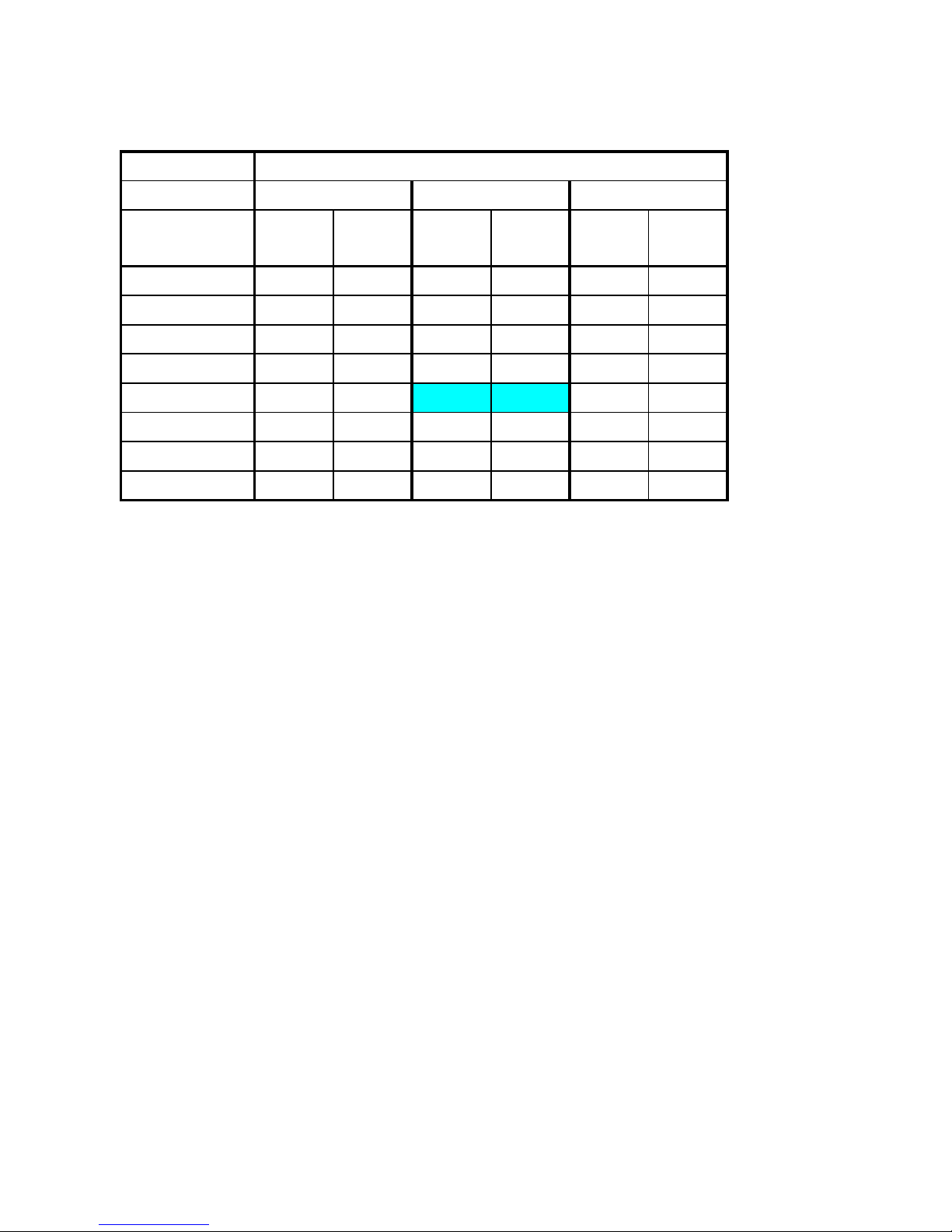
remote control manual Matching Table
Indoor unit
Type Outdoor unit
Unit 1 Unit 2 Unit 3
EDS25EDS35EDS
52
EDS73 EDS100 EDS120
GCN 9 EDS25 A/B
GCN 12 EDS35 A/C
ONG 3-18 EDS52 A/C
GCZ 22 EDS73 A/C
GC 10-34 EDS100 B/D
Single
GC 45 EDS120 B/E
GC9+9 EDS25 EDS25 A/B
GC12+12 EDS35 EDS35 A/C
Dual
GC17+17 EDS52 EDS52 A/C
GC9+9+12 EDS25 EDS25 EDS35 A/B A/C
GC9+9+17 EDS25 EDS25 EDS52 A/B A/C
GC9+12+17 EDS25 EDS35 EDS52 A/B A/C A/C
Trio
GC12+12+12 EDS35 EDS35 EDS35 A/C
1.9 Matching Table
1.9.1 R22
A-1/4’’ B-3/8’’ C-1/2’’ D-5/8’’ E-3/4’’ Liquid / Suction

Model Indoor Unit
EDS 25
Model Outdoor Unit GCN 9
Installation Method of Pipe Flared
Characteristics
Units Cooling only
Cooling Heating
Capacity (4)
Btu/hr 9380
9380 9550
kW 2.75
2.75 2.80
Power input (4)
kW 0.932
0.932 0.80
EER (Cooling) or COP(Heating) (4)
W/W 2.95
2.95 3.50
Energy efficiency class
C
CB
Power supply
V
220-240
Ph
1
Hz
50
Rated current
A 4.3
4.3 3.7
Power factor
0.95
0.95 0.95
Prated (IDU)
W
80
Prated (IDU+ODU)
W
1370
Starting current
A
18.2
Circuit breaker rating
A
10
INDOOR
Fan type & quantity DirectX1
Fan speeds
H/M/L RPM
1210/1020/860
Air flow (1)
H/M/L m3/hr
588/409/-
External static pressure
Min Pa
30Pa
Sound power level (2)
H/M/L dB(A)
59/54/50
Sound pressure level(3)
H/M/L dB(A)
46/41/37
Moisture removal
l/hr
0.58
Condenstate drain tube I.D
mm
19.05
Dimensions
WxHxD mm
690x250x611
Net Weight
kg
20
Package dimensions
WxHxD mm
820x280x628
Packaged weight
kg
23
Units per pallet
units
10
Stacking height
units
5 levels
OUTDOOR
Refrigerant control Capillary tube
Compressor type,model Rotary,Meizhi PH170G1C-4DZDE1
Fan type & quantity Propeller(direct) x 1
Fan speeds
H RPM
750
Air flow
H m3/hr
1370
Sound power level
H dB(A) 60
61
Sound pressure level(3)
H dB(A) 50.5
51.1
Dimensions
WxHxD mm
760x545x245
Net Weight
kg 30
30.5
Package dimensions
WxHxD mm
880x310x610
Packaged weight
kg 33
33.5
Units per pallet
Units
9
Stacking height
units
3 Levels
Refrigerant type R22
Standard charge
kg(4m)
0.83
Additional charge
4mİLinİ10m:0g/m; 10m<Linİ15m:+130g
Connections
between units
Liquid line
In.(mm)
1/4"(6.35)
Suction line
In.(mm)
3/8"(9.52)
Max.tubing length
m.
Max.15
Max.height difference
m.
Max.7
Operation control type Remote control
Heating elements (Option)
kW
Others
(1)Airflow in ducted units;at nominal external static pressure 30Pa.
(2)Sound power in ducted units is measured at air discharge.
(3)Sound pressure level measured at 1-meter distance from unit.
(4)Rating conditions in accordance to ISO 5151 and ISO 13253 (for ducted units).
(5)The declared value's tolerance is in accordance with EN14511.
PRODUCT DATA SHEET
2. PRODUCT DATA SHEET
2-1Revision 0Service Manual - EDS

Model Indoor Unit
EDS 35
Model Outdoor Unit GCN12
Installation Method of Pipe Flared
Characteristics
Units Cooling only
Cooling Heating
Capacity (4)
Btu/hr 12620
12620 12110
kW 3.70
3.70 3.55
Power input (4)
kW 1.175
1.175 0.98
EER (Cooling) or COP(Heating) (4)
W/W 3.15
3.15 3.62
Energy efficiency class
B
BA
Power supply
V
220-240
Ph
1
Hz
50
Rated current
A 5.4
5.4 4.5
Power factor
0.95
0.95 0.95
Prated (IDU)
W
90
Prated (IDU+ODU)
W
1660
Starting current
A
25
Circuit breaker rating
A
15
INDOOR
Fan type & quantity DirectX1
Fan speeds
H/M/L RPM
900/730/660
Air flow (1)
H/M/L m3/hr
830/500/-
External static pressure
Min Pa
30
Sound power level (2)
H/M/L dB(A)
59/55/51
Sound pressure level(3)
H/M/L dB(A)
46/42/38
Moisture removal
l/hr
0.6
Condenstate drain tube I.D
mm
19.05
Dimensions
WxHxD mm
945x250x611
Net Weight
kg
27
Package dimensions
WxHxD mm
1095x280x628
Packaged weight
kg
30
Units per pallet
units
5
Stacking height
units
5 levels
OUTDOOR
Refrigerant control Capillary tube
Compressor type,model Rotary,Sanyo C-RV212HC2CB
Fan type & quantity Propeller(direct) x 1
Fan speeds
H RPM
830
Air flow
H m3/hr
1500
Sound power level
H dB(A) 64
64.5
Sound pressure level(3)
H dB(A) 55
56
Dimensions
WxHxD mm
760x545x245
Net Weight
kg 33
33.5
Package dimensions
WxHxD mm
880x310x610
Packaged weight
kg 35.5
36
Units per pallet
Units
9
Stacking height
units
3 Levels
Refrigerant type R22
Standard charge
kg(4m)
0.99
Additional charge
4mİLinİ10m:0g/m; 10m<Linİ15m:+170g
Connections
between units
Liquid line
In.(mm)
1/4"(6.35)
Suction line
In.(mm)
1/2"(12.7)
Max.tubing length
m.
Max.15
Max.height difference
m.
Max.7
Operation control type Remote control
Heating elements (Option)
kW
Others
(1)Airflow in ducted units;at nominal external static pressure 30Pa.
(2)Sound power in ducted units is measured at air discharge.
(3)Sound pressure level measured at 1-meter distance from unit.
(4)Rating conditions in accordance to ISO 5151 and ISO 13253 (for ducted units).
(5)The declared value's tolerance is in accordance with EN14511.
PRODUCT DATA SHEET
2-2
Revision 0Service Manual - EDS

Model Indoor Unit
EDS 52
Model Outdoor Unit ONG3-17
Installation Method of Pipe Flared
Characteristics
Units Cooling only
Cooling Heating
Capacity (4)
Btu/hr 19790
19790 18940
kW 5.80
5.80 5.55
Power input (4)
kW 1.92
1.92 1.61
EER (Cooling) or COP(Heating) (4)
W/W 3.02
3.02 3.45
Energy efficiency class
B
BB
Power supply
V
220-240
Ph
1
Hz
50
Rated current
A 8.8
8.8 7.4
Power factor
0.95
0.95 0.95
Prated (IDU)
W
154
Prated (IDU+ODU)
W
2460
Starting current
A
46.8
Circuit breaker rating
A
15
INDOOR
Fan type & quantity DirectX1
Fan speeds
H/M/L RPM
1210/1038/986
Air flow (1)
H/M/L m3/hr
1100/805/706
External static pressure
Min Pa
30
Sound power level (2)
H/M/L dB(A)
64/60/58
Sound pressure level(3)
H/M/L dB(A)
51/47/45
Moisture removal
l/hr
1.32
Condenstate drain tube I.D
mm
19.05
Dimensions
WxHxD mm
1080X611X250
Net Weight
kg
29
Package dimensions
WxHxD mm
1165X628X280
Packaged weight
kg
33
Units per pallet
units
5
Stacking height
units
5 levels
OUTDOOR
Refrigerant control Capillary tube
Compressor type,model Rotary,Panasonic 2V34S225BUC
Fan type & quantity Propeller(direct) x 1
Fan speeds
H RPM
920
Air flow
H m3/hr
2160
Sound power level
H dB(A) 65
65
Sound pressure level(3)
H dB(A) 54
55
Dimensions
WxHxD mm
795x610x290
Net Weight
kg 43
44
Package dimensions
WxHxD mm
970x650x394
Packaged weight
kg 46
47
Units per pallet
Units
9
Stacking height
units
3 Levels
Refrigerant type R22
Standard charge
kg(7.5m)
1.45
Additional charge
4mİLinİ10m:0g; 10m<Linİ15m:+100g
Connections
between units
Liquid line
In.(mm)
1/4"(6.35)
Suction line
In.(mm)
1/2"(12.7)
Max.tubing length
m.
Max.15
Max.height difference
m.
Max.7
Operation control type Remote control
Heating elements (Option)
kW
Others
(1)Airflow in ducted units;at nominal external static pressure 30Pa.
(2)Sound power in ducted units is measured at air discharge.
(3)Sound pressure level measured at 1-meter distance from unit.
(4)Rating conditions in accordance to ISO 5151 and ISO 13253 (for ducted units).
(5)The declared value's tolerance is in accordance with EN14511.
PRODUCT DATA SHEET
2-3Revision 0Service Manual - EDS

Model Indoor Unit EDS 73
Model Outdoor Unit GC-22
Installation Method of Pipe Flared
Characteristics
Units Cooling only
Cooling Heating
Capacity (4)
Btu/hr 23710
23710 25250
kW 6.95
6.95 7.40
Power input (4)
kW 2.31
2.31 2.05
EER (Cooling) or COP(Heating) (4)
W/W 3.01
3.01 3.61
Energy efficiency class
B
BA
Power supply
V
220-240
Ph
1
Hz
50
Rated current
A 10.6
10.6 9.4
Power factor
0.95
0.95 0.95
Prated (IDU)
W
242
Prated (IDU+ODU)
W
3250
Starting current
A
52
Circuit breaker rating
A
20
INDOOR
Fan type & quantity DirectX1
Fan speeds
H/M/L RPM
1206/1079/967
Air flow (1)
H/M/L m3/hr
1350/1134/909
External static pressure
Min Pa
30
Sound power level (2)
H/M/L dB(A)
64/61/59
Sound pressure level(3)
H/M/L dB(A)
51/48/46
Moisture removal
l/hr
1.45
Condenstate drain tube I.D
mm
19.05
Dimensions
WxHxD mm
1365X611X250
Net Weight
kg
35
Package dimensions
WxHxD mm
1515X628X280
Packaged weight
kg
39
Units per pallet
units
5
Stacking height
units
5 levels
OUTDOOR
Refrigerant control Capillary tube
Compressor type,model Rotary,Panasonic,2V40S225AUA
Fan type & quantity Propeller(direct) x 1
Fan speeds
H RPM
850
Air flow
H m3/hr
2480
Sound power level
H dB(A)
70
Sound pressure level(3)
H dB(A)
59
Dimensions
WxHxD mm
846x690x302
Net Weight
kg 53
55.5
Package dimensions
WxHxD mm
990x770x430
Packaged weight
kg 56.5
59
Units per pallet
Units
6
Stacking height
units
2 levels
Refrigerant type R22
Standard charge
kg(7.5m)
2.05
Additional charge
4mİLİ10m:+0g 10m<Lİ15m:+280g
Connections
between units
Liquid line
In.(mm)
ĭ9.53(3/8")
Suction line
In.(mm)
ĭ15.88(5/8")
Max.tubing length
m.
Max.15
Max.height difference
m.
Max.7
Operation control type Remote control
Heating elements (Option)
kW
Others
(1)Airflow in ducted units;at nominal external static pressure 30Pa.
(2)Sound power in ducted units is measured at air discharge.
(3)Sound pressure level measured at 1-meter distance from unit.
(4)Rating conditions in accordance to ISO 5151 and ISO 13253 (for ducted units).
(5)The declared value's tolerance is in accordance with EN14511.
PRODUCT DATA SHEET
2-4
Revision 0Service Manual - EDS

e
Model Indoor Unit
EDS 100
Model Outdoor Unit
GC 10-34
Installation Method of Pipe Flared
Characteristics
Units
Cooling Heating
Capacity (4)
Btu/hr
33440 37530
kW
9.80 11.00
Power input (4)
kW
3.9 3.50
EER (Cooling) or COP(Heating) (4)
W/W
2.51 3.14
Energy efficiency class 5 N/
A
Power supply
V
380-415
Ph
3
Hz
50
Rated current
A
8.7 7.8
Power factor 0.85 0.85
Prated (IDU)
W
308
Prated (IDU+ODU)
W
6500
Starting current
A
45
Circuit breaker rating
A
15
INDOOR
Fan type & quantit
y
DirectX2
Fan speeds
H/M/L RPM
1100/960/880
A
ir flow (1)
H/M/L m3/hr
1750/1515/1193
External static pressure
Min Pa
30
Sound power level (2)
H/M/L dB(A)
62/59/57
Sound pressure level(3)
H/M/L dB(A)
49/46/44
Moisture removal
l/hr
3.08
Condenstate drain tube I.D
mm
19.05
Dimensions
WxHxD mm
1535x250x611
N
et Wei
g
ht
kg
43
Package dimensions
WxHxD mm
1682x280x628
Packaged weight
kg
47
Units per pallet
units
5
Stacking height
units
5
OUTDOOR
Refrigerant control Capillary Tube
Compressor type,model Srcoll C-SB303H8A
Fan type & quantit
y
Propeller (direct) * 2
Fan speeds
H RPM
780
A
ir flow
H m3/hr
4680
Sound power level
H dB(A)
64
Sound pressure level(3)
H dB(A)
56
Dimensions
WxHxD mm
950X1270X340
N
et Wei
g
ht
kg
115
Package dimensions
WxHxD mm
1108X1286X473
Packaged weight
kg
134
Units per pallet
Units
1
Stacking height
units
1
Refrigerant type R22
Standard charge
kg(7.5m)
2.77
A
dditional charge
7.5m˘Lin İ 50m: +35g/m
Connections
between units
Liquid line
In.(mm)
3/8"(9.53)
Suction line
In.(mm)
3/4"(19.05)
Max.tubing length
m.
Max. 50m
Max.height differenc
m.
Max. 10m
Operation control type Remote control
Heating elements (Option)
kW
Others
(1)Airflow in ducted units;at nominal external static pressure 30Pa.
(2)Sound power in ducted units is measured at air discharge.
(3)Sound pressure level measured at 1-meter distance from unit.
(4)Rating conditions in accordance to ISO 5151 and ISO 13253 (for ducted units).
(5)The declared value's tolerance is in accordance with EN14511.
PRODUCT DATA SHEET
2-5Revision 0Service Manual - EDS

Model Indoor Unit EDS 120
Model Outdoor Unit GC 45
Installation Method of Pipe Flared
Characteristics
Units
Cooling Heating
Capacity (4)
Btu/hr
43670 54590
kW
12.80 16.00
Power input (4)
kW
4.56 4.98
EER (Cooling) or COP(Heating) (4)
W/W
2.81 3.21
Energy efficiency class C C
Power supply
V
380-415
Ph
3
Hz
50
Rated current
A
9.2 8.7
Power factor 0.85 0.85
Prated (IDU)
W
308
Prated (IDU+ODU)
W
5800
Starting current
A
65.8
Circuit breaker rating
A
15
INDOOR
Fan type & quantity DirectX2
Fan speeds
H/M/L RPM
1257/1056/1021
Air flow (1)
H/M/L m3/hr
2000/1692/1452
External static pressure
Min Pa
0
Sound power level (2)
H/M/L dB(A)
64/61/59
Sound pressure level(3)
H/M/L dB(A)
51/48/46
Moisture removal
l/hr
3.7
Condenstate drain tube I.D
mm
19.05
Dimensions
WxHxD mm
1785X611X250
N
et Weight
kg
50
Package dimensions
WxHxD mm
1935X628X280
Packaged weight
kg
55
Units per pallet
units
5
Stacking height
units
5
OUTDOOR
Refrigerant control Capillary Tube
Compressor type,model Srcoll JT160BCBY1L
Fan type & quantity Propeller (direct) * 2
Fan speeds
H RPM
780
Air flow
H m3/hr
4680
Sound power level
H dB(A)
64
Sound pressure level(3)
H dB(A)
56
Dimensions
WxHxD mm
950X1270X340
N
et Weight
kg
120
Package dimensions
WxHxD mm
1108X1286X473
Packaged weight
kg
139
Units per pallet
Units
1
Stacking height
units
1
Refrigerant type R22
Standard charge
kg(7.5m)
3.97
Additional charge
7.5m˘Lin İ 50m: +35g/m
Connections
between units
Liquid line
In.(mm)
3/8"(9.53)
Suction line
In.(mm)
3/4"(19.05)
Max.tubing length
m.
Max. 50m
Max.height difference
m.
Max. 10m
Operation control type Remote control
Heating elements (Option)
kW
Others
(1)Airflow in ducted units;at nominal external static pressure 30Pa.
(2)Sound power in ducted units is measured at air discharge.
(3)Sound pressure level measured at 1-meter distance from unit.
(4)Rating conditions in accordance to ISO 5151 and ISO 13253 (for ducted units).
(5)The declared value's tolerance is in accordance with EN14511.
(5)The declared value's tolerance is in accordance with EN14511.
PRODUCT DATA SHEET
2-6Revision 0Service Manual - EDS

3-1
RATING CONDITIONS
Revision 0Service Manual - EDS
3. RATING CONDITIONS
Standard conditions in accordance with ISO 5151, ISO 13253 (for ducted units)
and EN 14511.
Cooling:
Indoor: 27
o
C DB 19oC WB
Outdoor: 35
o
C DB
Heating:
Indoor: 20
o
C DB
Outdoor: 7
o
C DB 6oC WB
3.1 Operating Limits
3.1.1 R22
Indoor Outdoor
Cooling
Upper limit
32
o
C DB 23oC WB 46oC DB
Lower limit 21
o
C DB 15oC WB 10oC DB
Heating
Upper limit 27
o
C DB 24oC DB 18oC WB
Lower limit 10
o
C DB -5oC DB -6oC WB
Voltage 198 – 264 V

Unit:mm
MODEL EDS 25 EDS 73
EDS 35 EDS 100
EDS 52 EDS 120
18
61
11
Hanging hole
Model
A
480
730
865
1150
1320
1570
B
530
780
915
1200
1370
1620
D
533
783
918
1203
1373
1623
Fan
1
2
2
2
3
4
Moter
1
1
1
1
2
2
EDS25
EDS35
EDS52
EDS73
EDS100
EDS120
Dimensions(mm)
Quantity
C
665
915
1050
1335
1505
1755
Electrical Box
Water Drain Port
3/4"OD G
Hanging
hole
4-1Revision 0Service Manual - EDS
OUTLINE DIMENSIONS
4. OUTLINE DIMENSIONS
4.1

Unit mm
OUTDOOR MODEL GCN 9
GCN 12
290
016
308
500
74
795
OUTDOOR MODEL ONG3-17
260
245
830
760
545
472
50
732
4-2Revision 0Service Manual - EDS
OUTLINE DIMENSIONS

1270
950
112 .5
65.4
378
187.5572
340
80.8
81
OUTDOOR MODEL GC 10-34 GC45
Unit mm
OUTDOOR MODEL GC 22
Unit mm
Different configuration in different model
GC 9+9
GC 12+12
846
302
096
153
540
330
4-3Revision 0Service Manual - EDS
OUTLINE DIMENSIONS

OUTDOOR MODEL
GC 17+17
Different configuration
in different model
Unit mm
1270
950
112 .5
65.4
130.8
378
187.5572
340
80.8
81
GC 9+9+12
GC 9+9+17
GC 9+12+17
GC 12+12+12
4-4Revision 0Service Manual - EDS
OUTLINE DIMENSIONS

Cooling Capacity(KW)
Data
Entering Air WB/DB ID Coil(
o
C)
15/21 17/24 19/27 21/29 23/32
TC
2.72 2.88 3.023.15 3.26
15 SC
2.19 2.33 2.45 2.40 2.44
PI
0.700.700.700.700.70
TC
2.70 2.86 2.99 3.12 3.23
20 SC
1.92 2.042.16 2.10 2.14
PI
0.75 0.760.760.760.77
TC
2.59 2.78 2.94 3.073.18
25 SC
2
.13 2.29 2.42 2.37 2.43
PI
0.81 0.82 0.83 0.83 0.83
TC
2.43 2.622.832.94 3.04
30 SC
2.032.19 2.36 2.32 2.41
PI
0.88 0.89 0.900.91 0.91
TC
2.24 2.43
2.67
2.80 2.91
35 SC
1.91 2.08
2.27
2.24 2.34
PI
0.95 0.96
0.98
0.99 0.99
TC
2.0
32.22 2.46 2.59 2.70
40 SC
1.77 1.95 2.15 2.11 2.22
PI
1.021.041.06 1.071.08
TC
1.76 1.95 2.19 2.32 2.43
46 SC
1.611.79 2.011.97 2.07
PI
1.12 1.14 1.16 1.18 1.19
LEGEND
TC - Total Cooling Capacity,KW
SC - Sensi
ble Capacity,KW
Pl - Power Input
WB - Wet Bulb Temp(oC)
DB - Dry Bulb Temp(oC)
ID - Indoor
OU - Outdoor
Data Field
Filled the nominal data in the cells which font is RED
Entering Air DB
OD Coil(
o
C)
EDS25H / GCN9 R22

Heating Capacity (KW)
ENTERING AIR DB ID COIL(Oc)
15 20 25
ENTERING WB
OD COIL(
o
C)
TH Pl TH Pl TH Pl
-10 1.500.72 1.44 0.77 1.38 0.81
-71.61 0.74 1.55 0.78 1.50 0.82
-21.71 0.75 1.65 0.79 1.60 0.84
22.08 0.78 2.00 0.831.91 0.88
6 2.94 0.84
2.85 0.90
2.75 0.96
10 3.19 0.893.11 0.95 3.021.02
15 3.45 0.93 3.
36 1.00 3.28 1.06
20 3.63 0.95 3.55 1.043.45 1.12
LEGEND
TH - Total Heating Capacity,KW
Pl - Power Input
WB - Wet Bulb Temp(oC)
DB - Dry Bulb Temp(oC)
ID - Indoor
OU - Outdoor
Data Field
Filled the nominal data in the sheet which font is RED
EDS25H / GCN9 R22

Cooling Capacity(KW)
Data
Entering Air WB/DB ID Coil(
o
C)
15/21 17/24 19/27 21/29 23/32
TC
3.56 3.77 3.94 4.12 4.26
15 SC
3.013.19 3.36 3.28 3.34
PI
0.85 0.85 0.85 0.86 0.86
TC
3.52 3.73 3.91 4.08 4.22
20 SC
2.51 2.672.822.74 2.80
PI
0.92 0.93 0.93 0.94 0.94
TC
3.39 3.633.844.014.15
25 SC
2.92 3.13 3.31 3.25 3.34
PI
0.99 1.00 1.011.021.02
TC
3.18 3.42 3.70 3.843.98
30 SC
2.78 3.00 3.24 3.17 3.30
PI
1.08 1.091.10 1.11 1.11
TC
2.93 3.18
3.49
3.66 3.80
35 SC
2.622.85
3.11
3.073.20
PI
1.16 1.18
1.20
1.21 1.21
TC
2.652.90 3.21 3.39 3.52
40 SC
2.43 2.672.94 2.90 3.04
PI
1.25 1.27 1.29 1.31 1.32
TC
2.30 2.55 2.86 3.043.18
46 SC
2.21 2.45 2.76 2.71 2.83
PI
1.37 1.40 1.42 1.44 1.45
LEGEND
TC - Total
Cooling Capacity,KW
SC - Sensible Capacity,KW
Pl - Power Input
WB - Wet Bulb Temp(oC)
DB - Dry Bulb Temp(oC)
ID - Indoor
OU - Outdoor
Data Field
Filled the nominal data in the cells which font is RED
Entering Air DB
OD Coil(
o
C)
EDS35H / GCN12 R22

Heating Capacity (KW)
ENTERING AIR DB ID COIL(Oc)
15 20 25
ENTERING WB
OD COIL(
o
C)
TH Pl TH Pl TH Pl
-10 1.81 0.811.74 0.86 1.67 0.90
-71.95 0.831.88 0.871.81 0.92
-22.07 0.842.00 0.891.93 0.94
22.52 0.88 2.42 0.93 2.31 0.99
6 3.55 0.94
3.45 1.01
3.33 1.07
10 3.86 1.00 3.76 1.073.66 1.14
15 4.17 1.044.0
71.12 3.97 1.19
20 4.40 1.074.30 1.16 4.17 1.25
LEGEND
TH - Total Heating Capacity,KW
Pl - Power Input
WB - Wet Bulb Temp(oC)
DB - Dry Bulb Temp(oC)
ID - Indoor
OU - Outdoor
Data Field
Filled the nominal data in the sheet which font is RED
EDS35H / GCN12 R22

Cooling Capacity(KW)
Data
Entering Air WB/DB ID Coil(
o
C)
15/21 17/24 19/27 21/29 23/32
TC
5.77 6.11 6.40 6.68 6.91
15 SC
4.56 4.845.10 4.98 5.07
PI
1.46 1.46 1.46 1.47 1.47
TC
5.72 6.06 6.34 6.62 6.85
20 SC
4.08 4.33 4.58 4.44 4.54
PI
1.57 1.58 1.59 1.60 1.60
TC
5.49 5.89 6.23 6.51 6.74
25 SC
4
.44 4.75 5.034.94 5.06
PI
1.70 1.71 1.73 1.74 1.74
TC
5.15 5.55 6.00 6.23 6.45
30 SC
4.21 4.55 4.92 4.825.01
PI
1.841.86 1.88 1.90 1.90
TC
4.75 5.15
5.66
5.94 6.17
35 SC
3.97 4.32
4.72
4.66 4.86
PI
1.99 2.02
2.05
2.072.0
7
TC
4.30 4.70 5.21 5.49 5.72
40 SC
3.694.06 4.46 4.40 4.61
PI
2.14 2.17 2.21 2.23 2.25
TC
3.74 4.13 4.644.92 5.15
46 SC
3.35 3.72 4.19 4.11 4.30
PI
2.35 2.39 2.43 2.46 2.48
LEGEND
TC - Total Cooling
Capacity,KW
SC - Sensible Capacity,KW
Pl - Power Input
WB - Wet Bulb Temp(oC)
DB - Dry Bulb Temp(oC)
ID - Indoor
OU - Outdoor
Data Field
Filled the nominal data in the cells which font is RED
Entering Air DB
OD Coil(
o
C)
EDS52H /ONG3-17 R22

Heating Capacity (KW)
ENTERING AIR DB ID COIL(Oc)
15 20 25
ENTERING WB
OD COIL(
o
C)
TH Pl TH Pl TH Pl
-10 2.811.33 2.70 1.41 2.59 1.49
-73.021.36 2.92 1.44 2.811.51
-23.21 1.38 3.10 1.46 3.00 1.54
23.91 1.44 3.75 1.54 3.58 1.63
6 5.51 1.55
5.35 1.66
5.16 1.76
10 5.99 1.6
45.831.75 5.671.87
15 6.47 1.71 6.31 1.84 6.15 1.96
20 6.821.76 6.66 1.91 6.47 2.06
LEGEND
TH - Total Heating Capacity,KW
Pl - Power Input
WB - Wet Bulb Temp(oC)
DB - Dry Bulb Temp(oC)
ID - Indoor
OU - Outdoor
Data Field
Filled the nominal data in the sheet which font is RED
EDS52H /ONG3-17 R22

Cooling Capacity(KW)
Data
Entering Air WB/DB ID Coil(
o
C)
15/21 17/24 19/27 21/29 23/32
TC
6.57 6.96 7.28 7.60 7.86
15 SC
5.34 5.66 5.96 5.835.93
PI
1.70 1.71 1.71 1.72 1.72
TC
6.50 6.897.21 7.53 7.79
20 SC
4.644.93 5.21 5.06 5.17
PI
1.841.851.86 1.871.88
TC
6.25 6.70 7.08 7.41 7.66
25 SC
5.19 5.56 5.88
5.77 5.92
PI
1.99 2.00 2.022.042.04
TC
5.86 6.31 6.837.08 7.34
30 SC
4.93 5.32 5.75 5.635.86
PI
2.15 2.18 2.21 2.22 2.23
TC
5.41 5.86
6.44
6.76 7.02
35 SC
4.645.05
5.52
5.46 5.68
PI
2.33 2.36
2.40
2.42 2.43
TC
4.8
95.35 5.92 6.25 6.50
40 SC
4.31 4.75 5.22 5.14 5.39
PI
2.51 2.54 2.59 2.622.64
TC
4.25 4.70 5.28 5.60 5.86
46 SC
3.92 4.35 4.90 4.80 5.03
PI
2.75 2.79 2.842.88 2.91
LEGEND
TC - Total Cooling Capacity,KW
SC - Sensible
Capacity,KW
Pl - Power Input
WB - Wet Bulb Temp(oC)
DB - Dry Bulb Temp(oC)
ID - Indoor
OU - Outdoor
Data Field
Filled the nominal data in the cells which font is RED
Entering Air DB
OD Coil(
o
C)
EDS73H /GCZ22 R22
Heating Capacity (KW)
ENTERING AIR DB ID COIL(Oc)
15 20 25
ENTERING WB
OD COIL(
o
C)
TH Pl TH Pl TH Pl
-10 3.611.693.47 1.80 3.34 1.89
-73.891.73 3.75 1.833.611.92
-24.13 1.75 3.99 1.86 3.851.96
25.021.844.821.95 4.612.07
6 7.091.97
6.88 2.11
6.642.24
10 7.71 2.08 7.50 2.23 7.29 2.38
15 8.32 2
.17 8.12 2.34 7.91 2.49
208.77 2.24 8.57 2.43 8.32 2.62
LEGEND
TH - Total Heating Capacity,KW
Pl - Power Input
WB - Wet Bulb Temp(oC)
DB - Dry Bulb Temp(oC)
ID - Indoor
OU - Outdoor
Data Field
Filled the nominal data in the sheet which font is RED
EDS73H /GCZ22 R22

Cooling Capacity(KW)
Data
Entering Air WB/DB ID Coil(
o
C)
15/21 17/24 19/27 21/29 23/32
TC
9.68 10.25 10.72 11.20 11.58
15 SC
7.19 7.63 8.047.857.99
PI
2.75 2.76 2.76 2.78 2.79
TC
9.58 10.15 10.6311.10 11.48
20 SC
6.837.26 7.677.45 7.61
PI
2.98 2.99 3.013.033.03
TC
9.21 9.8710.44 1
0.91 11.29
25 SC
7.00 7.49 7.92 7.78 7.98
PI
3.21 3.24 3.27 3.29 3.30
TC
8.649.30 10.06 10.44 10.82
30 SC
6.647.17 7.75 7.59 7.90
PI
3.48 3.52 3.57 3.59 3.60
TC
7.97 8.64
9.49
9.96 10.34
35 SC
6.26 6.81
7.44
7.35 7.65
PI
3.76 3.82
3.88
3.91 3.93
TC
7.21 7.88 8.73 9.21 9.58
40 SC
5.81 6.40 7.04 6.93 7.26
PI
4.054.11 4.19 4.23 4.26
TC
6.266.93 7.788.26 8.64
46 SC
5.28 5.86 6.60 6.47 6.78
PI
4.44 4.52 4.59 4.66 4.70
LEGEND
TC -
Total Cooling Capacity,KW
SC - Sensible Capacity,KW
Pl - Power Input
WB - Wet Bulb Temp(oC)
DB - Dry Bulb Temp(oC)
ID - Indoor
OU - Outdoor
Data Field
Filled the nominal data in the cells which font is RED
Entering Air DB
OD Coil(
o
C)
EDS100H /GC10-34 R22

Heating Capacity (KW)
ENTERING AIR DB ID COIL(Oc)
15 20 25
ENTERING WB
OD COIL(
o
C)
TH Pl TH Pl TH Pl
-10 5.822.815.60 2.99 5.38 3.14
-7 6.27 2.88 6.043.045.823.20
-2 6.652.91 6.43 3.09 6.21 3.26
2 8.10 3.057.76 3.25 7.43 3.44
6 11.42 3.28
11.093.51
10.70 3.73
10 12.42 3.46 12.093
.70 11.76 3.96
15 13.42 3.6213.093.90 12.75 4.14
20 14.14 3.72 13.814.0413.42 4.35
LEGEND
TH - Total Heating Capacity,KW
Pl - Power Input
WB - Wet Bulb Temp(oC)
DB - Dry Bulb Temp(oC)
ID - Indoor
OU - Outdoor
Data Field
Filled the nominal data in the sheet which font is RED
EDS100H /GC10-34 R22

Cooling Capacity(KW)
Data
Entering Air WB/DB ID Coil(
o
C)
15/21 17/24 19/27 21/29 23/32
TC
11.88 12.58 13.16 13.75 14.21
15 SC
7.86 8.33 8.788.588.73
PI
3.39 3.40 3.40 3.42 3.43
TC
11.77 12.47 13.0513.6314.10
20 SC
8.39 8.91 9.42 9.15 9.35
PI
3.673.693.70 3.73 3.74
TC
11.30 12.12 12.8213.40 13.86
25 SC
7
.64 8.18 8.66 8.508.72
PI
3.96 3.99 4.034.06 4.07
TC
10.60 11.42 12.35 12.8213.28
30 SC
7.26 7.84 8.47 8.30 8.64
PI
4.28 4.34 4.39 4.43 4.44
TC
9.79 10.60
11.65
12.23 12.70
35 SC
6.847.44
8.13
8.04 8.36
PI
4.634.70
4.7
8
4.824.84
TC
8.859.6710.72 11.30 11.77
40 SC
6.35 6.99 7.697.57 7.94
PI
4.99 5.075.16 5.21 5.25
TC
7.69 8.50 9.55 10.14 10.60
46 SC
5.77 6.40 7.21 7.077.41
PI
5.47 5.56 5.66 5.74 5.79
LEGEND
TC - Total Cooling
Capacity,KW
SC - Sensible Capacity,KW
Pl - Power Input
WB - Wet Bulb Temp(oC)
DB - Dry Bulb Temp(oC)
ID - Indoor
OU - Outdoor
Data Field
Filled the nominal data in the cells which font is RED
Entering Air DB
OD Coil(
o
C)
EDS120H /GC45 R22

Heating Capacity (KW)
ENTERING AIR DB ID COIL(Oc)
15 20 25
ENTERING WB
OD COIL(
o
C)
TH Pl TH Pl TH Pl
-10 7.60 4.027.31 4.28 7.024.49
-7 8.18 4.12 7.894.34 7.60 4.58
-2 8.68 4.17 8.39 4.42 8.10 4.67
210.56 4.37 10.13 4.649.694.92
6 14.90 4.69
14.47 5.02
13.96 5.33
10 16.21 4.95 15
.77 5.30 15.34 5.66
15 17.51 5.17 17.075.57 16.645.92
20 18.45 5.32 18.025.77 17.51 6.22
LEGEND
TH - Total Heating Capacity,KW
Pl - Power Input
WB - Wet Bulb Temp(oC)
DB - Dry Bulb Temp(oC)
ID - Indoor
OU - Outdoor
Data Field
Filled the nominal data in the sheet which font is RED
EDS120H /GC45 R22

Outdoor
25.1
RPM 747
Octave
Band
Cooling Heating
635556
125 56 56
250 52 53
500 49 49
1000 45 46
2000 39 40
4000 35 36
8000 27 29
50.5
60.9
51.1
60.8
Cooling
SEND TO
Outdoor Sound Power
(heating),
dB(A)
Outdooor
Outdoor Sound Power
(cooling)
, dB(A)
Outdoor Sound Pressure
(heating)
, dB(A)
Outdoor Sound Pressure
(cooling)
, dB(A)
Heating
Drawing of microphon position
Outdoor
Outdoor Octave Band Sound Pressure Level, dB
Background Noise,dB(A):
Outdoor Unit Noise Data Report - Fix RPM
Model:
Type:
GCN9RC(R22)
PILOT
Noise spectrum & NC Curves
NC15
NC20
NC25
NC30
NC35
NC40
NC45
NC50
NC55
NC60
NC65
0
10
20
30
40
50
60
70
80
90
63 125 250 500 1000 2000 4000 8000
Octave Band Center Frequencies [Hz]
Octave Band Sound Pressure Level [dB re 20 mPa]
Noise spectrum & NC Curves
NC15
NC20
NC25
NC30
NC35
NC40
NC45
NC50
NC55
NC60
NC65
0
10
20
30
40
50
60
70
80
90
63 125 250 500 1000 2000 4000 8000
Octave Band Center Frequencies [Hz]
Octave Band Sound Pressure Level [dB re 20 mPa]
Mic.
Unit
Ground

Outdoor
25.1
RPM 833
Octave
Band
Cooling Heating
635756
125 57 56
250 55 55
500 55 56
1000 48 50
2000 43 44
4000 39 40
8000 32 35
54.9
64.0
56.2
64.5
Cooling
SEND TO
Outdoor Sound Power
(heating),
dB(A)
Outdooor
Outdoor Sound Power
(cooling)
, dB(A)
Outdoor Sound Pressure
(heating)
, dB(A)
Outdoor Sound Pressure
(cooling)
, dB(A)
Heating
Drawing of microphon position
Outdoor
Outdoor Octave Band Sound Pressure Level, dB
Background Noise,dB(A):
Outdoor Unit Noise Data Report - Fix RPM
Model:
Type:
GCN12RC(R22)
Pilot
Noise spectrum & NC Curves
NC15
NC20
NC25
NC30
NC35
NC40
NC45
NC50
NC55
NC60
NC65
0
10
20
30
40
50
60
70
80
90
63 125 250 500 1000 2000 4000 8000
Octave Band Center Frequencies [Hz]
Octave Band Sound Pressure Level [dB re 20 mPa]
Noise spectrum & NC Curves
NC15
NC20
NC25
NC30
NC35
NC40
NC45
NC50
NC55
NC60
NC65
0
10
20
30
40
50
60
70
80
90
63 125 250 500 1000 2000 4000 8000
Octave Band Center Frequencies [Hz]
Octave Band Sound Pressure Level [dB re 20 mPa]
Mic.
Unit
Ground

Outdoor
25.1
RPM 906
Octave
Band
Cooling Heating
63 60 61
125 5860
250 5860
500 50 52
1000 47 49
2000 44 45
4000 41 42
8000 35 39
53.3
64.4
55.2
66.1
Cooling
SEND TO
Outdoor Unit Noise Data Report - Fix RPM
Model:
Type:
ONG3-17
Polit
Outdoor Octave Band Sound Pressure Level, dB
Background Noise,dB(A):
Drawing of microphone position
Outdoor
Heating
Outdoor Sound Power level
(heating),
dB(A)
Outdooor
Outdoor Sound Power level
(cooling)
, dB(A)
Outdoor Sound Pressure level
(heating)
,dB(A
)
Outdoor Sound Pressure level
(cooling)
,dB(A)
Noise spectrum & NC Curves
NC15
NC20
NC25
NC30
NC35
NC40
NC45
NC50
NC55
NC60
NC65
0
10
20
30
40
50
60
70
80
90
63 125 250 500 1000 2000 4000 8000
Octave Band Center Frequencies [Hz]
Octave Band Sound Pressure Level [dB re 20 mPa]
Noise spectrum & NC Curves
NC15
NC20
NC25
NC30
NC35
NC40
NC45
NC50
NC55
NC60
NC65
0
10
20
30
40
50
60
70
80
90
63 125 250 500 1000 2000 4000 8000
Octave Band Center Frequencies [Hz]
Octave Band Sound Pressure Level [dB re 20 mPa]
Mic.
Unit
Ground

Outdoor
24.1
RPM 830
Octave
Band
Cooling Heating
6356 58
125 57 59
250 59 60
500 55 56
1000 51 54
2000 49 50
4000 45 47
8000 35 39
58.2
68.7
59.7
69.7
Cooling
SEND TO
Outdoor Sound Power
(heating),
dB(A)
Outdooor
Outdoor Sound Power
(cooling)
, dB(A)
Outdoor Sound Pressure
(heating)
, dB(A)
Outdoor Sound Pressure
(cooling)
, dB(A)
Heating
Drawing of microphon position
Outdoor
Outdoor Octave Band Sound Pressure Level, dB
Background Noise,dB(A):
Outdoor Unit Noise Data Report - Fix RPM
Model:
Type:
GC22RC(R22)
AUDIT
Noise spectrum & NC Curves
NC15
NC20
NC25
NC30
NC35
NC40
NC45
NC50
NC55
NC60
NC65
0
10
20
30
40
50
60
70
80
90
63 125 250 500 1000 2000 4000 8000
Octave Band Center Frequencies [Hz]
Octave Band Sound Pressure Level [dB re 20 mPa]
Noise spectrum & NC Curves
NC15
NC20
NC25
NC30
NC35
NC40
NC45
NC50
NC55
NC60
NC65
0
10
20
30
40
50
60
70
80
90
63 125 250 500 1000 2000 4000 8000
Octave Band Center Frequencies [Hz]
Octave Band Sound Pressure Level [dB re 20 mPa]
Mic.
Unit
Ground

Noise Data Report
Cooling/Heating
2009-2-13
Outdoor
23.9
RPM 840
Octave
Band
Cooling Heating
63 68 68
125 68 69
25060 59
500 58 57
1000 55 53
2000 51 49
4000 46 43
8000 39 36
60.2
72.35
61.6
73.83
Cooling
SEND TO
Outdoor Unit Noise Data Report - Fix RPM
Model:
Type:
GC34RC(R22)
AUDIT
Outdoor Octave Band Sound Pressure Level, dB
Background Noise,dB(A):
Drawing of microphon position
Outdoor
Heating
Outdoor Sound Power
(heating),
dB(A)
Outdooor
Outdoor Sound Power
(cooling)
, dB(A)
Outdoor Sound Pressure
(heating)
, dB(A)
Outdoor Sound Pressure
(cooling)
, dB(A)
Noise spectrum & NC Curves
NC15
NC20
NC25
NC30
NC35
NC40
NC45
NC50
NC55
NC60
NC65
0
10
20
30
40
50
60
70
80
90
63 125 250 500 1000 2000 4000 8000
Octave Band Center Frequencies [Hz]
Octave Band Sound Pressure Level [dB re 20 mPa]
Noise spectrum & NC Curves
NC15
NC20
NC25
NC30
NC35
NC40
NC45
NC50
NC55
NC60
NC65
0
10
20
30
40
50
60
70
80
90
63 125 250 500 1000 2000 4000 8000
Octave Band Center Frequencies [Hz]
Octave Band Sound Pressure Level [dB re 20 mPa]
Mic.
Unit
Ground

Noise Data Report
Cooling/Heating
2009-2-13
Outdoor
23.9
RPM 784
Octave
Band
Cooling Heating
63 67 68
125 68 69
250 58 59
500 56 57
1000 53 53
2000 48 49
4000 43 43
8000 35 36
58.6
69.48
58.7
70.13
Cooling
SEND TO
Outdoor Sound Power
(heating),
dB(A)
Outdooor
Outdoor Sound Power
(cooling)
, dB(A)
Outdoor Sound Pressure
(heating)
, dB(A)
Outdoor Sound Pressure
(cooling)
, dB(A)
Heating
Drawing of microphon position
Outdoor
Outdoor Octave Band Sound Pressure Level, dB
Background Noise,dB(A):
Outdoor Unit Noise Data Report - Fix RPM
Model:
Type:
GC45RC(R22)
AUDIT
Noise spectrum & NC Curves
NC15
NC20
NC25
NC30
NC35
NC40
NC45
NC50
NC55
NC60
NC65
0
10
20
30
40
50
60
70
80
90
63 125 250 500 1000 2000 4000 8000
Octave Band Center Frequencies [Hz]
Octave Band Sound Pressure Level [dB re 20 mPa]
Noise spectrum & NC Curves
NC15
NC20
NC25
NC30
NC35
NC40
NC45
NC50
NC55
NC60
NC65
0
10
20
30
40
50
60
70
80
90
63 125 250 500 1000 2000 4000 8000
Octave Band Center Frequencies [Hz]
Octave Band Sound Pressure Level [dB re 20 mPa]
Mic.
Unit
Ground

1. If there is a additional electric-heater, the cable must be thicked one grade.
2. Use supply wire sizes as per local electrical codes and regulations.
MODEL
EDS 25/ GCN9
EDS 73/ G 22C
EDS 35/ GCN12 EDS 52/ ONG3-17
Model
Indoor And Outdoor Unit
Connections
Power Supply
Indoor Unit
Outdoor Unit
EDS25
Power Supply
1N~230V-50Hz
GCN9
Max. Current
A
7.1 8.2 12.9 18.7
3G, 1.0
EDS35 EDS52 EDS73
3G, 1.5 3G, 1.5 3G, 2.5
Connections cable
6G, 1.0 6G, 1.5 6G, 1.5 6G, 2.5
GCN12 ONG3-17 22
MODEL EDS100/GC10-34 EDS120/ G 45C
Model
Power Supply
Indoor Unit
Outdoor Unit
EDS120
Power Supply
3N~400V-50Hz
Max. Current A
11.3
5G, 4.0
Connections cable
6G, 2.5
7-2
Use supply wire sizes as per local electrical codes and regulations.
45
Indoor And Outdoor Unit
Connections
EDS100
11.0
5G, 4.0
6G, 2.5
10-34
7-1
ELECTRICAL DATA
Revision 0Service Manual - EDS
7. ELECTRICAL DATA
7-1

7-2
ELECTRICAL DATA
Revision 0Service Manual - EDS
7. ELECTRICAL DATA
Model
Power Supply
Indoor Unit
Outdoor Unit
Power Supply
1N~230V-50Hz
Max. Current
A
12.8
3G,1.5
2EDS25
GC9+9
2EDS35
GC12+12
17.6
3G, 2.5
Connections cable
6G, 1.0 6G, 1.5
7-3 Model:2xEDS25/GC9+9 2xEDS35/GC12+12
1. If there is a additional electric-heater, the cable must be thicken one grade.
2. Use supply wire sizes as per local electrical codes and regulations.
Indoor And Outdoor Unit
Connections
7-4
EDS25X2+EDS35 / GC9+9+12
EDS25 2+EDS52 / GC9+9+17
EDS25+EDS35+EDS52/ GC9+12+17
EDS35X3 / GC12+12+12
Model: EDS 52+52 / GC17+17
Model
Power Supply
Indoor Unit
Outdoor Unit
mm
2
Power Supply
1N~230V-50Hz
Max. Current A
23.7
19.5 24.1 27.3 24.7
3G, 4.0 3G, 2.5 3G, 4.0 3G, 4.0 3G, 4.0
Connections cable
mm
2
6G, 1.5 6G, 1.5 6G, 1.5 6G, 1.5 6G, 1.5
2 EDS25 +EDS35
GC9+9+12 GC9+9+17
2
EDS52
GC17+17 GC9+12+17 GC12+12+12
1. If there is a additional electric-heater, the cable must thicken one grade.
2. Use supply wire sizes as per local electrical codes and regulations.
2 EDS25 +EDS52
EDS25+EDS35+EDS52
3 EDS35
Indoor And Outdoor Unit
Connections

8-1
WIRING DIAGRAMS
Revision 0Service Manual - EDS
8. WIRING DIAGRAMS
8.1 Indoor Unit : EDS25 EDS35 EDS52 EDS73

8-2
WIRING DIAGRAMS
Revision 0Service Manual - EDS
8.2 Indoor Unit : EDS100 EDS120

8-3
WIRING DIAGRAMS
Revision 0Service Manual - EDS
8.3 Outdoor unit : GCN9 GCN12

8-4
WIRING DIAGRAMS
Revision 0Service Manual - EDS
8.4
Outdoor unit : GC10-34 GC45

8-5
WIRING DIAGRAMS
Revision 0Service Manual - EDS
8.5
Outdoor unit : ONG3-17

8-6
WIRING DIAGRAMS
Revision 0Service Manual - EDS
8.6
Outdoor unit : GCZ22

ELECTRICAL CONNECTIONS
9. ELECTRICAL CONNECTIONS
9.1 Model: EDS25/GCN9 EDS35/GCN12 EDS52/ONG3-17
EDS73/GCZ22
9-1Revision 0Service Manual - EDS

LN
4
6
5
N/3
Indoor Unit
connection cable
Outdoor Unit
Power Supply
400V/3N~/50Hz
L1
L2
L3
N
E
N
4
5
6
N
/3
1L2L
3L
L
sensor connection wires
(only for heatpump)
Electrical protection to be provided
during installation
9-2Revision 0Service Manual - EDS
ELECTRICAL CONNECTIONS
9.2 Model: EDS100/GC10-34 EDS120/GC45

RES
230V
50Hz
Power supply
N
L
E
1DI2DI
RES
1elbaC2elbaC
Cable C
Outdoor Unit
NOTICE:
Defrost cable have to be disabled and
resistors have to be used in two indoor
units when unit is cooling only model.
Electrical protection to be
provided during installation
-------
Only for heatpump unit
RES 4.7k
9-2Revision 0Service Manual - EDS
ELECTRICAL CONNECTIONS
9.3 Model: 2xEDS25/GC9+9 2xEDS/GC12+12

Power cable C2
230V/1N~/50Hz
C3
1
L2L3
LLN
ONLY FOR HEATPUMP UNIT
Outdoor Unit
Electrical protection to be
provided during installation
LN45 6
1.N 1.4 1.5 1.6L1
ID 1
LN45 6
L2 2N 2.4 2.5 2.6
ID 2
Switch
Power Cable
OPTIONAL
LN45 6
L3 3N 3.4 3.5 3.6
ID 3
C1
400V/3Ph/50Hz
Power Cable
NOTICE
1. Power optional: 3-phase power 400V/3Ph/5OHz or 1 - phase
power 230V/1Ph/5OHz.
2. The current cable is connected by 1-phase power, if you want
to use 3-phase power, "Power Switch C1" must be connected
according to the wire diagram.
3. If the outdoor is dual unit, you must cancel unit 3 and its cables.
4. Power supply plugs must be disable if you find it in indoor unit.
3DO2DO1DO
9-4Revision 0Service Manual - EDS
ELECTRICAL CONNECTIONS
9.4 Model: EDS 52+52 / GC 17+17
EDS 25x2+EDS 35 / GC 9+9+12
EDS 25x2+EDS 52 / GC 9+9+17
EDS 25+EDS 35+EDS52 / GC 9+12+17
EDS 35x3 / GC 12+12+12

REFRIGERATION DIAGRAMS
10. REFRIGERATION DIAGRAMS
10.1 Heat Pump Models
10.1.1 EDS25H / GCN 9 RC EDS35H / GCN 12 RC EDS52H / ONG3-18 RC
EDS73H/GCZ22 RC EDS100H/GC10-34 RC EDS120H/GC45 RC
HEATING MODE
Service
COOLING MODE
Service
Outdoor coil
Sensor
Capillary
tube
Strainer
Check
valve
OUTDOOR UNIT
valve
Reverse
tube
Capillary
Compressor
Outdoor coil
Sensor
tube
Capillary
Reverse
Strainer
valve
Compressor
tube
Capillary
Check
valve
OUTDOOR UNIT
INDOOR UNIT
Flared
connection
Valves
port
Indoor coil
Sensor
INDOOR UNIT
connection
Flared
Valves
port
Indoor coil
Sensor
10-1Revision 0Service Manual - EDS

REFRIGERATION DIAGRAMS
10.2 Cooling Only Models
10.2.1 EDS25A/GCN9 ST EDS35A/GCN12 ST EDS52A/ONG3-18 ST
EDS73A/GCZ22 ST EDS100A/GC10-34 ST EDS120A/GC45 ST
Outdoor coil
Strainer
Capillary
tube
rosserpmoC
Service
port
OUTDOOR UNIT
connection
Valves
Flared
Indoor coil
Sensor
INDOOR UNIT
10-2Revision 0Service Manual - EDS

11-1
TUBING CONNECTIONS
Revision 0Service Manual - EDS
11. TUBING CONNECTIONS
TUBE (Inch)
TORQUE (Nm)
¼” Ǫ”½”ǫ”¾”
Flare Nuts 11-13 40-45 60-65 70-75 80-85
Valve Cap 13-20 13-20 18-25 18-25 40-50
Service Port Cap 11-13 11-13 11-13 11-13 11-13
1. Valve Protection Cap-end
2. Refrigerant Valve Port (use Allen wrench to open/close)
3. Valve Protection Cap
4. Refrigerant Valve
5. Service Port Cap
6. Flare Nut
7. Unit Back Side
8. Copper Tube
When the outdoor unit is installed above the indoor unit an oil trap is required every 5m along
the suction line at the lowest point of the riser. Incase the indoor unit is installed above the
outdoor, no trap is required.

12-1
CONTROL SYSTEM
Revision 0Service Manual - EDS
12. CONTROL SYSTEM EDS Series
12.1 Electronic Control
12.1.1 Introduction
The electronic control information is designed for service applications, and is common
to the following groups of air-conditioners:
Ɣ ST/ RC group -Cooling only / cooling and heating by heat pump.
Ɣ SH group -Cooling and heating by heat pump and supplementary
heater.
Ɣ RH group -Cooling, heating by heaters only.
12.1.2 Jumpers Settings
GROUP J6 Setting J2 Setting
ST / RC Open Open
SH Closed Open
RH Closed Closed

12-2
CONTROL SYSTEM
Revision 0 Service Manual - EDS
12.2 Legend
AC - Alternate Current
A/C - Air-Conditioner
ANY - ON or OFF status
CLOCK - ON/OFF Operation Input, (dry contact)
COMP - Compressor
CPU - Central Processing Unit
ELUM - Extended Louver Upward Movement (Software Jumper)
E²PROM, EEP - Erase Enable Programmable Read Only Memory
HE - Heating Element
HPC - High Pressure Control
H/W - Hardware
ICP - Indoor Condensation Pump
ICT - Indoor Coil Temperature (RT2) sensor
IF, IFAN - Indoor Fan
IR - Infra Red
LEVEL1 - Normal Water Level
LEVEL2/3 - Medium/High Water Level
LEVEL4 2YHUÀRZ/HYHO
Max - Maximum
Min - Minimum
min - Minute (time)
NA - Not Applicable
OCP - Outdoor Condensation Pump
OCT - Outdoor Coil Temperature (RT3) sensor
OF, OFAN - Outdoor Fan
OPER - Operate
Para. - Paragraph
RAT - Return Air Temperature (RT1) sensor
RC - Reverse Cycle (Heat Pump)
R/C - Remote Control
RCT - Remote Control Temperature
RH - Resistance Heater
RT - Room Temperature (i.e. RCT in IFEEL mode, RAT otherwise)
RV - Reversing Valve
SB, STBY - Stand-By
sec - Second (time)
Sect - Section
SH - Supplementary Heater
SPT - Set Point Temperature
ST - Standard (a Model with Cooling Only)
S/W - Software
TEMP - Temperature
W/O - Without
WVL - Water Valve
'T - The difference between SPT and RT.
in Heat Mode: 'T = SPT-RT
in Cool/Dry/Fan Mode: 'T = RT-SPT

12-3
CONTROL SYSTEM
Revision 0Service Manual - EDS
12.3 General functions
12.3.1 COMP operation
For each Mode including POWER OFF & SB, a Min time delay of 3 min
before COMP restarting, excluding DEICING Mode
The Min operation time of COMP under different operating conditions is
Operation Mode
Min operation time of
COMP
.nim3sedoMotuArolooC,taeH
Fan, Dry2YHUÀRw, Protection modes, or mode change ignored
12.3.2 IFAN operation
x Min time interval between IFAN speed change in AUTOFAN Mode, is 30 sec.
x Min time interval between IFAN speed change in H/M/L Mode is 1 sec.
x IFAN speed in Heat/Cool Autofan Mode is determined according to the following table:
' deepSNAFIT
'T t HGIH2
2 t'T t DEM1
1 t' WOLT
where in Heat Mode: 'T = SPT-RT
in Cool Mode: 'T = RT-SPT
Note:
x In Heat Mode, the rules in section 4.0.3 have the higher priority.
x The table above can be represent by a hysteresis curve which
will minimize the switching of the IFAN relay and will minimize the
change in IFAN speed:
T [oc]
L
M
H
IFAN speed
321
12.3.3 OFAN operation
x Min time interval between OFAN ON/OFF state change is 30 sec.
x In general, OFAN starts together with COMP.
12.3.4 HE operation
x Minimum Heaters ON or OFF time is 30 sec.
x Heaters can be activated only if IFAN is on.

12-4
CONTROL SYSTEM
Revision 0 Service Manual - EDS
12.3.5 Protections
x High pressure protection is applicable to all operating modes.
x Deicing control is valid in Heat and Auto Heat Mode only.
x Defrosting control is valid in Dry, Cool, Heat and Auto Modes.
x No reset after protection modes.
12.3.6 Thermistors operation
x Return air Temp. is detected by RAT (RT1) in normal Mode, or by RCT (R/C sensor)
in I-FEEL Mode.
x Indoor Coil Temp. is detected by ICT (RT2).
12.3.6.1 'H¿QLWLRQRIWKHUPLVWRUIDXOWV
a. Thermistor is disconnected -
The thermistor reading is below -30
o
c.
b. Thermistor is shorted -
The thermistor reading is over 75
o
c.
c. Thermistor Temp reading doesn’t change (irrelevant for RT1) -
(i) This test is performed only once after a unit is switched from
OFF/STBY to operation. $WWKH¿UVWRFFXUUHQFHRIPLQ
continuous COMP operation, the current ICT & OCT are
compared with those when the COMP was switched from OFF
to ON 10 min before. If the 'T is less than 3
o
c, the thermistor is
regarded as defective.
(ii) The ICT and OCT no-change error can be disabled together by
connecting a4.7 kohm resistor (5%) to the OCT connector. These
resistors are equivalent to a thermistor at 43+/-1
o
c and 48+/-1oc
respectively.
(iii) Connecting a 4.7k resistor to the ICT connector will disable the
ICT no-change error only.

12-5
CONTROL SYSTEM
Revision 0Service Manual - EDS
12.3.6.2 Handling the thermistor faults in a COMP unit
i. ICT/OCT thermistor is disconnected or shorted -
The invalid thermistor temperature is replaced by 43oc, so that the unit
can continue the normal operation. All protections related to that faulty
thermistor will be disabled. For example, in case of any ICT fault, the ICT
high pressure protection in Heat Mode and ICT defrost protection in Cool
Mode will not operate anymore. The same is also applied to the OCT fault.
ii. RAT thermistor is disconnected or shorted –
The RAT will be derived from the ICT by using the equations :
Heat Mode: RAT=ICT/2.3
Cool Mode RAT=ICT*4
Notes:
x In case of any thermistor failure, the STBY LED will be blinking until the
fault condition is corrected.
x 8VHUFDQXVHWKHV\VWHPGLDJQRVWLFVIXQFWLRQWR¿QGRXWWKHQDWXUHRI
the thermistor faults.
i. RAT thermistor is disconnected or shorted –
System will operate continuously in the last IFAN & WVL status when
turned ON.
Notes:
x As in the COMP unit, the STBY LED will be blinking to indicate a
thermistor fault. And, the user can use the system diagnostics function
WR¿QGRXWWKHQDWXUHRIWKHIDXOW

12-6
CONTROL SYSTEM
Revision 0 Service Manual - EDS
12.4 Cooling Mode - General
1) Room Temperature, RT, is detected by
x RAT in normal operation, or
x RCT (R/C sensor) in I-FEEL mode.
2) The resolution of RT is 1
o
c.
x RT is activating COMP/WVL if (RT > SPT), and
x RT is stopping COMP/WVL if (RT =< SPT).
3) Indoor Coil Temp is detected by ICT (RT2).
4) Outdoor Coil Temp is detected by OCT (RT3).
5) OFAN OPERATIONS
x OFAN starts together with COMP in general.

12-7
CONTROL SYSTEM
Revision 0Service Manual - EDS
12.4.1 Cooling
Mode: Cool, Auto (at Cooling)
Temp: Selected desired temperature.
Fan: HIGH, MED, LOW
Timer: Any
I Feel: On or Off
Control function
Maintains room temp at desired level by comparing RT and SPT.
(RT - SPT) [oc]
+3
+2
+1
0
-1
-2
ON
OFF
ON
OFF
USER FAN SPEED
ON
OFF
COMP
(WVL)
OFAN
IFAN
RV
Note:
1) IFAN is always running at High, Medium or Low speed selected by user.
2) In IFEEL mode, the Room Temperature (RT) is the RCT from a R/C. Otherwise, the
RT is the RAT from the Room Thermistor.

12-8
CONTROL SYSTEM
Revision 0 Service Manual - EDS
12.4.2 Cooling with Autofan
Mode: Cool, Auto (at cooling)
Temp: Selected desired temperature
Fan: Auto
Timer: Any
I Feel: On or Off
Control function
Maintains room temp at desired level and controls the IFAN speed for optimal comfort.
(RT - SPT) [oc]
+3
+2
+1
0
-1
-2
ON
OFF
ON
OFF
H
L
M
ON
OFF
COMP
(WVL)
OFAN
IFAN
RV

12-9
CONTROL SYSTEM
Revision 0Service Manual - EDS
12.5 Heating Mode
12.5.1 Heating Mode - General
x In heating Mode, temp. compensation schedule will be activated for wall mounted
units.
SPT [oc]
Add to SPT
I-FEEL ON I-FEEL OFF
18 d SPT d 27 0
o
c+2
o
c
27 < SPT d 30 0
o
c+3
o
c
Notes :
x No compensation will be activated in Forced operation modes
12.5.2 IF operating rules
x As a general rule for RC and SH groups, when COMP is ON, excluding
protection modes, IFAN will be switched ON if
x ICT > 35
o
c or
at the IFTC 30 sec after the COMP is switched ON. In
this case, the IFAN will be started at low speed.
Notes :
1) In SH or RC group, if HE is set to OFF due to low ICT, IFAN will be
switched to LOW and will be turned OFF after 30 sec.
2) An exception to this rule (4.0.3.a) is the Back-up mode for SH.
x In RC and SH groups, whenever COMP & HE are both
OFF, excluding protection modes, IFAN operation will be according
to the following:
In other models IFAN will operate in low speed for 30 sec and then stop. If
COMP is OFF for more than 3 minutes and IFEEL Mode is inactive, IFAN will
operate in low speed according to the following graph:
IFAN Speed
Any
Low
Stop
30 35 40
EMD/ELD
EMD/ELD
ICT [oc]
15 20 25
General :
For WAX :
SPT+4 SPT+6 ICT
[
o
c
]
ON
OFF
IFAN (Low Speed)

12-10
CONTROL SYSTEM
Revision 0 Service Manual - EDS
12.5.3 HE operation
x For all Groups, HE can be ON only when IFAN is ON.
x For all Groups, HE switches to OFF when ICT > 50
o
c, and is activated
again when ICT d 45
o
c.
x In SH or RC group, HE operation is limited by the following graph:
x Back-up mode for SH group
After COMP has been working for 5 minutes, HE & IFAN are activated even
if the ICT is still below 35
o
c. This situation is called Back-up Mode. Both
HE & IFAN will work in Back-up Mode until the ICT reaches 35
o
c. Then, the
operation goes on in the usual mode .
HE
ON
OFF
30
45 50
ICT [oc]
15
General :
For WAX :
35
20
40

12-11
CONTROL SYSTEM
Revision 0Service Manual - EDS
12.5.4 Heating, RC or SH Group
Mode: Heat, Auto (at heating)
Temp: Selected desired temperature
Fan: HIGH, MED, LOW
Timer: Any
I Feel: On or Off
Control function
Maintains room temp. at desired level by comparing RAT or RCT to SPT.
(RT - SPT) [oc]
+2
+1
0
-1
-2
-3
ON
OFF
ON
OFF
H/M/L
OFF
L
ON
OFF
Note 1 Note 2
COMP
(WVL)
HE1
HE2
IFAN
ON
OFF
RV

12-12
CONTROL SYSTEM
Revision 0 Service Manual - EDS
12.5.5 Heating, RC or SH Group with Autofan
Mode: Heat, Auto (at heating)
Temp: Selected desired temperature
Fan: Auto
Timer: Any
I Feel: On or Off
Control function
Maintains room temp at desired level by controlling COMP, IFAN and OFAN.
(RT - SPT) [oc]
+2
+1
0
-1
-2
-3
ON
OFF
ON
OFF
H
OFF
L
M
ON
OFF
Note 1 Note 2
COMP
(WVL)
HE1
HE2
IFAN
RV
ON
OFF

12-13
CONTROL SYSTEM
Revision 0Service Manual - EDS
12.5.6 OFAN operation is controlled by the graph below when
1. (RAT t SPT – 2oc), AND
2. (ICT t 45
o
c), AND
3. (COMP is ON)
Otherwise, OFAN runs together with COMP.
OCT [oc]
+3
+2
+1
0
-1
OFAN
ON
OFF

12-14
CONTROL SYSTEM
Revision 0 Service Manual - EDS
12.6 Automatic Cooling or Heating
12.6.1 Automatic Cooling or Heating - General
x Switching-temperature between Cooling and Heating is SPT ± 3oc.
x Autofan in Automatic Cooling and Heating Mode will activate “Cooling
with Autofan Mode” and “Heating with Autofan Mode” respectively.
x When the Auto Mode is started with SPT +/-0
o
c, the unit will not select
Auto Heat or Auto Cool mode immediately. Instead, the unit will be in
a temporary Fan Mode with IFAN operating at low speed.
The proper Auto Heat mode or Auto Cool will be started whenever the RT
reaches SPT-1
o
c or SPT+1oc respectively.
x For RC & SH units, Mode change between Auto Heat & Auto Cool
Modes is possible only after the COMP has been OFF during the
last T minutes.
Mode Change time, T
Auto Cool to Auto Heat 3 min
Auto Heat to Auto Cool 4 min
x When unit is changed form Cool/Dry mode to Auto Mode, the unit
will continue to operate at (Auto) Cool Mode until the conditions for
switching from Auto Cool to $XWR+HDWDUHVDWLV¿HG
Similarly, when unit is changed from Heat Mode to Auto Mode, the
unit will continue to operate at (Auto) Heat Mode until the conditions
for switching from Auto Heat to $XWR&RRODUHVDWLV¿HG

12-15
CONTROL SYSTEM
Revision 0Service Manual - EDS
12.6.2 Auto Cooling or Heating, RC or SH Groups
Mode: Auto
Temp: Selected desired temperature
Fan: Any
Timer: Any
I Feel: On or Off
Control function
Maintains room temp at desired level by selecting between cooling and heating modes.
(RT - SPT) [oc]
+3
+2
+1
0
-1
-2
-3
ON
OFF
ON
OFF
H/M/L/OFF
L/OFF
ON
OFF
ON
OFF
COMP
& OFAN
HE1
HE2
IFAN
RV
H/M/L/OFF
L/OFF
FFO/L/M/HDEEPSNAFRESU
L/OFF
Auto Cool Mode Auto Heat Mode
nim3>nim4>
nim2>nim3>
)3()3(
(4)
(4)
(5)
Auto Heat Mode

12-16
CONTROL SYSTEM
Revision 0 Service Manual - EDS
12.7 Dry Mode
12.7.1 Dry, ST or RC group
Mode: Dry
Temp: Selected desired temp
Fan: Low (automatically selected by software)
Timer: Any
I FEEL: Any
Control function
5HGXFHURRPKXPLGLW\ZLWKPLQLPXPWHPSÀXFWXDWLRQVE\RSHUDWLQJLQ&RRO0RGHZLWK
low speed IFAN.
Notes :
x When Dry is ON, the COMPLVIRUFHG2))IRUPLQORQJHUWKDQWKH
3 min Min COMP-Off time) after every 15 min of continuous COMP
operation.
x When Dry is OFF, the COMPLVIRUFHG21IRUPLQORQJHUWKDQWKH
min Min COMP-On time) after every 15 min of continuous COMP OFF
time.
x :KHQ'U\LVFKDQJHGIURP21WR2))RUYLFHYHUVDWKHOLPLWV
PHQWLRQHGLQDUHLJQRUHG The COMP operation is only
controlled by the 3 min Min OFF time and 1 min Min ON time.
x In Dry Mode, IFAN is LOW when COMP is ON, and is OFF when
COMP is OFF.
DRY
(RT - SPT) [oc]
+2
+1
0
-1
-2
ON
OFF
ON
OFF
LOW
OFF
DRY-ON
DRY-OFF
ON
OFF
Time [min]
10
20
30
40 50
Max 15 minutes
3.5
min
Note1
6 min
Note 2
COMP
& OFAN
HE1
& HE2
IFAN
RV
Max 15 minutes
5 minutes COMP
ON time

12-17
CONTROL SYSTEM
Revision 0Service Manual - EDS
12.8 Protection
12.8.1 Cooling Mode Protections
Indoor Coil Defrost
Mode: Cooling, Dry, Auto
Temp: Selected desired temp.
Fan: Any
Timer: Any
I Feel: On or Off
Control Function
Protect the indoor coil from ice formation at low ambient temperature.
t1 = 5 min minimum for each COMP starting
t2 = OFAN cycling (alternate between ON and OFF every 30 sec) for 20 min
maximum
t3 = COMP and OFAN stop for 10 min minimum
Notes:
x When J7 is closed (connected), OFAN cycling is cancelled and the
set temperature for COMP & OFAN cut-out and cut-in are changed.
COMP & OFAN are forced OFF when ICT =< -6
o
c, and are kept OFF
until ICT > 14
o
c.
x For WAX model, the defrost processes is simpler. When J7 is open,
COMP & OFAN are forced OFF when ICT =< -1
o
c, and are kept OFF
until ICT > 5
o
c. When J7 is closed, the WAX defrosting process is the
same as that of the other models (R.H.S. of the graph above). In both
cases, the ICT checking in t2 and t3 are not applied.
ICT [oc]
+2
ON
OFF
ON
OFF
t1 t2 t3
COMP
OFAN
+1
+5
+14
0
-1
-6
ON
OFF
IFAN
J7 OPEN J7 CLOSED
t1 t1

12-18
CONTROL SYSTEM
Revision 0 Service Manual - EDS
12.8.2 High Pressure Protection
Mode: (Auto) Cooling or Dry
Temp: Selected desired temp.
Fan: Any
Timer: Any
I Feel: On or Off
Control Function
To protect the COMP from the high pressure built-up in the outdoor coil during normal
cooling operation, by switching OFF the IFAN and COMP.
OCT [oc]
Any
OFF
Any
ON
Any
Blink
ON
COMP
OFAN
IFAN
OPER
LED
52
55
61
66
L
COMP is forced OFF
OFAN is forced ON
IFAN forced
to LOW
68
OFAN follow operation of
COMP
COMP is forced OFF
OFAN is forced ON
For all models except WAX & P2000 For WAX & P2000 models
Note:
x The ICT is also monitored during Cool and Dry mode, in case the RV control circuit
is faulty. Whenever ICT reaches 70
o
c, which indicates a high pressure in the indoor
coil, the COMP will be forced off automatically. The COMP can be turned on again only
after the ICT is under 70
o
c again and after the 3 min COMP ON delay time. The OPER
LED will not blink in this case.

12-19
CONTROL SYSTEM
Revision 0Service Manual - EDS
12.8.3 Heating Mode Protections
Outdoor coil Deicing (excluding RH Group)
Mode: Heating, Auto (at heating)
Temp: Selected desired Temp
Fan: Any
Timer: Any
I FEEL: Any
Control function
Protects the Outdoor coil from ice formation by controlling COMP & RV operation.
Scope
This new deicer is designed to operate at extreme temp conditions. The deicing cycle
could be triggered from:
1. OCT temp and time between two consecutive deicing cycles.
2. Detection of ice forming by change of the OCT temp.
Both algorithms adjust the time between deicing cycles to optimize the A/C
performance. The algorithm will automatically increase the time between deicing cycles
and reduce the deicing cycle as needed.
The algorithm uses EEPROM data to operate.

12-20
CONTROL SYSTEM
Revision 0 Service Manual - EDS
Deicing procedure
OCT [oc]
ON
OFF
ON
OFF
ON
L
ANY
COMP
OFAN
RV
IFAN
DST
(DDT)
0
12
OFF
HEs are forced ON
DOC
ANY
ON
HE
36s 36s
DT
30s
max 12 min.
Note 3
DI (note 1)
DI (note 2)
30s
nim3nim3
IFAN
OFF
ANY
HE
OFF
ANY
all SH units
except WAX
RC or WAX units
HEs are forced OFF
IFAN is forced to Low Speed
BLINK
ON
OPER
LED
Notes :
x $WWKH¿UVW&20P activation after SB or OFF, if (OCT < 0
o
c), then DI = 10
min, else DI = 40 min.
x In the following Deicing cycles, the time interval between two Deicing
F\FOHVDFWLYDWLRQLVEHWZHHQWRPLQUHIHUWRWKHÀRZFKDUW
x For RC group, HEs are forced OFF. IFAN operation is as in Heat
Mode, Sect 4.0.3.a, i.e. IFAN will be set to OFF when ICT<30
o
c.
For WAX, the IFAN is simply forced OFF.
x For SH group, HEs are forced ON and IFAN is forced to operate in Low
speed, regardless of the ICT and difference between RAT & SPT.

12-21
CONTROL SYSTEM
Revision 0Service Manual - EDS
12.8.4 High pressure protection (excluding RH Group)
Mode: (Auto) Heating
Fan: Any
Timer: Any
I Feel: On or Off
Control Function
Protect the Compressor from high pressure by switching OFF the OFAN and COMP.
ICT [oc]
Any
Off
Any
Off
COMP
OFAN
52
55
61
66
COMP is forced OFF
67
OFAN is force
Off
COMP is forced OFF
For all models except WAX For WAX model
ON
BLINK
OPER
LED
Notes:
x IFAN, HE1 and HE2 will be activated according to the relevant
Heating Mode Sect.
x In case of any malfunction in the relay control circuit, the OCT is also
monitored during heating mode. Whenever OCT reaches 70
o
c, which indicates
a high pressure in the outdoor coil, the COMP will be forced off automatically.
The COMP can be turned on again only after the 3 min COMP ON delay and the
OCT is under 70
o
c. The OPER LED will not blink in this case.

12-22
CONTROL SYSTEM
Revision 0 Service Manual - EDS
12.9 Timer
Mode: Any
Temp. Selected desired temp
Fan: Any
Timer: Timer On, Timer Off
I Feel: On or Off
Control function
x Starts or stops the unit operation after pre-set time. If RC-1 is used,
the timer setting will be (0.5 - 24 Hr) from the moment the timer is set.
The minimum resolution is 30 minutes.
If RC-2 or later version of remote controls is used, the timer
setting will be (0:00 - 23:50) real time with 10 minutes resolution.
x After power failure, all pre-set timers are cleared. The system is
forced to STBY mode and the Timer LED indicator is blinked to
indicate the situation. The LED keeps blinking until the timer settings
can be reloaded from a R/C message.
Note: If all timers are inactive, the system will not be forced
OFF after the power failure. The last OPER/STBY status will
be loaded from the EEP instead.
x When the A/C receives any valid message from a R/C, the current
ON/OFF timer settings will be replaced by the new timer settings in
the R/C message.
Note: The following timer related operations will not affect the
A/C operating mode (Heat/Cool/Auto/Dry/Fan) setting.
x Set ON/OFF timer
x Clear ON/OFF timer
x R/C ON Timer is time-up
x R/C OFF Timer is time-up
E.g. When a STBY A/C unit (with Cool Mode setting in its EEP) is
turned on by the ON-TIMER of a R/C with heat mode setting,
the A/C will start in Cool Mode.

12-23
CONTROL SYSTEM
Revision 0Service Manual - EDS
12.10 Forced Operation
Forced operation allows units to start, stop and operate in Cooling or Heating in pre-set
temperature according to the following table:
Forced operation
mode
Pre-set Temp for :
WMZ, WMF,WNG models
22gnilooC qC
82gnitaeH qC
Note:
x While under the forced operation, the temperature compensation
schedule.
x The forced operation is activated when the mode button on the
Display Board is used to switch the unit to Cool or Heat mode.
x The IFAN is always set to Autofan Speed in forced operation.

12-24
CONTROL SYSTEM
Revision 0 Service Manual - EDS
12.11 Sleep Mode
Mode: Any
Temp: Set – desired temperature selected
Fan: Any
Timer: Interact with Sleep Timer as described in sect 12.2
I Feel: On or Off
The Sleep mode is activated by using the sleep button on the R/C. In Sleep Mode,
the unit will automatically adjust the SPT to turn up/down the room temperature (RT)
gradually to provide maximum comfort to the user in sleep.
Sleep is treated as TIMER function. Therefore, the TIMER LED is activated similar to
TIMER function.
12.11.1 Adjustment in Sleep Mode
1. in cool, auto cool or dry modes, the SPT adjustment is positive (from 0 to +3oc).
2. In heat or auto heat modes, the SPT adjustment is negative (from 0 to -3
o
c).
3. In other modes, there is no SPT adjustment.
4. The SPT adjustment is cancelled when the Sleep mode is cancelled.
Note: If Off-timer is active, the unit may go to SB before or after 7 hours of
sleep operation.
SPT
Time [Hr]
845362
Start
Sleep
7
RT
SPT-1
SPT-2
SPT-3
SPT+2
SPT+1
SPT+3
1
7 Hours Sleep operation
for Normal Sleep Mode
Unit is turned to SB
after Sleep
Cool, Dry modes
Heat mode

12-25
CONTROL SYSTEM
Revision 0Service Manual - EDS
12.11.2 Time adjustment in Sleep Mode
The user can make use of the Off-Timer to extend the Sleep Time from 7 hours to 12
hour (max). The operation of the new “Extended Sleep Mode” is illustrated by the
graphs below.
Case 1 is the Standard Sleep Mode, which is the only sleep mode in previous version
of MCU. The A/C unit simply works for 7 hours, then goes to SB.
Case 2 is the new Extended Sleep Mode. If an active Off-Timer is set to turn off the
A/C between 7-12 hour, relative to the starting of Sleep, the Sleep time is extended.
And, instead of going to SB at the 7th hour, the A/C will work until reaching the Off-time.
Case 3 is an exception to case 2. The Sleep Mode will not be extended to the Off-Time
when the Off-Timer is preceded by an On-Timer, which is also between 7-12 hour.
Oper
Time [Hr]
21018462
Start
Sleep
7
Case 1 : Standard Sleep Mode
Condition : Off-timer is not set or is beyond 12 hour.
SB
Oper
Time [Hr]
21018462
Start
Sleep
7
Case 2 : Extended Sleep Mode
Condition : Off-timer is set at 7-12 hour.
SB
Off-timer
Oper
Time [Hr]
21018462
Start
Sleep
7
Case 3 : Exception to Case 2
Condition : Off-timer is set at 7-12 hour
On-timer is set at 7-12 hour and before Off-timer
SB
Off-timerOn-timer

12-26
CONTROL SYSTEM
Revision 0 Service Manual - EDS
12.12 Controller Self-Test Procedure
12.12.1 By Shorting Test Jumper J1
RC/ST TEST
MODEL
CONFIGURATION
TEST
STEP MOTOR TEST
FREQUENCY
TEST
LEDS OFF
LEDS ON TEST
AUTO RELAY
TEST
SHORT JUMPER
J1
(CONTROL PCB)
PRESS ON
POWER
BUTTON
PRESS ON
MODE BUTTON
INDOOR FAN
SPEED TEST
SELF-TEST FLOW CHART
Step 1
Step 2
Step 3
FOR CONTROLLER (VERSION 4V5 OR HIGHER)
COOL
HEAT
COMPRESSOR
OUTDOOR FAN
R.V.
LOW
MEDIUM
HIGH
TIMER
OPERATE
STANDBY
BUZZER TEST
(ONE BEEP SOUND)
REMOTE CONTROL
TO CPU COMUNICATION
(TWO BEEPS SOUNDS)
THERMISTOR ANALOG
VOLTAGE CHECKING
EEPROM MEMORY
TEST
END OF SELF
TEST
PRESS ON RESET
BUTTON
PRESS ON FAN
BUTTON ON THE
REMOTE CONTROL
PRESS ON MODE
BUTTON
PRESS ON MODE
BUTTON
Step 4
Step 5
Step 6
Step 7
Step 8
DISCONNECT
JUMPER
J1

12-27
CONTROL SYSTEM
Revision 0Service Manual - EDS
12.12.2 By Remote Control Settings:
a. 1: TURNING ON THE POWER.
Turn ON the power, make sure that the unit is in operation.
b. STEP 2 : ENABLE SELF-TEST MODE
x 8VHWKHUHPRWHFRQWUROWRVHQGWKH¿UVWVHWWLQJVWRGLVSOD\LQGRRUXQLW
HEAT mode, HIGH IFAN, set temperature to 16 ºC, no I-FEEL Sleep or
DQ\RWKHUWLPHUVHWWLQJVDUHQHHGHG
x Cover the IR transmitter components in the remote control so that it will
QRWWUDQVPLWWKHVLJQDOVWRWKHLQGRRUXQLWGLVSOD\.
x 8VHWKHUHPRWHFRQWUROWRVHQGWKHVHFRQGVHWWLQJVWRGLVSOD\LQGRRUXQLW
COOL mode, LOW IFAN, no I-FEEL6OHHSRUDQ\RWKHUWLPHUVHWWLQJV
x 8QFRYHUWKHUHPRWHFRQWURO,5WUDQVPLWWHUDQGFKDQJHWKHWHPSHUDWXUH
VHWWLQJV,IWKHGLVSOD\LQGRRUXQLWUHFHLYHWKHVHWWLQJVSURSHUO\WKH
IROORZLQJVWHSVZLOOVWDUW
c. STEP 3: MODEL SETTING CONFIRMATION
x The STAND-BY and COOL LEDS will indicate the operation mode as
IROORZV
OPERATION MODE STAND-BY LED COOL LED
FFONOTS
FFOFFOCR
NOFFOHS
NONOHR
x THVWLQJWKH0RGHOFRQ¿JXUDWLRQ6HOHFWHGE\WKH&20P, STAND-BY,
TIMER LEDS and FIL7(5ZLOOLQGLFDWHWKHPRGHOFRQ¿JXUDWLRQDVIROORZV
WKHUHOHYDQWOLQHIRUWKLVPDQXDOLVKLJKOLJKWHG
MODEL COMP OPERATE LED TIMER LED FILTER LED
WNG ON OFF OFF OFF
WMZ ON ON OFF ON
WMN4 OFF OFF ON OFF
:01:+X OFF ON OFF ON
WMN3 OFF ON ON ON
In this term the step motor will turn to HOME POSITION.

12-28
CONTROL SYSTEM
Revision 0 Service Manual - EDS
d. STEP 4 : AUTO LED WALK TEST.
x All the LEDS will turn OFF.
x All the LEDS will turn ON for 1 second one by one in the following
sequence:
STAND-BY
OPERATE TIMER FILTER COOL HEAT.
x In PRX all the LEDS will turn ON for 1 second one by one in the following
sequence : 18 °c
20 °c 22 °c 24 °c 26 °c 28 °c 30 °c
High IFAN Auto IFAN Med IFAN Low IFAN STAND-BY
TIMER FILTER COOL HEAT.
e. STEP 5: AUTO REALY WALK TEST:
x All relays will energize one by one in the following sequence:
COMPRESSOR
OUTDOOR FAN R. V. HEATER 1 HEATER 2
INDOOR WATER PUMP SWING or OUTDOOR WATER PUMP
INDOOR FAN: LOW
MID HIGH.
x When the relay walk test is completed, the next test will start
automatically.
f. STEP 6: FREQUENCY TESTING:
x If the frequency measuring process fails the COOL LED will turn ON.
In order to move to the next step, press ON/OFF button on the remote
control.
g. STEP 7: INPUT TEST.
x The test purpose is to check the analog real time indicators (thermistors,
LEVEL and clock) according to the table below.
LED Indicator Condition for LED to be ON
rotsimrehtmooRDELYBTS z 25°c
rotsimrehtliocroodnIDELREPO z 25°c
TIMER LED Outdoor coil thermistor z 25°c
FILTER LED Clock
3&2LEVELDELLOOC
4LEVELDELTAEH
h. STEP 8: TIMING RESET TEST (WATCH DOG).
x The test purpose is to verify that the CPU rise time after power failure
is between 1 to 3 sec, test results are indicated on the LEDS : STANDBY,OPER, TIMER and FILTER turning ON one by one.
x The results of the test are coded as follows:
Pass condition:
1 sec - STAND-BY and OPER are turned ON
2 sec - STAND-BY, OPER and TIMER are turned ON

12-29
CONTROL SYSTEM
Revision 0Service Manual - EDS
Fail condition:
0 sec - STAND-BY is turned ON
3 sec - STAND-BY, OPER, TIMER and FILTER are turned ON
x When the timing reset test is completed, the next test will start
automatically.
i. STEP 9: MEMORY TEST (EEPROM)
x The test purpose is to check if the memory is functioning correctly. The test
result is reported by using the STAND-BY and FILTER LEDS:
LED Indicator Condition for LED to be ON
dessaptseTDELYB-DNATS
deliaftseTDELRETLIF
AT THIS POINT THE SELF-TEST IS COMPLETED.
In order to terminate Self-Test mode the User can change the unit setting from COOL
Mode, LOW FAN to COOL Mode, MED FAN or to wait without using the remote control
for 60 sec.
Values of Sensors Temperature VS. Voltage (DC)
Temp. (*C) Voltage (V) Temp. (*C) Voltage (V) Temp. (*C) Voltage (V) Temp. (*C) Voltage (V)
-20 4.554 2 3.744 24 2.555 46 1.487
-19 4.529 3 3.695 25 2.5 47 1.447
-18 4.502 4 3.646 26 2.445 48 1.409
-17 4.475 5 3.595 27 2.391 49 1.371
-16 4.446 6 3.544 28 2.338 50 1.334
-15 4.417 7 3.492 29 2.284 51 1.298
-14 4.386 8 3.439 30 2.232 52 1.263
-13 4.354 9 3.386 31 2.18 53 1.228
-12 4.322 10 3.332 32 2.128 54 1.195
-11 4.287 11 3.278 33 2.077 55 1.162
-10 4.252 12 3.223 34 2.027 56 1.13
9 4.216 13 3.168 35 1.978 57 1.099
-8 4.178 14 3.113 36 1.929 58 1.069
-7 4.14 15 3.058 37 1.881 59 1.04
-6 4.1 16 3.002 38 1.834 60 1.011
-5 4.059 17 2.946 39 1.798 61 0.983
-4 4.017 18 2.89 40 1.742 62 0.956
-3 3.974 19 2.833 41 1.698 63 0.929
-2 3.93 20 2.777 42 1.654 64 0.904
-1 3.885 21 2.722 43 1.611 65 0.879
0 3.839 22 2.666 44 1.569 66 0.854
1 3.792 23 2.61 45 1.527 67 0.831

12-30
CONTROL SYSTEM
Revision 0 Service Manual - EDS
12.13 On Unit Indicators and Controls
STAND BY
INDICATOR
Lights up when the Air Conditioner is connected to power and
ready to receive the R/C commands
Blinks continuously in case of any thermistor failure.
OPERATION
INDICATOR
Lights up during operation.
Blinks for 300 ms, to announce that a R/C infrared signal has
been received and stored.
Blinks continuously during
xOCT High Pressure Protection Mode
xICT High Pressure Protection Mode
xDeicing in Heating Mode
xWater Over Flow in ECC Model
MODE BUTTON
(Cool, Heat, SB)
Use to cycle the operation mode of the A/C unit among COOL,
HEAT and SB modes, without using the R/C.
Every time this switch is pressed, the next operation mode is
selected, in this order :
SB
Cool Mode Heat Mode SB ...
Press this button continuously for 5 sec or more to start the
Diagnostic Mode.

12-31
CONTROL SYSTEM
Revision 0Service Manual - EDS
12.14 Clock Random Delay From 0 to 2.5 seconds
0 = Clock Switch Open
1 = Clock Switch close
The Clock is activate according to the following table:
A/C STATE
(
before clock is changed)
CLOCK STATE
(
before clock is changed)
CLOCK ACTION
(clock is changed)
A/C NEW STATE
(after clock is changed)
FFO01NO
NO10FFO
OFF by
interrupt
(1)
1 0 OFF
ON by
interrupt
(1)
01ON
Notes :
1. Clock can be interrupted by :
x R/C - POWER ON/OFF Push-button.
x R/C - TIMER.
x R/C - SLEEP.
x A/C - MODE SWITCH.
2. $Q\FKDQJHLQWKH&/2&.OHYHOGXULQJWKH¿UVWVHFDIWHUWKHV\VWHP
Reset is ignored.

13-1
TROUBLESHOOTING
Revision 0Service Manual - EDS
13. TROUBLESHOOTING
NO SYMPTON PROBABLE CAUSE CORRECTIVE ACTION
1.
The stand-by
indicator (red led)
on the central
control display
panel doesn’t light
up.
There is no correct voltage
between the line and neutral
terminals on main P.C.B
-If the voltage is low repair power
supply.
-If there is no voltage repair
general wiring.
-If there is correct voltage replace
main or display P.C.B’S
2. The operation
indicator (green
led) on the central
control display
panel does not
light up.
The remote control batteries
are discharged
-Replace batteries of the remote
control.
3. The operation
indicator (green
led) does not light
up when starting
from unit.
Check main P.C.B and display
P.C.B
-Replace P.C.B if necessary.
4.
The indoor fan
does not function
correctly.
Check the voltage between
indoor fan terminals on the
main P.C.B
-If there is voltage replace
capacitor or motor.
5. The outdoor fan
does not function
correctly.
Check the voltage between out
door fan terminals on the main
P.C.B
There is voltage between
outdoor fan terminals on the
outdoor unit.
There is no voltage between
outdoor fan terminals on the
outdoor unit.
-If there is no voltage replace main
P.C.B
-Replace capacitor or motor.
-Check and repair electrical wiring
between indoor and outdoor units.
6. The compressor
does not start up.
Check voltage on compressor
terminals on the outdoor unit.
(with ammeter)
Check if there is correct voltage
between compressor terminals
on the outdoor unit.
-If no voltage replace main P.C.B
-If low voltage repair power supply.
-If the voltage correct replace
capacitor or compressor.
-If there is no voltage repair
electrical wiring between indoor
and outdoor units.
7. The refrigeration
system does not
function correctly.
Check for leaks or restrictions.
With ammeter. Pressure gauge
or surface thermometer.
-Repair refrigeration system and
charge refrigerant if necessary.

13-2
TROUBLESHOOTING
Revision 0 Service Manual - EDS
NO SYMPTON PROBABLE CAUSE CORRECTIVE ACTION
8 No cooling or
heating only
indoor fan works.
Outdoor fan motor faulty or
other fault caused, compressor
overload protection cut out.
-Replace P.C.B.
-Outdoor fan blocked remove
obstructions.
9. Only indoor fan
and compressor
working.
Outdoor fan blocked. -Remove obstructions.
10. Only indoor fan
working.
-Run capacitor of outdoor fan
motor faulty.
-Windings of outdoor fan are
shorted.
-Replace capacitor.
-Replace motor.
11. No cooling or
heating takes
place, indoor fans
working.
-Overload safety device on
compressor is cut out (low
voltage or high temperature).
-Compressor runs capacitor
faulty.
-Compressor windings are
shorted.
-Check for proper voltage, switch
off power and try again after one
hour.
-Replace compressor capacitor.
-Replace compressor.
12. No air supply
at indoor unit,
compressor
operates.
-Indoor fan motor is blocked or
turns slowly.
-Indoor fan run capacitor faulty.
-Motor windings are shorted.
-Check voltage, repair wiring if
necessary.
-Check fan wheel if it is tight
enough on motor shaft, tighten if
necessary.
13. Partial, limited air
supply at indoor
unit.
Lack of refrigerant (will
accompanied by whistling
noise) cause ice formation on
indoor unit coil in cooling mode.
-charge the unit after localizing
leak.
14. Water
accumulates
DQGRYHUÀRZ
from indoor unit
section.
Drain tube or spout of drain pan
clogged.
-Disassemble plastic drain tube
from spout of indoor unit drain pan.
15. Water dripping
from outdoor unit
base, (in heating
mode).
Water drain outlet is clogged. -Open outdoor unit cover clean out
water outlet clean the base inside
thoroughly.
16. Freeze-up of
outdoor coil in
heating mode,
poor heating effect
in room, indoor fan
operates.
-Faulty outdoor thermistor.
-Faulty control cable.
-Outdoor temperature is below
design conditions.
-Outdoor unit air outlet is
blocked.
-Replace thermistor.
-Repair control cable.
-Shut unit off, it cannot work
properly.
-Remove obstructions.
17. Unit is in heat
mode but
operating in
cooling.
-Faulty RV coil.
-RV coil is ok valve is stuck
position.
-Replace RV coil.
-Replace the reversing valve.

EXPLODED VIEWS AND SPARE PARTS LISTS
14. EXPLODED VIEWS AND SPARE PARTS LISTS
14.1 Outdoor unit : GCN 9 RC
14-1Revision 0Service Manual - EDS

No. Item Description Quan.
1 4522551 Grille A of GCN 1
2 4523441 Front panel A Painting assy 1
3 464600053 Painting Base ASSY. 1
5 455000108 Double patch Capacitor for fan motor 2uF 1
6 464160018 Partition plate/GCZ 9/12 1
7 4519300 Nut M5 L 1
8 455000503 Compressor Capacitor With Screw 30uF (CBB65) 1
9 201019 Nut M8 1
10 461000017 Liquid Valve 1/4" R22 1
11 461010025 Gas Valve 3/8" R22 1
12 4519251 Axial Fan OD=400 1
13 4518022 Cap. Clip 1
14 204107 Cable clip Nylon 1
16 4522765R Motor of outdoor (670/750rpm) 1
17 464860002 Motor Support Assy. 1
18 463600052 &DSLOODU\$VV\*&1¶[¶[ 1
19 4510677 Nut With Flange M8 -D=24 GB6187-86 3
20 391498 Wire assy 1
21 460170007R Compressor Assy/ PH170G1C-4DZDE1/R22/GMCC 1
22 4519600 Compressor Jacket PH170,2P17S 1
24 4516637 Out sensor Black 1
25 461600078 4-Way Valve Assy./GCN 9 R22/PH170G1C-4DZDE1 1
26 224213 4-W valve 1
27 4514005 4-W valve coil 1
28 4516857 BIG SIDE COVER 1
29 453086200 Side Plate Painting Assy./Right 1
30 4514588 5 Poles terminal block 1
31 236179 2 Poles terminal block 1
32 464770001 Rear Plate/Left Painting Assy 1
33 464770007 Rear Plate/Right Painting Assy/GCZ 9/12 1
34 464800000 Guard Net/ODU Painting Assy 1
35 462300097 Condenser Assy./GCN9 1
36 4516158 Cover panel Painting assy 1
37 436358 L. lifter 1
EXPLODED VIEWS AND SPARE PARTS LISTS
14.1 Outdoor unit : GCN 9 RC
14-2Revision 0Service Manual - EDS

EXPLODED VIEWS AND SPARE PARTS LISTS
14.2 Outdoor unit : GCN 12 RC
14-3Revision 0Service Manual - EDS

No. Item Description Quan.
1 4522551 Grille A of GCN 1
2 4523441 Front panel A Painting assy 1
3 464600090 Base Plate Painting assy/GCN /SANYO 1
5 455000108 Double patch Capacitor for fan motor 2uF 1
6 464160018 Partition plate/GCZ 9/12 1
7 4519300 Nut M5 L 1
8 455000502 Compressor Capacitor With Screw 25uF (CBB65) 1
9 201019 Nut M8 1
10 461000017 Liquid Valve 1/4" R22 1
11 461010026 Gas Valve 1/2" R22 1
12 4519251 Axial Fan OD=400 1
13 4518022 Cap. Clip 1
14 204107 Cable clip Nylon 1
16 4522766R Motor of outdoor (830rpm) 1
17 464860002 Motor Support Assy. 1
18 463750213 Check Valve Assy. /2.6x1.6x(700+400)/GCN 12 R22/C-RV212 1
19 4510677 Nut With Flange M8 -D=24 GB6187-86 3
20 391498 Wire assy 1
21 460190014R Compressor Assy/ SANYO C-RV212HC2CB 1
22 469100003 Insulation Felt/ Compressor 1
24 4516637 Out sensor Black 1
25 461600071 4-Way Valve Assy./GCN 12 R22/SANYO C-RV212H51BA 1
26 224213 4-W valve 1
27 4514005 4-W valve coil 1
28 4516857 BIG SIDE COVER 1
29 453086200 Side Plate Painting Assy./Right 1
30 4514588 5 Poles terminal block 1
31 236179 2 Poles terminal block 1
32 464770001 Rear Plate/Left Painting Assy 1
33 464770007 Rear Plate/Right Painting Assy/GCZ 9/12 1
34 464800000 Guard Net/ODU Painting Assy 1
35 453092000 Condenser 1
36 4516158 Cover panel Painting assy 1
37 436358 L. lifter 1
EXPLODED VIEWS AND SPARE PARTS LISTS
14.2 Outdoor unit : GCN 12 RC
14-4Revision 0Service Manual - EDS

EXPLODED VIEWS AND SPARE PARTS LISTS
14.3 Outdoor unit : ONG 3-17 RC
14-5Revision 0Service Manual - EDS

Level Item Description Quan.
1 433218 Front Panel A 1
2 433221 Air Inlet Ring-420 1
3 452772500 Base Plate Painting Assy. 1
5 455000108 Double patch Capacitor for fan motor 2uF 1
6 433217 Partition Plate 1
7 4519300 Nut M5 L 1
8 455000513 Compressor Capacitor With Screw/60uF (CBB65) 1
9 201019 Nut M8 1
10 461010026 Gas Valve 1/2" R22 1
10 463300506 Standard Valve Connect Pipe/Gas Valve/ TP2M 12.7*0.8/CON GCN ONG3 1
11 461000017 Liquid Valve 1/4" R22 1
11 463300510 Standard Valve Connect Pipe/Liquid Valve/ TP2M 6.35*0.8/RC/GCN ONG3 1
12 4519251 Axial Fan OD=400 1
14 204107 Cable clip Nylon 1
15 453012700 Electric Panel 1
16 4520171R Fan Motor (910rpm) 1
17 4527203 Motor Support 1
18 463600049 Capillary Assy. 3.2*1.9*(300+400)/ONG3-17 1
19 4510677 Nut With Flange M8 -D=24 GB6187-86 3
20 391498 Wire assy 1
21 460150018R Compressor Assy./Panasonic 2V34S225BUC/R22 1
22 452987500 Comp. Jacket 1
24 4516637 Out sensor Black 1
25 461600062 4-Way Valve Welding Assy./ONG3-17 R22(2V34S225BUC) 1
26 4520071 4-W valve coil for R410A 1
27 4518952 4-W valve SHF-7H for R410A 1
28 433229 Valve Cover 1
29 4519606 Right side panel (painting plate) 1
31 236179 2 Poles terminal block 1
33 4514588 5 Poles terminal block 1
34 433228 Back Side Net 1
35 462300072 Condenser Assy./ONG3-17 R22 1
36 4519614 Painting Top Cover 1
37 433225 Handle 1
38 4526298 Bridge 1
40 4519607 Left Side Panel Painting Plate 1
41 433223 Painting Insulation Plate 1
70 452813200 coil stopper 1
EXPLODED VIEWS AND SPARE PARTS LISTS
14.3 Outdoor unit : ONG 3-17 RC
14-6Revision 0Service Manual - EDS

EXPLODED VIEWS AND SPARE PARTS LISTS
14.4 Outdoor unit : GCZ 22 RC
14-7Revision 0Service Manual - EDS

Level Item Description Quan.
1 433218 Front Panel A 1
2 433221 Air Inlet Ring-420 1
3 452772500 Base Plate Painting Assy. 1
5 455000108 Double patch Capacitor for fan motor 2uF 1
6 433217 Partition Plate 1
7 4519300 Nut M5 L 1
8 455000513 Compressor Capacitor With Screw/60uF (CBB65) 1
9 201019 Nut M8 1
10 461010026 Gas Valve 1/2" R22 1
10 463300506 Standard Valve Connect Pipe/Gas Valve/ TP2M 12.7*0.8/CON GCN ONG3 1
11 461000017 Liquid Valve 1/4" R22 1
11 463300510 Standard Valve Connect Pipe/Liquid Valve/ TP2M 6.35*0.8/RC/GCN ONG3 1
12 4519251 Axial Fan OD=400 1
14 204107 Cable clip Nylon 1
15 453012700 Electric Panel 1
16 4520171R Fan Motor (910rpm) 1
17 4527203 Motor Support 1
18 463600049 Capillary Assy. 3.2*1.9*(300+400)/ONG3-17 1
19 4510677 Nut With Flange M8 -D=24 GB6187-86 3
20 391498 Wire assy 1
21 460150018R Compressor Assy./Panasonic 2V34S225BUC/R22 1
22 452987500 Comp. Jacket 1
24 4516637 Out sensor Black 1
25 461600062 4-Way Valve Welding Assy./ONG3-17 R22(2V34S225BUC) 1
26 4520071 4-W valve coil for R410A 1
27 4518952 4-W valve SHF-7H for R410A 1
28 433229 Valve Cover 1
29 4519606 Right side panel (painting plate) 1
31 236179 2 Poles terminal block 1
33 4514588 5 Poles terminal block 1
34 433228 Back Side Net 1
35 462300072 Condenser Assy./ONG3-17 R22 1
36 4519614 Painting Top Cover 1
37 433225 Handle 1
38 4526298 Bridge 1
40 4519607 Left Side Panel Painting Plate 1
41 433223 Painting Insulation Plate 1
70 452813200 coil stopper 1
EXPLODED VIEWS AND SPARE PARTS LISTS
14.4 Outdoor unit : GCZ 22 RC
14-8Revision 0Service Manual - EDS

EXPLODED VIEWS AND SPARE PARTS LISTS
14.5 Outdoor unit : GC 10-34 RC
14-9Revision 0Service Manual - EDS

NO. Item Description Quan.
1 4517144 FAN COVER PP+UV/GRILL A 1
2 4522238 Left front panel painted assy. 1
3 4520871 Base plate paint assy. 1
4 4517834 RIGHT FRONT PANEL PAINT ASSY 1
5 455000104 Double patch Capacitor for fan motor 4uF (CBB61S) 2
6 4521345 Dividing plate 1
7 4523141 Hexagon locked nut M10 2
10 4517536 low pressure stop valve 1
11 4517535 High pressure stop valae 1
12 4517004 Axial FAN D=450mm 2
15 4526128 Support for controller panel 1
16 4517740R MOTOR YDK60-6P-3 2
17 4519199 MOTOR KICKSTAND 1
18 4522427 one way valve & filter assy 1
20 4518602 COMPRESSOR CABLE 1
21 4522400 COMPR. ASSY C-SB303H8A SANYO 1
22 4517783 COMPR. JACKET 1
24 4516429 Out sensor Black 1
25 C66033500 4-Way Valve Assy./EDC100H EDC120H 1
26 4520855 Discharge tube1(12.7*0.7) 1
27 4520847 Suction tube 1 (19.05*1) 1
28 4525681 big handle 1
29 4525814 Right-back plate painted assy. 1
30 4517308 TERMINAL BLOCK OF POWER SUPPLY 1
31 4517048 TERMINAL BLOCK OF NUETRAL 1
32 4517782 AC CONTACTOR EB25 OR D2501N 1
33 4517006 TERMINAL BLOCK OF CABLE 1
34 4524731 back grille paint assy 1
35 4522423 CONDSENER ASSY EDC 90H 1
36 4517832 TOP COVER PAINT ASSY 1
37 4517772 Little Handle 1
38 4525909 connect panel assy 1
39 4517833 VALVE BASE PAINT ASSY 1
51 4521286 Accumulator 1
54 4520863 Oil separator welding assy. 1
55 4522425 GATHERING GAS ASSY 1
56 4522426 DIVISION CAPILLARY ASSY 1
62 4517767 COMPR. SUB HEATER 1
68 4519695 MIX AND MISSING PHASE DEVICE 1
69 4519751 pressure switch(3.0MPa off/2.4MPa ON) 1
EXPLODED VIEWS AND SPARE PARTS LISTS
14.5 Outdoor unit : GC 10-34 RC
14-10Revision 0Service Manual - EDS

EXPLODED VIEWS AND SPARE PARTS LISTS
14.6 Outdoor unit : GC 45 RC
14-11Revision 0Service Manual - EDS

NO. Item Description Quan.
1 4517144 FAN COVER PP+UV/GRILL A 1
2 4522238 Left front panel painted assy. 1
3 4520871 Base plate paint assy. 1
4 4517834 RIGHT FRONT PANEL PAINT ASSY 1
5 455000104 Double patch Capacitor for fan motor 4uF (CBB61S) 2
6 4521345 Dividing plate 1
7 4523141 Hexagon locked nut M10 2
10 4517536 low pressure stop valve 1
11 4517535 High pressure stop valae 1
12 4517004 Axial FAN D=450mm 2
15 4526128 Support for controller panel 1
16 4517740R MOTOR YDK60-6P-3 2
17 4519199 MOTOR KICKSTAND 1
18 4521113 single-way and filter welding assy. 1
20 4518602 COMPRESSOR CABLE 1
21 4517743 compressor assy JT160BCBY1L 1
22 4517783 COMPR. JACKET 1
24 4516429 Out sensor Black 1
25 4520850 4-way valve welding assy. 1
26 4520854 Discharge tube1 (12.7*0.7) 1
27 4520847 Suction tube 1 (19.05*1) 1
28 4525681 big handle 1
29 4525814 Right-back plate painted assy. 1
30 4517308 TERMINAL BLOCK OF POWER SUPPLY 1
31 4517048 TERMINAL BLOCK OF NUETRAL 1
32 4517782 AC CONTACTOR EB25 OR D2501N 1
33 4517006 TERMINAL BLOCK OF CABLE 1
34 4524731 back grille paint assy 1
35 C66037900 Condenser Assy/Lower/GC48 1
36 4517832 TOP COVER PAINT ASSY 1
37 4517772 Little Handle 1
38 4525909 connect panel assy 1
39 4517833 VALVE BASE PAINT ASSY 1
51 4521286 Accumulator 1
54 4520863 Oil separator welding assy. 1
55 C65063600 Gas gather welding assy. 1
56 C66038000 Distributing Capillary Assy/GC48 1
62 4517767 COMPR. SUB HEATER 1
68 4519695 MIX AND MISSING PHASE DEVICE 1
69 4519751 pressure switch(3.0MPa off/2.4MPa ON) 1
EXPLODED VIEWS AND SPARE PARTS LISTS
14.6 Outdoor unit : GC 45 RC
14-12
Revision 0Service Manual - EDS

EXPLODED VIEWS AND SPARE PARTS LISTS
14.7 Outdoor unit : EDS 25
14-13Revision 0Service Manual - EDS

Item Description NO. Qty.
4521405 DRAIN PAN 1 1
4521412 BASE PLATE ASSEMBLY 2 1
4522828 LOWER COVER ASSEMBLY OF REAR RETURN BOX (EDS25) 3 1
4521416 EVAPORATOR ASSEMBLY 4 1
4521420 GAS TUBE ASSEMBLY 5 1
4520811 LIQUID TUBE ASSEMBLY 6 1
4520817 LEFT PANEL ASSEMBLY 7 1
4520815 ELECTRIC BOX COVER 8 1
452852700R H&T Simple STORM Controller 9 1
4522469 4 LEVEL TERMINAL BLOCK 10 1
4520814 ELECTRIC BOX PLATE 11 1
4522831 LEFT PANEL ASSEMBLY OF REAR RETURN BOX(EDS SERIES) 12 1
4521407 TOP COVER ASSEMBLY 13 1
4522829 TOP COVER ASSEMBLY OF REAR RETURN BOX(EDS25) 14 1
4521415 FANS SUPPORT 15 1
4521406 1-Phase Asynchronous Motor 27W/YDK27-4L4/YONG AN 16 1
4520832 AIR HOUSING AND IMPELLER ASSEMBLY (LEFT TYPE) 17 1
4522832 RIGHT PANEL ASSEMBLY OF REAR RETURN BOX(EDS SERIES) 18 1
4520823 FIX PLATE OF EVAPORATOR 19 4
4520818 RIGHT PANEL ASSEMBLY 20 1
212TROPPUSTELTUORIATHGIRDNATFEL4711254
4521411 COVER PLATE OF EVAPORATOR 22 2
402713R DISPLAY BOX(EHK 906A071-00) 23 1
402730 CABLE(EHK 157-071-90) 24 1
C64028700 hunger 26 2
EXPLODED VIEWS AND SPARE PARTS LISTS
14.7 Outdoor unit : EDS 25
14-14Revision 0Service Manual - EDS

EXPLODED VIEWS AND SPARE PARTS LISTS
14.8 Outdoor unit : EDS 35
14-15Revision 0Service Manual - EDS

Item Description NO. QTY.
4520824 DRAIN PAN 1 1
4520816 BASE PLATE ASSEMBLY 2 1
4522842 LOWER COVER ASSEMBLY OF REAR RETURN BOX (EDS35) 3 1
4520828 EVAPORATOR ASSEMBLY 4 1
4520810 GAS TUBE ASSEMBLY 5 1
4520811 LIQUID TUBE ASSEMBLY 6 1
4520817 LEFT PANEL ASSEMBLY 7 1
4520815 ELECTRIC BOX COVER 8 1
452852700R H&T Simple STORM Controller 9 1
4522469 4 LEVEL TERMINAL BLOCK 10 1
4520814 ELECTRIC BOX PLATE 11 1
4522831 LEFT PANEL ASSEMBLY OF REAR RETURN BOX(EDS SERIES) 12 1
4521112 TOP COVER ASSEMBLY 13 1
4520832 AIR HOUSING AND IMPELLER ASSEMBLY (LEFT TYPE) 14 2
151)53SDE(XOBNRUTERRAERFOYLBMESSAREVOCPOT3482254
4520831 1-Phase Asynchronous Motor 25W/YSK25-4L4/YONG AN 16 1
4520825 FANS SUPPORT 17 1
4522832 RIGHT PANEL ASSEMBLY OF REAR RETURN BOX(EDS SERIES) 18 1
4520823 FIX PLATE OF EVAPORATOR 19 4
4520818 RIGHT PANEL ASSEMBLY 20 1
212TROPPUSTELTUORIATHGIRDNATFEL4711254
4520822 COVER PLATE OF EVAPORATOR 22 2
402713R DISPLAY BOX(EHK 906A071-00) 23 1
402730 CABLE(EHK 157-071-90) 24 1
C64028700 hunger 26 2
EXPLODED VIEWS AND SPARE PARTS LISTS
14.8 Outdoor unit : EDS 35
14-16Revision 0Service Manual - EDS

EXPLODED VIEWS AND SPARE PARTS LISTS
14.9 Outdoor unit : EDS 52
14-17Revision 0Service Manual - EDS
 Loading...