


Technical Manual
FLO N LCD Series
REFRIGERANT
R410A HEAT PUMP
TM FLO-N A 0 GB 08- 2005
Indoor Units Outdoor Units
FLO 7 N GC 7 N ONG 7
FLO 9 N GC 9 N ONG 9
FLO 12 N GC 12 N ONG 12
FLO 14 N GC 14 N ONG 14
FLO18 N GC 18 N —
FLO 24 N GC 24 N OU7-24
WNG 25 GC 24 —
FLO 30 N GC 30 N OU8 30/33

A
LIST OF EFFECTIVE PAGES
Revision 0
LIST OF EFFECTIVE PAGES
Note: Changes in the pages are indicated by a “Revision#” in the footer of each effected page
(when none indicates no changes in the relevant page). All pages in the following list represent
effected/ non effected pages divided by chapters.
Dates of issue for original and changed pages are:
Original ....... 0 ........August 2005
Total number of pages in this publication is140 consisting of the following:
Page
No.
Revision
No. #
Page
No.
Revision
No. #
Page
No.
Revision
No. #
Title ........................ 0
A ........................... 0
i .............................. 0
1-1 - 1-4 ................ 0
2-1 - 2-9.. .............. 0
3-1 ........................ 0
4-1 - 4-5 ................ 0
5-1 - 5-31.. ............ 0
6-1 - 6-2 ................ 0
7-1 ........................ 0
8-1 - 8-8 ................ 0
9-1 - 9-2 ................ 0
10-1-10-5 ............... 0
11-1 ........................ 0
12a-1-12a-39 ........ 0
12b-1-12b-17 ........ 0
13-1-13-2 .............. 0
14-1 – 14-8 ........... 0
• Zero in this column indicates an original page.
*Due to constant improvements please note that the data on this service manual can be modified with out notice.
**Photos are not contractual.

i
TABLE OF CONTENTS
Revision 0
Table of Contents
1. INTRODUCTION ...................................................................................................1-1
2. PRODUCT DATA SHEET ......................................................................................2-1
3. RATING CONDITIONS ..........................................................................................3-1
4. OUTLINE DIMENSIONS .......................................................................................4-1
5. PERFORMANCE DATA & PRESSURE CURVES ................................................5-1
6. SOUND LEVEL CHARACTERISTICS ..................................................................6-1
7. ELECTRICAL DATA ..............................................................................................7-1
8. WIRING DIAGRAMS .............................................................................................8-1
9. ELECTRICAL CONNECTIONS .............................................................................9-1
10. REFRIGERATION DIAGRAMS .............................................................................10-1
11. TUBING CONNECTIONS ......................................................................................11-1
12. CONTROL SYSTEM .............................................................................................12-1
13. TROUBLESHOOTING ..........................................................................................13-1
14.
OPTIONAL ACCESSORIES .................................................................................14-1


1-1
INTRODUCTION
Revision 0
1. INTRODUCTION
1.1 General
The new FLO N split wall mounted range comprise the RC (heatpump) models, as follows:
• Cooling Only WNG 7ST, WNG 9ST, WNG 12ST, WNG 14ST,
WNG 18ST, WNG 24ST WNG 30ST
• Heat Pump FLO 7 NRC, FLO 9 NRC, FLO12 NRC, FLO 14 NRC,
FLO 18 NRC, FLO 24 NRC, FLO 30 NRC
The indoor FLO N units are available as LCD display types, featuring esthetic
design, compact dimensions, and low noise operation.
Type WNG18, WNG24, WNG30
1.2 Main Features
The FLO N series benefits from the most advanced technological innovations, namely:
• R410A models
• Microprocessor control.
• Infrared remote control with liquid crystal display.
• Supports Indoor Air Quality features, such as – Ionizer, Active Electro-Static
Filter, and Fresh Air.
• Indoor large diameter cross flow fan, allowing low noise level operation.
• Bended indoor coil with treated aluminum fins and coating for improved
efficiency.
• High COP.
• Easy access to the interconnecting tubing and wiring connections, so that
removing the front grill or casing is not necessary.
• Refrigerant pipes can be connected to the indoor unit from 6 different optional
directions.
• The FLO 18/24/30 N are equipped with a flexible corrugated copper suction
tube allowing easy bending by the installer without the necessity to use special
equipment.
• Water condensate tray is equipped with two optional drain connections.
• Automatic treated air sweep.
• Low indoor and outdoor noise levels.
• Easy installation and service.

1-2
INTRODUCTION
Revision 0
1.3 Indoor Unit
The indoor unit is wall mounted, and can be easily fitted to many types of residential
and commercials applications.
It includes:
• Casing with air inlet and outlet grills.
• A large-diameter tangential fan.
• Bended coil with treated aluminum fins.
• Motorized flaps (dual air sweeping for LCD type)
• Multi-speed motor with internal protection (P.G. motor for LCD type).
• Advanced electronic control box assembly
• Interconnecting wiring terminal block
• Mounting plate
1.4 Filtration
The FLO N series presents several types of air filters:
• Easily accessible, and re-usable pre-filters (mesh)
• Pre-charged electrostatic filter (disposable)
• Active carbon filter (disposable)
• ESF. Active Electro Static re-usable filter (optional)
1.5 Ionizer (Optional)
A special design Ionizer protected by unique patents integrated into the indoor unit,
generating negative ions to the room providing comfort and upgraded indoor air quality.
1.6 Control
The microprocessor indoor controller, and an infrared remote control, supplied as
standard, provide complete operating function and programming. For further details
please refer to the Operation Manual .

1-3
INTRODUCTION
Revision 0
1.7 Outdoor Unit
All outdoor units are pre-charged. For further information
please refer to the Product Data Sheet, Chapter 2.
It includes :
• Axial fan.
• Outdoor coil with hydrophilic louver fins for RC units.
• Outlet air fan grill.
• Service valves” flare” type connection.
• Interconnecting wiring terminal block.
• Fresh air motor for FLO N 7-14 (optional).
1.8 Tubing Connections
Flare type interconnecting tubing to be produced on site.
For further details please refer to the Installation Manual.
1.9 Accessories
ASK (All Season Kit):
For low ambient working conditions in cooling, an ASK can be installed inside the
outdoor unit. This kit allows cooling operation down to outdoor temp of -10 ºC by
gradually controlling the outdoor fan speed motor.
RCW Wall Mounted Remote Control
The RCW remote control is mounted on the wall, and controls the unit either as an
infrared remote control or as a wired controller. The wired controller can control up to
10 Indoor units with the same program settings and adjustments.
For further details please refer to Optional Accessories, Chapter 14.
1.10 Inbox Documentation
Each unit is supplied with its own installation and operation manuals.

1-4
INTRODUCTION
Revision Y05-03
Service Manual - WNG
1.11 Matching Table
1.11.1 R410A
OUTDOOR UNITS
INDOOR UNITS
MODEL REFRIGER. FLO7N FLO9N FLO12N FLO14N K9N K11N K15N SX9N SX12N SX15
ONG7 ST R410A √
ONG9 ST R410A √ √ √
ONG12 ST R410A √ √ √
ONG14 ST R410A √ √ √
ONG7 RC R410A √
ONG9 RC R410A √ √ √*
ONG12 RC R410A √ √
ONG14 RC R410A √* √
OUTDOOR UNITS
INDOOR UNITS
MODEL REFt FLO18N FLO21N FLO24N FLO30N _ K18NKXL24 KXL30 SX18N SX24N SX30N
GC18 ST R410A √ √ √
GC21 ST R410A √
GC24 ST R410A √ √ √
OU8 30 ST R410A √ √ √
OU10 36 ST R410A
GC18 RC R410A √ √ √
GC21 RC R410A √
GC24 RC R410A √
OU8 30 RC R410A √
OU10 36 RC R410A
√* - The outdoor unit of this combination cannot be matched to other indoor units.

2-1
PRODUCT DATA SHEET
Revision 0
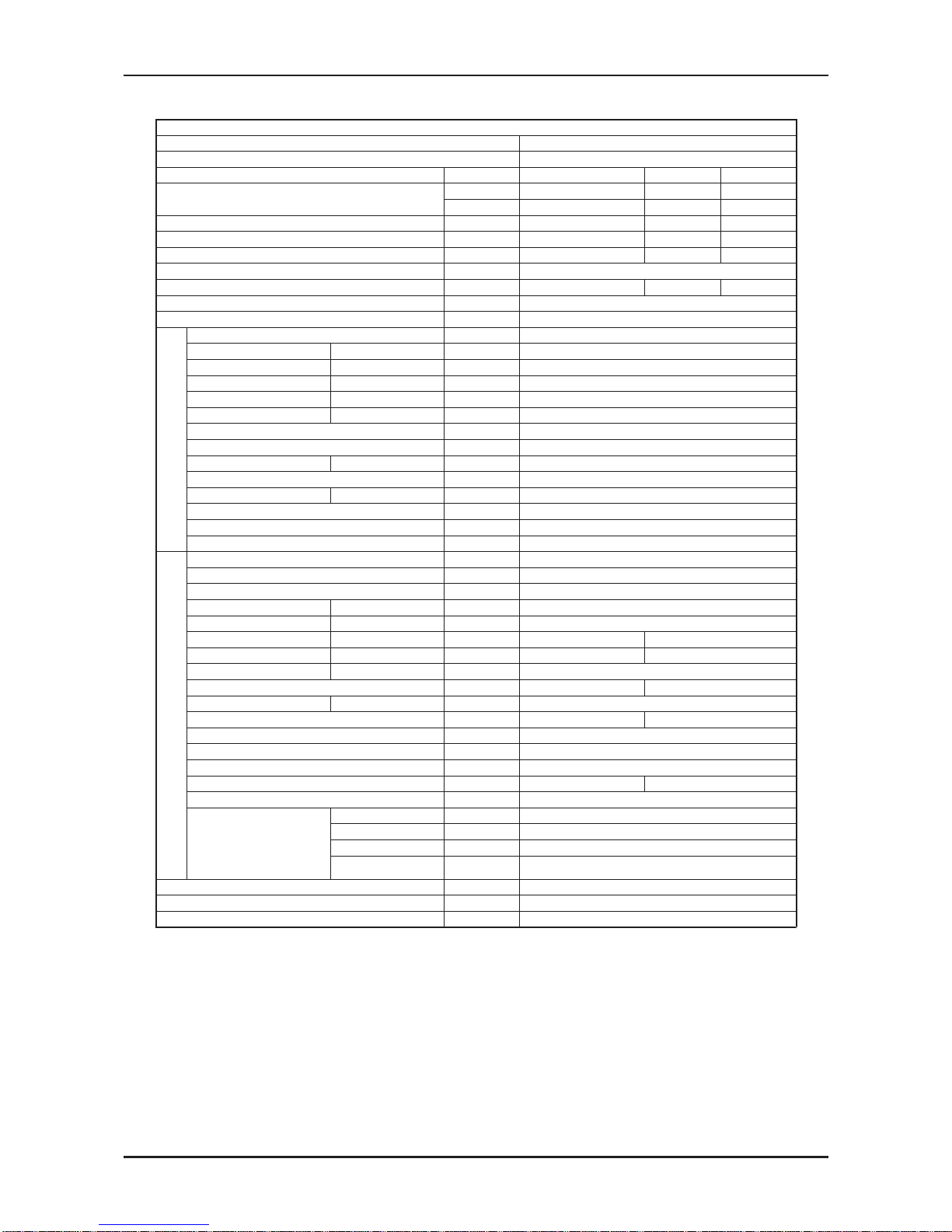
2. PRODUCT DATA SHEET
2.1 R410A
Model Indoor Unit FLO 7 N
Model Outdoor Unit GC 7 N (ONG-7)
Installation Method of Pipe Flared
Characteristics Units Cooling Only Cooling Heating
Capacity
(1)
Btu/hr 7610 7610 7760
kW 2.23 2.23 2.28
Power input
(1)
kW 0.68 0.68 0.665
EER (Cooling) or COP(Heating)
(1)
W/W 3.28 3.28 3.42
Energy efficiency class
A
AB
Power supply V/Ph/Hz 220-240V/Single/50Hz
Rated current A 3.0 3.0 2.9
Starting current A 15
Circuit breaker rating A 10
INDOOR
Fan type & quantity Crossflow x 1
Fan speeds H/M/L RPM 860/760/660
Air flow
(2)
H/M/L m3/hr 380/320/280
External static
pressure
Min-Max Pa 0
Sound power level
(3)
H/M/L dB(A) 45/41/39
Sound pressure level
(4)
H/M/L dB(A) 30/27/25
Moisture removal l/hr 0.7
Condenstate drain tube I.D mm 16
Dimensions WxHxD mm 810x190x285
Weight kg 11
Package dimensions WxHxD mm 885x360x285
Packaged weight kg 13.5
Units per pallet units 32
Stacking height units 8 levels
OUTDOOR
Refrigerant control Capillary tube (with 026 restrictor)
Compressor type,model Rotary,LG GK086PAE
Fan type & quantity Propeller(direct) x 1
Fan speeds H/L RPM 680
Air flow H/L m3/hr 1660
Sound power level H/L dB(A) 56 57
Sound pressure level
(4)
H/L dB(A) 46 47
Dimensions WxHxD mm 795x290x610
Weight kg 31 32
Package dimensions WxHxD mm 945x395x655
Packaged weight kg 35 36
Units per pallet Units 9
Stacking height units 3 levels
Refrigerant type R410A
Refrigerant chargless distance kg/m 0.77kg/7.5m 0.89kg/7.5m
Additional charge per 1 meter g/m 15
Connections between
units
Liquid line In.(mm) 1/4”(6.35)
Suction line In.(mm) 3/8”(9.53)
Max.tubing length m. Max.15
Max.height
difference
m. Max.7
Operation control type Remote control
Heating elements (Option) kW 0.3
Others
(1)
Rating conditions in accordance with ISO 5151, ISO 13253 (for ducted units) and EN 14511.
(2)
Airflow in ducted units; at nominal external static pressure.
(3)
Sound power in ducted units is measured at air discharge.
(4)
Sound pressure level measured at 1 meter distance from unit.
2-2
PRODUCT DATA SHEET
Revision 0
Model Indoor Unit FLO 9 N
Model Outdoor Unit GC 9 N(ONG-9)
Installation Method of Pipe Flared
Characteristics Units Cooling Only Cooling Heating
Capacity
(1)
Btu/hr 9280 9280 10240
kW 2.72 2.72 3.0
Power input
(1)
kW 0.825 0.825 0.850
EER (Cooling) or COP(Heating)
(1)
W/W 3.30 3.30 3.53
Energy efficiency class
A
AB
Power supply V/Ph/Hz 220-240V/Single/50Hz
Rated current A 3.7 3.7 3.8
Starting current A 18.7
Circuit breaker rating A 10
INDOOR
Fan type & quantity Crossflow x 1
Fan speeds H/M/L RPM 960/860/760
Air flow
(2)
H/M/L m3/hr 450/380/330
External static pressure Min-Max Pa 0
Sound power level
(3)
H/M/L dB(A) 49/46/44
Sound pressure level
(4)
H/M/L dB(A) 35/31/28
Moisture removal l/hr 0.9
Condenstate drain tube I.D mm 16
Dimensions WxHxD mm 810x190x285
Weight kg 11
Package dimensions WxHxD mm 885x285x360
Packaged weight kg 13.5
Units per pallet units 32
Stacking height units 8 levels
OUTDOOR
Refrigerant control Capillary tube (with 029 restrictor)
Compressor type,model Rotary,LG GK113PAG
Fan type & quantity Propeller(direct) x 1
Fan speeds H/L RPM 780
Air flow H/L m3/hr 1780
Sound power level H/L dB(A) 58 60
Sound pressure level
(4)
H/L dB(A) 48 49
Dimensions WxHxD mm 795x290x610
Weight kg 34 35
Package dimensions WxHxD mm 945x395x655
Packaged weight kg 38 39
Units per pallet Units 9
Stacking height units 3 levels
Refrigerant type R410A
Refrigerant chargless distance kg/m 0.96kg/7.5m 1kg/7.5m
Additional charge per 1 meter g/m 10
Connections between
units
Liquid line In.(mm) 1/4”(6.35)
Suction line In.(mm) 3/8”(9.53)
Max.tubing length m. Max.15
Max.height
difference
m. Max.7
Operation control type Remote control
Heating elements (Option) kW 0.3
Others
(1)
Rating conditions in accordance with ISO 5151, ISO 13253 (for ducted units) and EN 14511.
(2)
Airflow in ducted units; at nominal external static pressure.
(3)
Sound power in ducted units is measured at air discharge.
(4)
Sound pressure level measured at 1 meter distance from unit.

2-3
PRODUCT DATA SHEET
Revision 0
Model Indoor Unit FLO 12 N
Model Outdoor Unit GC 12 N (ONG-12)
Installation Method of Pipe Flared
Characteristics Units Cooling Only Cooling Heating
Capacity
(1)
Btu/hr 12390 12390 13650
kW 3.63 3.63 4.0
Power input
(1)
kW 1.115 1.115 1.14
EER (Cooling) or COP(Heating)
(1)
W/W 3.26 3.26 3.51
Energy efficiency class
A
AB
Power supply V/Ph/Hz 220-240V/Single/50Hz
Rated current A 5.0 5.0 5.1
Starting current A 25
Circuit breaker rating A 15
INDOOR
Fan type & quantity Crossflow x 1
Fan speeds H/M/L RPM 1230/1080/930
Air flow
(2)
H/M/L m3/hr 635/550/450
External static pressure Min-Max Pa 0
Sound power level
(3)
H/M/L dB(A) 55/53/49
Sound pressure level
(4)
H/M/L dB(A) 43/39/35
Moisture removal l/hr 1.3
Condenstate drain tube I.D mm 16
Dimensions WxHxD mm 810x190x285
Weight kg 11.5
Package dimensions WxHxD mm 885x360x285
Packaged weight kg 13.5
Units per pallet units 32
Stacking height units 8 levels
OUTDOOR
Refrigerant control Capillary tube
Compressor type,model Rotary,PA145X2C-4FT
Fan type & quantity Propeller(direct) x 1
Fan speeds H/L RPM 810
Air flow H/L m3/hr 1850
Sound power level H/L dB(A) 62 64
Sound pressure level(4) H/L dB(A) 52 53
Dimensions WxHxD mm 795x290x610
Weight kg 35 36
Package dimensions WxHxD mm 945x395x655
Packaged weight kg 39 40
Units per pallet Units 9
Stacking height units 3 levels
Refrigerant type R410A
Refrigerant chargless distance kg/m 1.15kg/7.5m 1.15kg/7.5m
Additional charge per 1 meter g/m 12
Connections between
units
Liquid line In.(mm) 1/4”(6.35)
Suction line In.(mm) 3/8”(9.53)
Max.tubing length m. Max.15
Max.height
difference
m. Max.7
Operation control type Remote control
Heating elements (Option) kW 0.3
Others
(1)
Rating conditions in accordance with ISO 5151, ISO 13253 (for ducted units) and EN 14511.
(2)
Airflow in ducted units; at nominal external static pressure.
(3)
Sound power in ducted units is measured at air discharge.
(4)
Sound pressure level measured at 1 meter distance from unit.

2-4
PRODUCT DATA SHEET
Revision 0
Model Indoor Unit FLO 14 N
Model Outdoor Unit GC14 N (ONG-14)
Installation Method of Pipe Flared
Characteristics Units Cooling Only Cooling Heating
Capacity
(1)
Btu/hr 13650 13650 15290
kW 4.0 4.0 4.48
Power input
(1)
kW 1.33 1.33 1.395
EER (Cooling) or COP(Heating)
(1)
W/W 3.01 3.01 3.21
Energy efficiency class
B
BC
Power supply V/Ph/Hz 220-240V/Single/50Hz
Rated current A 6.1 6.1 6.5
Starting current A 30
Circuit breaker rating A 15
INDOOR
Fan type & quantity Crossflow x 1
Fan speeds H/M/L RPM 1280/1080/930
Air flow
(2)
H/M/L m3/hr 660/550/475
External static pressure Min-Max Pa 0
Sound power level
(3)
H/M/L dB(A) 56/51/46
Sound pressure level
(4)
H/M/L dB(A) 46/41/36
Moisture removal l/hr 1.5
Condenstate drain tube I.D mm 16
Dimensions WxHxD mm 810x190x285
Weight kg 11.5
Package dimensions WxHxD mm 885x360x285
Packaged weight kg 14
Units per pallet units 32
Stacking height units 8 levels
OUTDOOR
Refrigerant control Capillary tube
Compressor type,model Rotary,RN165VHSMT
Fan type & quantity Propeller(direct) x 1
Fan speeds H/L RPM 920
Air flow H/L m3/hr 2160
Sound power level H/L dB(A) 63 64
Sound pressure level
(3)
H/L dB(A) 53 54
Dimensions WxHxD mm 795x290x610
Weight kg 41.5 42.2
Package dimensions WxHxD mm 945x395x655
Packaged weight kg 45.5 46.5
Units per pallet Units 9
Stacking height units 3 levels
Refrigerant type R410A
Refrigerant chargless distance kg/m 1.34kg/7.5m
Additional charge per 1 meter g/m 20
Connections between
units
Liquid line In.(mm) 1/4”(6.35)
Suction line In.(mm) 1/2”(12.7)
Max.tubing length m. Max.15
Max.height
difference
m. Max.7
Operation control type Remote control
Heating elements (Option) kW 0.3
Others
(1)
Rating conditions in accordance with ISO 5151, ISO 13253 (for ducted units) and EN 14511.
(2)
Airflow in ducted units; at nominal external static pressure.
(3)
Sound power in ducted units is measured at air discharge.
(4)
Sound pressure level measured at 1 meter distance from unit.

2-5
PRODUCT DATA SHEET
Revision 0
Model Indoor Unit FLO 18 N
Model Outdoor Unit GC 18 N
Installation Method of Pipe Flared
Characteristics Units Cooling Only Cooling Heating
Capacity
(1)
Btu/hr 18250 18250 18420
kW 5.35 5.35 5.40
Power input
(1)
kW 1.66 1.66 1.56
EER (Cooling) or COP(Heating)
(1)
W/W 3.22 3.22 3.46
Energy efficiency class
A
AB
Power supply V/Hz/Ph 220-240V/50Hz/Single
Rated current A 7.5 7.5 7.1
Starting current A 43
Circuit breaker rating A 15
INDOOR
Fan type & quantity Cross flow*1
Fan speeds H/M/L RPM 1200/1100/1000
Air flow
(2)
H/M/L m3/hr 930/840/750
External static pressure Min-Max Pa N/A
Sound power level
(3)
H/M/L dB(A) 56-53-50
Sound pressure level
(4)
H/M/L dB(A) 43-40-37
Moisture removal l/hr 1.8
Condenstate drain tube I.D mm 16
Dimensions WxHxD mm 1060x295x210
Weight kg 14
Package dimensions WxHxD mm 1115x350x260
Packaged weight kg 17
Units per pallet units 16
Stacking height units 8
OUTDOOR
Refrigerant control Capillary tube
Compressor type,model Rotary,TOSHIBA PA200X2CS-4KU1
Fan type & quantity Propeller(direct) x 1
Fan speeds H/L RPM 815
Air flow H/L m3/hr 2480
Sound power level H/L dB(A) 68
Sound pressure level
(4)
H/L dB(A) 57
Dimensions WxHxD mm 846*302*690
Weight kg 56
Package dimensions WxHxD mm 990*430*770
Packaged weight kg 61
Units per pallet Units 9
Stacking height units 3
Refrigerant type R410A
Refrigerant chargless distance kg/m 1.54kg/7.5m
Additional charge g/m
4m≤Length≤10m 1540g 10m Length≤18m 1690g
18m Length≤25m 1900g
Connections between
units
Liquid line In.(mm) 1/4”(6.35)
Suction line In.(mm) 1/2”(12.7)
Max.tubing length m. 25
Max.height
difference
m. 15
Operation control type Remote control
Heating elements kW
Others All season kit Factory option
(1)
Rating conditions in accordance with ISO 5151, ISO 13253 (for ducted units) and EN 14511.
(2)
Airflow in ducted units; at nominal external static pressure.
(3)
Sound power in ducted units is measured at air discharge.
(4)
Sound pressure level measured at 1 meter distance from unit.

2-6
PRODUCT DATA SHEET
Revision 0
Model Indoor Unit FLO 24 N
Model Outdoor Unit GC 24 N (OU7-24)
Installation method WALL MOUNTED
Characteristics Units Cooling only Cooling Heating
Capacity
(1)
Btu/hr 23100 23100 24150
kW 6.77 6.77 7.08
Power input
(1)
kW 2.24 2.24 2.4
COP
(1)
W/W 3.02 3.02 3.01
Energy efficiency class B B D
Power supply V/ Ph /Hz 230/50/1
Rated current A 9.3 10.2
Starting current A 63
Circuit breaker rating A 20
INDOOR
Fan type & quantity CROSS FLOW *1
Fan speeds H/ M/ L RPM 1300 1200 1100
Air flow
(2)
H/ M/ L m³/hr 910 820 740
External static pressure Min-Max Pa N/A
Sound power level
(3)
H/ M/ L dB(A) 60 57 55
Sound pressure level
(4)
H/ M/ L dB(A) 47 44 42
Moisture removal L/hr 2.3
Condensate drain tube I.D mm 16
Dimensions W/ H / D mm 1060 295 210
Weight kg 15
Package dimensions W/ H / D mm 1125 360 280
Packaged weight kg 18
Units per pallet Units 16
Stacking height Units 8
OUTDOOR
Refrigerant control CAPILLARY TUBE
Compressor type, model ROTARY
Fan type & quantity AXIAL*1
Fan speeds H / L RPM 850 720
Air flow H / L m³/hr 1520 1100
Sound power level H / L
dB(A)
67 62
Sound pressure level
(4)
H / L
dB(A)
58 54
Dimensions W/ H / D mm 900 680 340
Weight kg 74
Package dimensions W/ H / D mm
985 730 406
Packaged weight kg
77
Units per pallet Units 6
Stacking height Units 2
Refrigerant type R410A
Refrigerant chargless distance kg/m 2.035/12.5
Additional charge g/m
12.5m<Add 350g<15m
15m<Add 1040g<20m
Connections
between units
Liquid line In. 3/8
Suction line In. 5/8
Max. tubing length m. 20
Max. height difference m. 15
Operation control type LCD REMOTE CONTROL
Heating elements kW
Others All season kit Factory option
1) Rating conditions in accordance with ISO 5151 and ISO 13253 (for ducted units) and EN14511.
(2) Airflow in ducted units; at nominal external static pressure.
(3) Sound power in ducted units is measured at air discharge.
(4) Sound pressure level measured at 1 meter distance from unit.

2-7
PRODUCT DATA SHEET
Revision 0
Model Indoor Unit FLO 24 N
Model Outdoor Unit GC 24 N T (OU7-24 T)
Installation method WALL MOUNTED
Characteristics Units Cooling only Cooling Heating
Capacity
(1)
Btu/hr 23220 23220 25130
kW 6.81 6.81 7.37
Power input
(1)
kW 2.26 2.26 2.4
COP
(1)
W/W 3.01 3.01 3.07
Energy efficiency class B B D
Power supply V/ Ph /Hz 400/50/3N
Rated current A 4.1*3 4.4*3
Starting current A 55
Circuit breaker rating A 10*3
INDOOR
Fan type & quantity CROSS FLOW *1
Fan speeds H/ M/ L RPM 1300 1200 1100
Air flow
(2)
H/ M/ L m³/hr 990 930 840
External static pressure Min-Max Pa N/A
Sound power level
(3)
H/ M/ L dB(A) 58 55 53
Sound pressure level
(4
) H/ M/ L dB(A) 45 42 40
Moisture removal L/hr 2.3
Condensate drain tube I.D mm 16
Dimensions W/ H / D mm 1060 295 210
Weight kg 15
Package dimensions W/ H / D mm 1115 350 260
Packaged weight kg 18
Units per pallet Units 16
Stacking height Units 8
OUTDOOR
Refrigerant control CAPILLARY TUBE
Compressor type, model ROTARY
Fan type & quantity AXIAL*1
Fan speeds H / L RPM 850 720
Air flow H / L m³/hr 1520 1100
Sound power level H / L
dB(A)
67 62
Sound pressure level
(4)
H / L
dB(A)
58 54
Dimensions W/ H / D mm 900 680 340
Weight kg 74
Package dimensions W/ H / D mm
985 730 406
Packaged weight kg
74
Units per pallet Units 6
Stacking height Units 2
Refrigerant type R410A
Refrigerant chargless distance kg/m 2.035/12.5
Additional charge g/m
12.5m<Add 350g<15m
12.5m<Add 1040g<20m
Connections
between units
Liquid line In. 3/8
Suction line In. 5/8
Max. tubing length m. 20
Max. height difference m. 15
Operation control type LCD REMOTE CONTROL
Heating elements kW
Others All season kit Factory option
1) Rating conditions in accordance with ISO 5151 and ISO 13253 (for ducted units) and EN14511.
(2) Airflow in ducted units; at nominal external static pressure.
(3) Sound power in ducted units is measured at air discharge.
(4) Sound pressure level measured at 1 meter distance from unit.

2-10
PRODUCT DATA SHEET
Revision 0
Model Indoor Unit FLO 30N
Model Outdoor Unit GC30N(OU830)
Installation Method of Pipe Flared
Characteristics Units Cooling Only Cooling Heating
Capacity
(1)
Btu/hr 29550 29550 31800
kW 8.66 8.66 9.33
Power input
(1)
kW 3.08 3.08 3.27
EER (Cooling) or COP(Heating)
(1)
W/W 2.81 2.81 2.85
Energy efficiency class C C C
Power supply V/Ph/Hz 220-240V/Single/50Hz
Rated current A 13.4 13.4 14.2
Starting current A 75
Circuit breaker rating A 25
INDOOR
Fan type & quantity Cross flow x 1
Fan speeds H/M/L RPM 1300/1200/1000
Air flow
(2)
H/M/L m3/hr 1250/1040/830
External static pressure Min-Max Pa N/A
Sound power level
(3)
H/M/L dB(A) 64/59/53
Sound pressure level
(4)
H/M/L dB(A) 54/52/41
Moisture removal l/hr 3.6
Condensate drain tube I.D mm 16
Dimensions WxHxD mm 1200X340X236
Weight kg 18.5
Package dimensions WxHxD mm 1305X430X325
Packaged weight kg 25.5
Units per pallet units 12
Stacking height units 6 levels
OUTDOOR
Refrigerant control Capillary
Compressor type, model SCROLL AQ036PAA
Fan type & quantity Propeller(direct) x 1
Fan speeds H/L RPM 850
Air flow H/L m3/hr 3110
Sound power level H/L dB(A) 69
Sound pressure level
(4)
H/L dB(A) 62
Dimensions WxHxD mm 900X860X340
Weight kg 78
Package dimensions WxHxD mm 903X907X435
Packaged weight kg 82
Units per pallet Units 6
Stacking height units 3 levels
Refrigerant type R410A
Refrigerant charge less distance kg/m 2.1kg / 7.5m
Additional charge gr/m 30
Connections between
units
Liquid line In.(mm) 3/8”(9.53)
Suction line In.(mm) 3/4”(19.05)
Max.tubing length m. 30
Max.height
difference
m. 10
Operation control type Remote control
Heating elements kW
(1)
Rating conditions in accordance with ISO 5151, ISO 13253 (for ducted units) and EN 14511.
(2)
Airflow in ducted units; at nominal external static pressure.
(3)
Sound power in ducted units is measured at air discharge.
(4)
Sound pressure level measured at 1 meter distance from unit.

2-11
PRODUCT DATA SHEET
Revision 0
Model Indoor Unit FLO 30N
Model Outdoor Unit GC30NT(OU830T)
Installation Method of Pipe Flared
Characteristics Units Cooling Only Cooling Heating
Capacity
(1)
Btu/hr 29580 29580 31630
kW 8.67 8.67 9.27
Power input
(1)
kW 3.09 3.09 3.25
EER (Cooling) or COP(Heating)
(1)
W/W 2.81 2.81 2.85
Energy efficiency class C C C
Power supply V/Ph/Hz 400V/3PH/50Hz
Rated current A 10.2 10.2 10.6
Starting current A 35
Circuit breaker rating A 16
INDOOR
Fan type & quantity Cross flow x 1
Fan speeds H/M/L RPM 1300/1200/1000
Air flow
(2)
H/M/L m3/hr 1250/1040/830
External static pressure Min-Max Pa N/A
Sound power level
(3)
H/M/L dB(A) 64/59/53
Sound pressure level
(4)
H/M/L dB(A) 54/52/41
Moisture removal l/hr 3.6
Condensate drain tube I.D mm 16
Dimensions WxHxD mm 1200X340X236
Weight kg 18.5
Package dimensions WxHxD mm 1305X430X325
Packaged weight kg 25.5
Units per pallet units 12
Stacking height units 6 levels
OUTDOOR
Refrigerant control Capillary
Compressor type, model SCROLL AQ036YAA
Fan type & quantity Propeller(direct) x 1
Fan speeds H/L RPM 850
Air flow H/L m3/hr 3110
Sound power level H/L dB(A) 69
Sound pressure level
(4)
H/L dB(A) 62
Dimensions WxHxD mm 900X860X340
Weight kg 78
Package dimensions WxHxD mm 903X907X435
Packaged weight kg 82
Units per pallet Units 6
Stacking height units 3 levels
Refrigerant type R410A
Refrigerant charge less distance kg/m 2.13kg / 7.5m
Additional charge gr/m 30
Connections between
units
Liquid line In.(mm) 3/8”(9.53)
Suction line In.(mm) 3/4”(15.88)
Max.tubing length m. 30
Max.height
difference
m. 10
Operation control type Remote control
(1)
Rating conditions in accordance with ISO 5151, ISO 13253 (for ducted units) and EN 14511.
(2)
Airflow in ducted units; at nominal external static pressure.
(3)
Sound power in ducted units is measured at air discharge.
(4)
Sound pressure level measured at 1 meter distance from unit.

3-1
RATING CONDITIONS
Revision 0
3. RATING CONDITIONS
Standard conditions in accordance with ISO 5151, ISO 13253 (for ducted units)
and EN 14511.
Cooling:
Indoor: 27
o
C DB 19oC WB
Outdoor: 35
o
C DB
Heating:
Indoor: 20
o
C DB
Outdoor: 7
o
C DB 6oC WB
3.1 Operating Limits
3.1.1 R410A
Indoor Outdoor
Cooling
Upper limit 32
o
C DB 23oC WB 46oC DB
Lower limit 21
o
C DB 15oC WB 10oC DB
Heating
Upper limit 27
o
C DB 24oC DB 18oC WB
Lower limit 10
o
C DB -9oC DB -10oC WB
Volt age
1PH 198 – 264 V
3PH 360 – 440 V

4-1
OUTLINE DIMENSIONS
Revision 0
4. OUTLINE DIMENSIONS
4.1 FLO N 7 , 9 , 12, 14
4.2
FLO N 18/24

4-2
OUTLINE DIMENSIONS
Revision 0
4.3 FLO N 30
4.4
ONG 7, 9, 12, 14 RC
150mm

4-3
OUTLINE DIMENSIONS
Revision 0
4.5 GCN 7, 9, 12, 14 RC
4.6 GC 18, 24 RC
AI R OUTL E T
AI R I NTAKE

4-4
OUTLINE DIMENSIONS
Revision 0
4.7 OU7-24 RC
4.8 GC 30 N RC

4-5
OUTLINE DIMENSIONS
Revision 0
4.9 OU8-30 RC

5-1
PERFORMANCE DATA & PRESSURE CURVES
Revision 0
5. PERFORMANCE DATA & PRESSURE CURVES
5.1 FLO 7 N R410A
5.1.1 Cooling Mode at 7.5m Tubing Connection.
230V : Indoor Fan at High Speed.
ENTERING AIR
DB OU COIL (°C)
DATA
ENTERING AIR WB/DB ID COIL ( °C)
15/21 17/24 19/27 21/29 23/32
15
(1)
TC
2.35 2.43 2.49 2.55 2.59
SC
1.66 1.74 1.80 1.85 1.88
PI
0.48 0.48 0.48 0.49 0.49
20
(1)
TC
2.27 2.40 2.47 2.53 2.57
SC
1.63 1.72 1.79 1.84 1.88
PI
0.52 0.53 0.53 0.53 0.53
25
TC
2.15 2.32 2.44 2.52 2.58
SC
1.59 1.69 1.78 1.83 1.86
PI
0.57 0.57 0.57 0.58 0.58
30
TC
2.01 2.19 2.37 2.45 2.52
SC
1.54 1.64 1.74 1.79 1.83
PI
0.61 0.62
0.62
0.63 0.64
35
TC
1.86 2.02
2.23
2.34 2.45
SC
1.46 1.57 1.70 1.75 1.78
PI
0.66 0.67
0.68
0.69 0.69
40
TC
1.69 1.84
2.01
2.20 2.31
SC
1.38 1.49 1.61 1.66 1.69
PI
0.71 0.72 0.73 0.74 0.75
46
TC
1.47 1.61 1.77 1.95 2.10
SC
1.27 1.36 1.47 1.52 1.55
PI
0.78 0.79 0.81 0.82 0.83
LEGEND
TC – Total Cooling Capacity, kW
SC – Sensible Capacity, kW
PI – Power Input, kW
WB – Wet Bulb Temp., (
o
C)
DB – Dry Bulb Temp., (oC)
ID – Indoor
OU – Outdoor
(1) Marked area is below standard operating limits. For operating in low ambient
conditions, refer to Optional Accessories (Chapter 14).

5-2
PERFORMANCE DATA & PRESSURE CURVES
Revision 0
5.1.2 Heating Mode at 7.5m Tubing Connection.
230V : Indoor Fan at High Speed.
ENTERING AIR DB ID COIL ( °C)
15 20 25
ENTERING AIR
WB OU COIL ( °C)
TH PI TH PI TH PI
-10 1.20 0.54 1.15 0.57 1.11 0.60
-7 1.29 0.55 1.24 0.58 1.20 0.61
-2 1.37 0.56 1.32 0.59 1.28 0.62
2 1.66 0.58
1.60 0.62
1.53 0.66
6 2.35 0.63 2.28 0.67 2.20 0.71
10 2.55 0.66
2.49 0.71
2.42 0.76
15 2.76 0.69 2.69 0.74 2.62 0.79
20 2.91 0.71 2.84 0.77 2.76 0.83
* the above chart includes the weighted deicing infleuence.
LEGEND
TH – Total Heating Capacity, kW
PI – Power Input, kW
WB – Wet Bulb Temp., (
o
C)
DB – Dry Bulb Temp., (
o
C)
ID – Indoor
OU – Outdoor
5.2 Capacity Correction Factor Due to Tubing Length
5.2.1 Cooling
TOTAL TUBING LENGTH (One Way)
3m
7.5m
10m 15m 20m 25m 30m 40m 50m
1.02
1
0.961 0.949 --- --- --- --- ---
* Minimum recommended tubing length between indoor and outdoor units is 3m.
5.2.2 Heating
TOTAL TUBING LENGTH (One Way)
3m
7.5m
10m 15m 20m 25m 30m 40m 50m
1.05
1
0.975 0.965 --- --- --- --- ---
* Minimum recommended tubing length between indoor and outdoor units is 3m.

5-3
PERFORMANCE DATA & PRESSURE CURVES
Revision 0
5.3 Pressure Curves.
5.3.1 Cooling.
Discharge Pressure VS.Outdoor Temp
10
15
20
25
30
35
40
15 20 25 30 35 40 46
Outdoor Temp.(DB oC )
Discharge Pressure (Bar[g])
15/21(W B/DB ºC)
17/24(W B/DB ºC)
19/27(W B/DB ºC)
21/29(W B/DB ºC)
23/32(W B/DB ºC)
Suction Pressure VS.Outdoor Temp
7.0
7.5
8.0
8.5
9.0
9.5
10.0
10.5
11.0
11.5
12.0
15 20 25 30 35 40 46
Outdoor Temp.(DB oC )
Suction Pressure (Bar[g])
15/21(WB/DB ºC)
17/24(WB/DB ºC)
19/27(WB/DB ºC)
21/29(WB/DB ºC)
23/32(WB/DB ºC)

5-4
PERFORMANCE DATA & PRESSURE CURVES
Revision 0
5.3.2 Heating.
Discharge Pressure VS.Outdoor Temp
14
16
18
20
22
24
26
28
30
32
34
-10 -5 0 5 10 15 20
Outdoor Temp.( WB oC )
Discharge Pressure(Bar[g])
25 DB (ºC)
20 DB (ºC)
15 DB (ºC)
Suction Pressure VS.Outdoor Temp
3.0
4.0
5.0
6.0
7.0
8.0
9.0
10.0
11.0
12.0
-10 -5 0 5 10 15 20
Outdoor Temp.( WB oC )
Suction Pressure(Bar[g])
15 DB (ºC)
20 DB (ºC)
25 DB (ºC)

5-5
PERFORMANCE DATA & PRESSURE CURVES
Revision 0
5.4 FLO9N R410A
5.4.1 Cooling Mode at 7.5m Tubing Connection.
230V : Indoor Fan at High Speed.
ENTERING AIR
DB OU COIL (°C)
DATA
ENTERING AIR WB/DB ID COIL ( °C)
15/21 17/24 19/27 21/29 23/32
15
(1)
TC
2.87 2.97 3.04 3.11 3.16
SC
1.96 2.04 2.12 2.18 2.22
PI
0.59 0.59 0.59 0.59 0.60
20
(1)
TC
2.77 2.92 3.02 3.09 3.14
SC
1.92 2.02 2.11 2.17 2.21
PI
0.64 0.64 0.64 0.65 0.65
25
TC
2.62 2.83 2.98 3.07 3.14
SC
1.87 1.98 2.09 2.15 2.19
PI
0.69 0.70 0.70 0.70 0.71
30
TC
2.45 2.67 2.89 2.99 3.08
SC
1.81 1.93 2.05 2.11 2.15
PI
0.74 0.76
0.76
0.77 0.78
35
TC
2.27 2.47
2.72
2.86 2.99
SC
1.72 1.85 2.00 2.06 2.10
PI
0.80 0.82
0.83
0.84 0.84
40
TC
2.07 2.25
2.45
2.68 2.82
SC
1.62 1.75 1.89 1.95 1.99
PI
0.87 0.88 0.89 0.91 0.91
46
TC
1.79 1.96 2.16 2.38 2.57
SC
1.50 1.60 1.73 1.79 1.83
PI
0.95 0.96 0.98 1.00 1.01
LEGEND
TC – Total Cooling Capacity, kW
SC – Sensible Capacity, kW
PI – Power Input, kW
WB – Wet Bulb Temp., (
o
C)
DB – Dry Bulb Temp., (oC)
ID – Indoor
OU – Outdoor
(1) Marked area is below standard operating limits. For operating in low ambient
conditions, refer to Optional Accessories (Chapter 14).
5-6
PERFORMANCE DATA & PRESSURE CURVES
Revision 0
5.4.2 Heating Mode at 7.5m Tubing Connection.
230V : Indoor Fan at High Speed.
ENTERING AIR DB ID COIL ( °C)
15 20 25
ENTERING AIR
WB OU COIL (°C)
TH PI TH PI TH PI
-10 1.58 0.68 1.52 0.72 1.46 0.76
-7 1.70 0.70 1.64 0.74 1.58 0.78
-2 1.80 0.71 1.74 0.75 1.68 0.79
2 2.19 0.74
2.10 0.79
2.01 0.83
6 3.09 0.79 3.00 0.85 2.90 0.90
10 3.36 0.84
3.27 0.90
3.18 0.96
15 3.63 0.88 3.54 0.94 3.45 1.00
20 3.83 0.90 3.74 0.98 3.63 1.05
* the above chart includes the weighted deicing infleuence.
LEGEND
TH – Total Heating Capacity, kW
PI – Power Input, kW
WB – Wet Bulb Temp., (
o
C)
DB – Dry Bulb Temp., (
o
C)
ID – Indoor
OU – Outdoor
5.5 Capacity Correction Factor Due to Tubing Length
5.5.1 Cooling
TOTAL TUBING LENGTH (One Way)
3m
7.5m
10m 15m 20m 25m 30m 40m 50m
1.02
1
0.961 0.950 --- --- --- --- ---
* Minimum recommended tubing length between indoor and outdoor units is 3m.
5.5.2 Heating
TOTAL TUBING LENGTH (One Way)
3m
7.5m
10m 15m 20m 25m 30m 40m 50m
1.05
1
0.975 0.961 --- --- --- --- ---
* Minimum recommended tubing length between indoor and outdoor units is 3m.

5-7
PERFORMANCE DATA & PRESSURE CURVES
Revision 0
5.6 Pressure Curves.
5.6.1 Cooling.
Discharge Pressure VS.Outdoor Temp
10
15
20
25
30
35
40
15 20 25 30 35 40 46
Outdoor Temp.(DB oC )
Discharge Pressure (Bar[g])
15/21(WB/DB ºC)
17/24(WB/DB ºC)
19/27(WB/DB ºC)
21/29(WB/DB ºC)
23/32(WB/DB ºC)
Suction Pressure VS.Outdoor Temp
6.0
6.5
7.0
7.5
8.0
8.5
9.0
9.5
10.0
10.5
11.0
11.5
12.0
15 20 25 30 35 40 46
Outdoor Temp.(DB oC )
Suction Pressure (Bar[g])
15/21(WB/DB ºC)
17/24(WB/DB ºC)
19/27(WB/DB ºC)
21/29(WB/DB ºC)
23/32(WB/DB ºC)

5-8
PERFORMANCE DATA & PRESSURE CURVES
Revision 0
5.6.2 Heating.
Discharge Pressure VS.Outdoor Temp
14
16
18
20
22
24
26
28
30
32
34
36
-10 -5 0 5 10 15 20
Outdoor Temp.( WB oC )
Discharge Pressure(Bar[g])
25 DB (ºC)
20 DB (ºC)
15 DB (ºC)
Suction Pressure VS.Outdoor Temp
3.0
4.0
5.0
6.0
7.0
8.0
9.0
10.0
11.0
12.0
-10 -5 0 5 10 15 20
Outdoor Temp.( WB oC )
Suction Pressure(Bar[g])
15 DB (ºC)
20 DB (ºC)
25 DB (ºC)

5-9
PERFORMANCE DATA & PRESSURE CURVES
Revision 0
5.7 FLO12N R410A
5.7.1 Cooling Mode at 7.5m Tubing Connection.
230V : Indoor Fan at High Speed.
ENTERING AIR
DB OU COIL (°C)
DATA
ENTERING AIR WB/DB ID COIL ( °C)
15/21 17/24 19/27 21/29 23/32
15
(1)
TC
3.83 3.96 4.06 4.15 4.22
SC
2.67 2.79 2.90 2.97 3.02
PI
0.79 0.80 0.80 0.80 0.80
20
(1)
TC
3.70 3.90 4.02 4.12 4.19
SC
2.62 2.76 2.88 2.96 3.02
PI
0.86 0.87 0.87 0.87 0.87
25
TC
3.50 3.78 3.98 4.10 4.20
SC
2.55 2.71 2.86 2.94 2.99
PI
0.93 0.94 0.94 0.95 0.96
30
TC
3.28 3.57 3.85 3.99 4.11
SC
2.47 2.63 2.79 2.88 2.93
PI
1.01 1.02
1.03
1.04 1.05
35
TC
3.03 3.29
3.63
3.81 3.99
SC
2.35 2.52 2.73 2.81 2.86
PI
1.08 1.10
1.12
1.13 1.13
40
TC
2.76 3.00
3.28
3.58 3.77
SC
2.22 2.39 2.58 2.66 2.72
PI
1.17 1.19 1.21 1.22 1.23
46
TC
2.39 2.62 2.88 3.18 3.42
SC
2.04 2.19 2.35 2.44 2.49
PI
1.28 1.30 1.33 1.35 1.36
LEGEND
TC – Total Cooling Capacity, kW
SC – Sensible Capacity, kW
PI – Power Input, kW
WB – Wet Bulb Temp., (
o
C)
DB – Dry Bulb Temp., (
o
C)
ID – Indoor
OU – Outdoor
(1) Marked area is below standard operating limits. For operating in low ambient
conditions, refer to Optional Accessories (Chapter 14).

5-10
PERFORMANCE DATA & PRESSURE CURVES
Revision 0
5.7.2 Heating Mode at 7.5m Tubing Connection.
230V : Indoor Fan at High Speed.
ENTERING AIR DB ID COIL ( °C)
15 20 25
ENTERING AIR WB
OU COIL (°C)
TH PI TH PI TH PI
-10 2.10 0.91 2.02 0.97 1.94 1.02
-7 2.26 0.93 2.18 0.99 2.10 1.04
-2 2.40 0.95 2.32 1.00 2.24 1.06
2 2.92 0.99
2.80 1.05
2.68 1.12
6 4.12 1.07 4.00 1.14 3.86 1.21
10 4.48 1.13
5.00 1.20
4.24 1.29
15 4.84 1.17 4.72 1.27 4.60 1.35
20 5.10 1.21 4.98 1.31 4.84 1.41
* the above chart includes the weighted deicing infleuence.
LEGEND
TH – Total Heating Capacity, kW
PI – Power Input, kW
WB – Wet Bulb Temp., (
o
C)
DB – Dry Bulb Temp., (
o
C)
ID – Indoor
OU – Outdoor
5.8 Capacity Correction Factor Due to Tubing Length
5.8.1 Cooling
TOTAL TUBING LENGTH (One Way)
3m
7.5m
10m 15m 20m 25m 30m 40m 50m
1.02
1
0.961 0.948 --- --- --- --- ---
* Minimum recommended tubing length between indoor and outdoor units is 3m.
5.8.2 Heating
TOTAL TUBING LENGTH (One Way)
3m
7.5m
10m 15m 20m 25m 30m 40m 50m
1.05
1
0.975 0.963 --- --- --- --- ---
* Minimum recommended tubing length between indoor and outdoor units is 3m.

5-11
PERFORMANCE DATA & PRESSURE CURVES
Revision 0
5.9 Pressure Curves.
5.9.1 Cooling.
Discharge Pressure VS.Outdoor Temp
10
15
20
25
30
35
40
15 20 25 30 35 40 46
Outdoor Temp.(DB oC )
Discharge Pressure (Bar[g])
15/21(WB/DB ºC)
17/24(WB/DB ºC)
19/27(WB/DB ºC)
21/29(WB/DB ºC)
23/32(WB/DB ºC)
Suction Pressure VS.Outdoor Temp
6.0
6.5
7.0
7.5
8.0
8.5
9.0
9.5
10.0
10.5
11.0
11.5
12.0
15 20 25 30 35 40 46
Outdoor Temp.(DB oC )
Suction Pressure (Bar[g])
15/21(WB/DB ºC)
17/24(WB/DB ºC)
19/27(WB/DB ºC)
21/29(WB/DB ºC)
23/32(WB/DB ºC)

5-12
PERFORMANCE DATA & PRESSURE CURVES
Revision
5.9.2 Heating.
Discharge Pressure VS.Outdoor Temp
14
16
18
20
22
24
26
28
30
32
34
36
-10 -5 0 5 10 15 20
Outdoor Temp.( WB oC )
Discharge Pressure(Bar[g])
25 DB (ºC)
20 DB (ºC)
15 DB (ºC)
Suction Pressure VS.Outdoor Temp
3.0
4.0
5.0
6.0
7.0
8.0
9.0
10.0
11.0
12.0
-10 -5 0 5 10 15 20
Outdoor Temp.( WB oC )
Suction Pressure(Bar[g])
15 DB (ºC)
20 DB (ºC)
25 DB (ºC)

5-13
PERFORMANCE DATA & PRESSURE CURVES
Revision 0
5.10 FLO 14 N R410A
5.10.1 Cooling Mode at 7.5m Tubing Connection.
230V : Indoor Fan at High Speed.
ENTERING AIR
DB OU COIL( °C)
DATA
ENTERING AIR WB/DB ID COIL ( °C)
15/21 17/24 19/27 21/29 23/32
15
(1)
TC
4.22 4.37 4.47 4.58 4.65
SC
2.80 2.92 3.03 3.11 3.17
PI
0.94 0.94 0.95 0.95 0.95
20
(1)
TC
4.08 4.30 4.44 4.54 4.62
SC
2.75 2.89 3.02 3.10 3.16
PI
1.02 1.03 1.03 1.04 1.04
25
TC
3.86 4.17 4.38 4.51 4.62
SC
2.67 2.84 2.99 3.08 3.14
PI
1.11 1.11 1.12 1.13 1.14
30
TC
3.61 3.93 4.25 4.40 4.53
SC
2.59 2.75 2.93 3.01 3.07
PI
1.19 1.21
1.22
1.23 1.24
35
TC
3.34 3.63
4.00
4.20 4.40
SC
2.46 2.64 2.86 2.94 3.00
PI
1.29 1.31
1.33
1.34 1.35
40
TC
3.04 3.31
3.61
3.95 4.15
SC
2.32 2.50 2.71 2.79 2.85
PI
1.39 1.41 1.43 1.45 1.47
46
TC
2.64 2.88 3.17 3.50 3.77
SC
2.14 2.29 2.47 2.55 2.61
PI
1.52 1.54 1.57 1.60 1.62
LEGEND
TC – Total Cooling Capacity, kW
SC – Sensible Capacity, kW
PI – Power Input, kW
WB – Wet Bulb Temp., (
o
C)
DB – Dry Bulb Temp., (
o
C)
ID – Indoor
OU – Outdoor
(1) Marked area is below standard operating limits. For operating in low ambient
conditions, refer to Optional Accessories (Chapter 14).

5-14
PERFORMANCE DATA & PRESSURE CURVES
Revision 0
5.10.2 Heating Mode at 7.5m Tubing Connection.
230V : Indoor Fan at High Speed.
ENTERING AIR DB ID COIL ( °C)
15 20 25
ENTERING AIR WB
OU COIL (°C)
TH PI TH PI TH PI
-10 2.35 1.12 2.26 1.19 2.17 1.25
-7 2.53 1.15 2.44 1.21 2.35 1.28
-2 2.69 1.16 2.60 1.23 2.51 1.30
2 3.27 1.22
3.14 1.30
3.00 1.37
6 4.61 1.31 4.48 1.40 4.32 1.49
10 5.02 1.38
4.88 1.48
4.75 1.58
15 5.42 1.44 5.29 1.55 5.15 1.65
20 5.71 1.48 5.58 1.61 5.42 1.74
* the above chart includes the weighted deicing infleuence.
LEGEND
TH – Total Heating Capacity, kW
PI – Power Input, kW
WB – Wet Bulb Temp., (
o
C)
DB – Dry Bulb Temp., (
o
C)
ID – Indoor
OU – Outdoor
5.11 Capacity Correction Factor Due to Tubing Length
5.11.1 Cooling
TOTAL TUBING LENGTH (One Way)
3m
7.5m
10m 15m 20m 25m 30m 40m 50m
1.02
1
0.984 0.946 --- --- --- --- ---
* Minimum recommended tubing length between indoor and outdoor units is 3m.
5.11.2 Heating
TOTAL TUBING LENGTH (One Way)
3m
7.5m
10m 15m 20m 25m 30m 40m 50m
1.03
1
0.995 0.971 --- --- --- --- ---
* Minimum recommended tubing length between indoor and outdoor units is 3m.

5-15
PERFORMANCE DATA & PRESSURE CURVES
Revision 0
5.12 Pressure Curves.
5.12.1 Cooling.
Discharge Pressure VS.Outdoor Temp
10
15
20
25
30
35
40
15 20 25 30 35 40 46
Outdoor Temp.(DB oC )
Discharge Pressure (Bar[g])
15/21(WB/DB ºC)
17/24(WB/DB ºC)
19/27(WB/DB ºC)
21/29(WB/DB ºC)
23/32(WB/DB ºC)
Suction Pressure VS.Outdoor Temp
6.0
6.5
7.0
7.5
8.0
8.5
9.0
9.5
10.0
10.5
11.0
11.5
12.0
15 20 25 30 35 40 46
Outdoor Temp.(DB oC )
Suction Pressure (Bar[g])
15/21(WB/DB ºC)
17/24(WB/DB ºC)
19/27(WB/DB ºC)
21/29(WB/DB ºC)
23/32(WB/DB ºC)

5-16
PERFORMANCE DATA & PRESSURE CURVES
Revision 0
5.12.2 Heating.
Discharge Pressure VS.Outdoor Temp
14
16
18
20
22
24
26
28
30
32
34
36
38
40
-10 -5 0 5 10 15 20
Outdoor Temp.( WB oC )
Discharge Pressure(Bar[g])
25 DB (ºC)
20 DB (ºC)
15 DB (ºC)
Suction Pressure VS.Outdoor Temp
3.0
4.0
5.0
6.0
7.0
8.0
9.0
10.0
11.0
12.0
-10 -5 0 5 10 15 20
Outdoor Temp.( WB oC )
Suction Pressure(Bar[g])
15 DB (ºC)
20 DB (ºC)
25 DB (ºC)

5-17
PERFORMANCE DATA & PRESSURE CURVES
Revision 0
5.13 FLO 18 N R410A
5.13.1 Cooling Mode at 7.5m Tubing Connection.
230V : Indoor Fan at High Speed.
ENTERING AIR
DB OU COIL (°C)
DATA
ENTERING AIR WB/DB ID COIL ( °C)
15/21 17/24 19/27 21/29 23/32
15
(1)
TC
5.64 5.84 5.98 6.12 6.21
SC
3.87 4.03 4.19 4.30 4.38
PI
1.18 1.18 1.18 1.18 1.19
20
(1)
TC
5.46 5.75 5.93 6.07 6.18
SC
3.79 4.00 4.17 4.28 4.36
PI
1.28 1.28 1.29 1.29 1.30
25
TC
5.16 5.57 5.86 6.04 6.18
SC
3.69 3.92 4.13 4.25 4.33
PI
1.38 1.39 1.40 1.41 1.42
30
TC
4.83 5.26 5.68 5.88 6.05
SC
3.58 3.80 4.04 4.16 4.24
PI
1.49 1.51
1.52
1.54 1.55
35
TC
4.47 4.85
5.35
5.62 5.88
SC
3.40 3.65 3.95 4.06 4.14
PI
1.61 1.63
1.66
1.67 1.68
40
TC
4.06 4.42
4.83
5.28 5.55
SC
3.21 3.45 3.74 3.86 3.93
PI
1.73 1.76 1.79 1.81 1.83
46
TC
3.53 3.86 4.24 4.68 5.05
SC
2.95 3.16 3.41 3.53 3.60
PI
1.89 1.92 1.97 1.99 2.02
LEGEND
TC – Total Cooling Capacity, kW
SC – Sensible Capacity, kW
PI – Power Input, kW
WB – Wet Bulb Temp., (
o
C)
DB – Dry Bulb Temp., (
o
C)
ID – Indoor
OU – Outdoor
(1) Marked area is below standard operating limits. For operating in low ambient
conditions, refer to Optional Accessories (Chapter 14).

5-18
PERFORMANCE DATA & PRESSURE CURVES
Revision 0
5.13.2 Heating Mode at 7.5m Tubing Connection.
230V : Indoor Fan at High Speed.
ENTERING AIR DB ID COIL ( °C)
15 20 25
ENTERING AIR
WB OU COIL ( °C)
TH PI TH PI TH PI
-10 2.84 1.25 2.73 1.33 2.62 1.40
-7 3.05 1.28 2.94 1.35 2.84 1.42
-2 3.24 1.29 3.13 1.37 3.02 1.45
2 3.94 1.36
3.78 1.44
3.62 1.53
6 5.56 1.46 5.40 1.56 5.21 1.66
10 6.05 1.54
5.89 1.65
5.72 1.76
15 6.53 1.61 6.37 1.73 6.21 1.84
20 6.89 1.65 6.72 1.79 6.53 1.93
* the above chart includes the weighted deicing infleuence.
LEGEND
TH – Total Heating Capacity, kW
PI – Power Input, kW
WB – Wet Bulb Temp., (
o
C)
DB – Dry Bulb Temp., (
o
C)
ID – Indoor
OU – Outdoor
5.14 Capacity Correction Factor Due to Tubing Length
5.14.1 Cooling
TOTAL TUBING LENGTH
3m
7.5m
10m 15m 20m 25m 30m 40m 50m
1.02
1
0.99 0.975 0.965 0.950 --- --- ---
* Minimum recommended tubing length between indoor and outdoor units is 3m.
5.14.2 Heating
TOTAL TUBING LENGTH
3m
7.5m
10m 15m 20m 25m 30m 40m 50m
1.05
1
1 0.993 0.988 0.978 --- --- ---
* Minimum recommended tubing length between indoor and outdoor units is 3m.

5-19
PERFORMANCE DATA & PRESSURE CURVES
Revision 0
5.15 Pressure Curves.
5.15.1 Cooling.
Suction Pressure VS.Outdoor Temp
6.0
6.5
7.0
7.5
8.0
8.5
9.0
9.5
10.0
10.5
11.0
11.5
12.0
15 20 25 30 35 40 46
Outdoor Temp.(DB oC )
Suction Pressure (Bar[g])
15/21(WB/DB ºC)
17/24(WB/DB ºC)
19/27(WB/DB ºC)
21/29(WB/DB ºC)
23/32(WB/DB ºC)
Discharge Pressure VS.Outdoor Temp
10
12
14
16
18
20
22
24
26
28
30
32
34
36
38
40
15 20 25 30 35 40 46
Outdoor Temp.(DB oC )
Discharge Pressure (Bar[g])
15/21(WB/DB ºC)
17/24(WB/DB ºC)
19/27(WB/DB ºC)
21/29(WB/DB ºC)
23/32(WB/DB ºC)

5-20
PERFORMANCE DATA & PRESSURE CURVES
Revision 0
5.15.2 Heating.
Suction Pressure VS.Outdoor Temp
3.0
4.0
5.0
6.0
7.0
8.0
9.0
10.0
11.0
12.0
-10 -5 0 5 10 15 20
Outdoor Temp.( WB oC )
Suction Pressure(Bar[g])
15 DB (ºC)
20 DB (ºC)
25 DB (ºC)
Discharge Pressure VS.Outdoor Temp
14
16
18
20
22
24
26
28
30
32
34
36
-10 -5 0 5 10 15 20
Outdoor Temp.( WB oC )
Discharge Pressure(Bar[g])
25 DB (ºC)
20 DB (ºC)
15 DB (ºC)

5-21
PERFORMANCE DATA & PRESSURE CURVES
Revision 0
5.16 FLO 24 N 1PH/3PH R410A
5.16.1 Cooling Mode at 7.5m Tubing Connection.
230V : Indoor Fan at High Speed.
ENTERING AIR
DB OU COIL (°C)
DATA
ENTERING AIR WB/DB ID COIL ( °C)
15/21 17/24 19/27 21/29 23/32
15
(1)
TC
7.14 7.39 7.57 7.74 7.86
SC
4.80 5.00 5.20 5.33 5.43
PI
1.59 1.59 1.59 1.60 1.61
20
(1)
TC
6.90 7.28 7.51 7.68 7.82
SC
4.70 4.96 5.17 5.31 5.41
PI
1.72 1.73 1.74 1.75 1.75
25
TC
6.53 7.05 7.42 7.64 7.83
SC
4.58 4.86 5.13 5.28 5.37
PI
1.86 1.88 1.89 1.90 1.91
30
TC
6.11 6.65 7.19 7.44 7.66
SC
4.44 4.72 5.02 5.16 5.26
PI
2.01 2.04
2.06
2.07 2.09
35
TC
5.66 6.14
6.77
7.11 7.45
SC
4.22 4.52 4.90 5.04 5.14
PI
2.17 2.20
2.24
2.26 2.27
40
TC
5.14 5.60
6.11
6.68 7.02
SC
3.98 4.28 4.64 4.78 4.88
PI
2.34 2.37 2.41 2.44 2.47
46
TC
4.46 4.88 5.37 5.93 6.39
SC
3.66 3.93 4.23 4.37 4.47
PI
2.55 2.59 2.65 2.69 2.72
LEGEND
TC – Total Cooling Capacity, kW
SC – Sensible Capacity, kW
PI – Power Input, kW
WB – Wet Bulb Temp., (
o
C)
DB – Dry Bulb Temp., (
o
C)
ID – Indoor
OU – Outdoor
(1) Marked area is below standard operating limits. For operating in low ambient
conditions, refer to Optional Accessories (Chapter 14).
5-22
PERFORMANCE DATA & PRESSURE CURVES
Revision 0
5.16.2 Heating Mode at 7.5m Tubing Connection.
230V : Indoor Fan at High Speed.
ENTERING AIR DB ID COIL ( °C)
15 20 25
ENTERING AIR
WB OU COIL ( °C)
TH PI TH PI TH PI
-10 4.09 1.92 3.93 2.04 3.78 6.34
-7 4.40 1.97 4.24 2.08 4.09 6.46
-2 4.67 1.99 4.52 2.11 4.36 6.58
2 5.69 2.09
5.45 2.22
5.22 6.94
6 7.29 2.24 7.08 2.40 6.83 7.52
10 7.93 2.37
7.72 2.53
7.50 7.99
15 8.57 2.47 8.35 2.66 8.14 8.35
20 9.03 2.54 8.81 2.76 8.57 8.78
* the above chart includes the weighted deicing infleuence.
LEGEND
TH – Total Heating Capacity, kW
PI – Power Input, kW
WB – Wet Bulb Temp., (
o
C)
DB – Dry Bulb Temp., (
o
C)
ID – Indoor
OU – Outdoor
5.17 Capacity Correction Factor Due to Tubing Length
5.17.1 Cooling
TOTAL TUBING LENGTH
3m
7.5m
10m 15m 20m 25m 30m 40m 50m
1.01
1
0.980 0.970 0.960 --- --- --- ---
* Minimum recommended tubing length between indoor and outdoor units is 3m.
5.17.2 Heating
TOTAL TUBING LENGTH
3m
7.5m
10m 15m 20m 25m 30m 40m 50m
1.02
1
0.990 0.990 0.980 --- --- --- ---
* Minimum recommended tubing length between indoor and outdoor units is 3m.

5-23
PERFORMANCE DATA & PRESSURE CURVES
Revision 0
5.18 Pressure Curves.
5.18.1 Cooling.
Suction Pressure VS.Outdoor Temp
5
6
7
8
9
10
11
12
15 20 25 30 35 40 46
Outdoor Temp.(DB oC )
Suction Pressure (Bar[g])
21/15(DB/WB ºC)
24/17(DB/WB ºC)
27/19(DB/WB ºC)
29/21(DB/WB ºC)
32/23(DB/WB ºC)
Discharge Pressure VS.Outdoor Temp
14
16
18
20
22
24
26
28
30
32
34
36
38
40
15 20 25 30 35 40 46
Outdoor Temp.(DB oC )
Discharge Pressure (Barg])
21/15(DB/WB ºC)
24/17(DB/WB ºC)
27/19(DB/WB ºC)
29/21(DB/WB ºC)
32/23(DB/WB ºC)

5-24
PERFORMANCE DATA & PRESSURE CURVES
Revision 0
5.18.2 Heating.
Suction Pressure VS.Outdoor Temp
3
4
5
6
7
8
9
10
11
12
-10 -5 0 5 10 15 20
Outdoor Temp.( WB oC )
Suction Pressure(Bar[g])
15 DB (ºC)
20 DB (ºC)
25 DB (ºC)
Discharge Pressure VS.Outdoor Temp
14
16
18
20
22
24
26
28
30
32
34
36
38
40
-10 -5 0 5 10 15 20
Outdoor Temp.( WB oC )
Discharge Pressure(Bar[g])
25 DB (ºC)
20 DB (ºC)
15 DB (ºC)

5-25
PERFORMANCE DATA & PRESSURE CURVES
Revision 0
5.19 FLO 30N 1PH R410A
5.19.1 Cooling Mode at 7.5m Tubing Connection.
230V : Indoor Fan at High Speed.
LEGEND
TC – Total Cooling Capacity, kW
SC – Sensible Capacity, kW
PI – Power Input, kW
WB – Wet Bulb Temp., (
o
C)
DB – Dry Bulb Temp., (
o
C)
ID – Indoor
OU – Outdoor
(1) Marked area is below standard operating limits. For operating in low ambient
conditions, refer to Optional Accessories (Chapter 14).
ENTERING AIR
DB OU COIL (°C)
DATA ENTERING AIR WB/DB ID COIL ( °C)
15/21 17/24 19/27 21/29 23/32
TC
9.13 9.45 9.68 9.91 10.06
SC
5.88 6.13 6.37 6.53 6.65
15
(1)
PI
2.18 2.19 2.19 2.20 2.21
TC
8.83 9.31 9.60 9.83 10.00
SC
5.76 6.07 6.33 6.51 6.6320
(1)
PI
2.37 2.38 2.39 2.40 2.40
TC
8.36 9.02 9.49 9.77 10.01
SC
5.61 5.95 6.28 6.46 6.58
25
PI
2.56 2.58 2.60 2.61 2.63
TC
7.81 8.51 9.19 9.52 9.80
SC
5.43 5.78 6.14 6.32 6.44
30
PI
2.76 2.80 2.83 2.85 2.88
TC
7.23 7.85 8.66 9.09 9.52
SC
5.17 5.54 6.00 6.17 6.29
35
PI
2.98 3.03 3.08 3.10 3.12
TC
6.58 7.16 7.81 8.54 8.98
SC
4.87 5.24 5.68 5.86 5.98
40
PI
3.22 3.26 3.32 3.36 3.39
TC
5.71 6.24 6.86 7.58 8.17
SC
4.49 4.81 5.18 5.36 5.48
46
PI
3.51 3.57 3.65 3.70 3.74
5-26
PERFORMANCE DATA & PRESSURE CURVES
Revision 0
5.19.2 Heating Mode at 7.5m Tubing Connection.
230V : Indoor Fan at High Speed.
ENTERING AIR DB ID COIL ( °C)
15 20 25
ENTERING AIR WB
OU COIL (°C)
TH PI TH PI TH PI
-10 5.24 2.38 5.04 2.54 4.84 2.67
-7 5.64 2.44 5.44 2.58 5.24 2.72
-2 5.99 2.47 5.79 2.62 5.59 2.77
2 7.29 2.59
6.99 2.76
6.69 2.92
6 9.35 2.79 9.08 2.98 8.76 3.16
10 10.17 2.94
9.90 3.14
9.62 3.36
15 10.99 3.07 10.71 3.31 10.44 3.52
20 11.58 3.16 11.30 3.43 10.99 3.70
* the above chart includes the weighted deicing infleuence.
LEGEND
TH – Total Heating Capacity, kW
PI – Power Input, kW
WB – Wet Bulb Temp., (
o
C)
DB – Dry Bulb Temp., (
o
C)
ID – Indoor
OU – Outdoors
5.20 Capacity Correction Factor Due to Tubing Length
5.20.1 Cooling
TOTAL TUBING LENGTH (One Way)
3m
7.5m
10m 15m 20m 25m 30m 40m 50m
1.01
1
0.980 0.970 0.960 0.950 0.940 --- ---
* Minimum recommended tubing length between indoor and outdoor units is 3m.
5.20.2 Heating
TOTAL TUBING LENGTH (One Way)
3m
7.5m
10m 15m 20m 25m 30m 40m 50m
1.02
1
0.990 0.990 0.980 0.970 0.970 --- ---
* Minimum recommended tubing length between indoor and outdoor units is 3m.

5-27
PERFORMANCE DATA & PRESSURE CURVES
Revision 0
5.21 Pressure Curves.
5.21.1 Cooling.
Suction Pressure VS.Outdoor Temp
6.0
6.5
7.0
7.5
8.0
8.5
9.0
9.5
10.0
10.5
11.0
15 20 25 30 35 40 46
Outdoor Temp.(DB oC )
Suction Pressure (Bar[g])
21/15(DB/WB ºC)
24/17(DB/WB ºC)
27/19(DB/WB ºC)
29/21(DB/WB ºC)
32/23(DB/WB ºC)
Discharge Pressure VS.Outdoor Temp
16
18
20
22
24
26
28
30
32
34
36
38
40
15 20 25 30 35 40 46
Outdoor Temp.(DB oC )
Discharge Pressure (Bar[g])
21/15(DB/WB ºC)
24/17(DB/WB ºC)
27/19(DB/WB ºC)
29/21(DB/WB ºC)
32/23(DB/WB ºC)

5-28
PERFORMANCE DATA & PRESSURE CURVES
Revision 0
5.21.2 Heating.
Suction Pressure VS.Outdoor Temp
3.0
4.0
5.0
6.0
7.0
8.0
9.0
10.0
11.0
12.0
-10 -5 0 5 10 15 20
Outdoor Temp.( WB oC )
Suction Pressure(Bar[g])
15 DB (ºC)
20 DB (ºC)
25 DB (ºC)
Discharge Pressure VS.Outdoor Temp
14
16
18
20
22
24
26
28
30
32
34
36
38
40
-10 -5 0 5 10 15 20
Outdoor Temp.( WB oC )
Discharge Pressure(Bar[g])
25 DB (ºC)
20 DB (ºC)
15 DB (ºC)

5-28
PERFORMANCE DATA & PRESSURE CURVES
Revision 0
5.22 FLO 30N 3PH R410A
5.22.1 Cooling Mode at 7.5m Tubing Connection.
230V : Indoor Fan at High Speed.
ENTERING AIR
DB OU COIL( °C)
DATA
ENTERING AIR WB/DB ID COIL ( °C)
15/21 17/24 19/27 21/29 23/32
15
(1)
TC
9.14 9.46 9.69 9.92 10.07
SC
6.13 6.39 6.64 6.81 6.93
PI
2.19 2.20 2.20 2.20 2.22
20
(1)
TC
8.84 9.32 9.61 9.84 10.01
SC
6.01 6.33 6.60 6.79 6.91
PI
2.38 2.39 2.39 2.41 2.41
25
TC
8.37 9.03 9.50 9.78 10.02
SC
5.85 6.21 6.55 6.74 6.86
PI
2.57 2.59 2.61 2.62 2.64
30
TC
7.82 8.52 9.20 9.53 9.81
SC
5.67 6.03 6.41 6.60 6.72
PI
2.77 2.81
2.84
2.86 2.89
35
TC
7.24 7.86
8.67
9.10 9.54
SC
5.39 5.78 6.26 6.44 6.57
PI
2.99 3.04
3.09
3.11 3.13
40
TC
6.59 7.17
7.82
8.55 8.99
SC
5.08 5.47 5.92 6.11 6.23
PI
3.23 3.28 3.33 3.37 3.41
46
TC
5.71 6.25 6.87 7.59 8.18
SC
4.68 5.02 5.40 5.59 5.71
PI
3.52 3.58 3.66 3.71 3.75
LEGEND
TC – Total Cooling Capacity, kW
SC – Sensible Capacity, kW
PI – Power Input, kW
WB – Wet Bulb Temp., (
o
C)
DB – Dry Bulb Temp., (oC)
ID – Indoor
OU – Outdoor
(1) Marked area is below standard operating limits. For operating in low ambient
conditions, refer to Optional Accessories (Chapter 15).

5-29
PERFORMANCE DATA & PRESSURE CURVES
Revision 0
5.24.2 Heating Mode at 7.5m Tubing Connection.
230V : Indoor Fan at High Speed.
ENTERING AIR DB ID COIL ( °C)
15 20 25
ENTERING AIR WB
OU COIL (°C)
TH PI TH PI TH PI
-10 4.87 2.60 4.68 2.77 4.50 2.91
-7 5.24 2.67 5.05 2.81 4.87 2.96
-2 5.56 2.70 5.38 2.86 5.19 3.02
2 6.77 2.83
6.49 3.01
6.21 3.19
6 9.55 3.04 9.27 3.25 8.95 3.45
10 10.38 3.21
10.10 3.43
9.83 3.67
15 11.22 3.35 10.94 3.61 10.66 3.84
20 11.82 3.45 11.54 3.74 11.22 4.03
* the above chart includes the weighted deicing infleuence.
LEGEND
TH – Total Heating Capacity, kW
PI – Power Input, kW
WB – Wet Bulb Temp., (
o
C)
DB – Dry Bulb Temp., (
o
C)
ID – Indoor
OU – Outdoor
5.25 Capacity Correction Factor Due to Tubing Length
5.25.1 Cooling
TOTAL TUBING LENGTH (One Way)
3m
7.5m
10m 15m 20m 25m 30m 40m 50m
1.12
1
0.979 0.943 0.940 0.931 0.913 --- ---
* Minimum recommended tubing length between indoor and outdoor units is 3m.
TOTAL TUBING LENGTH (One Way)
3m
7.5m
10m 15m 20m 25m 30m 40m 50m
1.01
1
0.987 0.969 0.952 0.935 0.927 --- ---
* Minimum recommended tubing length between indoor and outdoor units is 3m.

5-30
PERFORMANCE DATA & PRESSURE CURVES
Revision 0
5.26 Pressure Curves.
5.26.1 Cooling.
Discharge Pressure VS.Outdoor Temp
10
15
20
25
30
35
40
15 20 25 30 35 40 46
Outdoor Temp.(DB oC )
Discharge Pressure (Bar[g])
15/21(WB/DB ºC)
17/24(WB/DB ºC)
19/27(WB/DB ºC)
21/29(WB/DB ºC)
23/32(WB/DB ºC)
Suction Pressure VS.Outdoor Temp
6.0
6.5
7.0
7.5
8.0
8.5
9.0
9.5
10.0
10.5
11.0
11.5
12.0
15 20 25 30 35 40 46
Outdoor Temp.(DB oC )
Suction Pressure (Bar[g])
15/21(WB/DB ºC)
17/24(WB/DB ºC)
19/27(WB/DB ºC)
21/29(WB/DB ºC)
23/32(WB/DB ºC)

5-31
PERFORMANCE DATA & PRESSURE CURVES
Revision 0
5.26.2 Heating.
Discharge Pressure VS.Outdoor Temp
14
16
18
20
22
24
26
28
30
32
34
36
38
40
42
-10 -5 0 5 10 15 20
Outdoor Temp.( WB oC )
Discharge Pressure(Bar[g])
25 DB (ºC)
20 DB (ºC)
15 DB (ºC)
Suction Pressure VS.Outdoor Temp
3.0
4.0
5.0
6.0
7.0
8.0
9.0
10.0
11.0
12.0
-10-5 0 5 101520
Outdoor Temp.( WB oC )
Suction Pressure(Bar[g])
15 DB (ºC)
20 DB (ºC)
25 DB (ºC)

6-1
SOUND LEVEL CHARACTERISTICS
Revision 0
6. SOUND LEVEL CHARACTERISTICS
6.1 Sound Pressure Level
Figure 1. Wall Mounted Figure 2. Floor Mounted
Figure 3. Ducted Figure 4. Cassette
6.2 Soud Pressure Level Spectrum (Measured as Figure 1)
FLO 7 FLO 9
NC (Noise Criteria) Curves
NC15
NC20
NC25
NC30
NC35
NC40
NC45
NC50
NC55
NC60
NC65
10
20
30
40
50
60
70
80
90
63 125 250 500 1000 2000 4000 8000
Approximate
threshold of
rearing for
continuous
noise
Octave Band Sound Press. Level [dB re 20 mPa]
Octave Band Center Frequencies [Hz]
FAN SPEED LINE
HI
ME
LO
NC (Noise Criteria) Curves
NC15
NC20
NC25
NC30
NC35
NC40
NC45
NC50
NC55
NC60
NC65
10
20
30
40
50
60
70
80
90
63 125 250 500 1000 2000 4000 8000
Approximate
threshold of
rearing for
continuous
noise
Octave Band Sound Press. Level [dB re 20 mPa]
Octave Band Center Frequencies [Hz]
2. Floor Mounted
re 4. Casset
pectrum (Measured
s
N
NC4
NC50
NC55
NC60
NC65
125 250 500 1000 2000
mate
old of
ng for
ntinuous
oise
e Band Center Frequenc
8
90
re 20 mPa]
e 2
ett
Sp d
es
N
NC
C4
0
125 250 500 1000 2000 4
xim
ho
ring
ont
no
e Band Center Frequenci
8
re 20
available
e
FigureFigure
m (Me (Me
Data is not avD
a
a
i
o
t
D
ta
is
not
Data is n
ta
ata
Dat
t
at
av
vavava

6-2
SOUND LEVEL CHARACTERISTICS
Revision 0
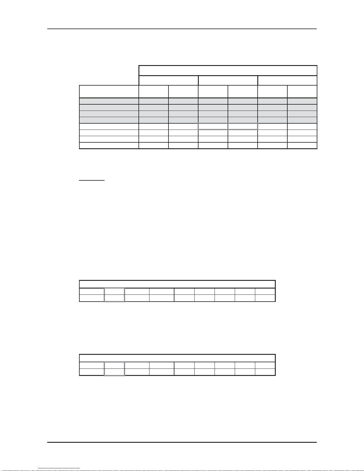
6.3 Outdoor units
MODEL SPL dB(A) SPW dB(A)
Indoor Outdoor Cooling/Heating Cooling/Heating
FLO7 ONG-7 46/47 56/57
FLO9 ONG-9 48/49 58/60
FLO12 ONG-12 52/53 62/64
FLO14 ONG-14 53/54 63/64
6.4 Sound Pressure Level Spectrum (Measured as Figure 5)
Cooling Heating
Figure 5. Microphone Distance from Unit
NC (Noise Criteria) Curves
NC15
NC20
NC25
NC30
NC35
NC40
NC45
NC50
NC55
NC60
NC65
10
20
30
40
50
60
70
80
90
63 125 250 500 1000 2000 4000 8000
Approximate
threshold of
rearing for
continuous
noise
Octave Band Sound Press. Level [dB re 20 mPa]
Octave Band Center Frequencies [Hz]
MODEL LINE
OU8-33
OU10-44
GC-18
GC-24
NC (Noise Criteria) Curves
NC15
NC20
NC25
NC30
NC35
NC40
NC45
NC50
NC55
NC60
NC65
10
20
30
40
50
60
70
80
90
63 125 250 500 1000 2000 4000 8000
Approximate
threshold of
rearing for
continuous
noise
Octave Band Sound Press. Level [dB re 20 mPa]
Octave Band Center Frequencies [Hz]
2/64
63/64
pectrum (Measured a
stance from Unit
NC
NC4
NC45
NC50
NC55
NC60
NC65
25 250 500 1000 2000 40
e
of
for
uous
e
e Band Center Frequencie
80
90
[dB re 20 mPa]
2/64
6
pe a
st
N
NC
C4
5
125 250 500 1000 2000 40
ate
d o
fo
nuo
e
e Band Center Frequencies
0
l [dB
available
Data is not aD
at
a
is
n
o
D
ata
is
no
Data is n
ta
ata
Dat
ta
ata
NN
a
vailable now
(Mea(Mea
om Unit Uni
vava

7-1
ELECTRICAL DATA
Revision 0
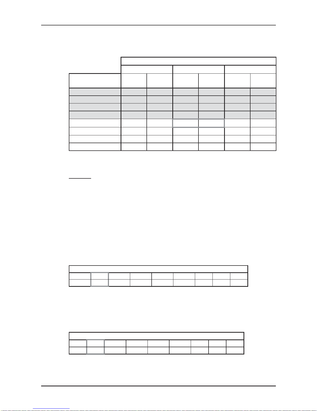
7. ELECTRICAL DATA
7.1 Single and Three Phase Units
MODEL FLO 7 N LCD FLO 9 N LCD FLO 12 N LCD FLO 14 N LCD
Power Supply
To indoor To indoor To indoor To indoor
1PH-230V-50Hz 1PH-230V-50Hz 1PH-230V-50Hz 1PH-230V-50Hz
Max Current, (A) 4.3 6.0 8.2 9.5
Circuit Breaker,(A) 10 10 15 15
Power Supply Wiring.
(No. x Cross Section mm
2
)
3x1.5 mm
2
3x1.5 mm
2
3x1.5 mm
2
3x1.5 mm
2
Interconnecting Cable RC
Model
(No. x Cross Section mm
2
)
5 x 1.0 mm2 + 2 x 0.5 mm
2
(OCT sensor)
5 x 1.0 mm
2
+ 2 x 0.5 mm2
(OCT sensor)
5 x 1.5 mm2 + 2 x 0.5 mm
2
(OCT sensor)
5 x 1.5 mm
2
+ 2 x 0.5 mm2
(OCT sensor)
Interconnecting Cable ST Model
(No. x Cross Section mm
2
)
4x1.0 mm
2
4x1.0 mm
2
4x1.5 mm
2
4x1.5 mm
2
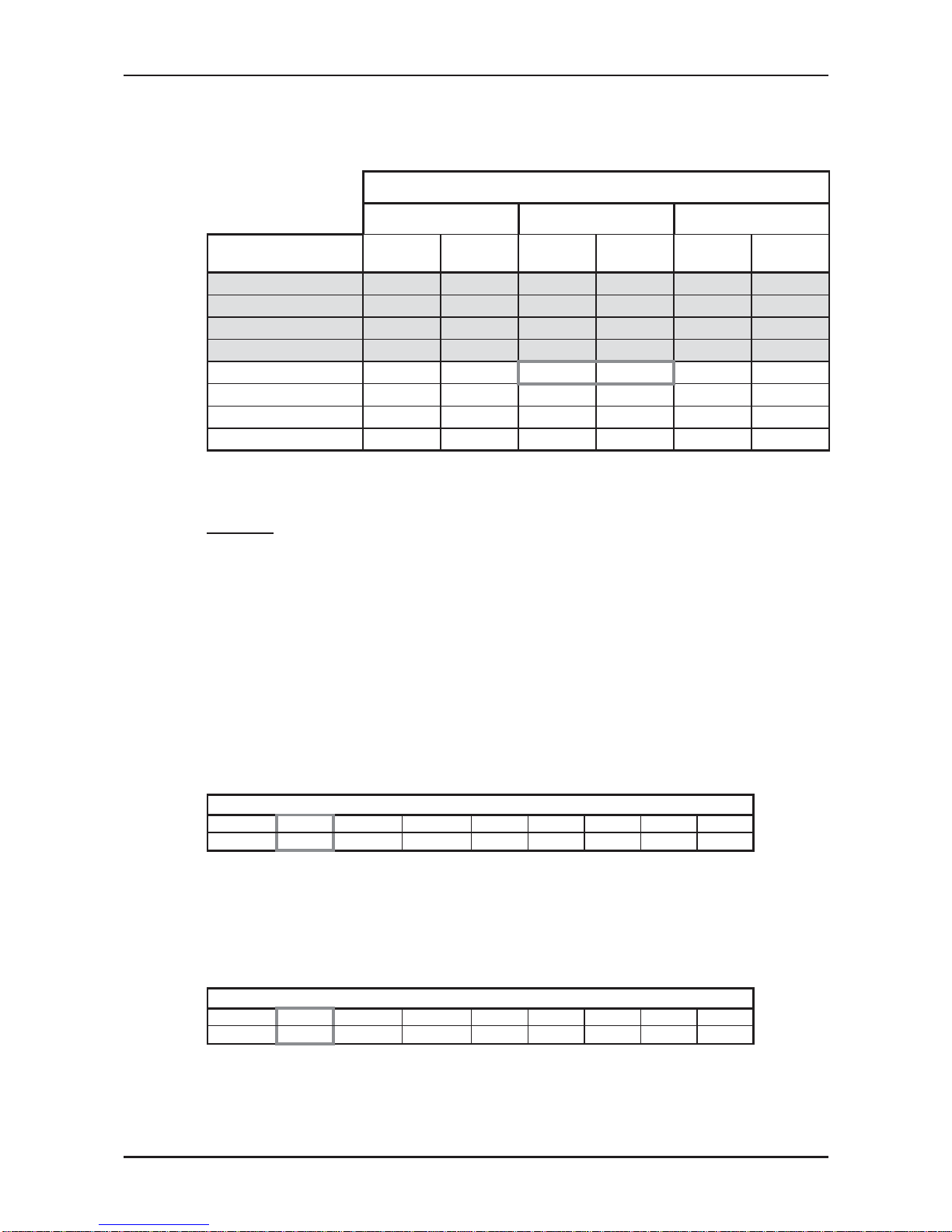
MODEL FLO 18 N LCD FLO 24 N LCD FLO 24 N LCD FLO 24 N LCD
Power Supply
To indoor To indoor(Option) To Outdoor To Outdoor
1PH-230V-50Hz 1PH-230V-50Hz 1PH-230V-50Hz 3PH-400V-50Hz
Max Current, (A) 11.1 14 14 3x6
Circuit Breaker,(A) 15 20 20 3x10
Power Supply Wiring.
(No. x Cross Section mm
2
)
3 x 1.5 mm
2
3 x 2.5 mm
2
3 x 2.5 mm
2
5 x 1.5mm
2
Interconnecting Cable RC Model
(No. x Cross Section mm2 )
5 x 1.5 mm2 + 2 x 0.5 mm2
(OCT sensor)
5 x 2.5 mm2 + 2 x 0.5 mm2
(OCT sensor)
6 x 2.5 mm2 + 2 x 0.5 mm2
(OCT sensor)
6 x 2.5 mm2 + 2 x 0.5 mm2
(OCT sensor)
Interconnecting Cable ST Model
(No. x Cross Section mm
2
)
4 x 1.5 mm
2
4x2.5 mm
2
+ 2x0.5 mm25x2.5 mm2 + 2x0.5 mm
2
5 x 2.5 mm2 + 2 x 0.5mm
2
(OCT sensor)
MODEL FLO 30 N LCD FLO 30 N LCD
Power Supply
To Outdoor To Outdoor
1PH-230V-50Hz 3PH-400V-50Hz
Max Current, (A) 17 3x9.2
Circuit Breaker,(A) 25 16
Power Supply Wiring.
(No. x Cross Section mm
2
)
3 x 4mm
2
5 x 2.5mm
2
Interconnecting Cable RC Model
(No. x Cross Section mm
2
)
6x2.5 mm2 + 2x0.5 mm2
(OCT sensor)
6 x 1.5 mm
2
+ 2 x 0.5 mm
2
(OCT sensor)
Interconnecting Cable ST Model 5 x 2.5 mm
2
+ 2 x 0.5 mm2 5 x 1.5 mm2 + 2 x 0.5 mm
2
(No. x Cross Section mm
2
)
(OCT sensor) (OCT sensor)
NOTE

8-1
WIRING DIAGRAMS
Revision 0
8. WIRING DIAGRAMS
NOTE
Wiring diagram lables as shown on units.
8.1 Indoor Unit FLO 7,9,12,14 N LCD

8-2
WIRING DIAGRAMS
Revision 0
8.2 Indoor Unit FLO 18, 24 N LCD

8-3
WIRING DIAGRAMS
Revision 0
8.3 Indoor Unit FLO 30 N
8-4
WIRING DIAGRAMS
Revision 0
8.4 Outdoor Unit GC18 1PH R410A
8.5 Outdoor Unit GC 24 1PH R410A
VT
VT

8-5
WIRING DIAGRAMS
Revision 0
8.6 Outdoor Unit ONG7 1PH R410A

8-6
WIRING DIAGRAMS
Revision 0
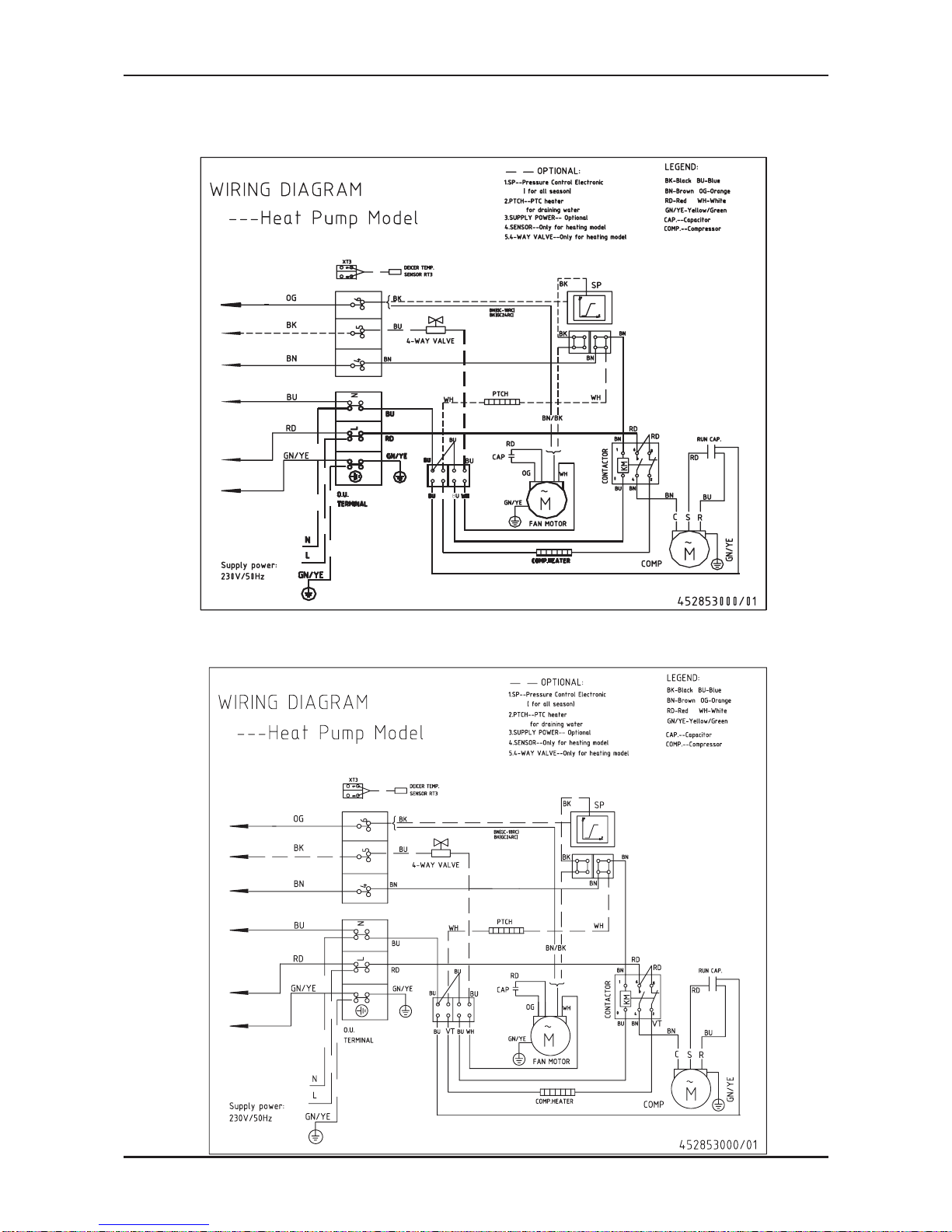
8.7 Outdoor Unit OU7-24/OU8-30 1PH R410A

8-7
WIRING DIAGRAMS
Revision 0
8.8 Outdoor Unit OU7-24/OU8-30 3PH R410A
8.9 Outdoor Unit OU8-33 1PH R410A

8-8
WIRING DIAGRAMS
Revision 0
8.10 Outdoor Unit OU8-33 3PH R410A

9-1
ELECTRICAL CONNECTIONS
Revision 0
9. ELECTRICAL CONNECTIONS
9.1 FLO-N- 7/9/12/14/18/24 1PH
9.2 FLO N - 24/30 1PH (power supply to outdoor unit)

9-2
ELECTRICAL CONNECTIONS
Revision 0
9.3 FLO - 30 N 3PH

10-1
REFRIGERATION DIAGRAMS
Revision 0
10. REFRIGERATION DIAGRAMS
10.1 Heat Pump Models
10.1.1 FLO-7-N

10-2
REFRIGERATION DIAGRAMS
Revision 0
10.1.2 FLO 9/12/14 N R410A

10-3
REFRIGERATION DIAGRAMS
Revision 0
10.1.3 FLO
-18-N R410A
Strainer
Strainer
valve
Check
Capillary
tube
Capillary
tube
tube
Capillary
tube
Capillary
Sensor
Indoor coil
connection
Flared
Valves
port
Service
Compressor
valve
Reverse
Strainer
Outdoor coil
Sensor
Indoor coil
Sensor
connection
Flared
Valves
port
Service
Compressor
valve
Reverse
Strainer
Outdoor coil
Sensor
Check
valve
INDOOR UNIT
OUTDOOR UNIT
HEATING MODE
COOLING MODE
INDOOR UNIT
OUTDOOR UNIT

10-4
REFRIGERATION DIAGRAMS
Revision 0
10.1.4 FLO
-24-N R410A

10-5
REFRIGERATION DIAGRAMS
Revision 0
10.1.5 FLO 30 N OU8-30 R410A
OUTDOOR UNIT
OUTDOOR UNIT
INDOOR UNIT
INDOOR UNIT
HEATING MODE
COOLING MODE

11-1
TUBING CONNECTIONS
Revision 0
11. TUBING CONNECTIONS
TUBE (Inch)
TORQUE (Nm)
¼” ⅜” ½” ⅝” ¾”
Flare Nuts 11-13 40-45 60-65 70-75 80-85
Valve Cap 13-20 13-20 18-25 18-25 40-50
Service Port Cap 11-13 11-13 11-13 11-13 11-13
1. Valve Protection Cap-end
2. Refrigerant Valve Port (use Allen wrench to open/close)
3. Valve Protection Cap
4. Refrigerant Valve
5. Service Port Cap
6. Flare Nut
7. Unit Back Side
8. Copper Tube
When the outdoor unit is installed above the indoor unit an oil trap is required every 5m along the suction
line at the lowest point of the riser. Incase the indoor unit is installed above the outdoor, no trap is
required.

12a-1
CONTROL SYSTEM
Revision 0
12.A CONTROL SYSTEM FLO 30 N
12A.1. Electronic Control
12A.1.1. Introduction
The electronic control information is designed for service applications, and is common
to the following groups of air-conditioners:
• ST/ RC group - Cooling only / cooling and heating by heat pump.
• SH group - Cooling and heating by heat pump and supplementary
heater.
• RH group - Cooling, heating by heaters only.
12Α.1.2. Jumpers Settings
GROUP J6 Setting J2 Setting
ST / RC Open Open
SH Closed Open
RH Closed Closed

12a-2
CONTROL SYSTEM
Revision 0
12A.2. Legend
12Α.2.1. Abbreviations
AC - Alternate Current
A/C - Air-Conditioner
ANY - ON or OFF status
CLOCK - ON/OFF Operation Input, (dry contact)
COMP - Compressor
CPU - Central Processing Unit
CTV -Compensation Temperature Value
ELUM - Extended Louver Upward Movement (Software Jumper)
E²PROM, EEP - Erase Enable Programmable Read Only Memory
HE - Heating Element
HPC - High Pressure Control
H/W - Hardware
ICP - Indoor Condensation Pump
ICT - Indoor Coil Temperature (RT2) sensor
IF, IFAN - Indoor Fan
IR - Infra Red
LEVEL1 - Normal Water Level
LEVEL2/3 - Medium/High Water Level
LEVEL4 - Overflow Level
Max - Maximum
Min - Minimum
min - Minute (time)
NA - Not Applicable
OCP - Outdoor Condensation Pump
OCT - Outdoor Coil Temperature (RT3) sensor
OF, OFAN - Outdoor Fan
OPER - Operate
Para. - Paragraph
RAT - Return Air Temperature (RT1) sensor
RC - Reverse Cycle (Heat Pump)
R/C - Remote Control
RCT - Remote Control Temperature
RH - Resistance Heater
RT - Room Temperature (i.e. RCT in IFEEL mode, RAT otherwise)
RV - Reversing Valve
SB, STBY - Stand-By
Sec - Second (time)
Sect - Section
SH - Supplementary Heater
SPT - Set Point Temperature
ST - Standard (a Model with Cooling Only)
S/W - Software
TEMP - Temperature
W/O - Without
WVL - Water Valve
∆T - The difference between SPT and RT.
In Heat Mode: ∆T = SPT - RT
In Cool/Dry/Fan Mode: ∆T = RT – SPT

12a-3
CONTROL SYSTEM
Revision 0
12A.3. Main PCB Controller
12Α.3.1. Display Board
Display (LEXAN) Display PCB Ass’y
OPR’ (STBY RED; ON: GREEN)
TIMER
FILTER LED
LCD SCREEN
FRESH, ION / ESF
RECIVER
OPR’ (STBY RED; ON: GREEN)
FRESH, ION / ESF
LCD SCREEN
RECIVER
TIMER
FILTER LED
FLO24/30

12a-4
CONTROL SYSTEM
Revision 0
12Α.3.2. List of A/C Models
The model is divided by IFAN speed of PG motor.
Model Type IFAN Speed
FLO 30 N Wall Mounted
Low : 900 rpm
Medial : 1050 rpm
High : 1300 rpm
Strong : 1350 rpm
WNG 25 Wall Mounted
Low : 750 rpm
Medial : 900 rpm
High : 1050 rpm
Strong : 1100 rpm
Note:
1. In this specification, the IFAN speeds of WNG25 and WNG28 are not decided by
the customer. It is only for reference.
2. The unit is only used in Wall mounted A/C.

12a-5
CONTROL SYSTEM
Revision 0
12Α.3.3. List of A/C Groups
The following table defines the different A/C groups, and the applicable operation
modes for each group.
Operating Mode ST RH RC SH
Fan Yes Yes Yes Yes
Cool
(3)
Yes Yes Ye s Yes
Heat
(3)
No Yes
(1)
Yes Yes
(2)
Dry
(3)
Yes Yes Ye s Yes
Auto Cool/Heat
(3)
No Yes
(1)
Yes Yes
(2)
Notes:
1. Electric heaters do the heating.
2. Heating is done by Compressor (Heat Pump), and by electric heaters.
12A.4. General functions
12Α.4.1. COMP operation
• For each Mode including POWER OFF & SB, a Min time delay of 3
min before COMP restarting, excluding DEICING Mode.
• The Min operation time of COMP under different operating conditions
is
Operation Mode
Min operation
time of COMP
Heat, Cool, H.P protection or Auto Modes 3 min.
Fan, Dry, Overflow, Protection modes, or mode change ignored

12a-6
CONTROL SYSTEM
Revision 0
12Α.4.2. IFAN operation
• Min time interval between IFAN speed changes in AUTOFAN Mode is 30 sec.
• Max time interval between IFAN speed changes in H/M/L Mode is 60 sec.
• Strong IFAN speed is only used in cool and heat mode and is controlled by R/C. Strong
IFAN cannot be remembered by EEPROM.
• IFAN speed in Heat/Cool and Auto fan Mode is determined according to the following
chart:
T [oc]
L
M
H
IFAN speed
3142
Where in Heat Mode: ∆T = SPT - RT
in Cool Mode: ∆T = RT- SPT
• IFAN uses PG motor and closed loop control.
12Α.4.3. OFAN operation
• Min time interval between OFAN ON/OFF state changes is 30 s.

12a-7
CONTROL SYSTEM
Revision 0
12Α.4.4. HE operation
• Minimum Heaters ON or OFF time is 30 sec.
• Heaters can never be in operation while IFAN is OFF.
• In RH group, HE-1 will be activated only when COMP is not operating except in Dry
Mode.
12Α.1.5. Protections
• High-pressure protection is applicable to all operating modes.
• Deicing control is valid in Heat and Auto Heat Mode only.
• Defrosting control is valid in Dry, Cool and Auto Modes.
• No reset after protection modes.
12Α.1.6. Thermistors operation
• Return air Temp is detected by RAT (RT1) in normal Mode, or by RCT (R/C sensor) in IFEEL Mode.
• ICT (RT2) detects indoor Coil Temp.
• Outdoor Coil Temp is detected by OCT (RT3).
• Definition of thermistor faults:
a. Thermistor is disconnected The thermistor reading is below -30
o
c.
b. Thermistor is shorted The thermistor reading is over 75
o
c.
c. Thermistor Temp reading doesn’t change (irrelevant for RT1) -

12a-8
CONTROL SYSTEM
Revision 0
12Α.1.7. RV Fault (comp units only)
This test is performed every time the unit is switched from OFF/STBY to OPER
in Heat mode or changes operation mode from COOL/DRY to HEAT (this
applies also in AUTO COOL/HEAT mode).
If ICT is lower than 35
0
C at the time of mode change, then at the first
occurrence of 15 min continuous COMP operation, ICT is compared with ICT
reading when the COMP was switched from OFF to ON 15 min before. RV fault
is defined when ICT decreases in more than 5
0
C.
In this case, the COMP will stop and the SB led will blink. This fault is reset after
going to SB or mode change.
12Α.1.8. Functional Mode Definitions
The following table summarized the models as they defined with accordance to
the jumper’s selection.
Model J4 J5
FLO 3 N 0 0
WNG-25 1 0
RESERVE 1 1

12a-9
CONTROL SYSTEM
Revision 0
12A.5. Cooling Mode
12Α.5.1. Cooling Mode – General
• Room Temperature, RT, is detected by
a) RAT in normal operation, or
b) RCT (R/C sensor) in I-FEEL mode.
• Indoor Coil Temp is detected by ICT (RT2).
• Outdoor Coil Temp is detected by OCT (RT3).
12Α.5.2. Control Functions
• COMP Operation
ON
OFF
RT-SPT
0
1
COMP
• OFAN Operation
a. In normal operation, OFAN operates together with the COMP.
• IFAN Operation
a. IFAN will operate in ANY speed regardless the ICT or COMP state.
b. IFAN speed will be determined according to user selection or AUTO-FAN logic.
• RV and HEATERS outputs
a. RV and HEATERS are in OFF state in cool mode.

12a-10
CONTROL SYSTEM
Revision 0
12Α.5.3. Sequence Diagrams
• Maintaining room temp at desired level by comparing RT and SPT with user defined IFAN
speed.
(RT - SPT) [oc]
+3
+2
+1
0
-1
-2
ON
OFF
ON
OFF
USER FAN SPEED
ON
OFF
COMP
(WVL)
OFAN
IFAN
RV
Note:
1) IFAN is always running at High, Medium, Low or Strong speed selected by user.
2) In IFEEL mode, the Room Temperature (RT) is the RCT from a R/C. Otherwise, the
RT is the RAT from the Room Thermistor.

12a-11
CONTROL SYSTEM
Revision 0
• Maintaining room temp at desired level by comparing RT and SPT with AUTO-IFAN.
(RT - SPT) [oc]
+4
+3
+2
+1
0
-1
-2
ON
OFF
ON
OFF
H
L
M
ON
OFF
COMP
(WVL)
OFAN
IFAN
RV

12a-12
CONTROL SYSTEM
Revision 0
12A.6. Heating Mode
112Α.6.1. Heating Mode - General
• Compensation Procedure:
The compensation procedure comes to solve the problem of the temperature
distribution by height during heat mode according to this procedure.
• When I feel is OFF during heat mode: RT= RAT – CTV.
When I feel is ON during heat mode: RT= RCT.
• CTV is a compensation temperature value to be used from the following table (CTV
table).
• RCV is a reference compensation value (relation between cells).
• IOC is a compensation value when IFAN is OFF.
• The values of RCV and IOC to be set in the following table are taken from the RCV
and IOC table below depending on the model.
CTV table:
I IFAN
ICT
OFF LOW MEDIUM HIGH
40 > ICT IIOC RRCV+0 RRCV+0 RRCV+0
50 > ICT ≥ 40 IIOC RRCV+0 RRCV+0 RRCV+0
ICT ≥ 50 IIOC+1 RRCV+1 RRCV+1 RRCV+1
RCV and IOC table
• The following table includes the RCV and IOC default values. These values are
set as values in the above compensation table.
Model RCV IOC
FLO 30 N +2
o
C+2
o
C
WNG-28 +2
o
C+2
o
C
WNG-25 +2
o
C+2
o
C
No compensation will be activated in Forced operation modes.

12a-13
CONTROL SYSTEM
Revision 0
12Α.6.2
. IFAN operation rules for RC and SH.
• As a general rule for RC and SH groups,
IFAN will be switched ON according to the following graph:
Note 1:
When ICT is faulty:
When the compressor switches from off to on (excluding deicing), IFAN will be on in
ANY speed.
When the compressor switches from on to off, the IFAN will change to low speed for 30
seconds and then it will be off.
Note 2:
Once the compressor is ON, 6 min later, excluding protection modes, IFAN will be
forced to Low until it reaches the ANY speed, and then IFAN will operate according
to items and above. This rule can be re-performed only on the next compressor
restart.
• In SH or RC group, IFAN will operate for min 30 sec , after HE’s turned
off, where in a case it has to be OFF, it will be forced to low speed.
36
17
15
40
20
ANY
LOW
OFF
IFAN
ICT
45
25
Duct ed
General:
Window:
20
COMP ON

12a-14
CONTROL SYSTEM
Revision 0
12Α.6.3. Heaters operation rules for RC and SH groups
• For both RC and SH groups, Heaters versus ΔT is as the following:
OFF
ON
ON
OFF
HE1
HE2
1 2 3 4
T=SP-RT [oc]
• Operation rules for Heaters in RC group:
a. Heaters can be enabled only if IFAN is ON,.i.e IFAN is in higher
precedence than the Heaters.
b. Heaters will operate according to ΔT and the following graph:
32
20
20
15
50
ON
OFF
ICT
45
HE-1
&
HE- 2
General:
Window:

12a-15
CONTROL SYSTEM
Revision 0
12Α.6.4. OFAN Operation for RC and SH
• As a general rule for RC and SH groups, excluding protection modes,
OFAN starts with the compressor.
• When OFAN is then ON it will operate according to the following conditions:
a) OFAN operates together with the compressor.
b) When (RT ≥ SPT – 2) and ICT ≥ 50 the 4.7k Ohm resistor is not
connected to the OCT, OFAN will operate according to the following curve:
0 3
ON
OFF
OCT
OFAN

12a-16
CONTROL SYSTEM
Revision 0
112Α.6.5. Heating, RC or SH Group
Mode: Heat, Auto (at heating)
Temp: Selected desired temperature
Fan: STRONG, HIGH, MED, LOW
Timer: Any
I Feel: On or Off
Sequence Diagram
Maintains room temp. at desired level by comparing RAT or RCT to SPT.
(RT - SPT) [oc]
+2
+1
0
-1
-2
-3
-4
ON
OFF
ON
OFF
ON
OFF
COMP
(WVL)
HE1
HE2
ON
OFF
RV

12a-17
CONTROL SYSTEM
Revision 0
12Α.6.6. Heating, RC or SH Group with Auto fan
Mode: Heat, Auto (at heating)
Temp: Selected desired temperature
Fan: Auto
Timer: Any
I Feel: On or Off
Sequence Diagram
Maintains room temp at desired level by controlling COMP, IFAN and OFAN.
(RT - SPT) [oc]
+2
+1
0
-1
-2
-3
-4
ON
OFF
ON
OFF
ON
OFF
COMP
(WVL)
HE1
HE2
ON
OFF
RV

12a-18
CONTROL SYSTEM
Revision 0
12A.7. Automatic Cooling or Heating
12Α.7.1. Automatic Cooling or Heating - General
• Mode Definition
Mode: Auto
Temp: Selected desired temperature
Fan: Any (except STRONG)
Timer: Any
I Feel: On or Off
• Switching-temperature between Cooling and Heating is SPT ± 3oc.
• When the Auto Mode is started with SPT +/-0
o
c, the unit will not select Auto Heat
or Auto Cool mode immediately. Instead, the unit will be in a temporary Fan Mode
with IFAN operating at low speed. The proper Auto Heat mode or Auto Cool will be
started whenever the RT reaches SPT-1
o
c or SPT+1oc respectively.
• For RC & SH units, Mode change between Auto Heat & Auto Cool Modes is
possible only after the COMP has been OFF during the last T minutes.
Mode Change time, T
Auto Cool to Auto Heat 3 min
Auto Heat to Auto Cool 4 min
.
• When unit is changed form Cool/Dry mode to Auto Mode, the unit will continue to
operate at (Auto) Cool Mode until the conditions for switching from Auto Cool to
Auto Heat are satisfied.
Similarly, when unit is changed from Heat Mode to Auto Mode, the unit will continue
to operate at (Auto) Heat Mode until the conditions for switching from Auto Heat to
Auto Cool are satisfied.

12a-19
CONTROL SYSTEM
Revision 0
12Α.7.2. Sequence Diagrams
• Auto Cooling or Heating, RC or SH Groups
Maintains room temp at desired level by selecting between cooling and heating modes.
(RT - SPT) [oc]
+3
+2
+1
0
-1
-2
-3
-4
ON
OFF
ON
OFF
H/M/L/OFF
ON
OFF
ON
OFF
COMP
& OFAN
HE1
HE2
IFAN
RV
USER FAN SPEED H/M/L/OFF
Auto Cool Mode Auto Heat Mode
> 4 min > 3 min
> 3 min > 2 min
(3) (3)
(4)
(4)
Auto Heat Mode
Notes:
1) Refer to Sect. Error! Reference source not found. for the details of IFAN operation.
2) Refer to Sect 0 for the minimum mode-change delay from COMP/HEs OFF.
3) HE2 is not used

12a-20
CONTROL SYSTEM
Revision 0
12A.8. Dry Mode
• Dry, ST or RC group with any group settings
Mode: Dry
Temp: Selected desired temp
Fan: Low
Timer: Any
I FEEL: Any
Control function
Reduce room humidity with minimum temp ’fluctuations by operating in Cool Mode
with low speed IFAN.
Notes:
1. When Dry is ON, the COMP is forced OFF for 3.5 min (longer than the 3 min
Min COMP-Off time) after every 15 min of continuous COMP operation.
2. When Dry is OFF, the COMP is forced ON for 6 min (longer than the 3 min
Min COMP-On time) after every 15 min of continuous COMP OFF time.
3. When Dry is changed from ON to OFF or vice versa, the limits mentioned in
(1) & (2) are ignored. The COMP operation is only controlled by the 3 min Min OFF
time and 1 min Min ON time.
4. In Dry Mode, IFAN is LOW when COMP is ON, and is OFF when COMP is
OFF.
DRY
(RT - SPT) [oc]
+2
+1
0
-1
-2
ON
OFF
ON
OFF
LOW
OFF
DRY-ON
DRY-OFF
ON
OFF
Time [min]
10
20
30
40 50
Max 15 minutes
3.5
min
Note1
6 min
Note 2
COMP
& OFAN
HE1
& HE2
IFAN
RV
Max 15 minutes
5 minutes COMP
ON time

12a-21
CONTROL SYSTEM
Revision 0
12A.9. Protection
• Cooling Mode Protections
Indoor: Coil Defrost
Mode: Cooling, Dry, Auto
Temp: Selected desired temp.
Fan: Any
Timer: Any
I Feel: On or Off
Function: Protect the indoor coil from ice formation at low ambient temperature
ICT [oc]
+2
ON
OFF
ON
OFF
t1 t2 t3
COMP
OFAN
+1
+5
+14
0
-1
-6
ON
OFF
IFAN
t1
t1 = 5 min minimum for each COMP starting
t2 = OFAN cycling (alternate between ON and OFF every 30 sec) for 20 min maximum
t3 = COMP and OFAN stop for 10 min minimum

12a-22
CONTROL SYSTEM
Revision 0
12Α.9.1. High Pressure Protection
Mode: (Auto) Cooling or Dry
Temp: Selected desired temp.
Fan: Any
Timer: Any
I Feel: On or Off
Function:
To protect the COMP from the high-pressure built-up in the outdoor coil during
normal cooling operation, by changing the IFAN speed and switching OFF COMP.
OCT [oc]
Any
OFF
Any
ON
Any
Blink
ON
COMP
OFAN
IFAN
OPER
LED
52
55
61
66
L
COMP is forced OFF
OFAN is forced ON
IFAN forced
to LOW
68
OFAN follow operation of
COMP
Note:
1. The ICT is also monitored during Cool and Dry mode, in case the RV
control circuit is faulty. Whenever ICT reaches 70
o
c, which indicates a high
pressure in the indoor coil, the COMP will be forced off automatically. The
COMP can be turned on again only after the ICT is under 70
o
c again and after
the 3 min COMP ON delay time. The OPER LED will not blink in this case.

12a-23
CONTROL SYSTEM
Revision 0
12Α.9.2. Heating Mode Protections
• Outdoor coil Deicing (excluding RH Group)
Mode: Heating, Auto (at heating)
Temp: Selected desired Temp
Fan: Any
Timer: Any
I FEEL: Any
Function:
Protects the Outdoor coil from ice formation by controlling COMP & RV operation.
Scope
This new deicer is designed to operate at extreme temp conditions. The deicing
cycle could be triggered from:
1. OCT temp’ and time between two consecutive deicing cycles.
2. Detection of ice forming by change of the OCT temp’.

12a-24
CONTROL SYSTEM
Revision 0
• Deicing procedure
gp
OCT [oc]
ON
OFF
ON
OFF
ON
L
ANY
COMP
OFAN
RV
IFAN
DST
(DDT)
0
12
OFF
HEs are forced ON
DOC
ANY
ON
HE
36s 36s
DT
30s
max 12 min.
Note 3
DI (note 1)
DI (note 2)
30s
3 min 3 min
IFAN
OFF
ANY
HE
OFF
ANY
all SH units
except WAX
RC or WAX units
HEs are forced OFF
IFAN is forced to Low Speed
BLINK
ON
OPER
LED
Notes:
1. At the first COMP activation after SB or OFF, if
(OCT < 0
o
c), then DI = 10 min, else DI = 40 min.
2. In the following Deicing cycles, the time interval between two
Deicing cycles activation is between 30 to 80 min.
3. For RC group, IFAN is forced off,
4. For SH group, HEs are forced ON and IFAN is forced to
operate in Low speed, regardless to the ICT and difference
between RAT & SPT.
5. When jumper J7 is set, the DST value is -2°C.

12a-25
CONTROL SYSTEM
Revision 0
12Α.9.3. High pressure protection (excluding RH Group)
Mode: (Auto) Heating
Fan: Any
Timer: Any
I Feel: On or Off
Control Function
Protect the Compressor from high pressure by switching OFF the OFAN and COMP.
ICT [oc]
Any
Off
Any
Off
COMP
OFAN
52
55
61
66
COMP is forced OFF
67
OFAN is force
Off
ON
BLINK
OPER
LED
Notes:
1. IFAN, HE1 will be activated according to the relevant Heating Mode Sect.
2. In case of any malfunction in the relay control circuit, the OCT is also monitored during
Heating mode. Whenever OCT reaches 70
o
c, which indicates a high pressure in the
outdoor coil, the COMP will be forced off automatically. The COMP can be turned on
again only after the 3 min COMP ON delay and the OCT is under 70
o
c. The OPER LED
will not blink in this case.

12a-26
CONTROL SYSTEM
Revision 0
12A.10. Timer
Mode: Any
Temp. Selected desired temp
Fan: Any
Timer: Timer On, Timer Off
I Feel: On or Off
Function:
• Starts or stops the unit operation after pre-set time.
If RC-1 is used, the timer setting will be (0.5 - 24 Hr) from the moment the timer is
set. The minimum resolution is 30 minutes.
If RC-2 or later version of remote controls is used, the timer setting will be (0:00 -
23:50) real time with 10 minutes resolution.
• After power failure, all pre-set timers are cleared. The system is forced to STBY
mode. .
Note: If all timers are inactive, the system will not be forced OFF after the power failure.
The last OPER/STBY status will be loaded from the EEP instead.
• When the A/C receives any valid message from a R/C, the current ON/OFF timer
settings will be replaced by the new timer settings in the R/C message.
Note: The following timer related operations will not affect the A/C operating mode
(Heat/Cool/Auto/Dry/Fan) setting.
a. Set ON/OFF timer
b. Clear ON/OFF timer
c. R/C ON Timer is time-up
d. R/C OFF Timer is time-up
E.g. When a STBY A/C unit (with Cool Mode setting in its EEP) is turned on by the
ON-TIMER of an R/C with heat mode setting, the A/C will start in Cool Mode.
 Loading...