


KRT2

User & Installation manual
VHF- Communication Transceiver
Doc.-Nr:
DE-3000-800100e
KRT2
Revision 12.2
Jan. 2016
1 / 61
KRT2
VHF
Communication
Transceiver
P/N 100-(0002)-(800)
P/N 100-(1002)-(800)
Operation and Installation
Manual

User & Installation manual
VHF- Communication Transceiver
Doc.-Nr:
DE-3000-800100e
KRT2
Revision 12.2
Jan. 2016
2 / 61
Record of Revisions
Revision
Date Subject
1 06 Juni 2010 First issue
2 20 Sep 2010 Revision Stecker / Redaktionelle Änderungen
3 05 Feb 2011 Editorial update
4 04 Mai 2012 Cable-harness correction
5 16 Mai 2012 Software advantage for battery indication, error reports
6 19.Aug 2012 Hints for mic. Installation & intercom
7 Sept. 2012 Correction wiring
8 Dec. 2012 Dynamic Microphone GND-wiring
8.1, 8,2 Feb.2013 Text corrections
9 March 2013 Additional drawing, clarify microphone GND
9.1 March 2013 Text corrections
9.2 April 2013 Hints in drawings
9.3
Aug. 2013 Text corrections, new cable drawings
9.4 Okt. 2013 Text corrections
9.5 Nov. 2013 New favorites management
9.6 Mai 2014 Menu-limitation, PTT-Mic.-assignment, Installation limitations, Text
corrections, Mic.-AUTO-enhancement
9.7 Jun 2014 Hint for speaker installation
9.8 July 2014 Add chapter 6.6.2 and 6.8.3.1, add drawing motorglider
9.9 Nov 2014 Update Installation and Limitations Section.
10.0 Dec. 2014 New Display
11.0 May 2015 Specialty of two PTT
11.1 Jun 2015 Recommendation for SIT
11.2 July 2015 6.8.3.2 Schematic correction (TX/RX)
11.3 Aug 2015 6.6.5 Supplement for speaker grounding
11.4 Sept 2015 4.4.2 Squelch explain
12.0 Oct. 2015 Extension for Mini & Portrait
12.1 Nov.2015 Hint for dynamic microphone
12.2 Dec. 2015 5.9.3.3 image correction
User & Installation manual
VHF- Communication Transceiver
Doc.-Nr:
DE-3000-800100e
KRT2
Revision 12.2
Jan. 2016
3 / 61
List of Service-Bulletins (SB)
Service-Bulletins have to be inserted in the manual, and entered in
the table.
SB Number
Rev.
No.
Date Issued
Date
Inserted
Name
Unit overview
Item No.
Product Overview
Basic Version
Introduction of::
•
2 Standard Microphone Inputs
•
Auxiliary Audio Input
•
DUAL Watch Function

User & Installation manual
VHF- Communication Transceiver
Doc.-Nr:
DE-3000-800100e
KRT2
Revision 12.2
Jan. 2016
4 / 61
TABLE OF CONTENTS
1 GENERAL .......................................................................................................................... 6
1.1 Symbols ........................................................................................................................... 6
1.2 Abbreviations .................................................................................................................. 6
1.3 Customer Service ............................................................................................................. 7
1.4 KRT2 Transceiver properties .......................................................................................... 7
1.5 Installation ....................................................................................................................... 8
1.6 Software ........................................................................................................................... 8
2 CONTROL general ............................................................................................................. 9
2.1 Control Elements Overview ............................................................................................ 9
2.2 Display ........................................................................................................................... 12
2.3 Audio Menu levels ........................................................................................................ 13
2.4 Self-test error reports ..................................................................................................... 14
3 OPERATION .................................................................................................................... 15
3.1 General........................................................................................................................... 15
3.2 ON / OFF Switching ...................................................................................................... 15
3.3 Frequency Selection ...................................................................................................... 16
3.3.1 Direct Frequency Selection .................................................................................... 16
3.3.2 Frequency Selection from the Favorites List ......................................................... 17
3.3.3 Storing and Editing Favorites ................................................................................. 17
3.4 AUD – Audio Menu ...................................................................................................... 20
3.4.1 VOL – Volume ....................................................................................................... 20
3.4.2 SQ -- Squelch ......................................................................................................... 20
3.4.3 VOX – Intercom Voice Trigger Level Setting ....................................................... 21
3.4.4 Manual Intercom ..................................................................................................... 21
3.4.5 TXm – PTT Switch Selection ................................................................................ 22
3.4.6 INT – Intercom Volume ......................................................................................... 22
3.4.7 EXT – External Audio Input Volume .................................................................... 22
3.4.8 DIM – Display Brightness ...................................................................................... 23
3.4.9 BAT – Battery test .................................................................................................. 23
3.4.10 SIT – Side tone ....................................................................................................... 24
3.4.11 MIC – Setup ........................................................................................................... 24
3.4.12 Menu lock ............................................................................................................... 27
3.5 DUAL Watch ................................................................................................................. 27
3.6 Transmitter Operation.................................................................................................... 29
3.6.1 Speciality of two PTT ............................................................................................ 30
3.6.2 Self-test monitor ..................................................................................................... 30
3.6.3 Optical side tone ..................................................................................................... 31
3.7 Resetting to factory settings .......................................................................................... 32
3.8 SET UP - Menu ............................................................................................................. 32
3.8.1 ERASE – Erasing the Favorites List ...................................................................... 33
3.8.2 Channel Spacing ..................................................................................................... 33
4 Remote Control ................................................................................................................ 34
5 Installation ........................................................................................................................ 35
5.1 Limitations ..................................................................................................................... 35

User & Installation manual
VHF- Communication Transceiver
Doc.-Nr:
DE-3000-800100e
KRT2
Revision 12.2
Jan. 2016
5 / 61
5.2 Installation Hints ........................................................................................................... 36
5.3 Telecommunication Data ............................................................................................... 36
5.4 Scope of delivery ........................................................................................................... 36
5.5 Unpacking and Inspecting the Equipment ..................................................................... 37
5.6 Mounting ....................................................................................................................... 37
5.7 Electrical Connections ................................................................................................... 38
5.7.1 Microphone-Connection......................................................................................... 38
5.7.2 Speaker & open microphone: ................................................................................. 39
5.7.3 Earphone Connection ............................................................................................. 40
5.7.4 External Audio Input .............................................................................................. 40
5.7.5 Speaker Connection................................................................................................ 40
5.8 Final Audio-Setup ......................................................................................................... 41
5.8.1 For gliders .............................................................................................................. 41
5.8.2 For motor gliders dual seaters ................................................................................ 41
5.8.3 For Motor planes .................................................................................................... 41
5.9 Wiring ............................................................................................................................ 42
5.9.1 Wire Gauges ........................................................................................................... 42
5.9.2 Connector Pin-Configuration ................................................................................. 42
5.9.3 Wiring Diagram...................................................................................................... 42
5.9.3.1 Two place motor aircraft connection .............................................................. 42
5.9.3.2 Glider two place connection ........................................................................... 44
5.9.3.3 Glider single .................................................................................................... 45
5.9.3.4 Motor glider single .......................................................................................... 46
5.9.3.5 Motor glider dual ............................................................................................ 47
5.9.4 Wiring for dynamic microphones .......................................................................... 49
5.9.5 Connection support ................................................................................................ 49
5.10
Antenna ...................................................................................................................... 50
5.10.1 Antenna Selection .................................................................................................. 50
5.10.2 Installation Recommendation ................................................................................. 50
5.11
Microphone general ................................................................................................... 51
5.12
Post-Installation Check .............................................................................................. 52
5.13
Starting Up ................................................................................................................. 53
5.14
Accessories ................................................................................................................ 53
5.15
Drawings .................................................................................................................... 54
5.15.1 Dimensions ............................................................................................................. 54
5.15.2 Installation Directions ............................................................................................ 55
6 Maintenance ..................................................................................................................... 56
6.1 Periodic Maintenance .................................................................................................... 56
6.2 Repair ............................................................................................................................ 56
6.3 Cleaning ......................................................................................................................... 56
7 ANNEX ............................................................................................................................. 57
7.1 Frequency / Channel- schedule ..................................................................................... 57
7.2 Technical Data ............................................................................................................... 58

User & Installation manual
VHF- Communication Transceiver
Doc.-Nr:
DE-3000-800100e
KRT2
Revision 12.2
Jan. 2016
6 / 61
1 GENERAL
This manual contains information about the physical, mechanical and
electrical properties as well as a description for the operation and
installation of the VHF airborne transceiver KRT2.
1.1 Symbols
WARNING
Non-compliance may cause personnel injury due to radiation
or fire.
CAUTION
Non-compliance may cause damage or incorrect operation of
the transceiver.
INFORMATION
1.2 Abbreviations
Abb
Description
Definition
PTT Push to Talk
Transmitter activation
VOX Voice operated intercom
Voice level setting for intercom
activation
INT Intercom level
Intercom volume level setting
SQ Squelch
Squelch setting
DIM Dimming
Display brightness setting
BAT Battery control
Check DC source
EXT External audio input
External Audio input level setting

User & Installation manual
VHF- Communication Transceiver
Doc.-Nr:
DE-3000-800100e
KRT2
Revision 12.2
Jan. 2016
7 / 61
1.3 Customer Service
In order to process returned units most expeditiously, please fill in the
form Reshipment to be found under Service at http://www.dittel-
avionik.de.
Suggestions which will improve this manual are very much
appreciated at: http://www.dittel-avionik.de.
Information concerning software updates are available under
AIRplus
Avionics at
http://www.dittel-avionik.de.
1.4 KRT2 Transceiver properties
•
VHF airborne transceiver
•
Frequency range 118,000 to 136,975 MHz
•
Channel spacing 8,33/25 kHz (2278 channel)
•
Fast channel selection
•
4 separate microphone inputs (2 x standard or 2 x dynamics)
•
Audio-input for other audio devices
•
Installation: Standard panel cut-out (57 mm)
•
100 user definable frequencies with up to 8 character identifiers
Continuous transmissions will be turned off after 2 minutes.
(Stuck mic function)

User & Installation manual
VHF- Communication Transceiver
Doc.-Nr:
DE-3000-800100e
KRT2
Revision 12.2
Jan. 2016
8 / 61
1.5 Installation
For installation hints, data, electrical connections, limitations and
mounting instructions please see section “5 Installation”.
1.6 Software
The most functions inside the transceiver are controlled by
microprocessors. The software is classified as Level D in accordance with
EUROCAE/RTCA document ED12B/DO-178B.

User & Installation manual
VHF- Communication Transceiver
Doc.-Nr:
DE-3000-800100e
KRT2
Revision 12.2
Jan. 2016
9 / 61
2 CONTROL general
2.1 Control Elements Overview
User & Installation manual
VHF- Communication Transceiver
Doc.-Nr:
DE-3000-800100e
KRT2
Revision 12.2
Jan. 2016
10 / 61
All functions and performances between the normal size unit (57mm
round) and the Portrait format (Mini) are identical.
The only difference to the Mini is partly the arrangement of the text area on
the display.

User & Installation manual
VHF- Communication Transceiver
Doc.-Nr:
DE-3000-800100e
KRT2
Revision 12.2
Jan. 2016
11 / 61
ON
ON / OFF
Self-locking switch
DUAL
DUAL WATCH
1. Scanning between the Active and Standby
frequencies
2. Positioning cursor to the left when
programming the station identifier
AUD
AUDIO
SELECT
1. Stepping through the audio menus VOL SQ
VOX TX INT EXT DIM CON SIT and MIC
2. Positioning cursor to the right when
programming the station identifier
MEM
FAVORITES
1. Frequency and identifier selection from the
favorites list
2. Programming of favorites (frequency and
identifier)
EXCHANGE
Exchange of the
Active and Standby
frequencies
TURNING
KNOB
Pressing for Selection of the frequency range to:
MHz, 100kHz, 10kHz
Toggles between frequency and identifier when
programming the favorites
Sets all variable values in any menu
1. Volume setting of headsets and speakers
2. MHz/kHz selection of the standby
frequency in 3 different ranges
3. Favourite selection
4. Alpha character selection when
programming favorites
5. Change of microphone settings
User & Installation manual
VHF- Communication Transceiver
Doc.-Nr:
DE-3000-800100e
KRT2
Revision 12.2
Jan. 2016
12 / 61
2.2 Display
Indication
Meaning
Remarks
RX
Reception
RX is displayed during
reception (squelch opened)
TX
Transmission
Transmitter operates
normally
Te
Transmitter was turned
off automatically after 2
min continuous operation
119.700
Active frequency
ZELL SEE
Active frequency station
identifier
Displayed when frequency
and identifier are stored in
the favourite list
VOL ……
Receiver volume level
(default after a certain time
delay)
When AUD was pressed
the corresponding Audio
Menu item and setting is
displayed
DUAL
Active frequency AND
Standby Frequency are
monitored simultaneously
DUAL function is
deactivated by frequency
change or by pressing the
DUAL button again
MEM
Favourite list index
(0-99)
When frequency and
identifier are stored at this
index they are displayed
119.700
upper
Active - frequency
125.800
lower
Standby/DUAL - frequency
<
The pointer indicates what
the turning knob will change
VOL SQ VOX…..etc
Arrow is positioned in
according to the button
pressed
( AUD or FREQ)
BAT
Supply voltage is low
<10,5V
Battery low or
Battery/Generator faulty

User & Installation manual
VHF- Communication Transceiver
Doc.-Nr:
DE-3000-800100e
KRT2
Revision 12.2
Jan. 2016
13 / 61
A-match Antenna error Bad antenna match
a v e
Status of certain Audio
menu functions
a = AUX. Input active
v = VOX active
e = external Intercom
switch active
MUC IN
Standby frequency station
identifier
Displayed when frequency
and identifier are stored in
the favourite list
2.3 Audio Menu levels
Displayed Signification Remarks
VOL
Volume
Default level
SQ
Squelch
VOX
Voice operated intercom
DIM
Display brightness
BAT
DC source check
INT
Intercom - Volume
EXT
Volume of external devices
TX**
PTT button selection
Left/Right/Both
SIT
Side tone
During transmitter operation
MIC
SetUp-Menu for
Mikrophones
Service-Menu without radio
operation.
User & Installation manual
VHF- Communication Transceiver
Doc.-Nr:
DE-3000-800100e
KRT2
Revision 12.2
Jan. 2016
14 / 61
2.4 Self-test error reports
Display
Meaning
Remark
Er_PLL
Internal error, no
transmission
Return the transceiver for
maintenance
Er_ADC
Internal error,
Return the transceiver for
maintenance
Er_FPA
Internal error; unit not
usable
Return the transceiver for
maintenance
Er_I2C
Internal error; unit not
usable
Return the transceiver for
maintenance
Er_si53
Internal error; unit not
usable
Return the transceiver for
maintenance
Er_D10
Internal error;
reception corrupt
Return the transceiver for
maintenance
Key_Block
Internal error; unit not
usable
Return the transceiver for
maintenance
User & Installation manual
VHF- Communication Transceiver
Doc.-Nr:
DE-3000-800100e
KRT2
Revision 12.2
Jan. 2016
15 / 61
3 OPERATION
3.1 General
In the normal operating mode in which the turning knob always is
connected to the volume (VOL). The normal operating mode can be left by
pressing the AUD, FREQ or MEMORY button.
When not in the normal mode and there is no pilot action for more than 10
seconds the unit returns to the normal mode.
3.2 ON / OFF Switching
ON / OFF switching is done by pushing the self-locking switch.
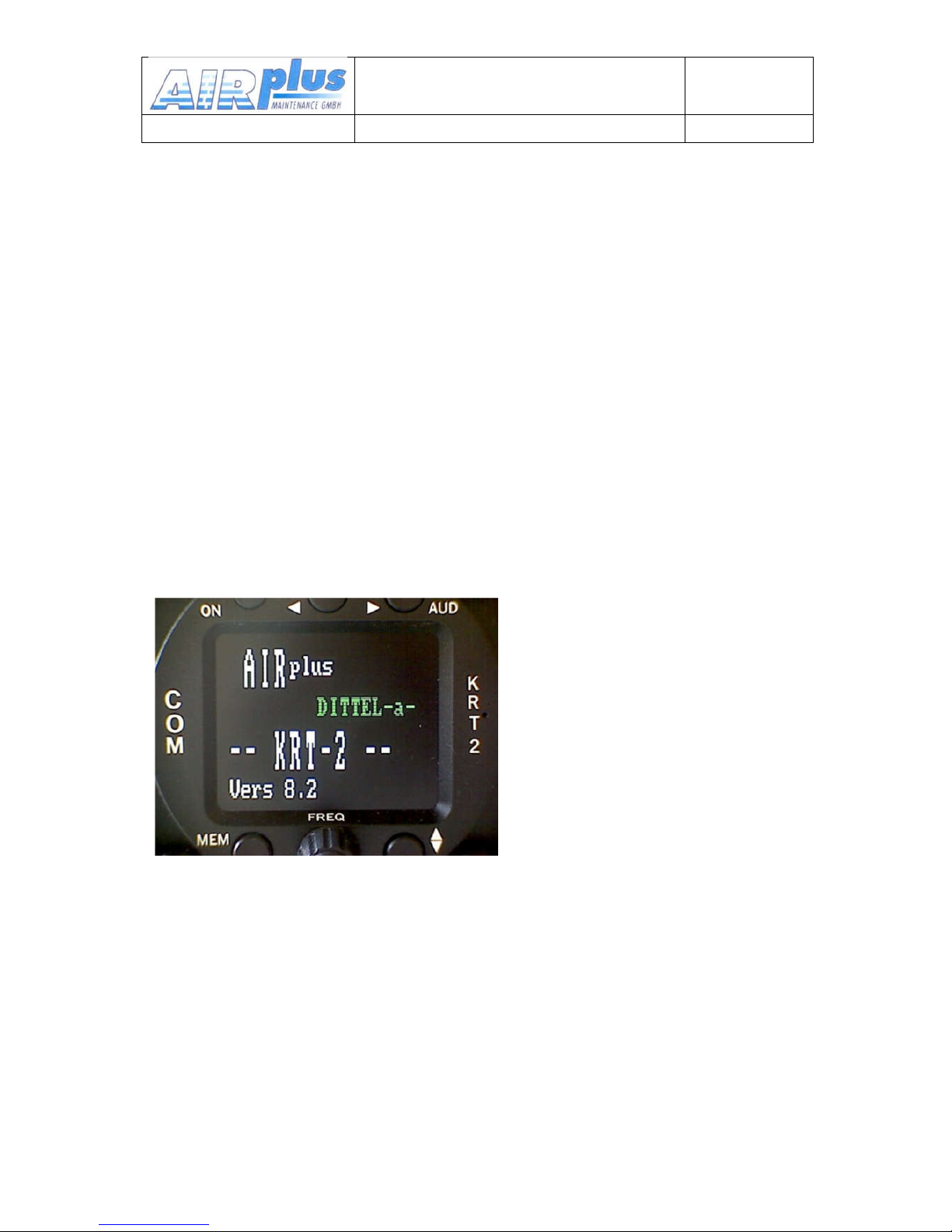
After power up the following display will be displayed:
Device-name
KRT2
Software-
Version e.g. V8.2
(example)
The unit then starts in the normal operating mode using and displaying the
data last used.
User & Installation manual
VHF- Communication Transceiver
Doc.-Nr:
DE-3000-800100e
KRT2
Revision 12.2
Jan. 2016
16 / 61
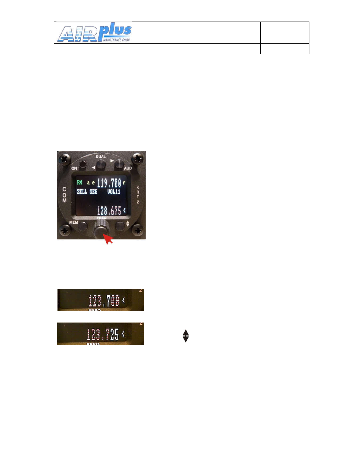
3.3 Frequency Selection
There are two different frequency selection methods:
• Direct Input
• Selection from the favourite list (index 0-99)
3.3.1 Direct Frequency Selection
The Standby-Frequency is set with
the turning knob in 3 different ranges.
The selected range is highlighted and
can be changed with the FREQ
button.
Frequency ranges are:
1xx.nnn
1nn.xnn
1nn.nxx
Press the FREQ button once or
several times until the desired
frequency range is highlighted.
The unselected digits are displayed
as dotted digits.
When the pointer is not next to the
Standby Frequency window, it will
be repositioned with the first
pressing of the FREQ button.
exchanges the Active and
Standby frequencies.
When the Exchange button was not pressed, the Standby frequency
display will return to its normal appearance after 20 seconds.

User & Installation manual
VHF- Communication Transceiver
Doc.-Nr:
DE-3000-800100e
KRT2
Revision 12.2
Jan. 2016
17 / 61
3.3.2 Frequency Selection from the Favorites List
By pressing MEM and operating the turning knob a specific favourite list
position can be accessed [xx] (xx = index 0 … 99). When frequency and
station identifier have been defined, they will be displayed in the
Standby and station identifier windows.
The favourite identifiers list identifiers can be sorted in alphabetic order
(see 3.3.3 Storing and Editing Favorites).
exchanges the Active and Standby frequencies.
The selection procedure can be terminated with either the AUD or
FREQ buttons. Without pressing any of these buttons the unit will return
to its normal operating mode after 20 seconds.
3.3.3 Storing
and
Editing Favorites
Any displayed Standby Frequency can associated with an identifier and
both can be stored together as favorites in the favorite list. Both the
frequency and identifier of a favorite can be edited.
First press the MEM button and by means of the turning knob go to the
desired favourite list position which may be empty or the favourite to be
edited using the turning knob (index [00 …99]).
Press the MEMORY button a second time and „–EDIT--„ will show up in
the program window.

User & Installation manual
VHF- Communication Transceiver
Doc.-Nr:
DE-3000-800100e
KRT2
Revision 12.2
Jan. 2016
18 / 61
In the identifier window a
blinking cursor will show up
under the extreme left
character.
The turning knob selects
the desired character.
The AUD button positions
the curser one character to
the right. The DUAL button
positions the cursor one
character to the left and
simultaneously erases this
character.
The station identifier can consist of maximum 8 characters.
To change frequency just press the FREQ button and follow the normal
direct input procedure to edit the frequency.
To quite the frequency input press the MEMORY button again in order to
go to the station identifier window for editing the identifier if required.
Using the buttons FREQ and MEMORY it can be toggled any time
between identifier and frequency input.
Keep in mind the watch dog timer which will terminate the input mode
after 20 sec.
Termination / save
From the identifier mode pressing key, for short time “SAVE” will
appear and the system will go back to the favourite selection.
A sorting process can be activated by pressing MEMORY again from
the EDIT-mode.

User & Installation manual
VHF- Communication Transceiver
Doc.-Nr:
DE-3000-800100e
KRT2
Revision 12.2
Jan. 2016
19 / 61
SORT? will show up which stays for 20 seconds and it will be activated
with or skipped with MEMORY.
When activated all 99 favorites will sorted in alphabetical order and the
process can take several minutes.
During the sorting procedure „RUN nn“ is displayed in the program
window, with nn being the running index.
After skipping or ending the sort the transceiver then resumes its normal
operating mode.
When the MEMORY button is pressed at the time when „RUN nn“ is
displayed, the sorting procedure is terminated. The favourite list is then
sorted partially only and the transceiver resumes its normal operating
mode.
Example:
1.) Select location -> Button MEM SEL [23]
2.) Input of name -> Button MEM -EDIT-
Rotation knop to select character
For cursor use (AUD) (DUAL)
Frequency setting -> press knop
Use button MEM to go back to -EDIT-
3.) Saving press button , it appears shortly SAVE, then back to 1.)
4.) Sorting press button MEM, -> question for SORT, Yes = ,
No = MEM
Exit if do nothing.
Doing nothing for longer will cancel the edit mode without no saving.
Hints: Some software versions requiring a faster rotation to select.
 Loading...