

Page 1
WeatherCaster
WeatherStation® Instrument
Compass
™
Software Guide
with GPS Receiver
Heading Sensor
Smart™ Sensor
GPS Receiver
Compass
Record the version number found on the Airmar Sensor Support CD.
Version No.______________Date of Purchase_________________
17-460-01 rev. 05 02/20/12
Page 2

Copyright © 2007 - 2012 Airmar Technology Corp. All rights reserved.
All Rights Reserved. Except as expressly provided herein, no part of this manual may be
reproduced, copied, transmitted, disseminated, downloaded, or stored in any storage
medium, for any purpose without prior written consent of Airmar. Airmar hereby grants
permission to download a single copy of this manual and of any revision of this manual onto
a hard drive or other electronic storage medium to be viewed and to print one copy of this
manual or any revision hereto, provided that such electronic or printed copy of this manual
or revision must contain the complete text of this copyright notice and provided further that
any unauthorized commercial distribution of this manual or any revision hereto is strictly
prohibited.
Information in this manual is subject to change without notice. Airmar reserves the right to
change or improve its products and to make changes in the content without obligation to
notify any person or organization of such changes. Visit the Airmar website at
www.airmar.com for current updates and supplemental information concerning the use and
operation of this and other Airmar products.
Page 3

Table of Contents
Introduction and Sensor Functions.................................................. 4
Installing WeatherCaster™ Software...............................................5
Installing the Application..............................................................5
Installing the Drivers.....................................................................8
Setting Up WeatherCaster™ Software...........................................14
NMEA 0183 Interface.................................................................15
NMEA 2000® Interface.............................................................. 17
Using WeatherCaster™ Software.................................................. 23
Large Compass & Digital Readout Screen................................. 29
Advanced Setup—Firmware Settings............................................32
Sensor Hardware.........................................................................32
Enable/Disable Functionality............................................... 34
Sensor Orientation................................................................ 37
Sensor Options...................................................................... 40
Calibrate Compass................................................................ 44
Calibrate Paddlewheel.......................................................... 47
NMEA 2000® Settings..........................................................49
Restore Factory Defaults.......................................................50
Communications/Diagnostics.....................................................51
NMEA 0183 Interface...........................................................52
NMEA 2000
® Interface........................................................ 54
Alarms.........................................................................................56
Names......................................................................................... 58
Update Flash............................................................................... 60
Running Multiple Copies of WeatherCaster™ Software...............62
Updates & Troubleshooting...........................................................54
Appendix—Technical Information................................................ 68
3
Page 4

Introduction
WARNING
Navigation Aid Only—The WeatherCaster™ software is a
means to display weather and navigation data. It is an aid to
navigation only and should never be solely relied upon. It is
not a replacement for traditional navigation aids and
techniques. Only official government charts contain all the
information needed for safe navigation. As always, the enduser is responsible for their prudent use.
The WeatherCaster™ software allows you to communicate with your sensor(s)
through a personal computer when your installation includes a Converter or a
Combiner. Weather and navigation information is conveniently displayed on your
PC in both analog and digital formats. WeatherCaster software is designed to work
with the Microsoft
®
Windows® XP operating system.
Sensor Functions
The information displayed on the WeatherCaster screens will depend upon the
sensor(s) that is installed and selected. Your WeatherCaster software may display
some or all of the information below.
• Air temperature
• Apparent-wind direction
• Barometric pressure
•Dewpoint
• GPS satellites
• Heading
• Heat-index temperature
• Pitch and roll angle
• Relative humidity
•Time
• True-wind direction
• True-wind speed relative to speed through water
• Water depth
• Water speed
• Water temperature
• Wind-chill temperature
4
Page 5
Installing WeatherCaster™ Software
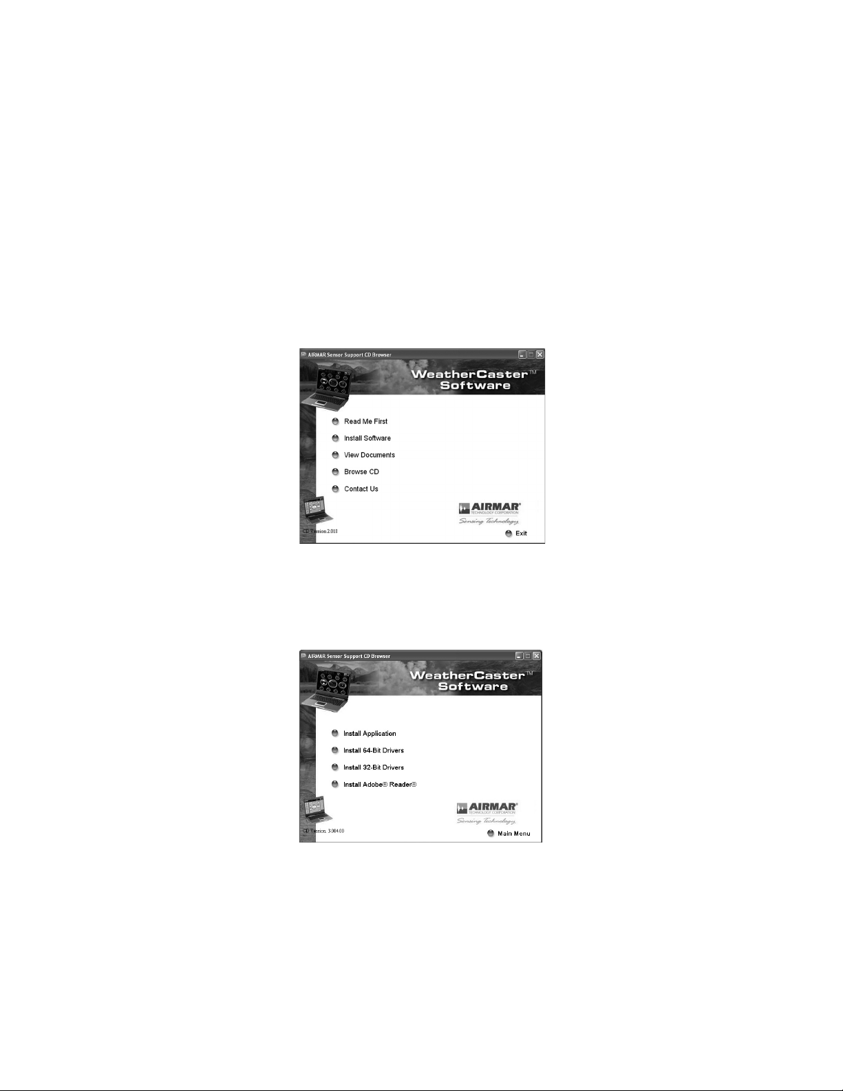
Figure 1. Sensor Support CD Browser window
Figure 2. Sensor Support CD Browser install window
CAUTION: The screen resolution must be set at 1024 x 768 pixels for the
WeatherCaster software to operate properly.
Installing the Application
1. Power your PC.
2. Insert the Airmar Sensor Support CD into the CD-ROM drive on your PC. The
Sensor Support CD Browser window will appear (see Figure 1).
Click the Install Software button.
3. A second Sensor Support CD Browser window will appear (see Figure 2).
Click the Install Application button.
5
Page 6
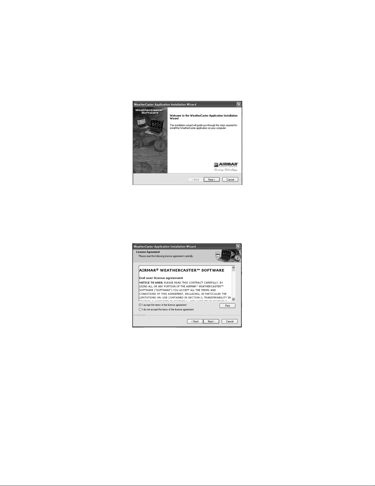
4. The WeatherCaster Installation Wizard window will appear (see Figure 3).
Figure 3. WeatherCaster Installation Wizard window
Figure 4. WeatherCaster License Agreement window
Click Next to continue.
5. The WeatherCaster License Agreement window will appear (see Figure 4).
Click the “I accept the terms of the license agreement” button to accept the
agreement, then click Next to continue.
6
Page 7
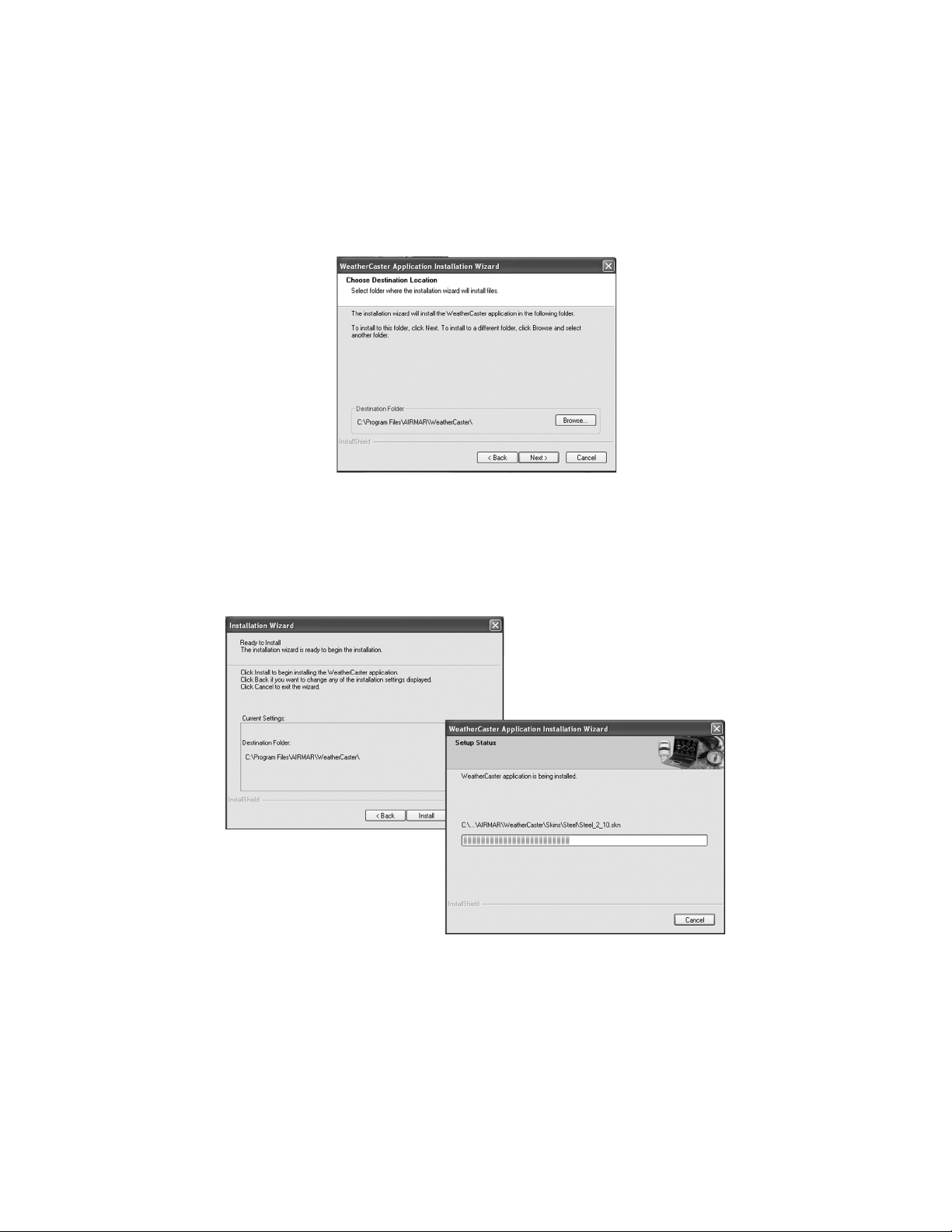
6. The Choose Destination Location window will appear (see Figure 5). Follow the
Figure 5. Choose Destination Location window
Figure 6. Ready to Install and Setup Status windows
screen prompts. Click Next to continue.
7. The Ready to Install window will appear (see Figure 6). Click Install. The Setup
Status window will be displayed while the WeatherCaster software is being
installed.
7
Page 8
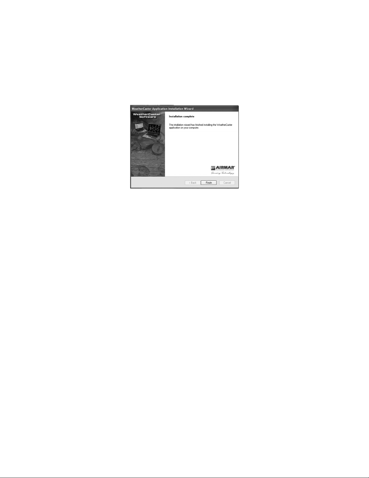
8. The Installation Complete window will appear when the WeatherCaster
Figure 7. Installation Complete window
software has been successfully installed (see Figure 7). Click Finish. The
Sensor Support CD Browser window will appear (see Figure 2).
NOTE: If you are replacing an older version of the WeatherCaster software with a
new one, you can begin using it now. Do NOT install the device drivers again.
Installing the Drivers
IMPORTANT: Be sure the Airmar Sensor Support CD is inserted into the CDROM drive on your PC before the Combiner or Converter hardware is connected.
CAUTION: The driver installation is in TWO parts. Both drivers must be
installed for the sensor to communicate with the WeatherCaster software.
CAUTION: If you are replacing an older version of the WeatherCaster software with
a new one, you can begin using it now. Do NOT install the device drivers again.
The first driver is the USB Controller Driver. It is needed to convert the USB data
packets to a serial data stream. The second driver, the USB Communications Port
Driver, makes the USB connection appear as a communications port in the
Windows Device Manager. Note that you must choose the set of drivers that are
compatible with the bit size of your operating system.
Choose 64 or 32-Bit Drivers
To determine the bit size of your operating system, go to Start\Settings\Control
Panel\System and view the General tab. If the operating system is 32 bits, it may
not be identified. However, if the operating system is 64 bits, it is probably identified.
If you are unable to determine the bit size of your operating system, choose Install
32-Bit Drivers first. If you see an error message saying your system requires the
64-bit version of DPInst.exe, then choose Install 64-Bit Drivers.
8
Page 9
Copying the Device Drivers to the PC
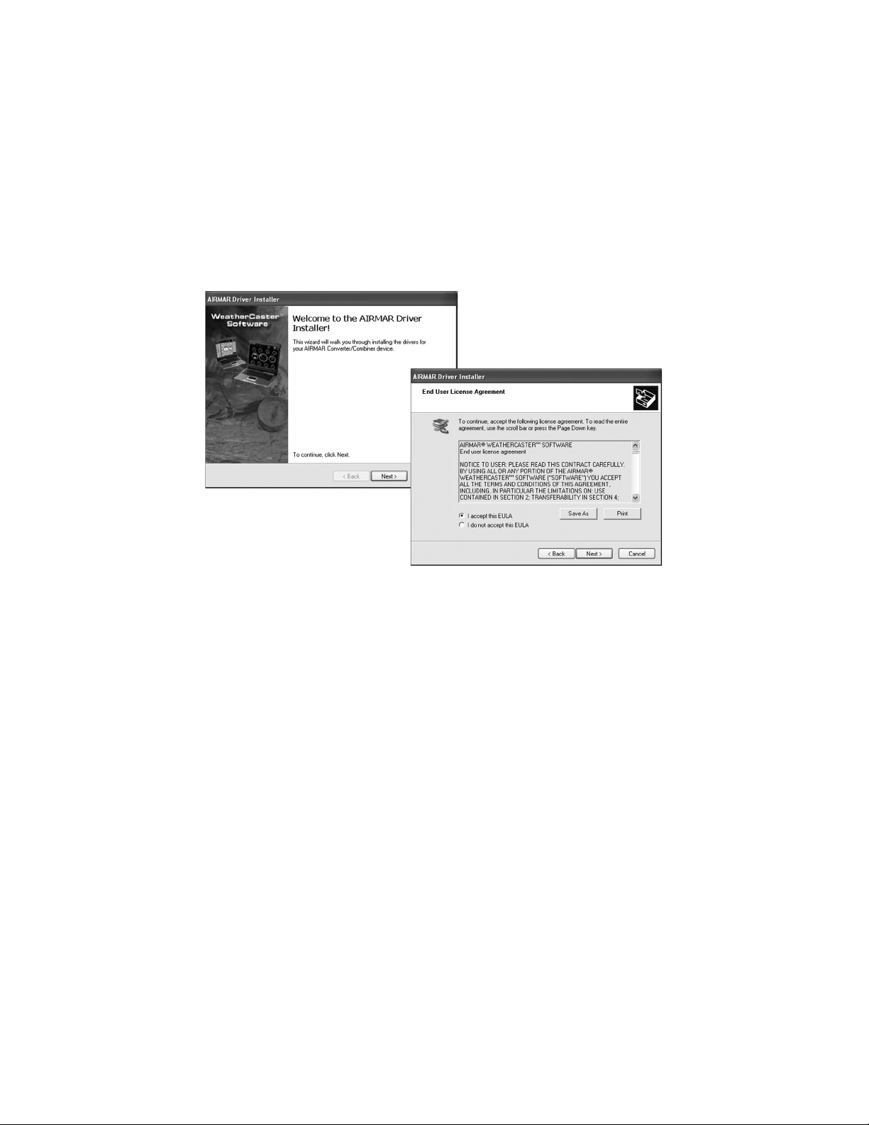
Figure 8. Driver Installer and End User License Agreement windows
1. The Sensor Support CD Browser window will appear (see Figure 2). Click the
appropriate Install Drivers button to begin the process of copying the Airmar
device drivers to your PC.
2. The Driver Installer window will appear (see Figure 8). Click Next to continue.
3. The End User License Agreement window will follow (see Figure 8). Click the
I accept this EULA button to accept the agreement. Click Next to continue.
9
Page 10
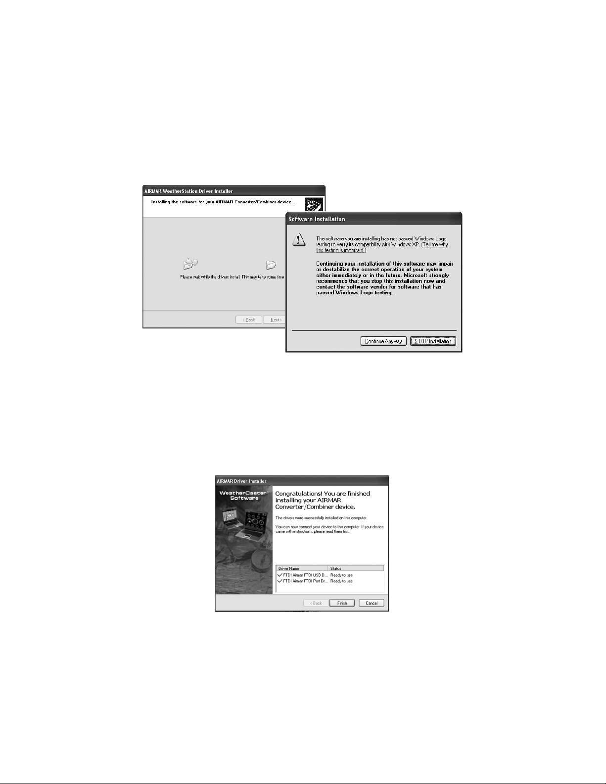
4. The Please Wait window followed by the Software Installation caution window
Figure 9. Please Wait and Software Installation caution windows
Figure 10. Congratulations window
will appear (see Figure 9). The drivers are not Microsoft Windows
®
certified.
However, they have been tested for stable and reliable operation. Click
Continue Anyway to proceed with the installation.
5. When the Language File Replace window appears, click No To All.
6. The Please Wait and the Software Installation caution windows will appear
again (see Figure 9). Click Continue Anyway to proceed with the installation.
7. Please wait while the copying takes place. When it is complete, the
Congratulations window will appear (see Figure 10). Click Finish.
10
Page 11
Installing the USB Controller Driver
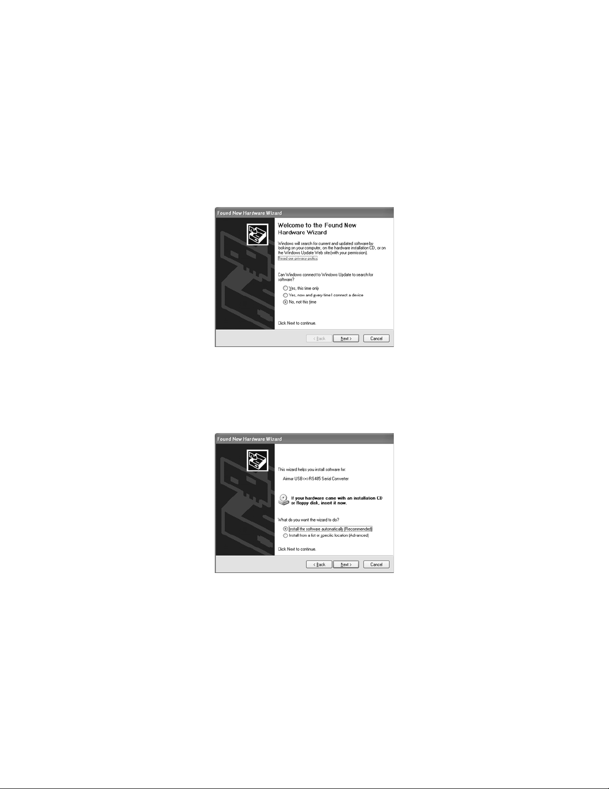
Figure 11. Found New Hardware Wizard window
Figure 12. Found New Hardware Wizard window continued
1. Power the Converter or Combiner.
2. Plug the USB cable into an open USB port on your PC.
3. The Found New Hardware Wizard window will appear (see Figure 11).
Click NO, not this time to allow the driver installation. Click Next to continue.
4. Another Found New Hardware Wizard window will appear (see Figure 12).
Click Install the software automatically. Click Next to continue.
11
Page 12
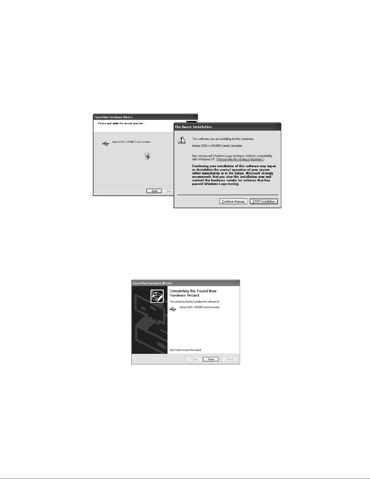
5. The Please Wait window followed by the Hardware Installation caution window
Figure 13. Please Wait window and Hardware Installation Caution window
Figure 14. Completing the Found New Hardware Wizard window
will appear (see Figure 13). The USB Controller Driver is not Microsoft
Windows® certified, however, it has been tested for stable and reliable
operation. Click Continue Anyway to proceed with the installation.
6. When the Language File Replace window appears, click the No To All button.
7. Another Found New Hardware Wizard window will appear (see Figure 14).
Click Finish to install the USB Controller Driver. Then wait for the Found New
Hardware Wizard window to appear again so that the second driver can be
installed.
12
Page 13
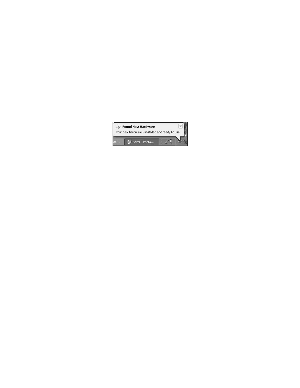
IMPORTANT: The new hardware wizard must run TWICE
Figure 15. “Your new hardware is installed and ready to use” icon
for a complete installation.
Installing the USB Communications Port Driver
1. When the Found New Hardware Wizard window appears again, it will guide you
through the USB Communications Port Driver installation, repeating steps 3 and
6 beginning on page 11. When the installation is complete, some computers will
display the Your new hardware is installed and ready to use icon in the bottom
right of the taskbar (see Figure 15).
2. Close the browser window. Eject the Airmar Sensor Support CD and store it in a
safe place.
NOTE: A new communications port will be assigned:
• If a different Converter/Combiner is connected
• If an existing Converter/Combiner is connected to a different
communications port
The New Hardware Wizard will need to run twice again. The Found New
Hardware Wizard window will appear. Follow the prompts until both the USB
Controller Driver and the USB Communications Port Driver are installed. When
completed, some computers will display the Your new hardware is installed and
ready to use icon in the bottom right of the taskbar (see Figure 15).
13
Page 14
Setting Up WeatherCaster™ Software
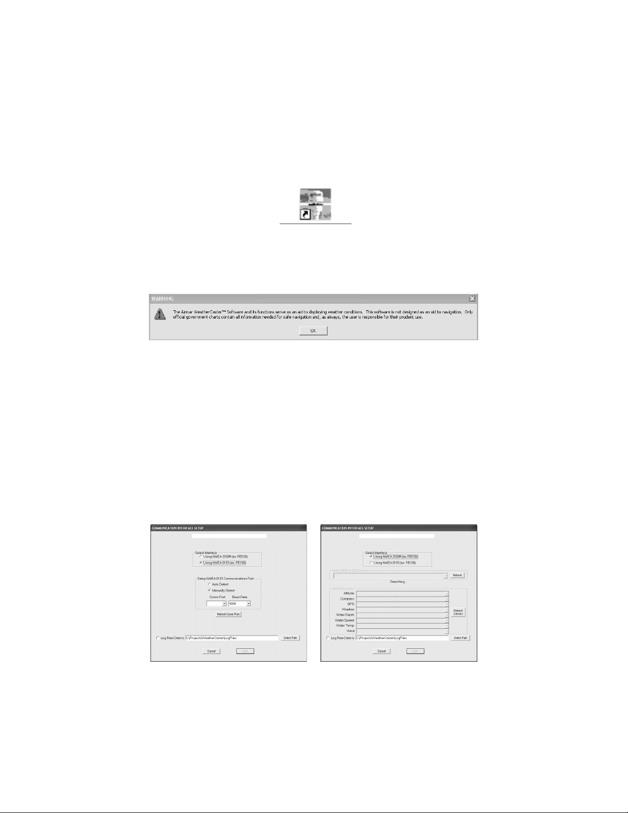
Figure 16. WeatherCaster icon
Figure 17. Warning: Navigation Aid Only window
Figure 18. Sensor Communications Interface Setup window
NMEA 0183 interface
Searching for NMEA 2000
®
Gateway
After the WeatherCaster software is successfully installed, click the WeatherCaster
icon on your PC’s desktop or Start>Program>Airmar>WeatherCaster (see Figure 16).
A window with the following warning will appear (see Figure 17). Click OK to continue.
When the WeatherCaster software starts for the first time, a Communications
Interface Setup window will appear, similar to one of those shown below
(see Figure 18). In the Select Interface dialogue box, chose either an NMEA 0183 or
an NMEA 2000
button to the left of your choice.
NOTE: For the WeatherStation Instrument to communicate with WeatherCaster
software, one of the following devices must be installed.
• NMEA 0183/RS485 to USB Data Converter
• NMEA 0183 Combiner
• NMEA 2000® CAN to USB Gateway
®
interface based upon the communication device installed. Click the
14
Page 15
NMEA 0183 Interface
Figure 19. Identify the communications port
Auto Detect
If Auto Detect is chosen, all available communications ports and baud rates, starting
with the selected port and baud rate, will be checked for a sensor response.
1. Click the Auto Detect button.
2. Click the Refresh Comm. Ports button.
3. Click Apply.
NOTE: The WeatherCaster software may not auto-detect the sensor if more than
one NMEA 0183 device is connected to the computer. You may need to manually
select the communications port.
Manually Select
If Manually Select is chosen, only the selected communications port and baud
rate will be checked for a sensor response.
1. Click the Manually Select button.
2. Click the Refresh Comm. Ports button.
3. Using the drop-down menus, select the communications port that the Converter
or Combiner is connected to and the corresponding baud rate.
• Converter: 4800
• Combiner: 38400
• Combiner purchased before Sept. 9, 2006: 57600
4. Click Apply. When the sensor is detected, the WeatherCaster screen will
appear automatically.
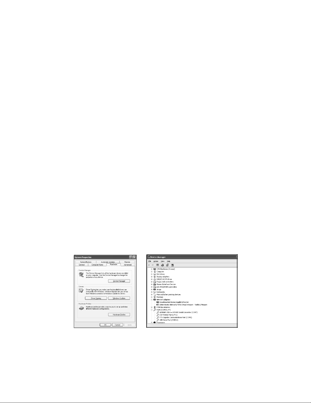
NOTE: If you do not know to which communications port the Converter or
Combiner is connected, click the PC’s Start button or right click My Computer. Go
to Control Panel>System. On some computers, go to Settings>Control
Panel>Printers and Other Hardware, then click System. In the System Properties
window, click the Hardware tab, then click Device Manager (see Figure 19). In the
Device manager window, expand Ports by clicking the “+” button. Identify the
communications port. In the Figure below, it is communications port 7 (com7).
15
Page 16
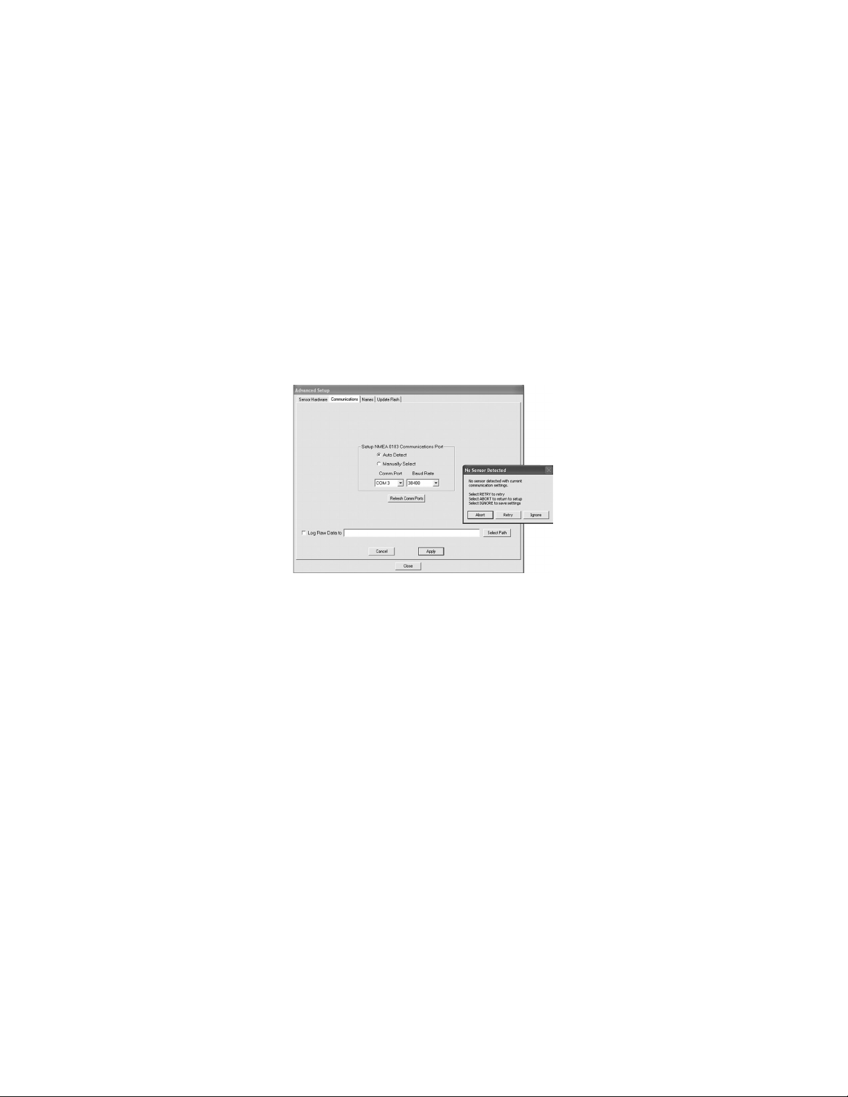
No Sensor Detected
Figure 20. Communications and No Sensor Detected windows
If no sensor is found using the previously selected communication settings, the
Communications Interface Setup window will appear with the message, No
sensor detected with current communication settings. Then the No Sensor
Detected window will ask for a decision (see Figure 20).
Choose Abort, Retry, or Ignore.
• If Abort is selected, none of the previously modified setting will be saved, and
the Communications window will be re-displayed.
• If Retry is selected, another attempt to establish communication will be made.
• If Ignore is selected, the modified settings will be saved even though no
communication has been established. On start-up, the WeatherCaster screen
will appear.
16
Page 17
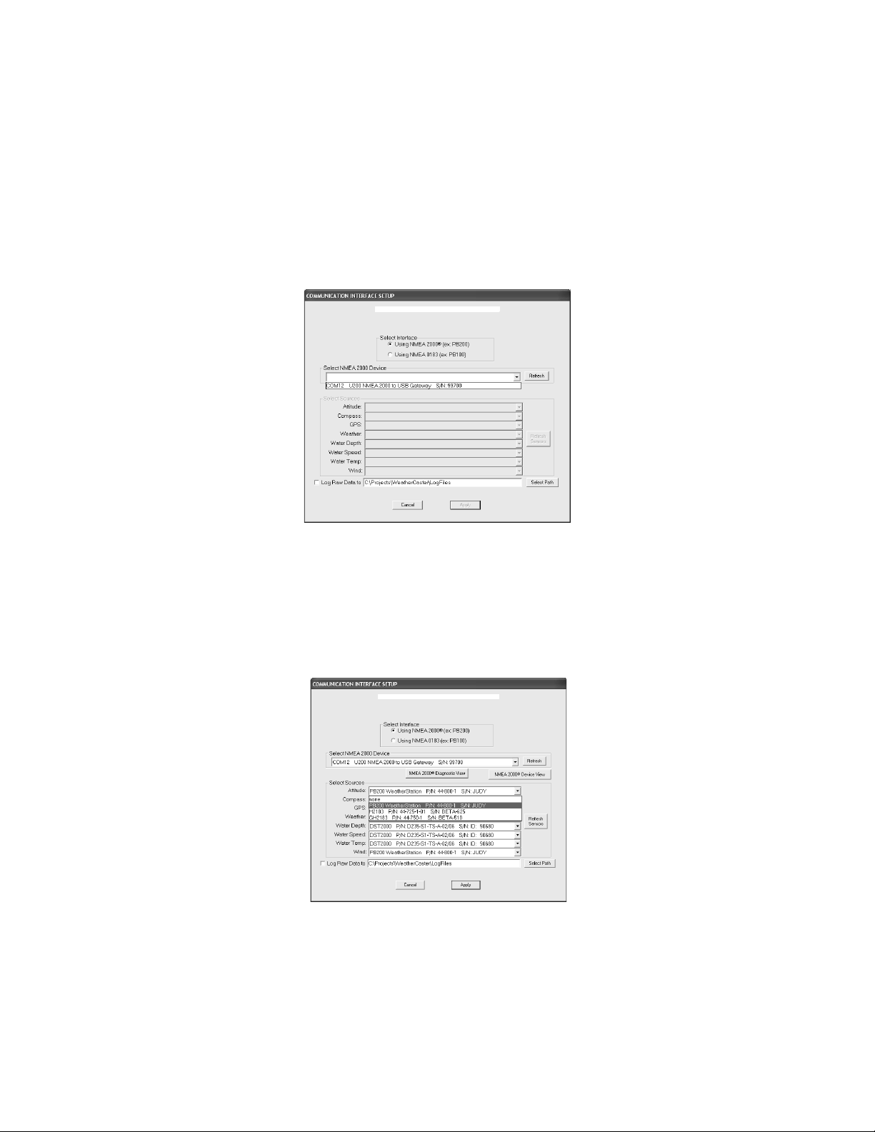
NMEA 2000® Interface
Figure 21. Choose Gateway from drop-down menu
Figure 22. Select a sensor to perform each function
Communications Setup
When the NMEA 2000 Interface is selected, the WeatherCaster software will
search for all recognized NMEA 2000 Gateways. Any located Gateways will be
listed in the drop-down menu (see Figure 21). Select a Gateway. Click Refresh.
The NMEA 2000 connection will search for sensors that can perform any one or
more of the functions recognized by the WeatherCaster software. The functions are
listed in the Select Sources dialogue box (see Figure 22). If more than one sensor
can perform a function, they will be listed on a drop-down menu to the right. Select a
sensor for each function. If no sensor is found or desired, select none.
17
Page 18
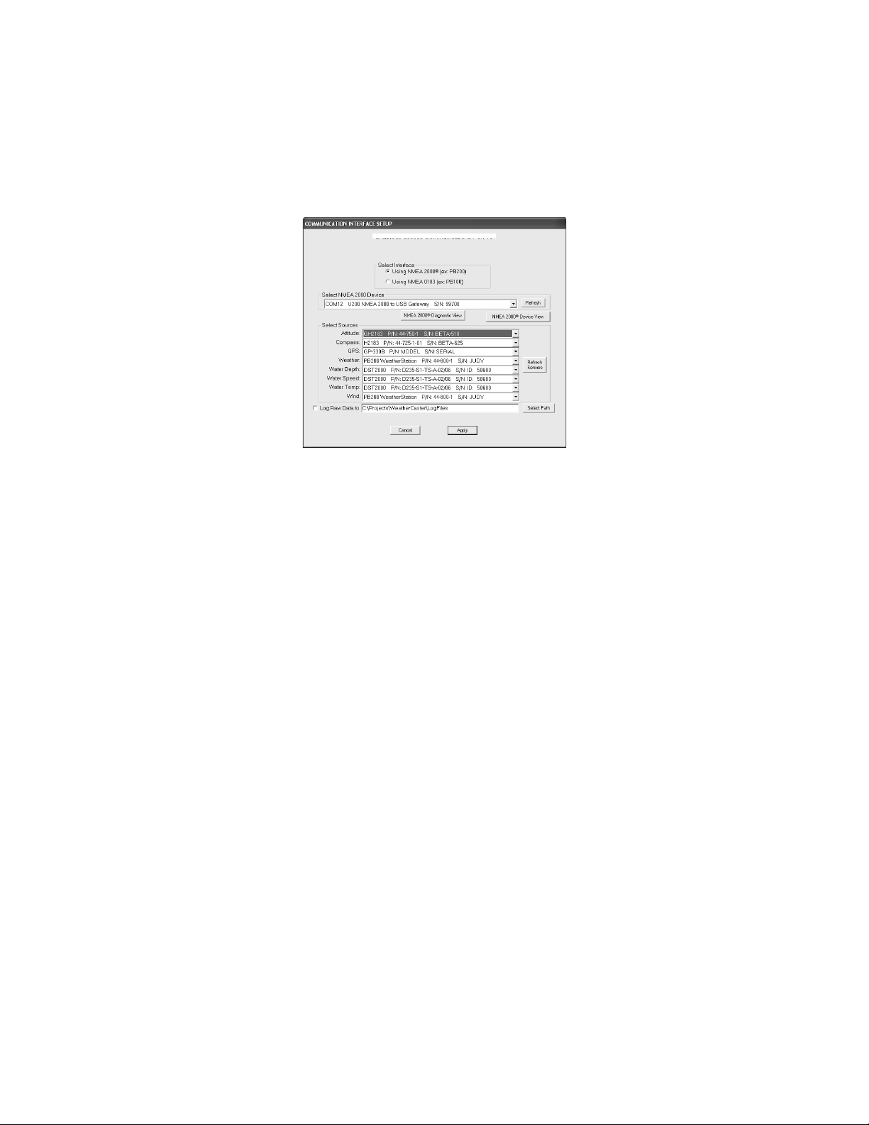
After all the selections have been made, click Apply (see Figure 23).
Figure 23. Apply sensor selections
18
Page 19
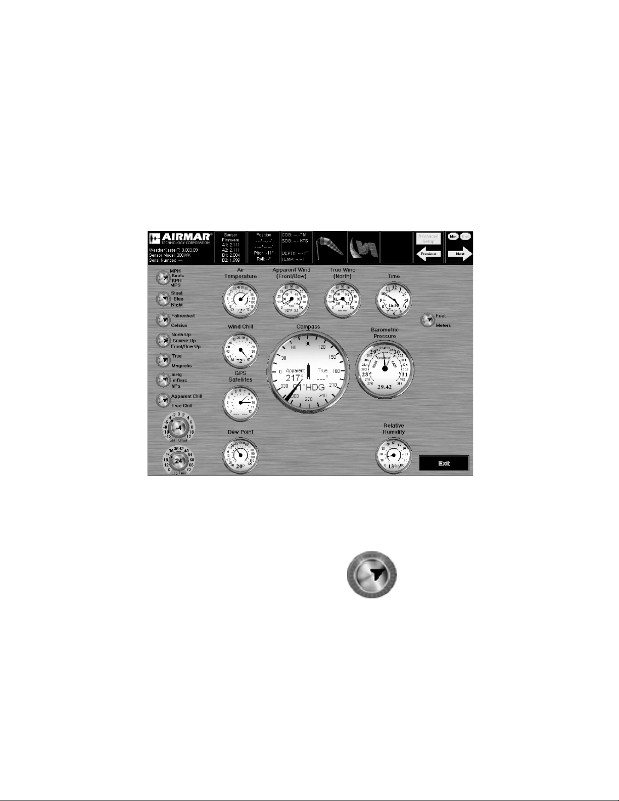
Setup Screen
Figure 24. Setup Screen
SE 10
10 8
MPH
Knots
KPH
MPS
When the WeatherCaster software opens, you will see a Setup screen with
gauges and dials (see Figure 24). The gauges display the data being sent from
the sensor in both analog and digital format. The dials along the left side are
settings that can be changed by the user. This screen is for setting up the display
only.
NOTE: Your screen may look different, depending upon the sensor(s) that is installed
Setting Dials
Wind Speed Setting Dial
This dial allows you to display wind speed in the
following units of measure:
• MPH—Miles Per Hour
• Knots—1 Knot = 1.15 Miles Per Hour
• KPH—Kilometers Per Hour
• MPS—Meters Per Second
To change the setting, click the text to the right
of the dial.
19
Page 20

Background Color Dial
Steel
Blue
Night
Fahrenheit
Celsius
North Up
Course Up
Front/Bow Up
True
Magnetic
This dial allows you to choose the screen
background.
•Steel
•Blue
• Night
To change the setting, click the text to the right
of the dial.
Temperature Setting Dial
This dial allows you to display all of the
temperature readings in the following units of
measure:
• Fahrenheit
• Celsius
To change the setting, click the text to the right
of the dial.
Compass Orientation Dial
This dial allows you to orient the compass
display one of three ways.
• North Up—The traditional orientation in
which north is displayed at the top of the
compass. This orientation will provide true
wind readings relative to North.
• Course Up—The orientation in which the direction of travel is displayed at the
top of the compass. This orientation will provide true wind readings relative to
the course of the vehicle/ vessel.
• Front/Bow Up—The top of the compass will display the direction that the
vehicle/bow is pointing. This orientation will provide wind readings relative to
the front of the vehicle or bow of the boat. The compass will display 0 – 180° on
the left/port side from front to back. And it will display 0 – 180° on the right/
starboard side from front to back. This setting is useful when the vehicle / vessel
is underway, as it helps determine how the wind will affect the direction and
speed.
To change the setting, click the text to the right of the dial.
True or Magnetic North Dial
This dial allows you to set the compass using
either true or magnetic north.
• True North—The direction to the geographic
North Pole
• Magnetic North—The direction to the
magnetic North Pole
To change the setting, click the text to the right
of the dial.
20
Page 21
Barometric Pressure Setting Dial
inHg
mBars
hPa
Apparent Chill
True Chill
Feet
Meters
This dial allows you to display the barometric
pressure in the following units of measure:
• inHg—Inches of Mercury
• mBars—Millibars
• hPa—HectoPascal
To change the setting, click the text to the right
of the dial.
Wind Chill Setting Dial
This dial allows the sensor to calculate the wind
chill temperature based on either apparent or
true wind data.
• Apparent wind
•True wind
To change the setting, click the text to the right
of the dial.
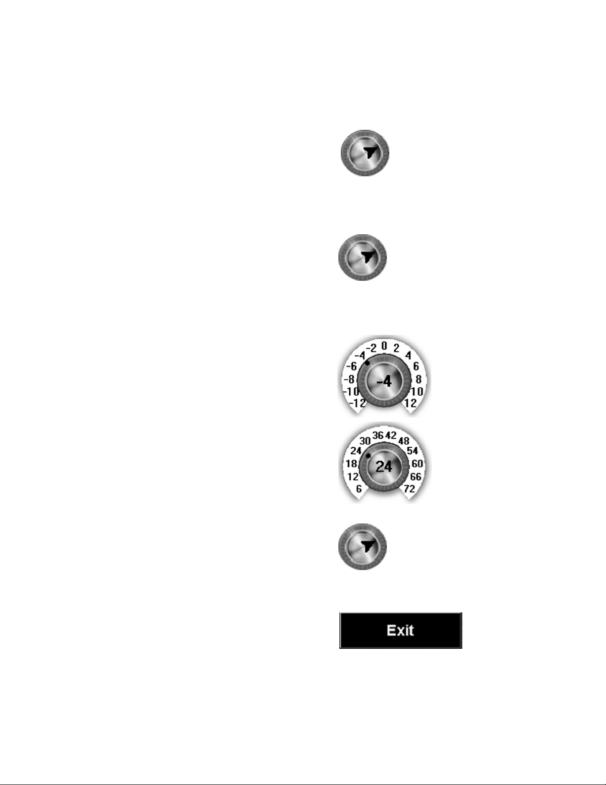
GMT Offset Dial
The Greenwich Mean Time (GMT) Offset Dial
allows you to change the time clock, so it
displays the time in your current location. After
identifying your current Time Zone, change the
setting by clicking on the number that
corresponds to your Time Zone.
Log Time Interval Dial
The sensor saves data for a set period of time,
72 hours. This dial allows you to choose the
length of time that data will be displayed. The
log time can be adjusted in six-hour intervals
from 6 – 72 hours. To change the setting, click
the number that corresponds to the length of
time that you would like data to be displayed.
Water Depth Setting Dial
This dial allows you to display the water depth
reading in the following units of measure:
•Feet
•Meters
To change the setting, click the text to the right
of the dial.
Exit Button
To exit WeatherCaster, click Exit.
21
Page 22

Advanced Setup Button
To change settings in the sensor firmware, click
Advanced Setup.
Previous Arrow
To return to the previous display screen, click
the Previous arrow. (The Weather-Caster
software has three screens.)
Minimize and Exit Buttons
To minimizes the screen, click Min.
Close the WeatherCaster application by clicking
Exit.
Next Arrow
To move to the next display screen, click the
Next arrow. (The WeatherCaster software has
three screens.)
22
Page 23

Using WeatherCaster™ Software
WARNING
Navigation Aid Only—The WeatherCaster™ software is a
means to display weather and navigation data. It is an aid to
navigation only and should never be solely relied upon. It is
not a replacement for traditional navigation aids and
techniques. Only official government charts contain all the
information needed for safe navigation. As always, the enduser is responsible for their prudent use.
The WeatherCaster software has three display screens. To move between
screens, click the Next or the Previous arrow in the top right corner of the screen.
• Setup Screen—This screen contains gauges with dials along the left side. The
dials have settings that can be changed by the user (see Figure 24).
• Analog Gauge Screen—This screen displays the data being sent from the
sensor(s) on gauges in both analog and digital formats (see Figure 25).
• Large Compass and Digital Readout Screen—This screen displays a large
compass on the left and data being sent from the sensor(s) in digital format on
the right (see Figure 26 on page 29).
23
Page 24

Analog Gauge Screen
Figure 25. Analog Gauge Screen
Gauges display the data being sent from the sensor(s) (see Figure 25). Each gauge
displays data in both analog and digital formats.
High and Low Readings
Some gauges display a colored arc. A blue arc shows the lowest reading within a
24 hour period. A red arc show the highest reading within a 24 hour period. White
space between a blue and a red arc shows the range of the readings within a 24
hour period. Blue and red arcs may appear on all gauges except the Pitch and
Roll gauge, the Compass, the Barometric Pressure gauge, and the Time clock.
Displaying Historical Data
You can view historical data for each gauge except the Pitch and Roll gauge, the
Compass, and the Time clock. When you right click on a gauge, a graph will
appear. The graph displays the unit of measure on the left and time at the bottom.
A red line will indicate the history.
24
Page 25

Gauges
Wind Chill
40
20
0
–20
–40
–60
–80
9:00AM 12:00PM
Heat Index
140
120
100
80
60
9:00AM
12:00PM
100
80
60
40
20
0
9:00AM 12:00PM
Air
Temperature
9:00AM 12:00PM
120
100
80
60
40
Apparent Wind
(Front/ Bow)
Wind Chill Gauge
This gauge uses a needle to indicate the
wind chill temperature with a digital readout
at the bottom. Note that Wind Chill
information only appears when the air
temperature is less than 10°C (50° F) and
the wind speed is greater than 2.6Kn
(3MPH). If there is an active humidity
sensor, the Wind Chill gauge will be replace by the Heat Index gauge when the air
temperature is at least 26.7°C (80° F) and the relative humidity is greater than 40%.
To view historical wind chill data, right click the gauge. A graph will appear as
shown. To return to the Wind Chill gauge, right click the graph.
Heat Index Gauge
This gauge uses a needle to indicate the
heat index temperature with a digital
readout at the bottom. Note that Heat
Index data appears only when the air
temperature is at least 26.7°C (80°F) and
the relative humidity is greater than 40%.
To view historical heat index data, right click the gauge. A graph will appear as
shown. To return to the Heat Index gauge, right click the graph.
Air Temperature Gauge
This gauge uses a needle to indicate the air
temperature. There is also a digital readout at
the bottom.
To view historical air temperature data,
right click the gauge. A graph will appear
as shown. To return to the Air Temperature
gauge, right click the graph.
Apparent Wind Gauge
This gauge uses needles to indicate the
apparent wind speed and direction relative
to the front of a vehicle or bow of a boat.
The long needle points to the wind speed,
and the short needle points to the wind
direction. There is also a digital readout at
the bottom.
To view historical apparent wind speed data, right click the gauge. A graph will
appear as shown. To return to the Apparent Wind gauge, right click the graph.
25
Page 26

True Wind Gauge
9:00AM 12:00PM
80
60
40
20
0
True Wind
(North)
Pitch and Roll
Compass
This gauge uses needles to indicate the
true wind speed and direction relative to
north. The long needle points to the wind
speed, and the short needle points to the
wind direction. There is also a digital
readout at the bottom.
To view historical, true wind speed data, right click the gauge. A graph will appear
as shown. To return to the True Wind gauge, right click the graph.
Pitch and Roll Gauge
This gauge uses arrows to indicate pitch and roll. The
average angle of pitch and the average angle of roll is
displayed digitally in degrees.
NOTE: For pitch and roll values to be completely accurate in
a boat, the sensor would need to be installed at the vessel’s
center of gravity—at the waterline. However this is not
recommended because it would interfere with GPS and
weather readings. Remember that the higher the sensor is
above the waterline, the greater the error in the pitch and roll
readouts.
Compass
The Compass displays the true wind direction, the
apparent wind direction, and the heading. No historical
data is collected.
• Apparent wind direction is indicated by a black/white
needle and a black/white digital readout on the left of
the gauge. The port and starboard indicators (P and S)
always appear regardless of the compass orientation.
• True wind direction is indicated by a red/green needle
and a red digital readout on the right of the gauge.
• Heading is displayed as a blue arrow in the center of the gauge and indicates
the direction that the vehicle/vessel is moving. The heading is also digitally
displayed in the lower center in blue.
• Port and Starboard Indicators appear when the Compass is orientated in the
Front/Bow Up mode. A letter “P” representing Port or an “S” representing
Starboard will be displayed to the right of both the true wind direction and the
apparent wind direction digits. The letters reference where the wind is coming
from relative to the front of the vehicle/bow of the vessel.
26
Page 27

Barometric Pressure
9:00AM 12:00PM
Barometric Pressure
30
29.5
29
28.5
28
27.5
30.5
31
31.5
GPS Satellites
9:00AM 12:00PM
6
5
4
3
2
1
0
9:00AM 12:00PM
Dewpoint
80
70
60
50
100
90
This gauge uses a black/white
needle to indicate the current
barometric pressure. A red
needle is the reference marker.
By aligning the red needle with
the black/white needle, it is
possible to see changes in
barometric pressure over time.
A digital readout of the current
barometric pressure is found at the bottom of the gauge.
Left click and hold the mouse over the red reference needle to align it with the
black/white needle. To view historical barometric readings, right click the gauge. A
graph will appear as shown. The red line indicates the barometric pressure over a
period of time. The green dot indicates when the reference needle was set. To
return to the Barometric Pressure gauge, right click the graph.
GPS Satellite Gauge
This gauge uses a long needle to indicate
the number of satellites in view. The short
needle indicates how many satellites are
being used in the calculation to determine
current position. There is also a digital
readout at the bottom. The numeral on the
left indicates the number of satellites in
view. The numeral on the right indicates
the number of satellites used to calculate a fix.
NOTE: Four or more satellites are required for a 3-D fix.
To view historical GPS data, right click the gauge. A graph will appear as shown.
To return to the GPS Satellite gauge, right click the graph.
Dewpoint Gauge
This gauge uses a needle to indicate the
dewpoint temperature. There is also a
digital readout at the bottom.
To view historical dew point data, right
click the gauge. A graph will appear as
shown. To return to the Dewpoint gauge,
right click the graph.
27
Page 28

Relative Humidity Gauge
Relative Humidity
9:00AM 12:00PM
100
80
60
40
20
0
9:00AM 12:00PM
Water Speed
100
80
60
40
20
0
9:00AM 12:00PM
True Wind
(Water)
100
80
60
40
20
0
This gauge uses a needle to indicate the
relative humidity as a percentage. There is
also a digital readout at the bottom.
To view historical humidity data, right click
the gauge. A graph will appear as shown.
To return to the Relative Humidity gauge,
right click the graph.
Water Speed Gauge
This gauge will appear only if you have
installed a sensor measuring speed
through the water, and it is connected
through an optional Combiner. The gauge
uses a needle to indicate speed through
the water. There is also a digital readout at
the bottom.
To view historical water speed data, right click the gauge. A graph will appear as
shown. To return to the Water Speed gauge, right click the graph.
True Wind Speed Relative to Speed
Through Water Gauge
This gauge will appear only if you have
installed a sensor measuring speed
through the water, and the sensor is
connected through an optional Combiner.
True wind speed relative to speed through
water cannot be calculated using GPS
readings.
The gauge uses needles to indicate true wind speed and direction relative to
north, based on speed through water. The long needle points to the wind speed,
and the short needle points to the wind direction. There is also a digital readout at
the bottom.
To view historical data, right click the gauge. A graph will appear as shown. To
return to the True Wind Relative to Water gauge, right click the graph.
28
Page 29

Large Compass & Digital Readout Screen
Figure 26. Large Compass and Digital Readout Screen
To view the Large Compass and Digital Readout Screen, click the Next arrow at
the top right of the display. This screen shows a large compass on the left and
readings in digital format on the right (see Figure 26). This screen does not
display historical data.
Compass
The Compass displays the true wind direction, the apparent wind direction, and
the heading (see Figure 26).
• Apparent wind direction is indicated by a black needle and a black digital
readout on the left of the gauge.
• True wind direction is indicated by a red needle and a red digital readout on
the right of the gauge.
• Heading is displayed as a blue arrow in the center of the gauge and indicates
the direction that the vehicle / vessel is moving. The heading is also digitally
displayed in the lower center in blue.
• Port and starboard Indicators appear when the Compass is orientated in the
Front/Bow Up mode. A letter “P” representing Port or an “S” representing
Starboard will be displayed to the right of both the true wind direction and the
apparent wind direction digits. The letters reference where the wind is coming
from relative to the front of the vehicle/bow of the vessel.
29
Page 30

Digital Readings
The right side of the screen displays some or all of the following readings
depending upon the sensor(s) installed and selected (see Figure 26):
• Apparent wind speed and direction relative to the front / bow
• True wind speed and direction relative to north
• Air temperature
• Wind chill temperature or heat index temperature— The heat index
temperature will appear only if a humidity sensor is present and the air
temperature is at least 26.7°C (80°F) and the relative humidity is greater than
40%.
• Barometric pressure
• Time—Displayed in a 12 and a 24 hour format
• Relative humidity
• Dewpoint
• Water speed—It will appear only if you have installed a sensor measuring
speed through the water, and it is connected through an optional Combiner.
• True wind relative to water—It will appear only if you have installed a sensor
measuring speed through the water, and it is connected to a Combiner.
30
Page 31

Data Boxes
1. 2.
3.
4.
5. 6.
7.
Figure 27. Data boxes
15– 20 knots Small Craft Gale Warning Tropical Storm
Warning
Hurricane
Warning
Warning
Figure 28. Wind-speed icons
There are seven data boxes at the top of each screen (see Figure 27).
1. This box displays the WeatherCaster software version number as well as the
model number and serial number / name of the sensor that is currently being
monitored.
2. This box displays the firmware version that is installed within the sensor itself.
3. This box displays the vehicle/ vessel ‘s current position on the globe in latitude
and longitude as determined using GPS. The average angle of pitch and the
average angle of roll is displayed digitally in degrees.
4. This box displays the vehicle/ vessel ’s speed over ground (SOG) and course
over ground (COG) which is calculated using GPS. If you have an Airmar Smart
Sensor connected through an optional Combiner, it will also display water depth
and water temperature.
5. This box displays the wind-speed icon that relates to the actual wind speed. The
icon will change as the wind speed increases or decreases. A wind sock
indicates a wind speed of 0 to 20 knots, while a flag indicates higher wind
(see Figure 28).
6. This icon indicates if the GPS inside the sensor has a satellite fix. When the
icon is flashing, there is no GPS fix. A stable icon (no flashing) indicates a fix.
• 2D indicates a 2D fix.
• 3D indicates a 3D fix.
• SD indicates the unit has a satellite differential fix, either WAAS or EGNOS.
7. This icon will appear only when the air temperature is below 0° C (32° F).
31
Page 32

Advanced Setup—Firmware Settings
Figure 29. Advanced Setup window
NMEA 0183 interface
NMEA 2000
®
interface
Figure 30. Advanced Setup window—Source Sensor drop-down menu
The firmware resides within the sensor itself and is separate from the
WeatherCaster software. To access these firmware settings, click the Advanced
Setup button found at the top right of each WeatherCaster screen.
There are tabs at the top of the Advanced Setup window (see Figure 29). Click a
tab to access the relevant window. At any time, return to the WeatherCaster
display screen by clicking the Close button.
Sensor Hardware
Information about your sensor and its software is displayed in the box on the left of
the Sensor Hardware screen (see Figure 29).
NMEA 2000 Interface—Since more than one sensor may be connected, you must
choose a source sensor. Select any available sensor from the Source Sensor, dropdown menu. (see Figure 30). Note that a Source Sensor is identified by its function.
If a WeatherStation Instrument is available, it will be the default sensor, and it will be
identified as Weather. The actual sensor associated with each function is defined by
the user through the Communications Interface.
32
Page 33

After a Source Sensor has been selected, its detailed information including the
Figure 31. Advanced Setup window—Source Sensor selected
Figure 32. Self-test Results window
Self-Test Status and results is updated. The data is displayed on the Advanced
Setup window, Sensor Hardware tab (see Figure 31).
NOTE: Any sensor setups such as Sensor Orientation, Sensor Options, and
Restore Factory Defaults are made to the currently selected Source Sensor.
Self-test Status
Your sensor performs a self-test each time the unit is powered ON. Click Details
to check the results of a self-test. A Self-test Results window will appear (see
Figure 32). Click OK to continue.
33
Page 34

Enable/Disable Functionality
Figure 33. NMEA 0183 Display Settings window
You can enable or disable the NMEA 0183 sentence commands or NMEA 2000
PGN commands sent by the sensor and modify the rate of transmission. In the
Advance Setup window on the Sensor Hardware tab, click the Enable/Disable
Functionality button to access the window (see Figure 29). To learn more, go to
either the “NMEA 0183 Interface” section below or the “NMEA 2000 Interface”
section on the following page.
NOTE: The Bandwidth Used cannot exceed 100%. Reduce one or more intervals
until the color is yellow.
• Green Adequate bandwidth
• Yellow Approaching maximum bandwidth (may lose some data)
• Red Maximum bandwidth exceeded
Click Defaults to return to the factory settings. Click Save to accept the changes.
Note that the Save button is enabled only after changes have been made.
NMEA 0183 Interface
You can enable or disable each of the NMEA 0183 sentences sent by the sensor
and specify the number of seconds between the transmission of each sentence.
As you change the interval, the hertz (Hz) transmission rate will also change.
• Display Settings—Not Using WeatherCaster Software
Select the NMEA 0183 Display Settings tab to modify settings when not using
the WeatherCaster software (see Figure 33). These settings will be in effect
whenever the sensor is powered ON.
34
Page 35

• PC Settings—Using WeatherCaster Software
Figure 34. PC Settings window
Figure 35. Advanced Setup window—Source Sensor drop-down menu
In the Enable/Disable Functionality window, click the PC Settings tab to modify
the settings when you are using the sensor with the WeatherCaster software
running (see Figure 34). The settings will remain in effect even after the sensor
is powered OFF and ON again when the WeatherCaster software is running.
NMEA 2000 Interface
You can modify the transmission rate and priority of the NMEA 2000 PGNs for each
selected sensor. In the Advance Setup window on the Sensor Hardware tab, select
a source sensor(s) from the drop-down menu (see Figure 35).
35
Page 36

NOTE: One sensor may report multiple functions. For example, a DST200 may
Figure 36. Advanced Setup window—Source Sensor DST200 identified
PASS
by its Water Speed function only.
Figure 37. Enable/Disable Functionality window
give water depth, water speed, and water temperature data. However, this Source
Sensor will be identified in the drop-down menu by only one of its functions (see
Figure 36).
In the Enable/ Disable Functionality window, you can modify the PGN settings of
any or all of the selected sensors at the same time (see Figure 37) As the interval
changes, the Hz transmission rate will also change.
36
Page 37

If the functionality to report the current PGN setting is not supported, the
Figure 38. Enable/Disable Functionality window—not supported
Figure 39. Sensor Orientation window
WeatherCaster software will not allow the PGN settings to be modified. A window
similar to the one below will be displayed (see Figure 38)
Sensor Orientation
Depending upon the mounting location of the sensor, the azimuth, pitch, and/or
roll settings may need to be changed. Click the Sensor Orientation button to
access the window (see Figure 29). To change a setting, click Change and follow
the screen instructions (see Figure 39). To return all settings to zero, click Zero.
For help in setting the azimuth, pitch, and roll, click Run Assistant. To save
changes, click Save.
37
Page 38

Azimuth Offset
Figure 40. Azimuth Offset window
Figure 41. Pitch Offset window
If the sensor is not installed pointing forward and parallel to the desired centerline /
keel, enter the offset angle in the text box (see Figure 40). (To calculate the
azimuth offset angle, compare the sensor’s compass reading to an independent
compass reading.) To return the setting to zero, click Zero. Click OK to accept the
change.
Pitch Offset
If the sensor is not installed truly vertical relative to the front-back axis, enter the
pitch offset angle in the text box (see Figure 41). (To measure the pitch offset
angle, place an angle finder against the side of the sensor and facing either
forward or backward.) To return the setting to zero, click Zero. Click OK to accept
the change.
38
Page 39

Roll Offset
Figure 42. Roll Offset window
Figure 43. Azimuth Offset window
If the sensor is not installed truly vertical relative to the left-right axis, enter the roll
offset angle in the text box (see Figure 42). (To measure the roll offset angle,
place an angle finder against the side of the sensor and facing either left or right.)
To return the setting to zero, click Zero. Click OK to accept the change.
Run Assistant
For help in setting the azimuth, pitch, and roll offset angles, click Run Assistant in
the Sensor Orientation window (see Figure 39).
The Azimuth Orientation window will open (see Figure 43). If the sensor is not
installed with the alignment tabs or the word “forward” pointing forward and
parallel to the centerline of the vehicle/vessel, enter the offset angle in the text
box. (To calculate the azimuth offset angle, compare the sensor’s compass
reading to an independent compass reading.) To return the setting to zero, click
Zero. Click OK to accept the change and continue.
39
Page 40

The Pitch and Roll Offset window will open (see Figure 44). Follow the screen
Figure 44. Pitch and Roll Offset window
Figure 45. Altitude options window
instructions and the sensor will compensate for the pitch and roll. To return the
setting to zero, click Zero. Click OK to accept the change and continue.
Sensor Options
It is possible to make choices that will affect how the sensor makes some
calculations. In the Advanced Setup window, click the Sensor Options button.
When the window opens, click the tab at the top to access the Altitude, GPS, True
Wind, Damping, Depth, and Temperature options windows (see Figure 29).
Altitude
A fixed altitude setting can be used to calculate a more accurate GPS position
when it is operating in the 2D mode and a more accurate barometric pressure
reading (see Figure 45). In the Fixed Altitude field, enter an altitude relative to sea
level from 0 to 10000.00 to the nearest 0.01 meter.
40
Page 41

• GPS Position Calculations—To calculate a more accurate 2D fix, an altitude
Figure 46. GPS options window
offset can be programed into the sensor. Enter an altitude in the Fixed Altitude
field. Select Use Fixed Altitude Until 3D Fix Acquired.
• MDA Barometric Pressure Options—You can enable correcting for altitude
when the altitude is not available due to the GPS not having a 3D fix. Enter an
altitude in the Fixed Altitude field. Select Use Fixed Altitude When GPS Altitude
Unavailable.
For more information, click Help. To accept the change(s), click Save.
GPS (see Figure 46)
• GPS Options—It is possible to restrict the operation of the GPS to only allow
3D fixes. By selecting Use 3D Fix Only, the sensor will not report a fix until it has
achieved a 3D fix. To re-enable the automatic selection of 2D versus 3D fix
calculations, click the Automatically Select 2D/3D Fixes button.
• WAAS Options—If the internal GPS receiver is WAAS enabled, the WAAS
options will be available. WAAS enabled GPS receivers utilize the Wide Area
Augmentation System to provide more accurate positioning data. Select either
the Disable or Enable Report Fixes As Differential button.
For more information, click Help. To accept the change(s), click Save.
41
Page 42

True Wind
Figure 47. True Wind Options options window
Figure 48. Damping options window
Course-Over-Ground (COG) is used to calculate the True Wind direction and
speed. To disable the use of COG and substitute the internal compass heading in
the calculation, un-click the check box (see Figure 47). For more information, click
Help. To accept the change, click Save.
Damping
Damping is used to control electronic noise for more accurate pitch and roll and
compass. readings. To change a damping coefficient, enter the number in the
appropriate text box (see Figure 48). For more information, click Help. To accept
the change, click Save.
42
Page 43

Depth
Figure 49. Depth options window
Figure 50. Temperature options window
You can modify the depth reading to compensate for the distance between the
transducer’s face and the water surface or a part of the keel (see Figure 49). Enter
a positive value if the transducer’s face is below the waterline. If you want to
measure depth from the bottom of the keel, enter a negative value to compensate
for the distance between the transducer’s face and the bottom of the keel. To
return the setting to zero, click Zero. To accept the change, click Save.
Temperature
You can modify the water temperature reading (see Figure 50). Enter a positive
value to report a temperature higher than what is measured. Enter a negative
value to report a temperature lower than what is measured. To return the setting
to zero, click Zero. To accept the change, click Save.
43
Page 44

Compass Calibration
Figure 51. Compass Calibration Step 1
Figure 52. Step 2
Most Airmar sensors with an internal compass must be calibrated for maximum
accuracy. (Your sensor/instrument owner’s guide will specify if this is required.)
There are two ways to calibrate the compass; auto calibration and commanded
calibration. Commanded calibration uses the WeatherCaster software.
In the Advanced Setup window on the Sensor Hardware tab, select the Source
Sensor (see Figure 29). Click Compass Calibration to begin. The Compass
Calibration window will appear (see Figure 51). Follow Step 1. Click Next to
continue or Cancel to stop.
Follow Step 2 (see Figure 52). Click Next to continue or Cancel to stop.
44
Page 45

If you clicked Next, calibration will begin and the Calibration in Progress window
Figure 53. Calibration in Progress window
Figure 54. Cancel Confirmation window
Figure 55. Cancellation notification window
will appear (see Figure 53).
If you choose to cancel calibration, click Cancel. You will be asked to verify your
selection in the Cancel Confirmation window (see Figure 54).
A Calibration Finished window will notify you of the cancellation (see Figure 55).
45
Page 46

Likewise, if the compass calibration stops due to a calibration error or a time-out
Figure 56. Calibration Finished error window
Figure 57. Calibration successfully completed window
error, a notification window will appear similar to the one shown below (see
Figure 56). To restart the calibration, click Restart.
When the compass calibration is completed successfully, a notification window
will appear (see Figure 57).
46
Page 47

Paddlewheel Calibration/ Water Speed Calibration
Figure 58. Paddlewheel Calibration Step 1
Figure 59. Paddlewheel Calibration Step 2
The paddlewheel can be calibrated if the Water Speed sensor is selected and a
GPS device is available and selected for use. In the Advanced Setup window on
the Sensor Hardware tab, select the Source Sensor, Water Speed (see Figure 36).
On the Communications/Diagnostics tab select a GPS device (see Figure 65).
Return to the Sensor Hardware tab and click Paddlewheel Calibration to begin.
The Paddlewheel Calibration window will appear (see Figure 58). Follow Step 1.
Click Calibrate to adjust the calibration table, Restore to return to the factory
default setting, or Cancel to stop.
Follow Step 2 (see Figure 59). Click Start to begin the process or Cancel to stop.
47
Page 48

If you clicked Start, the Collecting Data window will appear (see Figure 60). Click
Figure 60. Collecting Data window
Figure 61. Calibration Complete window
Cancel to stop.
If the paddlewheel calibration stops due to a calibration error or a time-out error, a
notification window will appear. To restart the calibration, click Restart.
When the calibration has been completed successfully the Calibration Complete
window will appear (see Figure 61).
48
Page 49

If you click Restore, the Confirm Restore window will appear (see Figure 62).
Figure 62. Confirm Restore window
Figure 63. NMEA 2000 Settings window
NMEA 2000® Settings
You can alter the NMEA 2000 settings. In the Advanced Setup window on the
Sensor Hardware tab, click NMEA 2000 Settings to begin (see Figure 29). The
Sensor NMEA 2000 Settings window will appear (see Figure 63).
• Address Claim Parameters lets you set the device instance used in the
address claim name when transmitting the address claim PGN.
• Configuration Information allows you to set modifiable parameters in the
Configuration Information PGN.
49
Page 50

Restore Factory Defaults
Figure 64. Advanced Setup and Confirm Reset windows (NMEA 0183 interface shown)
In the Advanced Setup window, all settings can be returned to the factory defaults
by clicking Restore Factory Defaults (see Figure 64). Before the default settings
are restored, the Confirm Reset window will appear. Click OK to accept the default
settings.
50
Page 51

Communications/Diagnostics
Figure 65. Sensor Communications Interface Setup window
NMEA 0183 interface
Searching for NMEA 2000
®
Gateway
Communication to a sensor can be set-up or modified. In the Advanced Setup
window, click the Communications/Diagnostics tab to access the
Communications window (see Figure 29).
The WeatherCaster software is designed to auto-detect the last known
communications interface setup. If the interface was last set to NMEA 0183, the
WeatherCaster software will attempt to find and connect to a sensor using the
communication port last selected. If the interface was last set to NMEA 2000 protocol,
WeatherCaster software will attempt to find and communicate with the last selected
PC/NMEA 2000 gateway and then to the last selected NMEA 2000 sensors.
If the previous interface is not currently available or it is undetected, a
Communications Interface Setup window will be displayed, similar to one of those
shown below (see Figure 65). In the Select Interface dialogue box, chose either an
NMEA 0183 or an NMEA 2000
choice.
®
interface by clicking the button to the left of your
51
Page 52

NMEA 0183 Interface
Figure 66. Identify the communications port
Auto Detect
If Auto Detect is chosen, all available communications ports and baud rates, starting
with the selected port and baud rate, will be checked for a sensor response.
1. Click the Auto Detect button.
2. Click the Refresh Comm. Ports button.
3. Click Apply.
NOTE: The WeatherCaster software may not auto-detect the sensor if more than
one NMEA 0183 device is connected to the computer. You may need to manually
select the communications port.
Manually Select
If Manually Select is chosen, only the selected communications port and baud
rate will be checked for a sensor response.
1. Click the Manually Select button.
2. Click the Refresh Comm. Ports button.
3. Using the drop-down menus, select the communications port that the Converter
or Combiner is connected to and the corresponding baud rate.
• NMEA 0183 to USB Data Converter: 4800 Baud Rate
• NMEA 0183 to USB Combiner: 38400 Baud Rate
• Combiner purchased before Sept. 9, 2006: 57600 Baud Rate
4. Click Apply. When the sensor is detected, the WeatherCaster screen will
appear automatically.
NOTE: If you do not know to which communications port the Converter or
Combiner is connected, click the PC’s Start button or right click My Computer. Go
to Control Panel>System. On some computers, go to Settings>Control
Panel>Printers and Other Hardware, then click System. In the System Properties
window, click the Hardware tab, then click Device Manager (see Figure 66). In the
Device manager window, expand Ports by clicking the “+” button. Identify the
communications port. In the Figure below, it is communications port 7 (com7).
52
Page 53

No Sensor Detected
Figure 67. Communications and No Sensor Detected windows
If no sensor is found using the previously selected communication settings, the
Communications Interface Setup window will appear with the message, “No
sensor detected with current communication settings.” Then the No Sensor
Detected window will ask for a decision (see Figure 67).
Choose Abort, Retry, or Ignore.
• If Abort is selected, none of the previously modified setting will be saved, and
the Communications window will be redisplayed.
• If Retry is selected, another attempt to establish communication will be made.
• If Ignore is selected, the modified settings will be saved even though no
communication has been established. On start-up, the WeatherCaster screen
will appear.
53
Page 54

NMEA 2000® Interface
Figure 68. NMEA 2000 Device View button on the
Communications Interface Setup window
Figure 69 .NMEA 2000 Device Information window
Communications Setup (see pages 17 - 18)
Device View
You can see detailed information about the Gateway selected. Click NMEA 2000
Device View in the Communications Interface Setup window (see Figure 68).
View information about the Gateway (see Figure 69). To return to the Advanced
Setup window, click Close.
54
Page 55

Raw Data Logging
Raw data logging can also be enabled using the Communications / Diagnostics
window (see Figure 66). When raw data logging is enabled, all data received from
the attached sensor is logged to a data file. The name of the file will be
mmm_dd_yyyy_sn_0183.LOG.
• mmm is the month the data was received
• dd is the day the data was received
• yyyy is the year the data was received
• sn is either the serial number of the sensor (if known) or the port assigned to
the sensor.
A new raw data log file will be created for each new serial number/port and for
each new day. The data within the log file will be in text format.
Click the check box in front of “Log Raw Data to” and select the desired path of the
log files. Then click Apply. To disable raw data logging, uncheck the box to the left
of “Log Raw Data to” and then click Apply.
55
Page 56

Alarms
Figure 70. Alarms window
WeatherCaster software can be used to set alarms for wind speed, water depth,
and barometric pressure. The user can turn alarms ON or OFF as well as define
the value that will cause an alarm to be displayed (see Figure 70).
• Wind Speed Alarm—The Wind Speed Alarm can be set for either apparent or
true wind. If the alarm is ON and the wind speed exceeds the alarm value set,
an alarm message will be displayed.
• Water Depth Alarm—If the Water Depth Alarm is ON and the water depth is
less than the alarm value set, an alarm message will be displayed.
• Barometric Pressure Alarm—If the Barometric Pressure Alarm is ON and the
barometric pressure is less than the alarm value set, an alarm message will be
displayed.
Click the Alarms tab in the Advanced Setup window (see Figure 29). Follow the
screen prompts. To accept each change, click Apply.
56
Page 57

Alarm Notification (see Figure 71)
Figure 71. Alarm Notification window
Figure 72. Alarm Notification window
• If the Acknowledge button is clicked and the reading no longer exceeds the
alarm limit, the Alarm window will close.
• If the Acknowledge button is clicked but the reading continues to exceed the
alarm limit, the alarm window will close, then re-display in 10 seconds.
• To temporarily silence an alarm (snooze), enter the number of minutes the
alarm is to be silenced before it re-displays. Click the Silence button.
• If the user does NOT click the Acknowledge button but the alarm is cleared
either by disabling it on the Alarm tab of the Advanced Setup window or
because the reading no longer exceeds the alarm limit, a notification window
will appear (see Figure 72).
57
Page 58

Names
Figure 73. Sensor designation
Figure 74. Names window
When a sensor is detected by the WeatherCaster software, it is identified by its
serial number. However, a sensor can be given a name. This is useful to easily
identify the origin of data, if more than one sensor will be operating at the same
time. The name or serial number (if no name is assigned) will be displayed in the
upper left corner of the WeatherCaster screen (see Figure 73).
To add, change, or delete names, open the Advanced Setup window and click the
Names tab (see Figure 29). Follow the screen prompts (see Figure 74). To accept
the changes, click Apply.
NOTE: The user is allowed to modify sensor names from any instance of the
WeatherCaster software. The new name for the currently connected sensor will
be automatically displayed. However, if other WeatherCaster instances are
currently running, the new sensor names associated with those instances will not
be automatically viewable. The other sensor name changes will become effective
upon starting a new instance of WeatherCaster for that sensor.
58
Page 59

Storage Identifier
It is possible to identify the origin of historical data that is stored and displayed by
the WeatherCaster software. In the Storage Identifier area of the Names window,
you can choose to store data by sensor serial number, by sensor name, or with no
identifier (see Figure 74). Click the appropriate button and click Apply to accept
the choice.
NOTE: If multiple instances of the WeatherCaster software are running, the
sensor in use must be identified by a serial number or a name.
Deleting a Sensor & Its Stored Historical Information
CAUTION: It is recommended that only sensors that are no longer in service be
deleted.
The Names screen also allows the user to delete all stored information for any
sensor (see Figure 74). Select the desired serial number from the Serial Number
field and click Delete. That sensor and all the data associated with it will be
deleted. However, if another instance of the WeatherCaster software is currently
connected to the sensor being deleted and the sensor is still running, the
WeatherCaster software controlling it will reinitialize that sensor’s information and
begin collecting historical data.
59
Page 60

Update Flash
Updating WeatherStation Firmware
Periodically, Airmar may release updated versions of the WeatherStation’s
firmware that resides within the sensor itself. (This software is separate from the
WeatherCaster software.) The latest version of the firmware with updates and
enhancements will be available for download from Airmar’s website at
www.airmar.com, or a CD can be mailed by Airmar’s technical support personnel.
CAUTION: NMEA 0183
Turn OFF or disconnect all other NMEA 0183 devices from any Airmar Combiner.
Be sure the sensor is the only active device connected to the Combiner.
CAUTION: NMEA 2000
Airmar strongly recommends that you limit the number of NMEA 2000 sensors
powered and communicating on the same NMEA 2000 communication bus.
CAUTION: Be sure the most recent version of the WeatherCaster software is
installed.
CAUTION: Be sure the drivers for any Converter or Combiner are installed.
CAUTION: Be sure there are no applications running on the computer.
CAUTION: Do not interrupt the power while programming is in process. Avoid
using a laptop that is being powered by its battery or a computer with a screen
saver that causes hibernation.
CAUTION: Do not exit the sensor while programing is in process.
NOTE: If you have both a Converter and a Combiner, the flash update will be
faster using the Converter.
1. Download the sensor firmware file.
2. Launch the WeatherCaster software.
3. Click the Advanced Setup button in the upper right corner of the
WeatherCaster display screen.
4. When the Advanced Setup window opens, click the Update Flash tab (see
Figure 29).
60
Page 61

5. Click Select File (see Figure 75). In the Open dialog box, browse to the sensor
Figure 75. Advanced Setup window with Update Flash tab
and Open window
flash file to be used. The file name will end in ”.ax”. Click Open.
6. When the Setup dialog indicates “READY to PROGRAM”, click the PROGRAM
button to perform the flash update. When the flash update has been completed,
there will be two status messages. The window will say “PROGRAMING
COMPLETE” followed by “EEPROM FORMATTING COMPLETE.”
Wait several seconds for the WeatherCaster software to establish
communication with the sensor. When you are finished updating the flash
memory in all sensors, click OK to go to a WeatherCaster display screen.
NOTE: If you are unable to update the flash, select a Baud Rate from the dropdown menu and try again.
61
Page 62

Running Multiple Copies of WeatherCaster Software
Figure 76. WeatherCaster confirmation window
Figure 77. WeatherCaster name/serial number in Windows taskbar
It is possible to run multiple copies of the WeatherCaster software simultaneously
(i.e. multiple instances). You would do this if you want to use more than one
sensor at the same time.
To start the first instance, double click the WeatherCaster icon on your PC’s
desktop or Start>Program>Airmar>WeatherCaster. When the WeatherCaster
screen is displayed, an additional instance of the WeatherCaster software may be
started by double clicking the WeatherCaster icon again. (If necessary, use the
Min button to minimize the current WeatherCaster screen first.) When the
additional instance of the WeatherCaster software is started, a prompt will appear
to verify (see Figure 76). Click Yes.
If it is the first time this additional WeatherCaster instance has been started, the
communications port and baud rate must be setup (see “Communications /
Diagnostics” on page 51).
Although it is possible to run multiple instances of the WeatherCaster software
simultaneously, only one instance will be visible at a time. To view a different
instance, minimize the current WeatherCaster screen by clicking the Min button.
Then select the desired WeatherCaster instance from the Windows Taskbar (see
Figure 77).
62
Page 63

NOTE: It is possible to determine which sensor is being monitored by checking
the serial number/name in the upper left corner of the WeatherCaster screen.
If you close one of the WeatherCaster instances, the next time you double click on
the WeatherCaster icon, the first available instance will be started. For example, if
there are three instances of the WeatherCaster software running simultaneously
and instance B is closed, it may be restarted by simply double clicking the
WeatherCaster icon. However, if both instances A and B are closed, the next time
the WeatherCaster icon is double clicked instance A will be started. It is important
to note that each instance will try to connect to the same communications port that
it used previously. This should provide the connection to the same sensor as
before. However, due to the flexible nature of the system, verify that the desired
sensor is being monitored by checking in the upper left corner of the
WeatherCaster screen.
63
Page 64

Updates & Troubleshooting
WeatherCaster Software Updates
Periodically, Airmar will release updated versions of the WeatherCaster software
and sensor firmware. Updates can be downloaded from Airmar’s web site
www.airmar.com or contact Airmar’s technical support personnel for a CD.
The current version of your firmware is displayed in the second Data Box at the
top of the WeatherCaster software screen (see Figure 73). A1 refers to the
application firmware within the sensor. If your sensor has two microprocessors,
A2 refers to the second firmware application. B1 and B2 refer to the bootloader
firmware. When performing a flash update, only the application firmware will be
uploaded. The bootloader version will not change. To install an updated version of
the sensor firmware, follow the instructions “Update Flash” in the “Advanced
Setup” window.
PC Problems
No Data On Communications Port
If the sensor is connected to a specific communications port but no data is
observed, there are two possible causes. If you updated flash, it may have been
incomplete. Repeat “Update Flash” in the “Advanced Setup” window (see
Figure 29).
It may be necessary to reboot the communications port. This is especially
effective if many different devices have been connected and disconnected from
the PC, thus assigning many different communications ports. Follow the steps
below.
1. From the Start menu, select Control Panel, or right click My Computer.
2. Select the System option.
3. Select the Hardware tab.
4. Select Device Manager.
5. Select Ports.
6. Right click on the Airmar port and select Disable.
7. Wait 10 seconds, then right click on the Airmar port and select Enable.
8. Close all open windows and try to run the WeatherCaster software again.
NOTE: On some computers click Start. Go to Settings>Control Panel>Printers
and Other Hardware, then click System.
Setting the Display Resolution to 1024 X 768 Pixels
When using the WeatherCaster software on a computer with a display resolution
of more than 1024 x 768 pixels (e.g. 800 x 600), the window will be truncated on
the right side and bottom edges. The exit buttons will therefore be hidden from
view. If this happens, you can exit the WeatherCaster software by pressing the
key combination <alt>-F4 (i.e. while pressing and holding the Alt key, press and
release the F4 key). If the display resolution is less than 1024 X 768 pixels (e.g.
1280 x 1024), The WeatherCaster software will not fill the entire PC screen.
64
Page 65

1. From the Start menu, select Control Panel.
Figure 78. Display Properties window
2. Select Display Properties.
3. Select the Settings tab (see Figure 78).
4. Slide the Screen Resolution indicator until 1024 X 768 is selected.
5. Click Apply, then click Yes.
Computer Screen Distortion: DPI Setting
If the computer display’s DPI setting is 120, the WeatherCaster screen will be
distorted. The computer display’s DPI setting must be 96.
1. Right click the desktop and select Properties. the Display Properties dialog box
will appear.
2. Click the Settings tab.
3. Click the Advanced button.
4. In the Plug and Play window, select the General tab.
5. Under DPI setting, choose Normal size (96 DPI) from the drop-down menu.
6. Click OK.
7. If you are prompted to restart the computer, click Yes.
65
Page 66

WeatherCaster Software Problems
Identify the WeatherCaster Version
The WeatherCaster version number is located on the top left corner of each
WeatherCaster screen (see Figure 73). The latest version of the WeatherCaster
software is available for download at www.airmar.com.
Auto-Detecting Communications Ports
If you installed more than one instance of the drivers for the Converter or the
Combiner, the WeatherCaster software may not automatically detect the
appropriate communications port. If upon launching the WeatherCaster software
the Communication Interface Setup window appears with the “No sensor detected
on Port ____ when using baud rate _____,” you will need to manually select the
communications port and the baud rate.
Manually Selecting the Communications Port and Baud Rate
1. Be sure the USB cable is connected to the computer.
2. Follow the instructions in the Advanced Setup section, “Communications”,
“Manually Select.”
Troubleshooting Sensor Data Using Windows HyperTerminal
IMPORTANT: Before starting HyperTerminal, note the number of the
communications port that the sensor is connected to. The Comm. Port number is
found on the Auto-Detecting Sensor Data window when the WeatherCaster
software begins.
IMPORTANT: You must close the WeatherCaster software to use HyperTerminal
with the sensor.
1. From the Start menu, select All Programs>Accessories>Communications>
HyperTerminal.
2. Enter an area code if prompted.
3. Select File>New Connection.
4. Name the connection, then click OK.
5. Select the particular comm. port that the sensor is connected to, then click OK.
66
Page 67

6. Set the bits-per-second to 4800 if connected to a Converter or 38400 if
Figure 79. COM 1 Properties window
connected to a Combiner (see Figure 79). Using the drop-down menus, change
the Data bits to eight, Parity to None, Stop bits to one, and Flow control to
None, as shown below. Click OK.
7. You will see data sentences from the sensor scrolling on the screen, similar to
the example below (see Figure 80). To identify the commands, refer to the
Technical Manual on the Airmar Sensor Support CD. The data can be saved by
going to the File drop-down menu and selecting Save As.
Figure 80. Data Sentences
67
Page 68

Appendix—Technical Information
Baud Rate
The WeatherCaster software needs to be set as follows:
• NMEA 0183 to USB Data Converter: 4800 Baud Rate
• NMEA 0183 to USB Combiner: 38400 Baud Rate
Acronyms and Abbreviations
CD Compact Disk
CD-ROM Compact Disk-Read ONly Memory
COG Course Over Ground
Comm. Port Communications Port
DOP Dilution Of Precision
EGNOS European Geostationary Navigation Overlay Service
GNSS Global Navigation Satellite System
GPS Global Positioning System
Hz Hertz
NMEA National Marine Electronics Association
PC Personal Computer
PGN Parameter Group Number
SD Satellite Differential
SOG Speed Over Ground
USB Universal Serial Bus
WAAS Wide Area Augmentation System
2D Two Dimensional GPS Fix
3D Three dimensional GPS Fix
Glossary
Firmware The software within the sensor hardware
WeatherCaster The PC application program
Contact Us
For on-line technical support visit Airmar’s website. From the home page, click
FAQs.
Website: http://www.airmar.com
Email: info@airmar.com
Tel: 603.673.9570
Fax: 603.673.4624
Trademarks
Adobe® is a registered trademark of Adobe Systems Incorporated.
Airmar® is a registered trademark of Airmar Technology Corporation.
Microsoft® is a registered trademark of Microsoft Corporation.
NMEA 2000® is a registered trademark of the National Marine Electronics Assoc.
Reader® is a registered trademark of Adobe Systems Incorporated.
Smart™ Sensor is a trademark of Airmar Technology Corporation.
WeatherCaster™ is a trademark of Airmar Technology Corporation.
WeatherStation® is a trademark of Airmar Technology Corporation.
Windows® is a registered trademark of Microsoft Corporation.
68
Page 69

35 Meadowbrook Drive, Milford, New Hampshire 03055-4613, USA
www.airmar.com
69
 Loading...