

Page 1
Installation Supplement
REPLACEMENT
TRANSDUCER SUPPORT
FOR BRACKET
Transom Mount, 1kW Transducer models: TM258, TM260, TM265LH, TM265LM, TM270W
Manufactured between October 2011 and February 2012
WARNING
The plastic transducer support may break due to weak plastic.
If a failure occurs while the boat is underway, the transducer may break off and/or fly into the
cockpit, causing property damage, personal injury, and/or death. Remove this bracket and
discard it immediately. Install the replacement bracket supplied.
17-299-03 rev. 01 05/21/12
Tools & Materials
WARNING: Always wear safety goggles and a dust
mask when installing to avoid personal injury.
WARNING: When the boat is placed in the water,
immediately check for leaks around the screws and
any other holes drilled in the hull.
CAUTION: Never pull, carry, or hold the transducer by
the cable as this may sever internal connections.
CAUTION: Do not strike the transducer to release it.
When mounted on the bracket, remove the transducer
by removing the locking pin and hinge pin.
CAUTION: Never use solvents. Cleaners, fuel,
sealants, paint, and other products may contain strong
solvents, such as acetone, which attack many
plastics, greatly reducing their strength.
IMPORTANT: Please read the instructions completely
before proceeding with the installation. These
instructions supersede any other instructions in your
instrument manual if they differ.
Safety goggles
Dust mask
Carpenter’s saw (recommended)
Marine sealant (suitable for below waterline)
Small screwdriver (some installations)
Removing the Old Transducer Support
1. Increase the slack in the cable by removing any cable clamps
and cable cover (see Figure 1). Set the parts aside to reuse.
2. Remove the transducer support from the transducer using the
Allen wrench supplied (see Figure 2). Set the three sockethead-cap screws and washers aside to reuse. Be sure to
temporarily support the weight of the transducer, so it
does not sever the internal connections to the cable.
3. Protect the cable by opening the slot in the cable protector
supplied and pushing it around the cable (see Figure 3). Push the
protector along the cable until it touches the top of the transducer.
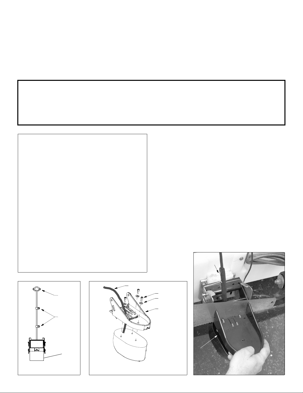
4. Saw completely through the plastic transducer support, being
sure to cut into the hole for the cable. Avoid cutting the
transducer by making the gap between the support and
transducer as
wide as
possible
(see Figure 4).
cable
protector
cable
cover
cable
clamp
Figure 1. Cable clamps, cover
Copyright © 2009 Airmar Technology Corp.
cable
screw (3)
washer (3)
transducer
support
transducer
Figure 2. Detaching transducer
support from transducer
Copyright © 2009 Airmar Technolog y Corp.
gap between
support &
transducer
Figure 3. Sawing transducer support
Page 2
5. Remove the remaining section of the transducer support from
the bracket by remove one safety ring from the end of each pin
(see Figure 5). Remove the pins. Set the two pins, two washers,
and spacer aside to reuse. Discard the cut transducer support.
Installation
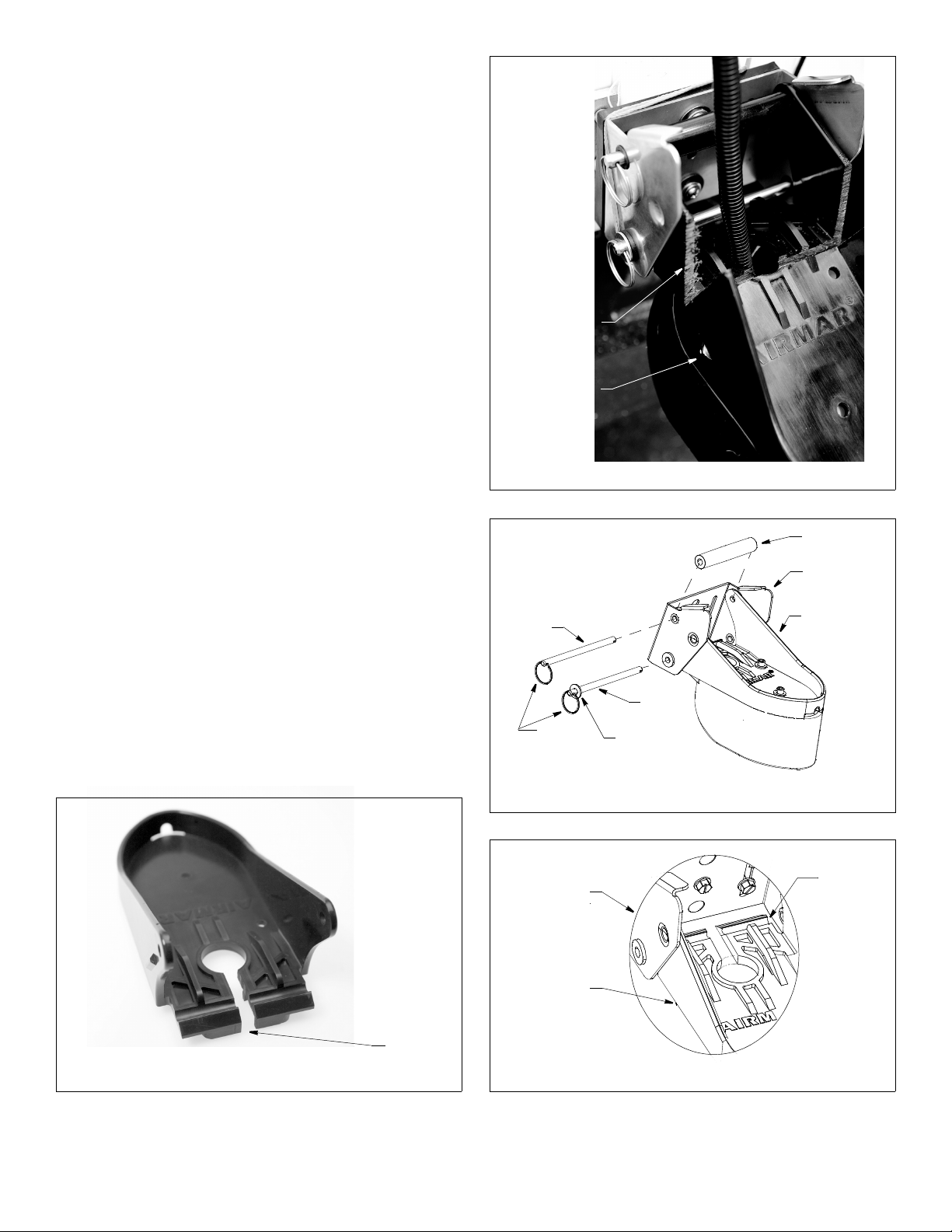
1. The replacement transducer support has a slot that allows it to
slide onto the transducer cable (see Figure 6). Slide the support
into place and align the screw holes with the transducer (see
Figure 2). Fasten the transducer support to the transducer using
the three socket-head-cap screws and washers. Tighten the
screws with the 3/16" Allen wrench supplied.
2. While holding the transducer assembly against the bracket, insert
one of the pins through the upper hole in the bracket and the
transducer support (see Figure 5). Slide the spacer onto the pin
and push it through the remaining hole in the support and the
bracket. Attach a second safety ring to the free end. This pin will
function as a hinge when the transducer is released.
3. Slide a washer onto the remaining pin. Push it through the
lower hole in the bracket, sliding it along the channel in the
transducer support and through the second hole in the bracket
(see Figures 5 and 7). Slide the second washer onto the free
end of the pin and attach the last safety ring. This pin will
function as the locking pin to hold the transducer in the
operational position when the boat is underway.
4. If you have removed the cable cover and/or cable clamps for
easier installation, reattach them (see Figure 1). Apply marine
sealant to the threads of the #6 x 1/2" self-tapping screws to
prevent water from seeping into the transom. If there is a hole
drilled through the transom, apply marine sealant to the space
around the cable where it passes through the transom. Position
the two cable clamps and fasten them in place. If used, push
the cable cover over the cable and screw it in place.
severed
support
gap between
support &
transducer
hinge
pin
Figure 4. Severed transducer support
spacer
bracket
transducer
support
Checking for Leaks
When the boat is placed in the water, immediately check for
leaks around the screws and any other holes drilled in the hull.
Note that very small leaks may not be readily observed. Do not
leave the boat in the water unchecked for more than three hours.
slot for
cable
Figure 6. Replacement transducer support
®
AIRMAR
TECHNOLOGY CORPORATION
2
35 Meadowbrook Drive, Milford, New Hampshire 03055-4613, USA
Copyright © 2012 Airmar Technology Corp. All rights reserved.
locking
safety
ring (4)
Figure 5. Detaching/attaching transducer assembly to bracket
bracket
transducer
support
Figure 7. Detail: Attaching the locking pin
pin
washer (2)
Copyright © 2009 Airmar Technology Corp.
Copyright © 2009 Airmar Technol ogy Corp.
transducer
channel
■ www.airmar.com
 Loading...