

Page 1
INSTALLATION INSTRUCTIONSOWNER’S GUIDE &
Thru-Hull, NMEA 0183
High-Precision Temperature
Model T42
WARNING: Always wear safety goggles and a dust
mask when installing to avoid personal injury.
17-437-01 rev. 03 12/14/10
WARNING: The power must be OFF before wiring if
the instrument is already connected to a power source
to avoid personal injury or death.
WARNING: The power supply voltage must be
12 VDC. Any other voltage may damage the sensor
and/or result in fire, causing damage to the boat,
personal injury, and/ or death.
WARNING: A safe installation requires a 0.5 amp fastblow fuse or circuit breaker. Failure to do so may result
in fire, causing damage to the boat, personal injury,
and/or death.
WARNING: Immediately check for leaks when the
boat is placed in the water. Do not leave the boat
unchecked for more than three hours. Even a small
leak can allow considerable water to accumulate.
CAUTION: Never install a metal sensor on a vessel
with a positive ground system.
CAUTION: Never install a bronze sensor in a metal
hull because electrolytic corrosion will occur.
CAUTION: Never pull, carry, or hold the sensor by its
cable; this may sever internal connections.
CAUTION: Never use solvents. Cleaners, fuel,
sealants, paint, and other products may contain strong
solvents, such as acetone, which attack many
plastics, greatly reducing their strength.
IMPORTANT: Read the instructions completely
before proceeding with the installation. These
instructions supersede any other instructions in your
instrument manual if they differ.
Record the information found on the cable tag for future reference.
Part No._________________Date___________
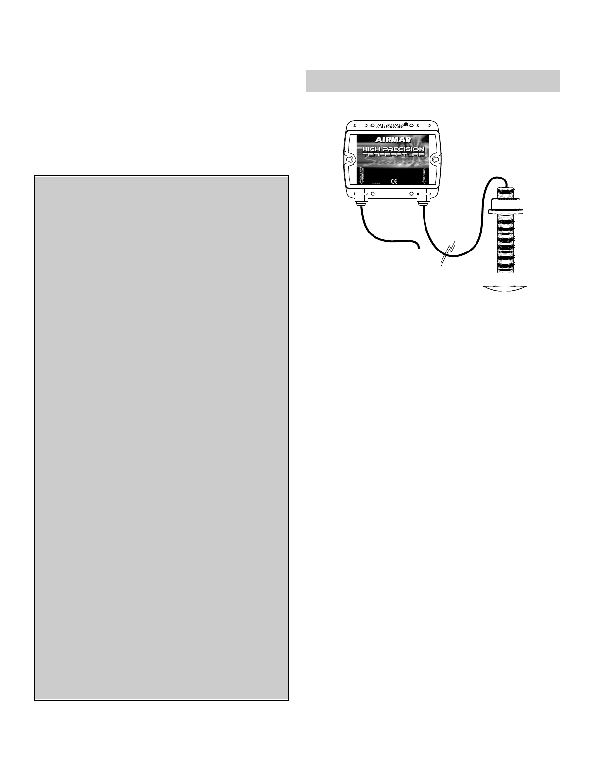
Data
Converter
T42
Applications
• Bronze sensor recommended for fiberglass or wood hull only.
• The hull must be a minimum of 8mm (5/16”) thick at the
mounting location.
Mounting Location
Choose a location where the temperature sensor will be in contact
with the water at all times.
Tools & Materials
Safety goggles
Dust mask
Electric drill
Drill bits: 3mm or 1/8"
21mm or 7/8"
Sandpaper
Mild household detergent or weak solvent (alcohol)
Marine sealant (suitable for below waterline)
Slip-joint pliers
Installation in a cored fiberglass hull (see page 2)
Hole saw for hull interior: 30mm or 1-1/4"
Cylinder, wax, tape, and casting epoxy
Pencil
Grommet(s) (some installations)
Cutting pliers
Wire strippers
Heat-shrink tubing
Heat gun
Phillips screwdriver
Alcohol
Blade screwdrivers
Water-based anti-fouling paint (mandatory in salt water)
Page 2
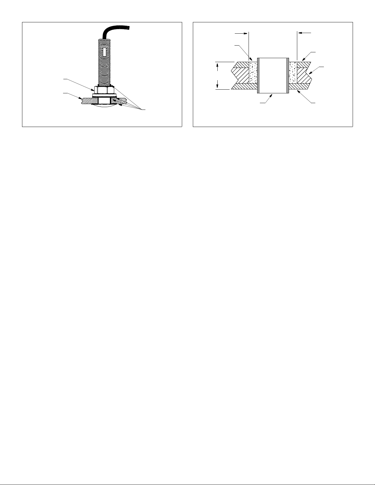
hull nut
hull
Figure 1. Bedding and installing
Copyright © 2005 - 2010 Airmar Technol ogy Corp. Copyright © 2005 Airmar Technology Corp.
bedding
9- 12 mm
pour in
casting
epoxy
hull thickness
(3/8-1/2")
larger than the
hole through the
hull’s outer skin
Figure 2. Preparing a cored fiberglass hull
inner skin
core
outer skinsolid or hollow cylinder
Sensor Installation
Hole Drilling
Cored fiberglass hull—Follow separate instructions on page 2.
1. Drill a 3mm or 1/8" pilot hole from inside the hull. If there is a rib,
strut, or other hull irregularity near the selected mounting
location, drill from the outside.
2. Using the 21mm or 7/8” drill bit, cut a hole perpendicular to the
hull from outside the boat.
3. Sand and clean the area around the hole, inside and outside, to
ensure that the marine sealant will adhere properly to the hull. If
there is any petroleum residue inside the hull, remove it with
either mild household detergent or a weak solvent (alcohol)
before sanding.
Bedding
CAUTION: Be sure all surfaces to be bedded are clean and dry.
1. Remove the hull nut (see Figure 1).
2. Apply a 2 mm (1/16") thick layer of marine sealant around the
flange of the sensor that will contact the hull and up the stem.
The sealant must extend 6mm (1/4") higher than the combined
thickness of the hull and the hull nut. This will ensure that there
is marine sealant in the threads to seal the hull and hold the hull
nut securely in place.
3. Apply a 2 mm (1/16") thick layer of marine sealant to the flange
of the hull nut that will contact the hull.
Installing
1. From outside the hull, thread the cable through the mounting
hole.
2. Push the sensor into the mounting hole using a twisting motion
to squeeze out excess marine sealant (see Figure 1).
3. From inside the hull, slide the hull nut onto the cable. Screw the
hull nut in place. Tighten it with slip-joint pliers.
Cored fiberglass hull—Do not over tighten, crushing the hull.
Wood hull—Allow for the wood to swell before tightening.
4. Remove any excess marine sealant on the outside of the hull to
ensure smooth water flow over the sensor.
Checking for Leaks
When the boat is placed in the water, immediately check around
the thru-hull sensor for leaks. Note that very small leaks may not
be readily observed. Do not to leave the boat in the water for more
than 3 hours before checking it again. If there is a small leak,
there may be considerable bilge water accumulation after 24
hours. If a leak is observed, repeat “Bedding” and “Installing”
immediately (see page 2).
Installation in a Cored Fiberglass Hull
The core (wood or foam) must be cut and sealed carefully. The
core must be protected from water seepage, and the hull must be
reinforced to prevent it from crushing under the hull nut allowing
the sensor to become loose.
CAUTION: Completely seal the hull to prevent water seepage into
the core.
1. Drill a 3mm or 1/8" pilot hole from inside the hull. If there is a rib,
strut, or other hull irregularity near the selected mounting
location, drill from the outside. (If the hole is drilled in the wrong
location, drill a second hole in a better location. Apply masking
tape to the outside of the hull over the incorrect hole and fill it
with epoxy.)
2. Using the 21mm or 7/8" drill bit, cut a hole from outside the hull
through the outer skin only (see Figure 2).
3. From inside the hull using the 30mm or 1-1/4" hole saw, cut
through the inner skin and most of the core. The core material
can be very soft. Apply only light pressure to the hole saw after
cutting through the inner skin to avoid accidentally cutting the
outer skin.
4. Remove the plug of core material so the inside of the outer skin
and the inner core of the hull is fully exposed. Clean and sand
the inner skin, core, and the outer skin around the hole.
5. Coat a hollow or solid cylinder of the correct diameter with wax
and tape it in place. Fill the gap between the cylinder and hull
with casting epoxy. After the epoxy has set, remove the
cylinder.
6. Sand and clean the area around the hole, inside and outside, to
ensure that the sealant will adhere properly to the hull. If there is
any petroleum residue inside the hull, remove it with either mild
household detergent or a weak solvent (alcohol) before sanding.
7. Proceed with “Bedding” and “Installing” (see page 2).
2
Page 3

Connecting
Guidelines
CAUTION: To reduce electrical interference from other electrical
wiring and any on-board equipment with strong magnetic fields such
as radar equipment, radio transmitters, boat engines, generators,
etc., separate the cables by at least 1m (3').
cable
jacket
remove some
insulation from
twisted pairs
to expose
colored wires
colored wires:
blue
white
red
black
remove
10mm (3/8")
of insulation
from colored
wires
CAUTION: Be careful not to tear the cable jackets when passing
them through the bulkhead(s) and other parts of the boat. Use
grommet(s) to prevent chafing.
CAUTION: Make power connections to a 12 VDC power source
that is isolated from the engine start battery(s). Voltage drops may
cause the instrument/receiver/ sensor to lose information and / or
change operating mode.
CAUTION: Use a multimeter to check the polarity and the
connections to the power supply before applying power to the
sensor.
Locating the Data Converter & Routing the Cables
1. Select a convenient dry mounting location for the water-resistant
Data Converter. Locate it a minimum of 1m (3') away from the
display (see Figure 3). Position the converter so the bushings
are easily accessible. If the Data Converter will be mounted on
a vertical surface, be sure the bushings are facing downward to
avoid water seeping into the box.
2. Hold the Data Converter at the selected location and mark the
holes for the screws. Do not fasten it in place at this time.
3. Route the sensor cable from the temperature sensor to the
Data Converter. Do not fasten the cable in place at this time.
4. Route the Data Converter cable from the Data Converter to the
instrument (and power source on some installations).
Do not fasten the cable in place at this time.
heat-shrink
tubing
Figure 4. Preparing the cut end of the Data Converter cable
cut off
bare wire
Copyright © 2005 Airmar Technolog y Corp.
Wiring the Instrument & Power Source
Some installations will connect to the power source within the
instrument. Other installations require wiring to a separate power
source located near the instrument.
1. If the instrument is connected to a power source, be sure the
power is OFF before proceeding.
2. Allowing an extra 25 cm (10") for wiring ease, cut the instrument
cable to length.
3. If the power source is separate from the instrument, strip the
cable jacket and expose the two twisted pairs of wires (see
Figure 4). Strip the outer insulation from each pair.
4. Strip 10mm (3/8") of insulation from each of the four colored
wires making up the pairs.
5. Cut off the bare wire flush with the cable jacket.
6. Protect the cable’s foil shielding from causing a short by using
heat-shrink tubing around the jacket where the wires emerge
from the cable. Be sure the tubing overlaps the wires a
minimum of 6mm (1/4").
7. Connect the wires to the instrument following the instructions in
your owner’s manual (see Figure 3). Use the color code below:
Data Converter
twisted pair:
white NMEA +A
instrument
power
source
blue NMEA –B
instrument
cable
twisted pair:
red 12 VDC +
black 12 VDC –/ground
sensor
cable
Figure 3. Connecting to the instrument
and a separate power source (some installations) (not to scale)
Copyright © 2007 Airmar Technol ogy Corp.
White NMEA + A
Blue NMEA – B
8. Connect to the power supply. It will either be within the
instrument or a separate power source. Use the color code
below:
Red 12 VDC +
Black 12 VDC –/ground
3
Page 4

Connecting the Sensor to the Data Converter
If your sensor came with a connector, plug it into the Data
Converter. If your sensor does not have a connector, follow the
instructions below.
1. Allowing an extra 25 cm (10") for wiring ease, cut the sensor
cable to length.
2. Remove the cover of the Data Converter. Peel the tape away
from the inside and set the screws aside.
3. Push approximately 200mm (8") of the sensor cable through
the bushing of the Data Converter (see Figure 5). To ease
sliding, apply alcohol to the cable jacket.
4. Strip 60mm (2-1/2") of the outer jacket and foil shielding from
the cut end.
5. Strip 10mm (3/8") of conductor insulation from the end of each
colored wire.
Data Converter
terminal
4
8
bushings
function
temp +
temp –
1
2
3
4
5
6
7
8
wire color
blue
black
sensor
cable
6. Cut off the bare wire flush with the cable jacket.
7. Protect the cable’s foil shielding from causing a short by using
heat-shrink tubing around the jacket where the wires emerge
from the cable. The tubing must overlap the wires a minimum of
6mm (1/4").
8. From outside the Data Converter, carefully pull the sensor cable
until only 13mm (1/2") of the cable jacket remains inside the box.
9. Connect each colored wire in turn to its corresponding terminal
on the terminal block (see Figure 5). Following the color code
listed on the inside of the Data Converter cover, insert the
stripped end of the wire into the hole in the terminal and tighten
the screw using a small blade screwdriver. Be sure the stripped
end of the wire is inserted up to its insulation only. Do not
include any insulation inside the terminal. Gently tug on the wire
to ensure that it is securely fastened. Repeat this process until
all the wires are connected.
10.Arrange the wires neatly inside the Data Converter, being sure
that no bare wires are touching.
11.Hand tighten the nut on the bushing to make a water-resistant
seal.
12.Reattach the Data Converter cover with the screws supplied.
Completing the Installation
1. Using a 3mm or 1/8" drill bit, drill the holes for the screws at the
selected Data Converter mounting location.
2. Fasten the Data Converter using the four screws supplied.
3. Fasten all the cables in place.
Figure 5. Connecting the sensor to the Data Converter
(some installations)
Copyright © 2007 Airmar Technology Cor p.
Maintenance & Replacement
Aquatic growth can accumulate rapidly on the sensor’s surface
reducing its performance within weeks. Clean the surface with a
Scotch-Brite® scour pad and mild household detergent taking
care to avoid making scratches. If the fouling is severe, lightly wet
sand with fine grade wet / dry paper.
Anti-fouling Paint
Surfaces exposed to salt water must be coated with anti-fouling
paint. Use water-based anti-fouling paint only. Never use ketonebased paint since ketones can attack many plastics possibly
damaging the sensor. Reapply anti-fouling paint every 6 months
or at the beginning of each boating season.
Replacement Sensor & Parts
The information needed to order a replacement sensor is printed
on the cable tag. Do not remove this tag. When ordering, specify
the part number and date. For convenient reference, record this
information at the top of page one.
Lost, broken, or worn parts should be replaced immediately.
Hull nut 02-031-3
Obtain parts from your instrument manufacturer or marine dealer.
Gemeco Tel: 803-693-0777
(USA) Fax: 803-693-0477
email: sales@gemeco.com
Airmar EMEA Tel: +33.(0)2.23.52.06.48
(Europe, Middle East, Africa) Fax: +33.(0)2.23.52.06.49
email: sales@airmar-emea.com
®
AIRMAR
TECHNOLOGY CORPORATION
4
35 Meadowbrook Drive, Milford, New Hampshire 03055-4613, USA
www.airmar.com
Copyright © 2005 - 2010 Airmar Technology Corp. All rights reserved.
 Loading...