

Page 1
Switchbox with Remote Switch
Models: SB260, SB264
WARNING: Always wear safety goggles and a dust
mask when installing to prevent personal injury.
WARNING: The power must be “OFF” before
proceeding with the installation.
17-498-01 rev.02 12/14/10
WARNING: A safe installation requires a 0.5 amp fastblow fuse or circuit breaker. Failure to do so may
damage the product and /or result in fire, damage to
the boat, and/or personal injury.
CAUTION: To reduce electrical interference from
other electrical wiring and any on-board equipment with
strong magnetic fields such as radar equipment, radio
transmitters, boat engines, generators, etc., separate
the cables by at least 1m (3').
CAUTION: Be careful not to tear the cable jackets
when passing them through bulkheads and other
parts of the boat. Use grommets to prevent chaffing.
Use deck glands to prevent water seepage into the
boat.
CAUTION: Use a multimeter to check the polarity and
the connections to the 10 - 32 VDC power supply
before applying power to the transducer(s).
IMPORTANT: Please read the instructions completely
before proceeding with the installation. These
instructions supersede any other instructions in your
instrument manual if they differ.
INSTALLATION INSTRUCTIONSOWNER’S GUIDE &
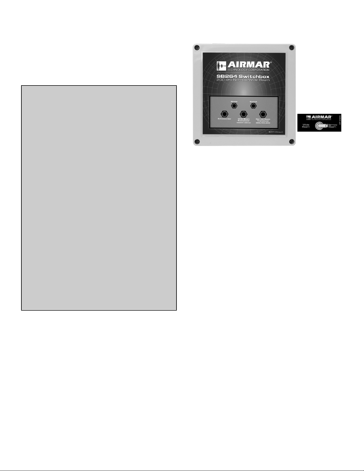
Figure 1. SB264 Switchbox and remote switch
Tools & Materials
Safety glasses
Dust mask
Grommets (some installations)
Deck glands (some installations)
Cutting pliers
Phillips screwdrivers
Pencil
Electric drill
Drill bits:
Switchbox 3mm or 1/8"
Remote switch 11mm or 1/2" spade bit
Sandpaper
Weak solvent (such as alcohol)
Wire strippers
Heat shrink tubing
Blade screwdriver
Pliers
Adjustable wrench
Cable ties (some installations)
Copyright © 2008 Airmar Technolog y Corp.
Applications
• Single transmission line transducers and echosounders only
• 1kW echosounders only. Do not use with 2 kW echosounders.
• SB260 switches between:
- Two depth transducers connected to one echosounder. The
transducers must use C32 or C332 cable.
- Two echosounders connected to one depth transducer. The
echosounder must be dual-frequency with a single
transmission-line. The transducer must use C32 or C332
cable.
• SB264
Switches between a wide-beam and a narrow-beam depth
transducer connected to one echosounder. Pair a wide-beam
SS264W with one of the narrow-beam models such as: B258,
B260, or M260. Both transducers must have C32 or C332
cable.
Locating Switchbox, Remote Switch & Cables
IMPORTANT: Be sure to allow an extra 25 cm (10") of cable to
make the connections within the switchbox.
Switchbox—Select a convenient dry mounting location for the
water-resistant switchbox about 1–2m (3' – 5') from the echosounder(s).
• Retrofit—If the transducer(s) and echosounder(s) are already
installed, select a location with easy access to the cable(s). Be
sure the cable(s) will be long enough to make the necessary
connections. Allow an extra 25 cm (10") for wiring ease.
• New installation—Install the transducer(s) and echosounder(s)
before connecting the switchbox. Plan the cable runs.
Remote Switch—Locate the remote switch on the dash panel or
other convenient location near the echosounder. Check the backside for any obstructions such as cables and wires.
• Minimum clearance on backside 36mm (1-1/2")
• Maximum panel thickness6mm (1/4”)
Page 2
Running the Cables
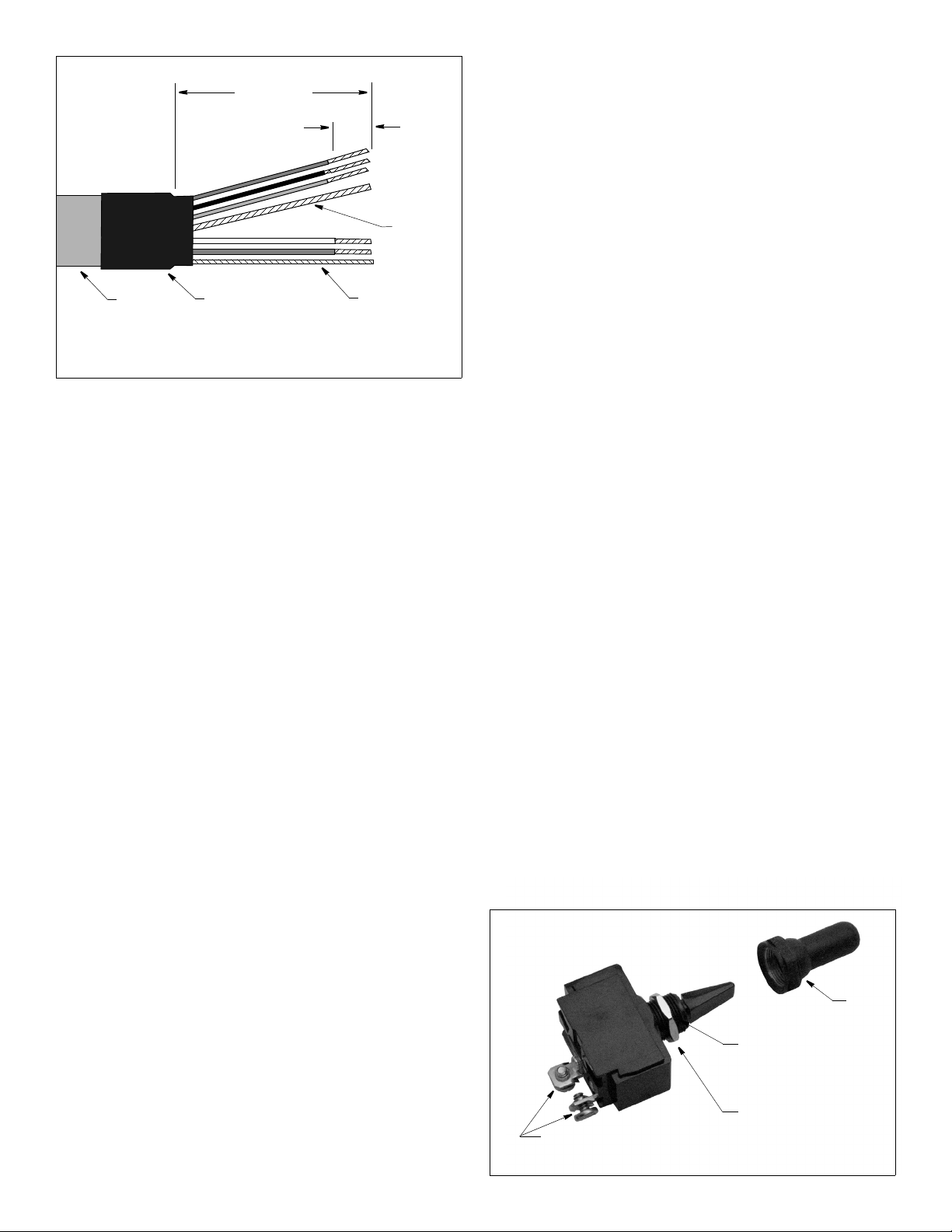
Figure 2. Preparing the cable (SS264W cable shown)
64mm (2 1/2")
remove cable jacket and
10mm
(3/8")
cable
jacket
inner bare
(depth)
outer bare
(shield)
remove
insulation
foil shielding
heat-shrink
tubing
Copyright © 2008 Airmar Technolog y Corp.
If new equipment is being installed, route the transducer cable(s),
the echosounder cable(s), the power cable, and the remote switch
cable to the proposed location of the switchbox before beginning
the installation.
• To reduce electrical interference from other electrical wiring
and any on-board equipment with strong magnetic fields such
as radar equipment, radio transmitters, boat engines,
generators, etc., separate the cables by at least 1m (3').
• Use grommets when passing cables through bulkheads and
other parts of the boat to prevent chafing.
• Use deck glands where necessary to prevent water seepage
into the boat.
• Allow an extra 25 cm (10") of cable for wiring ease.
• Do not fasten the cables in place at this time.
Hole Drilling
1. Remove the switchbox cover and set aside along with the four
screws. Hold the switchbox at the selected location and mark the
position of the screw holes.
NOTE: If the switchbox will be mounted on a vertical surface,
face the compression fittings downward to avoid any possibility
of water seeping into the box.
Installing the Remote Switch
IMPORTANT: It may be easier to wire the remote switch before
installing it in the mounting surface.
1. Strip 60mm (2-1/2") of the cable jacket and foil shielding from
one end of the C2 cable (see Figure 2).
2. Strip 10mm (3/8") of conductor insulation from the end of each
insulated wire in each cable.
3. Protect the cable’s foil shielding from causing a short by using
heat shrink tubing around the jacket where the wires emerge
from the cable. The tubing must overlap the wires a minimum of
6mm (1/4").
4. On the switch, unscrew the plastic ring and discard. It will not be
used. Unscrew the hexagonal nut and set aside.
5. Connect the blue wire to one of the screw terminals on the back
of the remote switch and the black wire to the other terminal
(see Figure 3). Either wire can be connected to either screw
terminal. It will not affect the performance of the switch.
Connect each wire by loosening a screw. Wrap the striped end
of the wire around the threads of the screw and tighten it again.
6. From the backside of the mounting surface, push the toggle
through the mounting hole. With the notch on the threaded stem
facing the word “Wide-Beam” or “A” on the label, screw the nut
against the surface. Tighten it with an adjustable wrench.
7. Screw the water-resistant boot onto the toggle switch.
Preparing the Cables
1. Allowing an extra 25 cm (10") for wiring ease, cut each cable to
length. Do not fasten the cables in place at this time.
2. Push approximately 200mm (8") of each cable through the
appropriate compression fitting. Follow the diagram on the
switchbox cover (see Figure 1). Be careful not to damage the
circuit board.
3. Strip 60mm (2-1/2") of the cable jacket and foil shielding from
the cut end of each cable (see Figure 2).
4. Strip 10mm (3/8") of conductor insulation from the end of each
colored wire in each cable.
5. Protect each cable’s foil shielding from causing a short inside
the switchbox by using heat shrink tubing around the jacket
where the wires emerge from the cable. The tubing must
overlap the wires a minimum of 6mm (1/4").
2. At the marked locations, drill 3mm or 1/8" holes to a depth of
10mm (3/8"). Do not fasten the switchbox in place at this time.
3. At the planned location for the switch, use the label as a
template to mark the hole (see Figure 1).
4. Drill a 3mm or 1/8" pilot hole. Using a 11mm or 1/2" drill bit, drill
the hole for the switch.
5. Sand the area around the hole, inside and out. Clean the
surface with a weak solvent such as alcohol to ensure the label
will adhere properly.
6. Apply the switch label by removing the backing from the
adhesive and pressing the label firmly into place.
2
screw terminals
Figure 3. Installing the switch
boot
notch
faces word
“widebeam”
or “A” on label
hexagonal nut
Copyright © 2008 Airmar Technol ogy Corp.
Page 3

terminal (25)
A
A or
B
B or
compression
fitting
power
supply
Figure 4. Connecting the switchbox
Copyright © 2008 Airmar Technolog y Corp.
Connecting the Switchbox
CAUTION: Be sure to connect each wire to the correct terminal in
the correct terminal block.
Wire each cable to its corresponding terminal block (see Figure 4).
Follow the color code on the PC board. Insert the stripped end of
each colored wire into the square hole in the correspondingly
labeled terminal. Using a small Phillips screwdriver, tighten the
terminal screw to lock the wire into place. Be sure the stripped
end of the wire is inserted up to the insulation only. Do not include
any insulation inside the terminal. Gently tug on the wire to ensure
it is firmly held in place. Repeat this process until all the wires are
connected.
NOTE: Some echosounder cables contain wire colors that differ
from those listed on the PC board. And some cables do not
contain all the wire colors listed on the PC board. If a wire color
(not to scale)
differs, match the wire’s function to the function listed on the PC
board. Check the table on page 4.
NOTE: It may be easiest to connect the cables in the following
order:
• SB264
Echosounder
Wide-beam transducer SS264W
Narrow-beam transducer A: B256, B258, B260, or M260
Power
Remote switch
• SB260
Echosounder or transducer
Transducer B or Echosounder B
Transducer A or Echosounder A
Power
Remote switch
3
Page 4

Echosounder
Brand
Furuno brown white T-
Lowrance no orange wire orange not used
Navman/
Northstar
Raymarine green follow instructions below rsense
Wire Color Terminal label Wire Function
white brown T+
no orange wire orange not used
Raymarine Echosounder Only
If you are connecting a Raymarine echosounder(s), the cable
contains a green wire. Since there is no terminal on the PC board
labelled green, you will need to use the supplies in the plastic bag
marked Raymarine to connect the green wire. If you are connecting two echosounders, follow the steps below with both cables.
1. Strip an additional 10mm (3/8") of insulation from the brown wire.
2. Connect the green wire and one resistor by inserting the end of
each into separate holes in the butt connector (see Figure 5).
With the wires pushed tightly against the far inside wall of the
connector, lightly squeeze the button with pliers until it
depresses. Gently tug on the wire and the resistor to ensure
that they are securely connected.
3. Cover the resistor with a sleeve. While holding the sleeve tightly
against the butt connector, twist the free end of the resistor
together with the brown wire. Be sure the resistor is completely
covered by the sleeve to prevent a short circuit inside the
switch.
4. The twisted pair will be connected to the terminal labeled
“brown”. Follow the instructions “Connecting the Switchbox” on
page 3.
Completing the Installation
1. From outside the switchbox, carefully pull each of the cables in
turn until 100 - 150mm (4 - 6") of the cable jacket remains inside
the box (see Figure 4).
2. Use a wrench to tighten the nut on each compression fitting to
make a water-resistant seal.
3. Arrange the wires neatly inside the switchbox. Be sure that no
bare wires are touching.
4. Using the screws supplied, attach the switchbox to the selected
mounting surface at the holes previously drilled.
5. Attach the switchbox cover with the screws provided for a
water-resistant seal.
6. If they are not connected already, connect the power cable to
the power source and the echosounder(s) cable(s) to the
instrument(s).
7. Fasten all the cables in place. Coil any excess cable and
secure with cable ties to prevent damage.
Parts
Lost, broken, or worn parts should be replaced immediately.
Obtain parts from your instrument manufacturer or marine dealer.
Gemeco Tel: 803.693.0777
(USA) Fax: 803.693.0477
Email: sales@gemeco.com
Airmar EMEA Tel: 33.(0)2.23.52.06.48
(Europe, Middle East, Africa) Fax: 33.(0)2.23.52.06.49
Email: sales@airmar-emea.com
butt connector
resistor
sleeve
Figure 5. Connecting a Raymarine echosounder
Copyright © 2008 Airmar Technology Cor p.
green wire
brown wire
butt connector
resistor covered
by sleeve
twisted connection
®
AIRMAR
TECHNOLOGY CORPORATION
4
Copyright © 2008 - 2010 Airmar Technology Corporation. All rights reserved.
35 Meadowbrook Drive, Milford, New Hampshire 03055-4613, USA
www.airmar.com
 Loading...