

Page 1
INSTALLATION INSTRUCTIONSOWNER’S GUIDE &
Transom Mount with Integral Bracket
Speed & Temperature Sensor
Models: S69, ST69
Follow the precautions below for optimal product
performance and to reduce the risk of property
damage, personal injury, and/or death.
WARNING: Always wear safety goggles and a dust
mask when installing
WARNING: When the boat is placed in the water,
immediately check for leaks around the screws and
17-145-01 rev. 04 04/12/11
any other holes drilled in the hull.
CAUTION: Never pull, carry, or hold the sensor by the
cable as this may sever internal connections.
CAUTION: Never strike the sensor.
CAUTION: Never use solvents. Cleaners, fuel, paint,
sealants, and other products may contain strong
solvents, such as acetone, which attack many plastics
greatly reducing their strength.
IMPORTANT: Please read the instructions completely
before proceeding with the installation. These
instructions supersede any other instructions in your
instrument manual if they differ.
Applications
• Not recommended for boats with large inboard engine(s).
• Good operation from 4–50kn (5 – 58MPH)
• Adjusts to transom angles from 3
° –16°
Record the information found on the cable tag for future reference.
Part No._________________Date___________
Pretest
Connect the sensor to the instrument and spin the paddlewheel.
Check for a speed reading and the approximate air temperature. If
there is no reading(s) or it is inaccurate, check the connections
and repeat the test. If there is still no reading(s) or it is inaccurate,
return the product to your place of purchase.
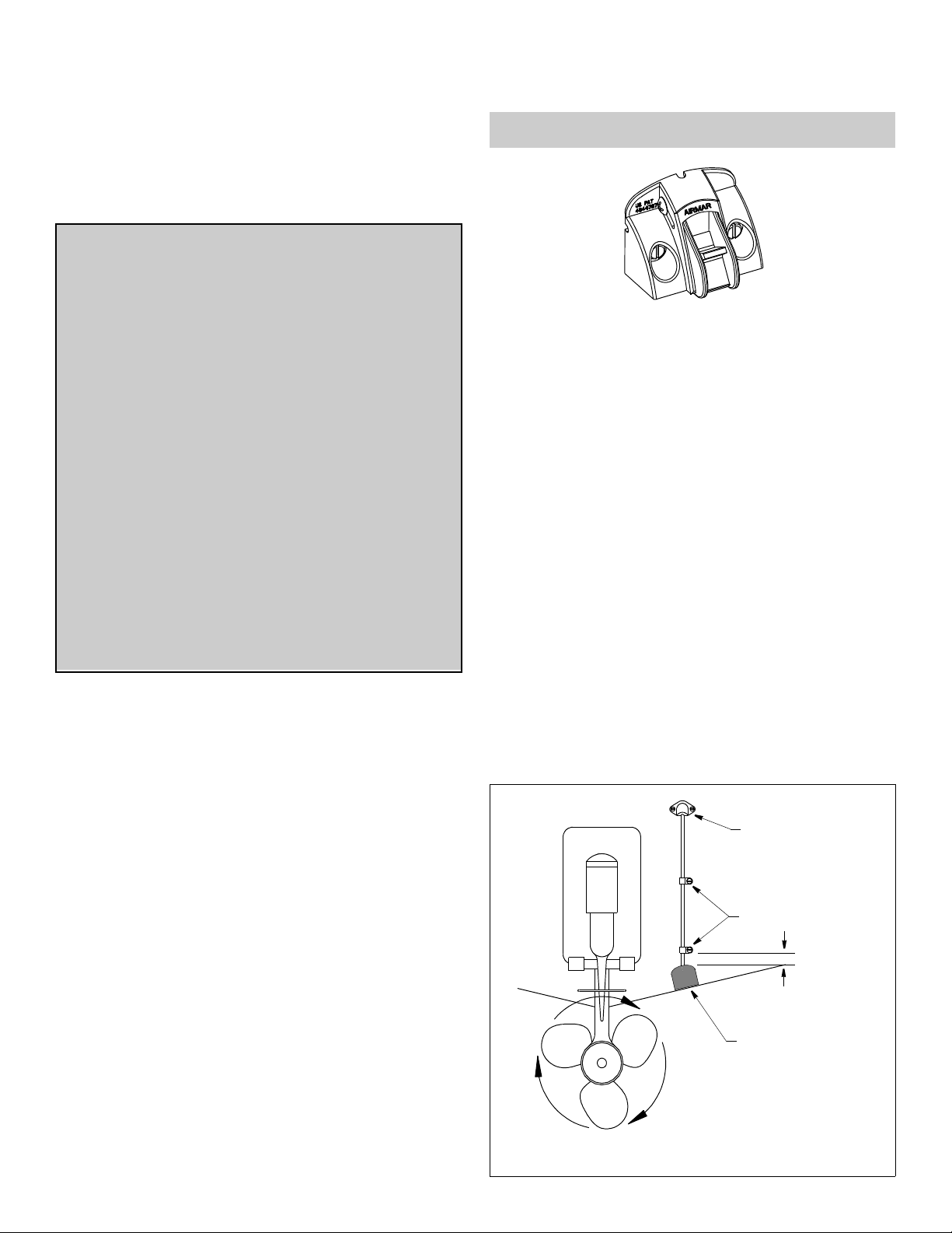
Mounting Location
CAUTION: Do not mount in an area of turbulence or bubbles:
near water intake or discharge openings; behind strakes, struts,
fittings, or hull irregularities
CAUTION: Avoid mounting the sensor where the boat may be
supported during trailering, launching, hauling, or storage.
• For the best performance, the sensor must be in contact with
smooth water. To identify an area of clean water, observe the
water flow off the transom while the boat is underway.
• Mount the sensor as close to the centerline (keel) of the boat as
possible to ensure the sensor remains in the water when the
boat is turning.
• Single drive boat—Mount at least 75 mm (3") beyond the
swing radius of the propeller (see Figure 1). The starboard side
where the propeller blades are moving downward is preferred.
• Twin drive boat—Mount the sensor between the drives.
Tools & Materials
Safety goggles
Dust mask
Digital level
Screwdrivers
Weak solvent (alcohol)
Straight edge
Electric drill
Drill bits:
Mounting holes 5.4mm, #3, or 13/64"
Transom hole (optional) 20mm or 13/16"
Cable clamp holes 3mm or 1/8"
Masking tape
Marine sealant (suitable for below waterline)
Putty knife
Pencil
Zip-ties
Water-based antifouling paint (mandatory in salt water)
cable cover
cable clamps
50mm (2")
use double-sided tape
to hold the sensor
flush with the bottom
of the hull before installation
Figure 1. Mounting location on single drive boat
Page 2
transom
angle
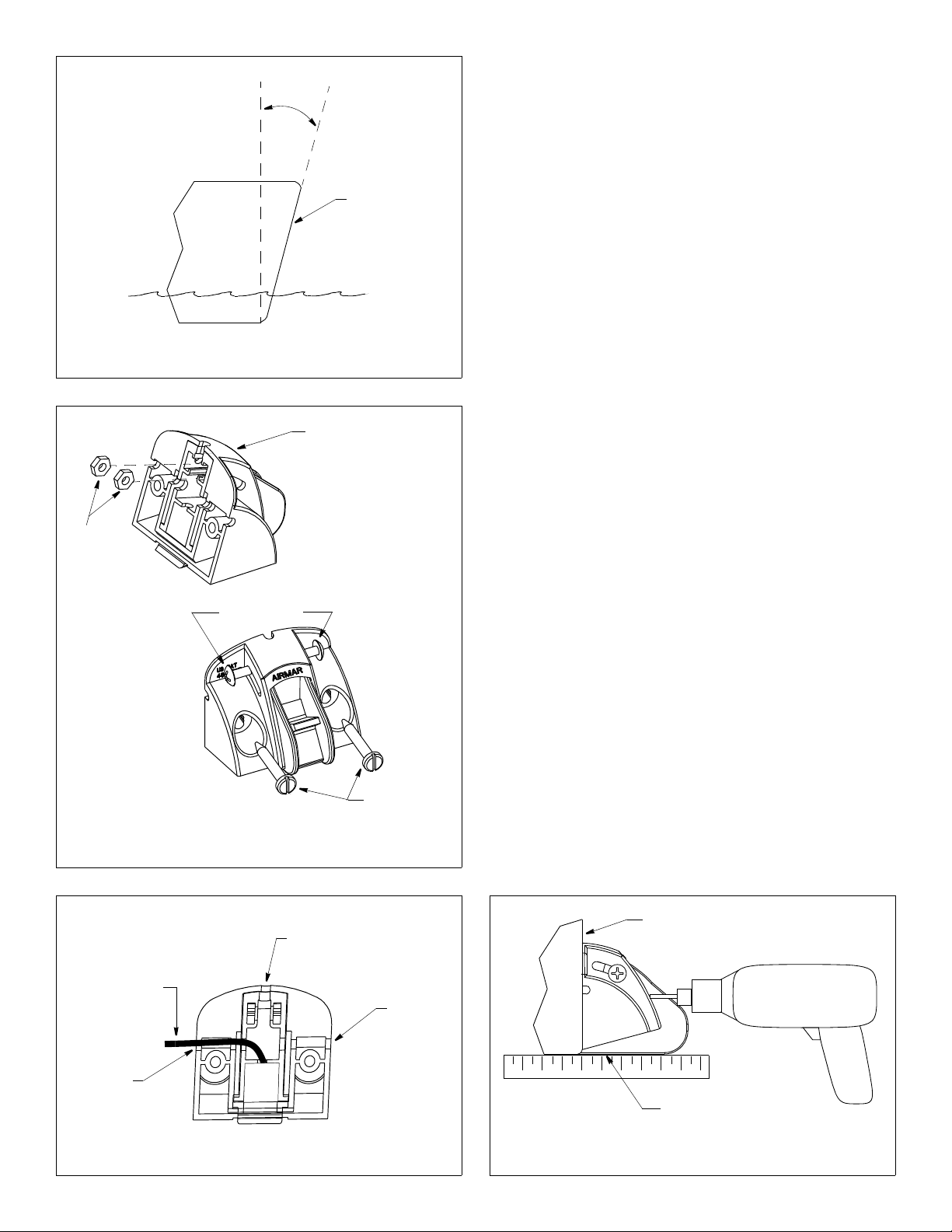
Installation
CAUTION: Measure and drill carefully, since the bracket is only
slightly adjustable.
perpendicular
to the waterline
transom
Figure 2. Measuring the transom angle
bracket
nuts
#8 adjustment
screws
#10 mounting
screws
Figure 3. Installing the adjustment and the mounting screws
CAUTION: To prevent drilling too deeply, wrap masking tape
around the bit 22mm (7/8") from the point.
CAUTION: Fiberglass hull—Minimize surface cracking by
running the drill in reverse until the gelcoat is penetrated.
NOTE: If the adjustable paddlewheel assembly separates from
the bracket, refer to Figure 10 on page 4 to reassemble.
Preparation
1. Measure the transom angle of the hull at the selected location
using a digital level (see Figure 2).
2. Insert the two nuts into the slots in the back of the bracket.
Install the #8 adjustment screws (see Figure 3).
Do not tighten the screws at this time.
3. There are three possible cable exits in the back of the bracket:
left, center, and right (see Figure 4). Choose the best cable exit
for your installation and route the cable through the notches in
the back of the bracket.
Mounting
CAUTION: The bottom edge of the adjustable paddlewheel assembly (not the bracket) must be flush with the bottom of the hull.
1. The hull surface must be free of any dust, oil, grease, or loose
paint. Clean the selected location with a weak solvent (alcohol).
2. At the selected location and FLUSH with the bottom of the hull,
stick the double-sided tape to the transom (see Figure 1). Peel
off the remaining non-stick layer.
3. Holding a straight edge against the bottom of the hull, position
the sensor at the selected location (see Figure 5). The bottom
edge of the paddlewheel assembly (not the bracket) must
be flush with the bottom of the hull. Press the bracket firmly
in place. Use additional double-sided tape if necessary.
4. Using a 5.4mm, #3, or 13/64" drill bit, drill the two mounting holes
perpendicular to the transom. To prevent drilling too deeply, wrap
masking tape around the bit 13mm (1/2") from the point.
5. Apply marine sealant to the two, #10 x 1-1/4", mounting screws
to prevent water seeping into the transom. Screw the sensor to
the hull (see Figure 3). Check again that the bottom edge of the
paddlewheel assembly (not the bracket) is flush with the bottom
of the hull. If necessary, slide the bracket up or down. Tighten
the screws. Do not over tighten.
2
back view
cable routed
through a side
cable exit
cable exit
Figure 4. Routing the cable in the bracket
cable exit
cable exit
transom
adjustable paddlewheel
assembly (not the bracket)
is flush with the hull bottom
hold drill
perpendicular
to transom
Figure 5. Positioning the sensor
Page 3

Adjusting
CAUTION: Filling the gap between the sensor and the hull is
critical to the proper operation of the sensor.
1. Holding a straight edge against the bottom of the hull, push the
adjustable paddlewheel assembly down until it touches the
straight edge and is flush with the bottom of the hull (see Figure
6). Tighten the adjustment screws to 1/4 turn past snug. Do not
over tighten.
2. Fill the gap between the sensor and the hull with marine sealant
using a putty knife for smoothing (see Figure 7). Pay particular
attention to the transition from the hull to the adjustable
paddlewheel assembly. This will ensure smooth water flow over
the paddlewheel.
Testing on the Water
1. Become familiar with your echosounder’s performance at a
speed of 4kn (5MPH).
2. Gradually increase the boat speed and observe the gradual
decline in performance due to turbulent water flowing over the
transducer’s active surface.
3. If the decline in performance is sudden (not gradual), identify
the boat speed at which the onset occurred. Return the boat to
this speed, then gradually increase speed while making
moderate turns in both directions.
4. If the performance improves while turning to the side on which
the sensor is installed, the transducer’s position probably needs
adjustment. It is probably in aerated water.
To improve performance, try the following one at a time in the
order given.
a. Increase the sensor’s angle in the water. Tilt the adjustable
paddlewheel assembly down 2° - 3° or until it is 3mm (/8”)
lower than the bottom of the hull (see Figure 8).
b. Move the sensor deeper into the water if possible.
c. Move the sensor closer to the centerline of the boat.
Fill unused screw holes with marine sealant.
NOTE: High-speed operation [above 35kn (40MPH)] may
require less projection in the water to improve performance and
reduce the chance that water pressure will cause the bracket to
release.
5. Calibration—To match the speed shown on the display to the
actual speed of the boat, you may need to calibrate the
instrument. Refer to your instrument owner’s manual.
16° transom
3° transom
adjustment
screw (2)
marine
sealant
adjustment
screw (2)
push
Figure 6. Angle adjustment
Figure 7. Filling the gap
adjustable
paddlewheel
assembly
adjustable
paddlewheel
assembly
Cable Routing
CAUTION: Do not remove the connector to ease cable routing. If
the cable must be cut and spliced, use Airmar’s splash-proof
Junction Box No. 33-035 and follow the instructions provided.
Removing the waterproof connector or cutting the cable, except
when using a water-tight junction box, will void the sensor
warranty.
Route the sensor cable over the transom, through a drain hole, or
through a new hole drilled in the transom above the waterline.
1. If a hole must be drilled, choose a location well above the
waterline (see Figure 1). Check for obstructions such as trim
tabs, pumps, or wiring inside the hull. Mark the location with a
pencil. Drill a hole through the transom using the appropriate
size bit to accommodate the connector.
2. Route the cable over or through the transom.
push
adjustment
screw (2)
adjust
paddlewheel
assembly
33mm (1/8")
lower than
bottom of hull
Figure 8. Tilting the adjustable paddlewheel assembly
3
Page 4

3. On the outside of the hull secure the cable to the transom using
the cable clamps. Position one cable clamp 50mm (2") above
the bracket and mark the mounting hole with a pencil.
4. Position the second cable clamp halfway between the first
clamp and the cable hole. Mark this mounting hole.
5. If a hole has been drilled in the transom, open the appropriate
slot in the cable cover. Position the cover over the cable where
it enters the hull. Mark the two mounting holes.
6. At each of the marked locations, use a 3mm or 1/8" bit to drill a
hole 10mm (3/8") deep. To prevent drilling too deeply, wrap
masking tape around the bit 10mm (3/8") from the point.
7. Apply marine sealant to the threads of the #6 x 1/2" self-tapping
screws to prevent water from seeping into the transom. If you
have drilled a hole through the transom, apply marine sealant to
the space around the cable where it passes through the transom.
8. Position the two cable clamps and fasten them in place. If used,
push the cable cover over the cable and screw it in place.
9. Route the cable to the instrument being careful not to tear the
cable jacket when passing it through the bulkhead(s) and other
parts of the boat. To reduce electrical interference, separate the
sensor cable from other electrical wiring and the engine(s). Coil
any excess cable and secure it in place with zip-ties to prevent
damage.
10.Refer to your instrument owner’s manual to connect the sensor
to the instrument.
remove
adjustment
screws (2)
paddlewheel
shaft
Figure 9. Servicing
push
rotate
do not move
adjustable
paddlewheel
assembly
lower than
paddlewheel
shaft holes
Checking for Leaks
When the boat is placed in the water, immediately check for
leaks around the screws and any holes drilled in the hull. Note
that very small leaks may not be readily observed. Do not leave
the boat in the water unchecked for more than three hours.
Maintenance
Antifouling Paint
Aquatic growth can accumulate rapidly on the sensor’s surface
reducing performance within weeks. Surfaces exposed to salt
water that do not interlock must be coated with antifouling paint.
Use water-based antifouling paint only. Never use ketone based
paint since ketones can attack many types of plastic. Reapply
paint every 6 months or at the beginning of each boating season.
Servicing the Paddlewheel
CAUTION: Do not move the assembly past the shaft holes as any
gap filler will be damaged.
Clean the sensor with a soft cloth and mild household detergent. If
the paddlewheel becomes fouled or inoperable, remove it for
cleaning. Remove the two adjustment screws and push the
adjustable paddlewheel assembly down until the paddlewheel
shaft is exposed (see Figure 9). Do not move the assembly past
the shaft holes as any gap filler will be damaged. Push out the
paddlewheel shaft with a 1/16" punch. Use a stiff brush or putty
knife to remove the growth. In severe cases, wet sand the surface
with fine grade wet/dry paper.
Orient the short side of the paddlewheel blades as shown in
Figure 10. Slide the shaft through the holes in the adjustable
paddlewheel assembly and the paddlewheel. Be sure the ends of
the shaft are flush with the housing.
BOW
Figure 10. Orienting the paddlewheel
Sensor Replacement & Parts
The information needed to order a replacement sensor is printed
on the cable tag. Do not remove this tag. When ordering, specify
the part number and date. For convenient reference, record this
information on the top of page one.
Replace broken or worn parts immediately. The water-lubricated
paddlewheel bearings have a life of up to 5 years on low-speed
boats [less than 10knots (11MPH)] and 2 years on high-speed
vessels. Purchase Paddlewheel Kit 33-398.
Obtain parts from your instrument manufacturer or marine dealer.
Gemeco Tel: 803-693-0777
(USA) Fax: 803-693-0477
email: sales@gemeco.com
Airmar EMEA Tel: +33.(0)2.23.52.06.48
(Europe, Middle East, Africa) Fax: +33.(0)2.23.52.06.49
email: sales@airmar-emea.com
®
AIRMAR
TECHNOLOGY CORPORATION
4
35 Meadowbrook Drive, Milford, New Hampshire 03055-4613, USA
www.airmar.com
Copyright © 1997 2011 Airmar Technology Corp. All rights reserved.
 Loading...