

Page 1
INSTALLATION INSTRUCTIONSOWNER’S GUIDE &
Thru-Hull, Retractable with Valve
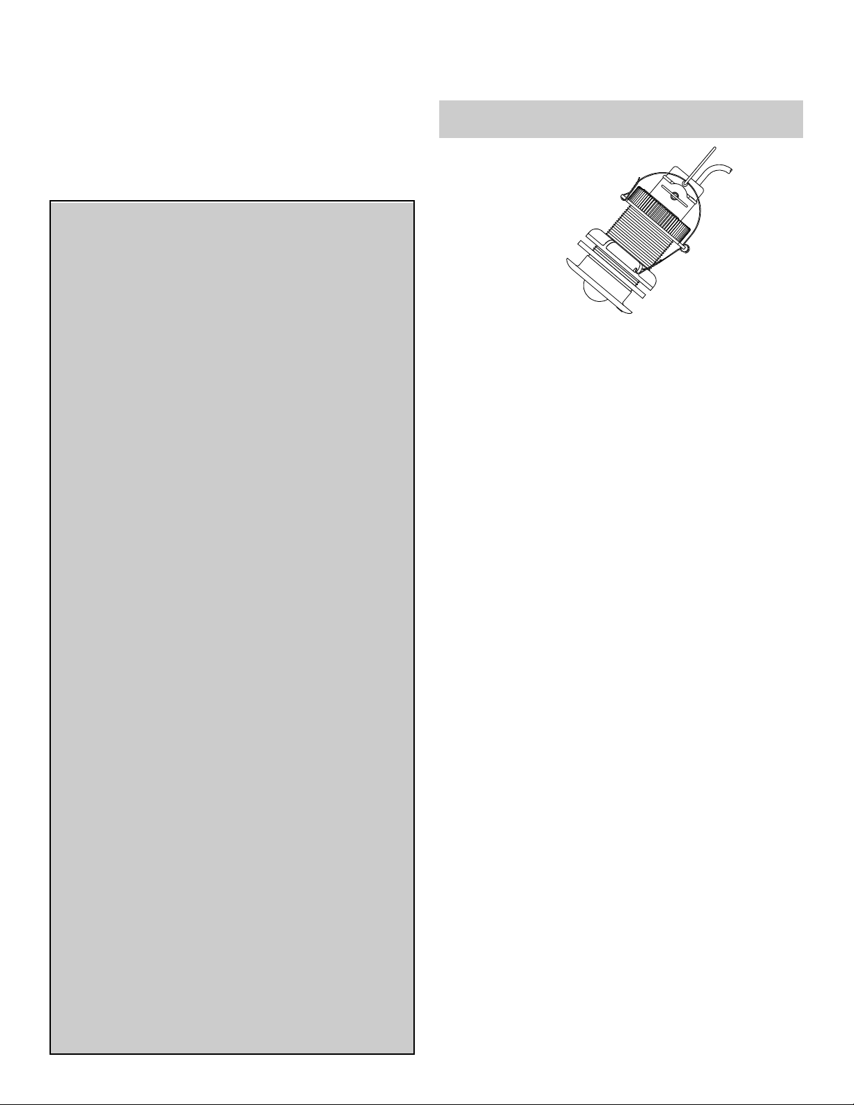
Speed & Temperature Sensor
Models: S650, ST650
Follow the precautions below for optimal product
performance and to reduce the risk of property
damage, personal injury, and/or death.
WARNING: Always wear safety goggles and a dust
mask when installing.
WARNING: The valve is not a watertight seal! Always
17-129 rev. 08 04/12/11
use the insert or long blanking plug secured with the
retaining pin, safety rings, and safety wire for a
watertight seal.
WARNING: The o-rings must be intact and well
lubricated to make a watertight seal.
WARNING: Always attach the safety wire to prevent the
insert or blanking plug from backing out in the unlikely
event that the cap nut fails or is screwed on incorrectly.
WARNING: Stainless steel housing in metal hull—Be
sure the washer contacts the hull. Do not tighten the
hull nut with the washer against the isolation bushing,
as the housing will not be firmly installed. If necessary,
sand the isolation bushing until the washer rests
against the hull.
WARNING: Immediately check for leaks when the boat
is placed in the water. Do not leave the boat unchecked
for more than three hours. Even a small leak may allow
considerable water to accumulate.
WARNING: When the valve assembly is removed,
always insert the short, emergency plug with the cap
nut secured with the safety wire for a watertight seal.
CAUTION: Never use a fairing with a plastic housing;
the protruding sensor would be vulnerable to damage
from impact.
CAUTION: Never install a metal housing on a vessel
with a positive ground system.
CAUTION: A stainless steel housing must be isolated
from a metal hull to prevent electrolytic corrosion. Use
the isolation bushing supplied.
CAUTION: Never pull, carry, or hold the sensor by its
cable; this may sever internal connections.
CAUTION: Never use solvents. Cleaners, fuel,
sealants, paint, and other products may contain
strong solvents, such as acetone, which attack many
plastics, greatly reducing their strength.
IMPORTANT: Please read the instructions
completely before proceeding with the installation.
These instructions supersede any other instructions
in your instrument manual if they differ.
Record the information found on the cable tag for future reference.
Part No._________________Date___________
P17
Low Profile
Plastic Housing
Applications
• Plastic housing recommended for fiberglass or metal hull only.
Never install a plastic housing in a wood hull, since swelling of
the wood may fracture the plastic.
• Bronze housing recommended for fiberglass or wood hull.
Never mount a bronze housing in a metal hull because
electrolytic corrosion will occur.
• Stainless steel housing compatible with all hull materials.
Recommended for aluminum hulls to prevent electrolytic corrosion
provided the stainless steel housing is isolated from the metal hull.
Tools & Materials
Safety goggles
Dust mask
Water-based anti-fouling paint (mandatory in salt water)
Electric drill with 10mm (3/8") or larger chuck capacity
Drill bit: 3mm or 1/8"
Hole saw: 51mm or 2" (plastic or bronze housing)
57mm or 2-1/4" (stainless steel housing in a metal hull)
Countersink tool (installing a flush housing)
Sandpaper
Mild household detergent or weak solvent (such as alcohol)
File (installation in a metal hull)
Marine sealant (suitable for below waterline)
Additional washer [for aluminum hull less than 6mm (1/4") thick]
Slip-joint pliers (installing a metal housing)
Grommet(s) (some installations)
Cable ties
Installation in a cored fiberglass hull (see page 3):
Hole saw for hull interior 60mm or 2-3/8"
Fiberglass cloth and resin
or Cylinder, wax, tape, and casting epoxy
Pretest
Connect the sensor to the instrument and spin the paddlewheel.
Check for a speed reading (and the approximate air temperature if
applicable). If there is no reading(s) or it is inaccurate, return the
product to the place of purchase.
Mounting Location
CAUTION: Do not mount the sensor near water intake or
discharge openings; behind strakes, fittings, or hull irregularities
that will disturb the water flow.
CAUTION: Never mount the sensor directly ahead of a depth
transducer, since turbulence generated by the paddlewheel’s
rotation will adversely affect the depth transducer’s performance,
especially at high speeds. Mount side by side.
Page 2
CAUTION: Do not mount in line with trailer rollers or bunks that
may damage the transducer’s face.
Turbulence-free water must flow under the paddlewheel at all
boat speeds. Choose an accessible spot inside the vessel. Allow
a minimum of 280mm (11") of headroom for the height of the
housing, tightening the nuts, and removing the insert.
• Displacement hull powerboats—Locate amidships near the
centerline.
• Planing hull powerboats—Mount well aft to ensure the sensor
is in contact with the water at high speeds.
• Fin keel sailboats—Mount on or near the centerline and
forward of the fin keel 300– 6 00 mm (1 –2').
• Full keel sailboats—Locate amidships and away from the keel
at the point of minimum deadrise.
Anti-fouling Paint
Aquatic growth can accumulate rapidly on the sensor’s surface
reducing performance within weeks. Surfaces exposed to salt
water must be coated with anti-fouling paint. Use water-based
anti-fouling paint only. Never use ketone based paint, since
ketones can attack many plastics possibly damaging the sensor.
It is easier to apply anti-fouling paint before installing the sensor,
but allow sufficient drying time. Reapply paint every 6 months or
at the beginning of each boating season. Paint the following
surfaces (see Figure 1):
• Outside wall of the paddlewheel insert below the lower o-ring
• Paddlewheel cavity
• Paddlewheel
• Exterior flange of the housing and valve assembly
• Bore of the valve assembly up 30 mm (1-1/4")
• Blanking plug below the lower o-ring including the exposed end
Installation
Hole Drilling
Cored fiberglass hull—Follow separate instructions on page 3.
1. Drill a 3mm or 1/8" pilot hole from inside the hull. If there is a rib,
strut or other hull irregularity near the selected mounting
location, drill from the outside.
2. Using the appropriate size hole saw, cut a hole perpendicular to the
hull from outside.
Flush housing—Use a countersink tool to create a ‘seat’ in the hull.
paddlewheel
housing
insert
outside wall
below
lower o-ring
paddlewheel
paddlewheel
cavity
bore of
valve assembly
up 30mm (1-1/4")
exterior flange
of housing and
valve assembly
Figure 1. Anti-fouling paint
Copyright © 1996 Airmar Technol ogy Corp.
3. Sand and clean the area around the hole, inside and outside, to
ensure that the sealant will adhere properly to the hull. If there is
any petroleum residue inside the hull, remove it with either mild
household detergent or a weak solvent (alcohol) before sanding.
Metal hull—Remove all burrs with a file and sandpaper.
Bedding
CAUTION: Be sure the surfaces to be bedded are clean and dry.
Apply a 2mm (1/16") thick layer of marine sealant around the
flange of the housing that contacts the hull and up the sidewall of
the housing (see Figure 2). The sealant must extend 6mm (1/4")
higher than the combined thickness of the hull, washer(s), and
hull nut. This will ensure there is sealant in the threads to seal the
hull and to hold the hull nut securely in place.
Stainless steel housing in a metal hull—To prevent electrolytic
corrosion, the stainless steel housing must be isolated from the
metal hull. Slide the isolation bushing onto the housing. Apply
additional sealant to the surfaces of the bushing that will contact
the hull, filling any cavities in and around the bushing
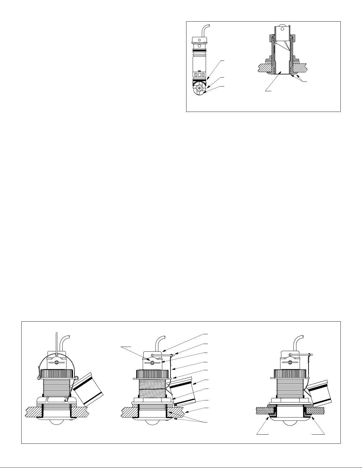
Installing
CAUTION: If your sensor came with a connector, do not remove it to
ease cable routing. If the cable must be cut and spliced, use Airmar’s
splash-proof Junction Box 33-035 and follow the instructions provided.
Removing the waterproof connector or cutting the cable, except when
using a watertight junction box, will void the sensor’s warranty.
1. From outside the hull, push the housing into the mounting hole
using a twisting motion to squeeze out excess sealant (see
plastic housing
2
(P17 shown) stainless steel housing (SS557 shown)
bronze housing (B17 shown)
paddlewheel insert
retaining
pin
Figure 2. Bedding and installing (low profile housings shown)
Copyright © 1996 - 2002 Airmar Techno logy Corp.
pull ring
safety ring (2)
safety wire
cap nut (plastic)
emergency plug
hull nut
washer
hull
marine sealant
on flange and sidewall
in metal hull
isolation bushing
with marine sealant
Page 3
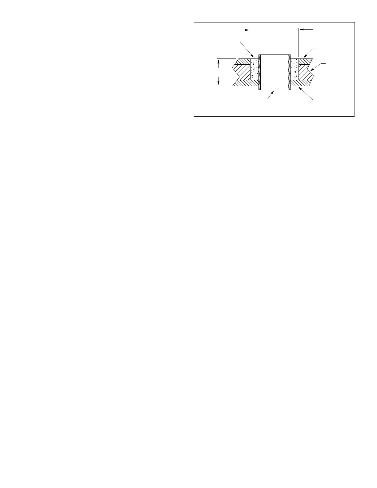
Figure 2). Align the arrow on the flange of the housing to point
forward toward the bow. If the sensor is not installed on the
centerline, angle the housing slightly toward the centerline to
align it with the water flow.
2. From inside the hull, slide the washer onto the housing.
Aluminum hull less than 6mm (1/4") thick—Use an additional
rubbery, fiberglass, or plastic washer. Never use wood since it will swell,
possibly fracturing the plastic housing. Never use bronze since
electrolytic corrosion will occur.
Stainless steel transducer in metal hull—Be sure the washer contacts
the hull. Do not tighten the hull nut with the washer against the isolation
bushing, as the housing will not be firmly installed. If necessary, sand the
isolation bushing until the washer rests against the hull.
3. Screw the hull nut in place being sure the notch on the upper rim
of the housing and the corresponding arrow on the flange are still
pointing forward toward the bow.
Plastic housing—Do not clamp tightly on the wrenching flats, causing
the housing to fracture.
Plastic hull nut—Hand-tighten only. Do not over-tighten.
Metal hull nut—Tighten with slip-joint pliers.
Cored fiberglass hull—Do not over tighten, crushing the hull.
Wood hull—Allow the wood to swell before tightening the hull nut.
4. Remove any excess sealant on the outside of the hull to ensure
smooth water flow under the paddlewheel.
5. After the sealant cures, inspect the o-rings on the valve
assembly (replace if necessary) and lubricate them with the
silicone lubricant supplied (see Figure 4). The o-rings must be
intact and well lubricated to make a watertight seal.
6. Slide the valve assembly into the housing being sure to engage
the key in the notch. Screw the plastic cap nut in place and
hand tighten only. Do not over tighten.
7. Attach one pull ring to the paddlewheel insert. Similarly, attach
a pull ring to the blanking plug.
8. Inspect the o-rings on the paddlewheel insert (replace if
necessary) and lubricate them with the silicone lubricant supplied.
9. Slide the paddlewheel insert into the housing with the arrows on
the top pointing forward toward the bow. Seat it into place with a
pushing twisting motion until the keys fit into the notches. The
arrows on the top of the insert, the notch in the housing, and the
arrow on the flange will be aligned. Be careful not to rotate the
housing and disturb the sealant.
10.Attach one safety ring to one end of the retaining pin. Slide the
retaining pin through the valve assembly and paddlewheel insert.
Attach the second safety ring to the retaining pin (see Figure 2).
11.Attach the safety wire to prevent the insert from backing out in the
unlikely event that the cap nut fails or is screwed on incorrectly.
Plastic housing—Attach the safety wire to one eye in the hull nut.
Thread the short emergency plug onto the wire. Keeping the wire taut
throughout, lead the wire in a counterclockwise direction and thread it
through one eye in the cap nut. Thread the wire through the eye a
second time. Then lead the wire through the pull ring and the second eye
in the cap nut. Twist the wire securely to itself.
Metal housing—Wrap one end of the safety wire tightly around the housing
and twist it together with the long end. Thread the short emergency plug
onto the wire. Keeping the wire taut throughout, lead the wire straight up and
through one eye in the cap nut. Loop the wire through the pull ring and twist
it securely to itself.
12.Route the cable to the instrument being careful not to tear the
cable jacket when passing it through the bulkhead(s) and other
parts of the boat. Use grommets to prevent chafing. To reduce
electrical interference, separate the sensor cable from other
electrical wiring and the engine. Coil any excess cable and
secure it in place with cable ties to prevent damage.
13.Refer to the instrument owner’s manual to connect the sensor
to the instrument.
9- 12 mm
pour in
casting
epoxy
hull thickness
solid or hollow cylinder
Figure 3. Preparing a cored fiberglass hull
(3/8-1/2")
larger than the
hole through the
hull’s outer skin
Copyright © 1996 Airmar Technolog y Corp.
inner skin
core
outer skin
Checking for Leaks
When the boat is placed in the water, immediately check around
the thru-hull sensor for leaks. Note that very small leaks may not
be readily observed. Do not to leave the boat in the water
unchecked for more than 3 hours. If there is a small leak, there
may be considerable bilge water accumulation after 24 hour. If a
leak is observed, repeat “Bedding” and “Installing” immediately
(see on page 2).
Installation in a Cored Fiberglass Hull
The core (wood or foam) must be cut and sealed carefully. The core must
be protected from water seepage, and the hull must be reinforced to
prevent it from crushing under the hull nut allowing the housing to become
loose.
CAUTION: Completely seal the hull to prevent water seepage into
the core.
1. Drill a 3mm or 1/8" pilot hole from inside the hull. If there is a rib, strut,
or other hull irregularity near the selected mounting location, drill from
the outside. (If the hole is drilled in the wrong location, drill a second hole
in a better location. Apply masking tape to the outside of the hull over the
incorrect hole and fill it with epoxy.)
2. Using the 51mm or 2" hole saw, cut the hole from outside the hull
through the outer skin only (see Figure 3).
3. From inside the hull, use the 60mm or 2-3/8" hole saw to cut through
the inner skin and most of the core. The core material can be very soft.
Apply only light pressure to the hole saw after cutting through the inner
skin to avoid accidentally cutting the outer skin.
4. Remove the plug of core material so the inside of the outer skin and the
inner core of the hull are fully exposed. Sand and clean the inner skin,
core, and the outer skin around the hole.
5. If you are skilled with fiberglass, saturate a layer of fiberglass cloth with
a suitable resin and lay it inside the hole to seal and strengthen the
core. Add layers until the hole is the correct diameter.
Alternatively, a hollow or solid cylinder of the correct diameter can be
coated with wax and taped in place. Fill the gap between the cylinder and
hull with casting epoxy. After the epoxy has set, remove the cylinder.
6. Sand and clean the area around the hole, inside and outside, to ensure
that the sealant will adhere properly to the hull. If there is any petroleum
residue inside the hull, remove it with either mild household detergent
or a weak solvent (alcohol) before sanding.
7. Proceed with “Bedding” and “Installing” on page 2.
Operation, Maintenance, Repair & Parts
How the Valve Works
The valve is not a watertight seal! The sensor incorporates a selfclosing valve which minimizes the flow of water into the vessel when the
paddlewheel insert is removed. The curved flap valve is activated by both
a spring and water pressure. Water pushes the flap valve upward to block
the opening so there is no gush of water into the boat. Always install the
paddlewheel insert or the long blanking plug secured with the retaining
pin, safety rings, and safety wire for a watertight seal.
3
Page 4

Using the Long Blanking Plug
To protect the paddlewheel, use the long blanking plug when the boat will
be kept in salt water for more than a week, the boat will be removed from
the water, or aquatic growth build-up on the paddlewheel is suspected due
to inaccurate readings from the instrument.
1. Inspect the o-rings on the long blanking plug (replace if necessary) and
lubricate them with the silicone lubricant supplied or petroleum jelly
(Vaseline
®
) (see Figure 4). The o-rings must be intact and well
lubricated to make a watertight seal.
2. Remove the paddlewheel insert from the housing by removing the
safety wire, one safety ring, and the retaining pin.
Do not remove the cap nut (see Figure 2).
3. Grasp the pull ring and remove the paddlewheel insert with a slow
pulling motion.
NOTE: In the unlikely event that the paddlewheel insert cannot be
removed, see “Servicing the Valve Assembly” on page 4.
4. Slide the long blanking plug into the housing with the arrows on the top
pointing forward toward the bow. Seat it into place with a pushing
twisting motion until the keys fit into the notches (see Figure 4). Secure
it with the retaining pin, safety rings, and safety wire (see Figure 2).
Servicing the Paddlewheel Insert
Aquatic growth can impede or freeze the paddlewheel’s rotation and must
be removed. Clean the surface using a Scotch-Brite® scour pad and mild
household detergent. If fouling is severe, push the paddlewheel shaft out
using a spare shaft or a 4D finish nail with a flattened point. Then, lightly
wet sand the surface with fine grade wet/dry paper.
The water lubricated paddlewheel bearings have a life of up to 5 years on
low-speed boats [less than 10kn (11MPH)] and 1 year on high-speed
vessels. Paddlewheels can fracture and shafts can bend due to impact
with water borne objects and mishandling in boat yards. o-rings must be
free of abrasions and cuts to ensure a watertight seal. A replacement
Paddlewheel Kit 33-113 is available.
1. Using the new paddlewheel shaft, push the old shaft out about 6 mm (1/
4"). With pliers, remove the old shaft (see Figure 4).
2. Place the new paddlewheel in the cavity with the flat side of the blade
facing the same direction as the arrows on the top of the insert.
3. Tap the new shaft into place until the ends are flush with the insert.
4. Install two of the small o-rings.
5. Place the remaining two small o-rings on the long blanking plug.
Servicing the Valve Assembly
Should the valve fail, remove it for servicing. A replacement Paddlewheel
& Valve Kit 33-415 is available.
WARNING: If the insert is caught in the valve assembly trapping the cap
nut, temporarily hold the short emergency plug in place with the safety
wire. Then separate the insert from the valve assembly. If they cannot be
separated and the sensor must be left unattended, cut the cable to free
the cap nut [a minimum of 1m (3') from the insert]. Later, splice the cable
using Airmar’s Junction Box 33-035.
1. Remove the short emergency plug from the safety wire (see Figure 2).
2. Inspect (replace if necessary) and lubricate the o-ring with silicone
lubricant or petroleum jelly (Vaseline®). The o-ring must be intact and
well lubricated to make a watertight seal.
3. Unscrew the cap nut. With the short emergency plug ready in one hand,
remove the paddlewheel insert and valve assembly as one unit by
pulling upward on the pull ring. Rapidly insert the short emergency plug
to minimize the flow of water into the boat.
NOTE: The plug is not secure until the cap nut is in place.
4. To free the cap nut, remove the paddlewheel insert from the valve
assembly by removing one safety ring and the retaining pin. Grasp the
insert by the pull ring and pull slowly upward.
5. Secure the short emergency plug with the cap nut. Hand-tighten only.
Do not overtighten. Reattach the safety wire.
6. Clean, repair, or replace the valve assembly, so the flap valve moves
freely and seats against the valve housing (see Figure 4).
7. To reinstall the valve assembly and paddlewheel insert, inspect
(replace if necessary) and lubricate all the o-rings with silicone lubricant
or petroleum jelly. The o-rings must be intact and well lubricated to
make a watertight seal.
top view of
paddlewheel insert
notches
& blanking plug
paddlewheel
insert
valve
assembly
pull ring
small
o-rings
shaft
flat side of
blade
faces bow
key (2)
cap nut
large o-ring
flap valve
valve housing
medium
o-ring
blanking
plug
housing
BOW ►
Figure 4. Servicing
Copyright © 1996 - 2002 Airmar Te chnology Corp.
8. Remove the safety wire and cap nut from the short emergency plug.
With the valve assembly ready in one hand, remove the emergency
plug. Rapidly slide the valve assembly being sure to engage the key in
the notch of the housing. Then slide the paddlewheel insert into the
valve assembly with the arrows on the top pointing forward toward the
bow. Seat it into place with a pushing twisting motion until the keys fit
into the notches. Screw the cap nut in place and hand-tighten only. Do
not over tighten. Reattach the safety wire.
Winterizing
After the boat has been hauled for winter storage, remove the blanking
plug to let the water drain away before reinserting it. This will prevent any
water from freezing around the blanking plug and possibly cracking it.
Replacement Sensor & Parts
The information needed to order a replacement Airmar transducer is
printed on the cable tag. Do not remove this tag. When ordering, specify
the part number and date. For convenient reference, record this information
on the top of page one.
Part Airmar Part Number
Blanking Plug 33-376-01
Paddlewheel Kit 33-113
Paddlewheel & Valve Kit 33-415
Cap Nut 04-234-1 (plastic)
Hull Nut 04-004 (plastic)
Isolation Bushing 04-186-1
Housing, Nut & Washer 33-100 (bronze, low profile, B17)
Obtain parts from your instrument manufacturer or marine dealer.
Gemeco Tel: 803-693-0777
(USA) Fax: 803-693-0477
Airmar EMEA Tel: +33.(0)2.23.52.06.48
(Europe, Middle East, Africa) Fax: +33.(0)2.23.52.06.49
AIRMAR Technology Corporationwww.airmar.com
02-131-01 (bronze)
02-030 (bronze)
33-224-01 (bronze, flush, B21)
33-094-01 (stainless steel, SS557)
33-217 (plastic, flush, P217)
email: sales@gemeco.com
email: sales@airmar-emea.com
 Loading...