

Page 1
Paddlewheel & Valve Kit 33-415
Fits Models: S650, ST650
Follow the precautions below for optimal product
performance and to reduce the risk of property damage,
personal injury, and/or death.
INSTALLATION INSTRUCTIONSOWNER’S GUIDE &
IMPORTANT -
WARNING:
WARNING: Always wear safety goggles and a dust
mask when installing.
17-127-01 rev. 03 04/12/11
WARNING: The valve is not a watertight seal! Always
use the insert or long blanking plug secured with the
retaining pin, safety rings, and safety wire for a
watertight seal.
WARNING: The o-rings must be intact and well
lubricated to make a watertight seal.
WARNING: Always attach the safety wire to prevent
the insert or blanking plug from backing out in the
unlikely event that the cap nut fails or is screwed on
incorrectly.
WARNING: When the valve assembly is removed,
always insert the emergency plug with the CAP NUT
and safety wire for a watertight seal.
WARNING: If the paddlewheel insert is caught in the
valve assembly trapping the cap nut, TEMPORARILY
hold the short emergency plug in place with the safety
wire. Then, separate the paddlewheel insert from the
valve assembly. If they cannot be separated and the
sensor must be left unattended, cut the cable [a
minimum of 1m (3') from the insert] to free the cap nut.
Later splice the cable with a watertight junction box.
CAUTION: Never use solvents. Cleaners, fuel,
sealants, paint, and other products may contain strong
solvents, such as acetone, which attack many
plastics, greatly reducing their strength.
IMPORTANT: Please read the instructions completely
before proceeding with the installation. These
instructions supersede any other instructions in your
instrument manual if they differ.
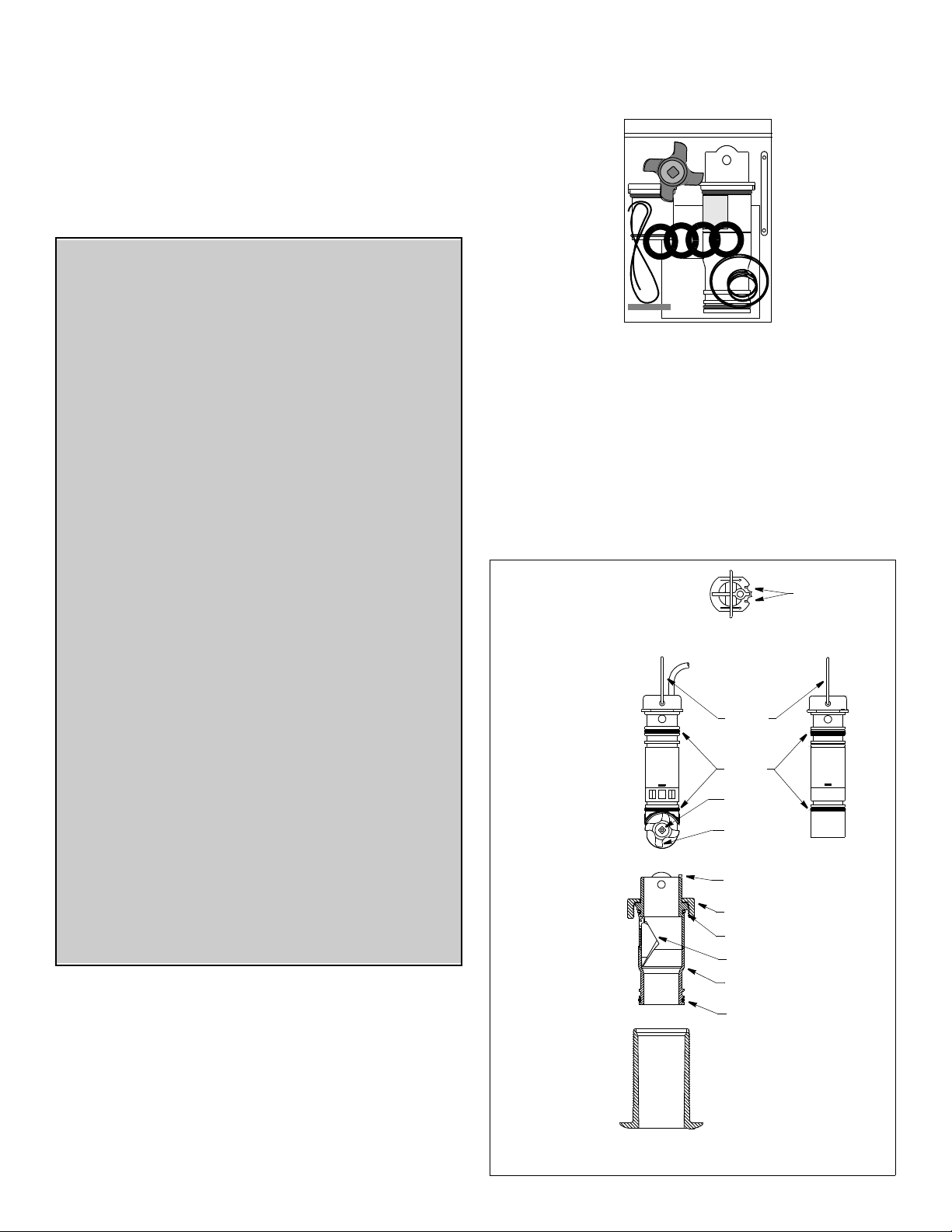
Servicing Paddlewheel Insert & Blanking Plug
1. Use the new paddlewheel shaft to push the old shaft out about
6mm (1/4"). With pliers remove the old shaft (see Figure 1).
2. On the insert, remove any aquatic growth using a stiff brush or
putty knife. Clean the surface with mild household detergent. If
fouling is severe, lightly wet sand with fine grade wet/dry paper.
4. Tap the new shaft into place until the ends are flush with the
insert.
5. Replace the two small o-rings on the paddlewheel insert and
lubricate them with the silicone lubricant supplied. O-rings must
be intact and well lubricated to make a watertight seal.
6. Replace the two o-rings on the long blanking plug.
7. Re-install the paddlewheel insert with the arrows on the top
pointing forward toward the bow. Seat it into place with a
twisting motion until the keys fit into the notches. Secure the
insert with the retaining pin and safety rings (see Figure 2).
top view of
paddlewheel insert &
blanking plug
paddlewheel
insert
valve
assembly
housing
pull ring
small
o-rings
shaft
flat side of
blade
faces bow
key (2)
cap nut
large o-ring
flap valve
valve housing
medium o-ring
notches
blanking
plug
BOW ►
3. Place the new paddlewheel in the cavity with the flat side of the
blade facing the same direction as the arrows on the top of the
insert.
Figure 1. Servicing
Copyright © 1999 - 2011 Airmar Technol ogy Corp.
Page 2
plastic housing stainless steel housing
large o-ring
emergency
plug
medium o-ring
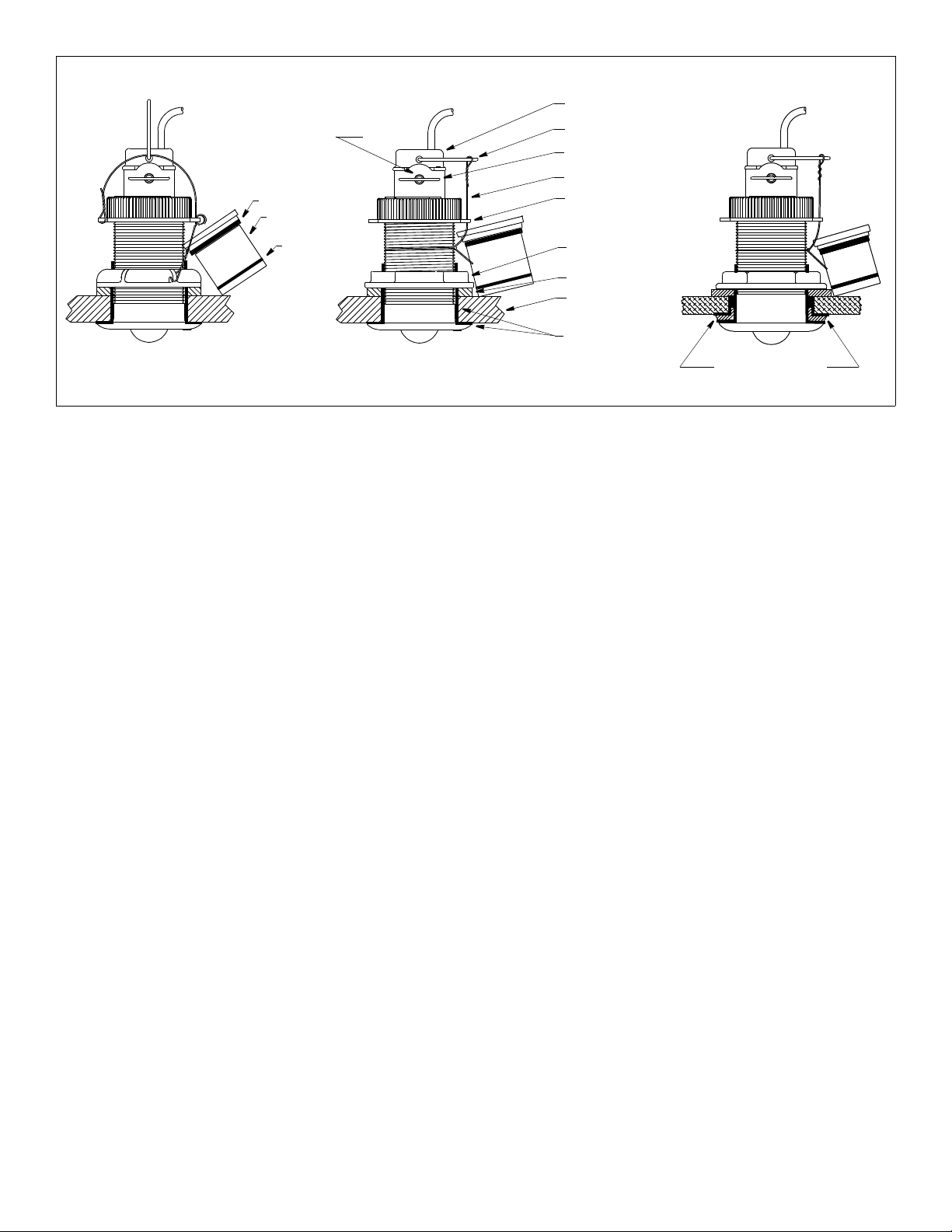
Figure 2. Installation (low profile housings shown)
metal housing
in non-metal hull
retaining
pin
Copyright © 1999 - 2010 Airmar Te chnology Corp.
paddlewheel insert
pull ring
safety ring (2)
safety wire
cap nut (plastic)
hull nut
washer
hull
marine sealant
on lip and sidewall
in metal hull
isolation bushing
with marine sealant
8. Attach the safety wire to prevent the insert from backing out in
the unlikely event that the cap nut fails or is screwed on
incorrectly..
Plastic housing—Attach the safety wire to one eye in the hull nut.
Thread the emergency plug onto the wire. Keeping the wire taut
throughout, lead it in a counterclockwise direction and thread it
through one eye in the cap nut. Thread the wire through the eye a
second time. Then lead the wire through the pull ring and the
second eye in the cap nut. Twist the wire securely to itself.
Metal housing—Wrap one end of the safety wire tightly around
the housing and twist it together with the long end. Thread the
emergency plug onto the wire. Keeping the wire taut throughout,
lead it straight up and through one eye in the cap nut. Loop the
wire through the pull ring and twist it securely to itself.
Replacing the Valve Assembly
1. On the replacement short emergency plug, inspect (replace if
necessary) and lubricate the o-rings with silicone lubricant or
petroleum jelly (Vaseline®) (see Figure 2). O-rings must be
intact and well lubricated for a watertight seal.
2. Remove the old emergency plug from the safety wire and
discard it.
3. Unscrew the cap nut. With the replacement short emergency
plug ready in one hand, remove the paddlewheel insert and
valve assembly as one unit by pulling upward on the pull ring.
Rapidly install the short emergency plug to minimize the flow of
water into the boat.
NOTE: The plug is not secure until the cap nut is in place.
4. To free the cap nut, remove the paddlewheel insert from the
valve assembly by removing one safety ring and the retaining
pin. Grasp the insert by the pull ring and pull slowly upward.
NOTE: If the paddlewheel insert is caught in the valve
assembly trapping the cap nut, TEMPORARILY hold the short
emergency plug in place with the safety wire. Then, separate
the paddlewheel insert from the valve assembly. If they cannot
be separated and the sensor must be left unattended, cut the
cable [a minimum of 1m (3') from the insert] to free the cap nut.
Later splice the cable with Airmar’s Junction Box 33-035.
5. Secure the short emergency plug with the cap nut. Handtighten only. Do not over-tighten. Reattach the safety wire.
6. Separate the valve assembly from the paddlewheel insert.
Discard the old valve assembly (see Figure 1).
7. Check the replacement valve assembly to be sure the flap valve
moves freely and seats against the valve housing. Inspect
(replace if necessary) and lubricate the o-rings with silicone
lubricant or petroleum jelly (Vaseline®). The o-rings must be
intact and well lubricated to make a watertight seal.
8. Remove the safety wire and cap nut from the emergency plug.
With the valve assembly ready in one hand, remove the
emergency plug. Rapidly slide the valve assembly into the
housing with a pushing twisting motion to engage the key in the
notch. Screw the cap nut in place. Hand-tightening only. Do
not over tighten.
9. Re-install the paddlewheel insert (with lubricated o-rings) with
the arrows on the top pointing forward toward the bow. Seat it
into place with a pushing twisting motion until the keys fit into
the notches. Secure the insert with the retaining pin and safety
rings (see Figure 1).
10.Attach the safety wire to prevent the insert from backing out in
the unlikely event that the cap nut fails or is screwed on
incorrectly (see Figure 2).
Plastic housing—Attach the safety wire to one eye in the hull nut.
Thread the emergency plug onto the wire. Keeping the wire taut
throughout, lead it in a counterclockwise direction and thread it
through one eye in the cap nut. Thread the wire through the eye a
second time. Then lead the wire through the pull ring and the
second eye in the cap nut. Twist the wire securely to itself.
Metal housing—Wrap one end of the safety wire tightly around
the housing and twist it together with the long end. Thread the
emergency plug onto the wire. Keeping the wire taut throughout,
lead it straight up and through one eye in the cap nut. Loop the
wire through the pull ring and twist it securely to itself.
®
AIRMAR
2
TECHNOLOGY CORPORATION
35 Meadowbrook Drive, Milford, New Hampshire 03055-4613, USA
www.airmar.com
Copyright © 1999 - 2011 Airmar Technology Corp. All rights reserved.
 Loading...