

Page 1
INSTALLATION INSTRUCTIONSOWNER’S GUIDE &
Transom Mount
Speed & Temperature Sensor
Models: S61, S63
Follow the precautions below for optimal product
performance and to reduce the risk of property
damage, personal injury, and/or death.
WARNING: Always wear safety goggles and a dust
mask when installing
WARNING: When the boat is placed in the water,
immediately check for leaks around the screws and
17-032-01 rev. 02 04/12/11
any other holes drilled in the hull.
CAUTION: Never pull, carry, or hold the sensor by the
cable as this may sever internal connections.
CAUTION: Never strike the sensor.
CAUTION: Never use solvents. Cleaners, fuel, paint,
sealants, and other products may contain strong
solvents, such as acetone, which attack many plastics
greatly reducing their strength.
Record the information found on the cable tag for future reference.
Part No._________________Date___________
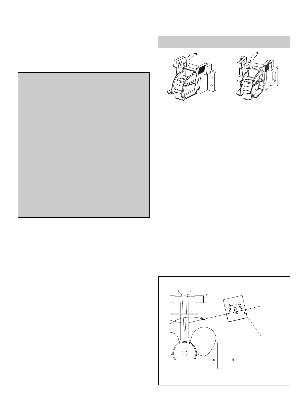
S61 with S63 with
bracket bracket
Pretest
Connect the sensor to the instrument and spin the paddlewheel.
Check for a speed reading and the approximate air temperature. If
there is no reading(s) or it is inaccurate, check the connections
and repeat the test. If there is still no reading(s) or it is inaccurate,
return the product to your place of purchase.
Mounting Location
CAUTION: Do not mount in an area of turbulence or bubbles:
near water intake or discharge openings; behind strakes, struts,
fittings, or hull irregularities
IMPORTANT: Please read the instructions completely
before proceeding with the installation. These
instructions supersede any other instructions in your
instrument manual if they differ.
Applications
• Not recommended for boats with large inboard engine(s).
• Designed for operation from 1–50kn (1 – 58 MPH).
• Fits transom angles from 13–20
fiberglass and aluminum boats).
For all other transom angles (including 3° transoms on jet boats
and vessels with stepped or undercut transoms) a tapered
plastic, wood, or metal shim must be fabricated.
• S63 can be snapped onto a P37, P52 or P55 transducer.
° (most powerboats and small
Tools & Materials
Safety goggles
Dust mask
Scissors
Masking tape
Electric drill
Drill bit, hole saw or spade bit for:
Bracket holes 4mm, #23 or 9/64"
Fiberglass hull only chamfer bit (preferred), 6mm or 1/4"
Transom hole (optional) 20mm or 13/16"
Cable clamp holes 3mm or 1/8"
Marine sealant (suitable for below waterline)
Screwdrivers
Putty knife
Pencil
Zip-ties
Water-based antifouling paint (mandatory in salt water)
CAUTION: Avoid mounting the sensor where the boat may be
supported during trailering, launching, hauling, or storage.
• For the best performance, the sensor must be in contact with
smooth water. To identify an area of clean water, observe the
water flow off the transom while the boat is underway.
• Mount the sensor as close to the centerline (keel) of the boat as
possible to ensure the sensor remains in the water when the
boat is turning.
• Single drive boat—Mount at least 75 mm (3") beyond the
swing radius of the propeller (see Figure 1). The starboard side
where the propeller blades are moving downward is preferred.
• Twin drive boat—Mount the sensor between the drives.
• Stepped transom—Mount the sensor on the step.
Align the
template’s fold
line with the hull
bottom and fold
under the hull
75mm (3")
min. beyond
swing radius of
propeller
Figure 1. Mounting location on single drive boat
Page 2
Place on starboard (right) side of boat
◄
keel
13° transom angle
Align with bottom
edge of transom
and fold under
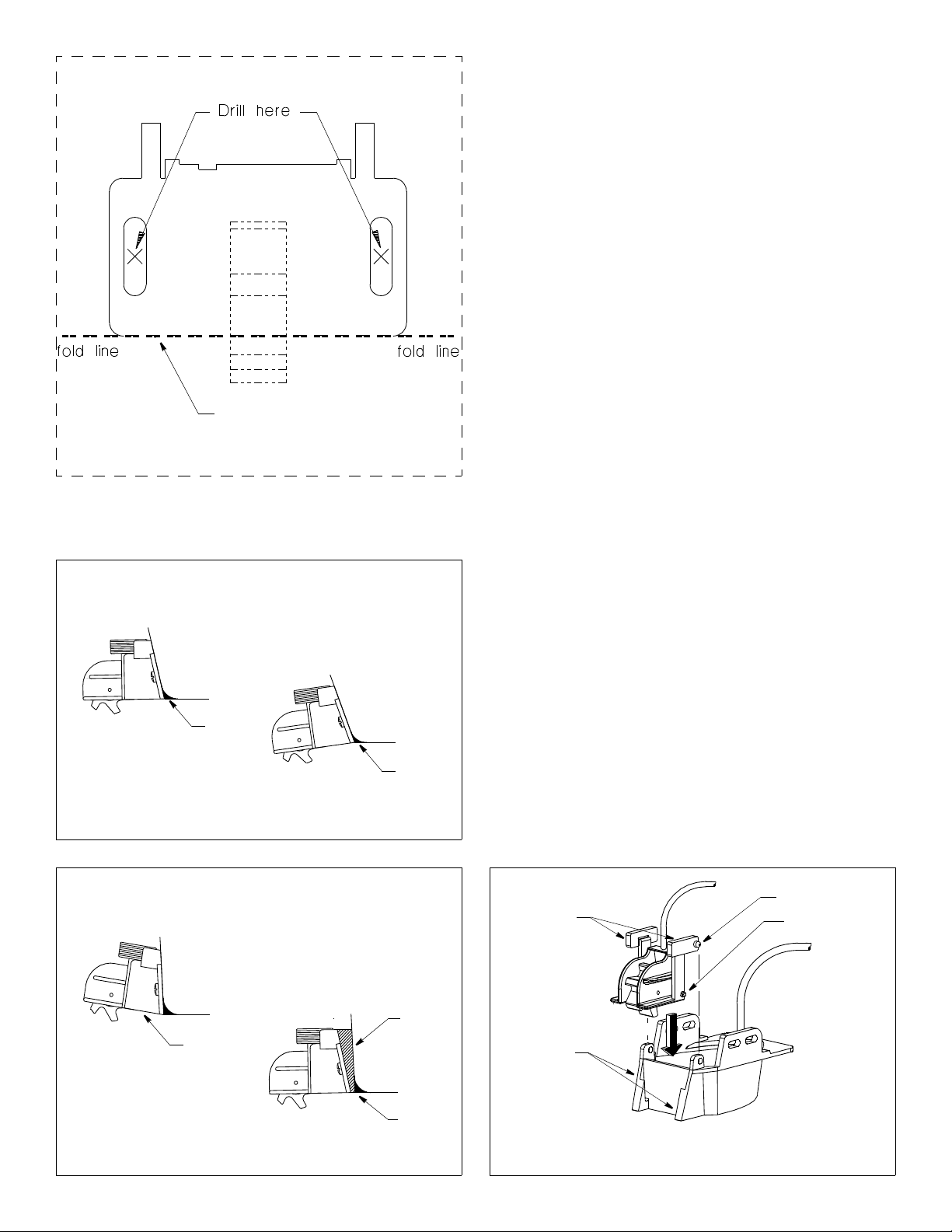
Figure 2. Template
20° transom angle
marine
sealant
Figure 3. Standard transom angles
marine
sealant
Installation
Mounting Directly to the Hull
CAUTION: Do not position the leading edge of the sensor lower
than the trailing edge because aeration will occur.
CAUTION: To prevent drilling too deeply, wrap masking tape
around the bit 22mm (7/8") from the point.
CAUTION: Fiberglass hull—Minimize surface cracking by
running the drill in reverse until the gelcoat is penetrated.
1. Cut-out the template printed on this page. Fold the template
along the fold-line (see Figure 2).
2. At the selected location, position the template so that the dotted
fold line is aligned with the bottom edge of the transom. Tape it
in place (see Figure 1).
3. Using a 4mm, #23 or 9/64" bit, drill two holes 22 mm (7/8") deep
at the location indicated. To prevent drilling too deeply, wrap
masking tape around the bit 1 mm (1/16") from the point.]
4. The bracket is designed for a transom angle from 13–20
Figure 3). For other transom angles, fabricate a custom shim
from plastic, an oily wood such as teak or metal (see Figure 4).
Then, mark and drill the shim.
5. Apply a marine sealant to the threads of the two #10 x 3/4" selftapping screws to prevent water seepage into the transom.
Slide a flat washer onto each screw and fasten the bracket (and
any shim) to the hull.
Do not tighten the screws completely at this time.
6. Using the vertical adjustment space on the bracket slots, slide
the sensor up or down until the bottom of the bracket is flush
with the underside of the hull. Tighten the screws.
7. Fill any gap between the sensor and the hull with marine
sealant using a putty knife for smoothing. This will ensure
smooth water flowing over the paddlewheel (see Figures 3
and 4).
Mounting to a Transducer
Install the transom mounted transducer following the instructions
provided with it. Then, insert the S63 into the guide rails on the
back of the transducer. Slide it down while squeezing the tabs
inward until the shear pins reach the bottom (see Figure 5).
Release the tabs to snap the locking pins into place.
Be sure all the pins are secure.
° (see
NO
3° transom angle
tabs
locking pins (2)
shear pins (2)
Shim required
(not provided)
shim
angle too
steep
Figure 4. Shim required
marine
sealant
guide rails
Figure 5. Installing an S63 on a transducer
2
Page 3

Cable Routing
CAUTION: Do not remove the connector to ease cable routing. If
the cable must be cut and spliced, use Airmar’s splash-proof
Junction Box No. 33-035 and follow the instructions provided.
Removing the waterproof connector or cutting the cable, except
when using a water-tight junction box, will void the sensor
warranty.
Route the sensor cable over the transom, through a drain hole or
through a new hole drilled in the transom above the waterline.
1. If a hole must be drilled, choose a location well above the
waterline. Check for obstructions such as trim tabs, pumps or
wiring inside the hull. Mark the location with a pencil. Drill a hole
through the transom using a 20 mm or 13/16” hole saw or spade
bit (to accommodate the connector).
2. Route the cable over or through the transom.
3. On the outside of the hull secure the cable to the transom using
the cable clamps. Position a cable clamp 50mm (2") above the
bracket and mark the mounting hole with a pencil (see Figure 6).
4. Position the second cable clamp halfway between the first
clamp and the cable hole. Mark this mounting hole.
5. If a hole has been drilled through the transom, open the
appropriate slot in the cable cover. Position the cover over the
cable where it enters the hull. Mark the two
mounting holes.
6. At each of the four marked locations, use a 3mm or 1/8" bit to
drill a hole 10mm (3/8") deep. [To avoid drilling too deeply, wrap
masking tape around the bit 10mm (3/8") from the point.]
7. Apply marine sealant to the threads of the four #6 x 1/2" selftapping screws to prevent water from seeping into the transom.
If you have drilled a hole in the transom, apply marine sealant to
the space around the cable leading through the transom.
8. Position the cable clamps and screw them in place. If used,
push the cable cover over the cable and screw it in place.
9. Route the cable to the instrument through the interior of the
boat. Be careful not to tear the cable jacket when passing it
through the bulkhead(s) and other parts of the boat. To reduce
electrical interference or “noise”, separate the sensor cable
from other electrical wiring. Coil any excess cable and secure it
in place with zip-ties to prevent damage.
10.Refer to your instrument owner’s manual to connect the sensor
to the instrument.
Checking for Leaks
When the boat is placed in the water, immediately check for
leaks around the screws and any holes drilled in the hull. Note
that very small leaks may not be readily observed. Do not leave
the boat in the water unchecked for more than three hours.
cable cover
cable clamps
50mm (2")
Figure 6. Routing the cable
Testing on the Water
1. Become familiar with your echosounder’s performance at a
speed of 4kn (5MPH).
2. Gradually increase the boat speed and observe the gradual
decline in performance due to turbulent water flowing over the
transducer’s active surface.
3. If the decline in performance is sudden (not gradual), identify
the boat speed at which the onset occurred. Return the boat to
this speed, then gradually increase speed while making
moderate turns in both directions.
4. If the performance improves while turning to the side on which
the sensor is installed, the transducer’s position probably needs
adjustment. It is probably in aerated water.
To improve performance, try the following one at a time in the
order given.
a. Increase the sensor’s angle in the water with a shim.
b. Move the sensor closer to the centerline of the boat.
Fill unused screw holes with marine sealant.
NOTE: High-speed operation [above 35kn (40MPH)] may
require less projection in the water to improve performance and
reduce the chance that water pressure will cause the bracket to
release.
5. Calibration—To match the speed shown on the display to the
actual speed of the boat, you may need to calibrate the
instrument. Refer to your instrument owner’s manual.
3
Page 4

Maintenance, Repair & Replacement
CAUTION: Remove the paddlewheel assembly before beaching,
trailering or hauling the boat, since these are the main causes of
speed sensor breakage.
Cleaning
Clean the sensor with a soft cloth and mild household detergent. If
the paddlewheel becomes fouled or inoperable, unsnap the
paddlewheel assembly for cleaning. Severe cases may require
removal of the paddlewheel. Using a small screwdriver, remove
the paddlewheel shaft retainers (see Figures 7 and 8). (If a
retainer is lost, a dab of RTV calk on the end of the shaft will
secure it.)
If necessary, use a stiff brush or putty knife to remove the growth.
Wet sanding is permissible with fine grade wet/dry paper. (If there
is a transducer, be careful to avoid scratching the face.)
Antifouling Paint
Aquatic growth can accumulate rapidly on the sensor’s surface
reducing performance within weeks. Surfaces exposed to salt
water that do not interlock, must be coated with antifouling paint.
Use water-based antifouling paint only. Never use ketone based
paint since ketones can attack many types of plastic. Reapply
paint every 6 months or at the beginning of each boating season.
Sensor Replacement & Parts
The information needed to order a replacement sensor is printed
on the cable tag. Do not remove this tag. When ordering, specify
the part number and date. For convenient reference, record this
information on the top of page one.
Replace broken or worn parts immediately. The water-lubricated
paddlewheel bearings have a life of up to 5 years on low-speed
boats [less than 10kn (11MPH)] and 2 years on high-speed
vessels.
The shear pins on the paddlewheel assembly are designed to
break if excessive force is applied to the speed sensor. For a
replacement S61 snap-in paddlewheel assembly without a cable
(the cable is mounted in the bracket) order part number 33-105
(see Figure 7). For the S63 with the cable mounted in the
paddlewheel assembly, order part number 33-110 (see Figure 8).
shear pins
shear
pin (2)
shaft retainer (2)
Figure 7. 33-105 Figure 8. 33-110
for the S61 for the S63
Obtain parts from your instrument manufacturer or marine dealer.
Gemeco Tel: 803-693-0777
(USA) Fax: 803-693-0477
email: sales@gemeco.com
Airmar EMEA Tel: +33.(0)2.23.52.06.48
(Europe, Middle East, Africa) Fax: +33.(0)2.23.52.06.49
email: sales@airmar-emea.com
shaft retainers
®
AIRMAR
TECHNOLOGY CORPORATION
35 Meadowbrook Drive, Milford, New Hampshire 03055-4613, USA
www.airmar.com
Copyright © 1998 2011 Airmar Technology Corp. All rights reserved.
4
 Loading...