

Page 1

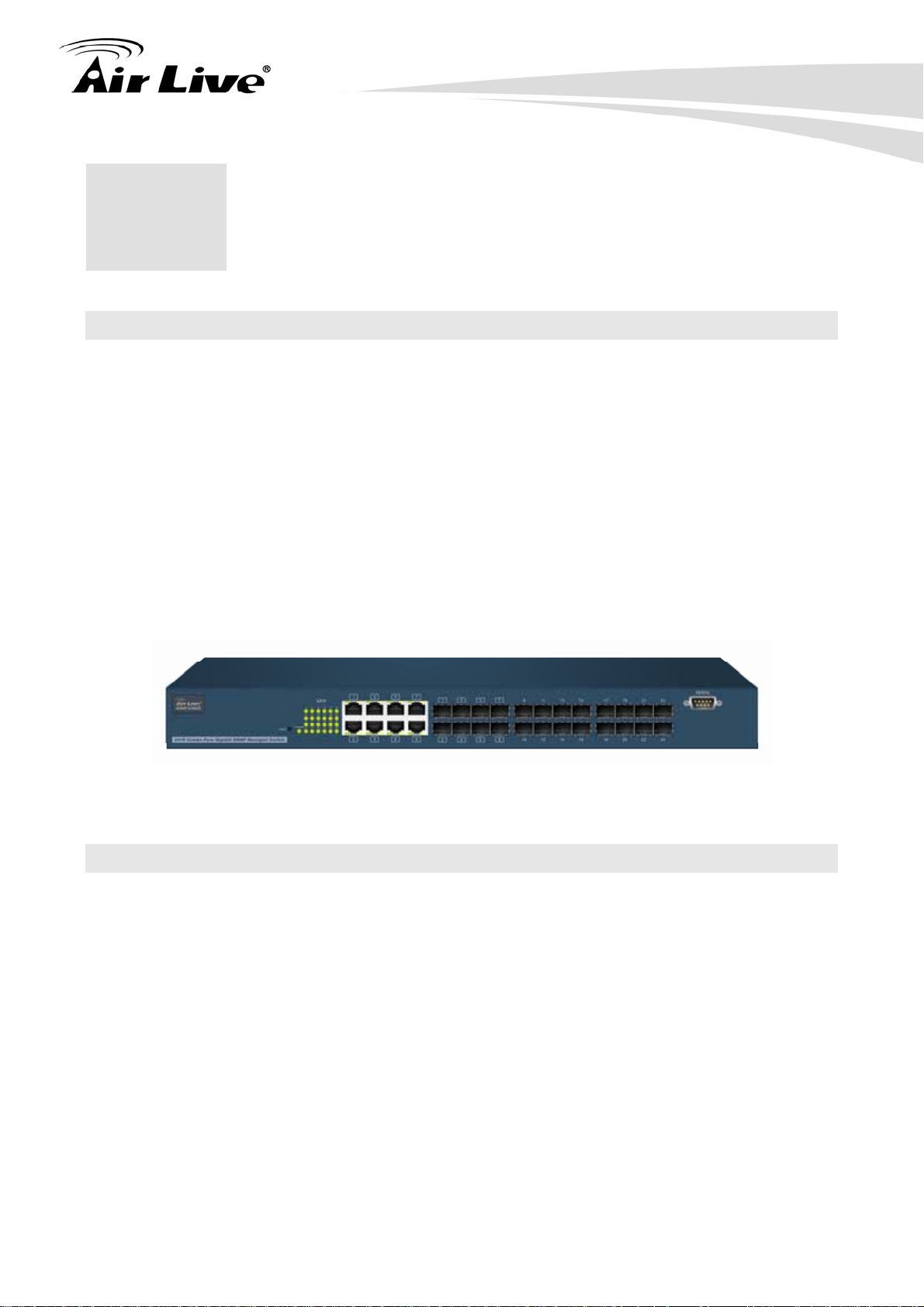
SNMP-24MGB
24+8 Combo Pure Gigabit
SNMP Managed Switch
User’s Manual
Page 2

Copyright and Disclaimer
Copyright & Disclaimer
No part of this publication may be reproduced in any form or by any means, whether
electronic, mechanical, photocopying, or recording without the written consent of OvisLink
Corp.
OvisLink Corp. has made the best effort to ensure the accuracy of the information in this
user’s guide. However, we are not liable for the inaccuracies or errors in this guide.
Please use with caution. All information is subject to change without notice
All Trademarks are properties of their respective holders.
AirLive SNMP-24MGB User’s Manual
Page 3

Page 4

Table of Contents
Table of Contents
1. Introduction................................................................................................1
1.1 Overview..............................................................................................1
1.2 How to Use This Guide........................................................................1
1.3 Firmware Upgrade and Tech Support ..................................................2
1.4 Features...............................................................................................3
2. Installing the SNMP-24MGB......................................................................5
2.2 Before You Start...................................................................................5
2.3 Package Content .................................................................................5
2.4 Optional Accessories ...........................................................................6
2.5 Knowing your SNMP-24MGB ..............................................................7
2.6 Hardware Installation ...........................................................................7
2.6.1 Attaching Rubber Feet.................................................................................7
2.6.2 Rack-mounted Installation ...........................................................................8
2.6.3 Power On.....................................................................................................9
2.7 LED Table ............................................................................................9
3. Configuring the SNMP-24MGB ...............................................................11
3.1 Important Information.........................................................................11
3.2 Prepare your PC ................................................................................11
3.3 Management Interface.......................................................................12
3.4 Introduction to Web Management......................................................15
3.4.1 Getting into Web Management ..................................................................15
4. Web Management in SNMP-24MGB .......................................................17
4.1 Menu Structure of SNMP-24MGB......................................................17
4.2 System...............................................................................................19
4.2.1 IP Configuration.........................................................................................19
4.2.2 Account Configuration................................................................................21
4.2.3 Time Configuration ....................................................................................22
4.2.4 IP Configuration.........................................................................................24
4.2.5 Loop Detection ..........................................................................................27
4.2.6 Management Policy ...................................................................................28
4.2.7 System Log................................................................................................31
4.2.8 Virtual Stack...............................................................................................32
i
AirLive SNMP-24MGB User’s Manual
Page 5

Table of Contents
4.3 Port ....................................................................................................34
4.3.1 Port Configuration......................................................................................34
4.3.2 Port Status .................................................................................................36
4.3.3 Simple Counter..........................................................................................40
4.3.4 Detail Counter............................................................................................42
4.3.5 Power Saving ............................................................................................45
4.4 VLAN .................................................................................................46
4.4.1 VLAN Mode ...............................................................................................46
4.4.2 Tag-based Group .......................................................................................47
4.4.3 Port-based Group ......................................................................................49
4.4.4 Ports ..........................................................................................................51
4.4.5 Port Isolation..............................................................................................52
4.4.6 Management..............................................................................................53
4.5 MAC...................................................................................................54
4.5.1 Mac Address Table ....................................................................................54
4.5.2 Static Filter.................................................................................................56
4.5.3 Static Forward............................................................................................56
4.5.4 MAC Alias ..................................................................................................57
4.5.5 MAC Table .................................................................................................58
4.6 GVRP.................................................................................................59
4.6.1 GVRP Configuration ..................................................................................60
4.6.2 GVRP Counter...........................................................................................62
4.6.3 GVRP VLAN Group Information ................................................................64
4.7 QoS....................................................................................................65
4.7.1 Port QoS Configuration..............................................................................65
4.7.2 QoS Control List ........................................................................................67
4.7.3 Rate Limiters .............................................................................................72
4.7.4 Storm Control.............................................................................................74
4.7.5 Wizard .......................................................................................................75
4.8 SNMP ................................................................................................84
4.9 ACL ....................................................................................................86
4.9.1 ACL Ports Configuration ............................................................................86
4.9.2 ACL Rate Limiter Configuration .................................................................88
4.9.3 Access Control List ....................................................................................89
4.9.4 Wizard .....................................................................................................119
4.10 IP MAC Binding..............................................................................127
4.10.1 IP MAC Binding Configuration ...............................................................127
4.10.2 IP MAC Binding Dynamic Entry .............................................................128
4.11 802.1X Configuration .....................................................................129
4.11.1 Server ....................................................................................................133
AirLive SNMP-24MGB User’s Manual
ii
Page 6

Table of Contents
4.11.2 Port Configuration ..................................................................................135
4.11.3 802.1X Status.........................................................................................137
4.11.4 802.1X Statistics ....................................................................................138
4.12 Trunking Configuration...................................................................139
4.12.1 Trunking Port Setting/Port......................................................................140
4.12.2 Aggregation View...................................................................................142
4.12.3 LACP system Priority.............................................................................143
4.13 STP Configuration..........................................................................144
4.13.1 STP Status.............................................................................................144
4.13.2 STP Configuration .................................................................................146
4.13.3 STP Port Configuration..........................................................................148
4.14 MSTP.............................................................................................151
4.14.1 MSTP Status..........................................................................................151
4.14.2 MSTP Region Config.............................................................................152
4.14.3 Instant View ...........................................................................................152
4.15 Mirror .............................................................................................159
4.16 Multicast.........................................................................................161
4.16.1 IGMP Mode ...........................................................................................161
4.16.2 IGMP Proxy ...........................................................................................162
4.16.3 IGMP Snooping .....................................................................................163
4.16.4 IGMP Membership.................................................................................164
4.16.5 MVR.......................................................................................................165
4.16.6 MVID......................................................................................................166
4.16.7 Group Allow ...........................................................................................167
4.16.8 MVR Group Membership .......................................................................168
4.17 Alarm Configuration .......................................................................169
4.17.1 Event .....................................................................................................170
4.17.2 Email......................................................................................................171
4.18 DHCP Snooping.............................................................................172
4.18.1 DHCP Snooping State ...........................................................................172
4.18.2 DHCP Snooping Entry ...........................................................................173
4.18.3 DHCP Snooping Client ..........................................................................174
4.19 Save / Store ...................................................................................175
4.19.1 Factory Default ......................................................................................176
4.19.2 Save Start ..............................................................................................176
4.19.3 Save user ..............................................................................................177
4.19.4 Restore user ..........................................................................................177
4.20 Export / Import ...............................................................................178
4.21 Diagnostics ....................................................................................179
iii
AirLive SNMP-24MGB User’s Manual
Page 7

Table of Contents
4.21.1 Diag .......................................................................................................179
4.21.2 Ping .......................................................................................................180
4.22 Maintenance ..................................................................................181
4.22.1 Reset Device .........................................................................................181
4.22.2 Software Upload ....................................................................................181
4.23 Logout............................................................................................182
5. CLI Management in SNMP-24MGB.......................................................183
5.1 Connecting to the Console Port.......................................................183
5.2 Login in the Console Interface .........................................................183
5.3 Command of CLI..............................................................................185
5.3.1 Global Command of CLI ..........................................................................186
5.3.2 Local Command of CLI............................................................................193
6. Troubleshooting.....................................................................................309
6.1 Incorrect connections.......................................................................309
6.2 Diagnosing LED Indicators ..............................................................310
6.3 Cabling.............................................................................................310
7. Specifications.........................................................................................311
8. Network Glossary ..................................................................................314
AirLive SNMP-24MGB User’s Manual
iv
Page 8
1. Introduction
1. Introduction
1
1.1 Overview
The SNMP-24MGB is a 24-port Gigabit L2+ Managed Switch with 8-Port Gigabit TP/SFP
slots and 16-Port Gigabit SFP slots. This Switch can be used to build high-performance
switched workgroup networks. The switch can be managed through RS-232 serial port via
directly connection, or through Ethernet port using CLI or Web-based management unit,
associated with SNMP agent. In addition, the switch features comprehensive and useful
functions such as QoS, Spanning Tree, VLAN, Port Trunking, Bandwidth Control, Port
Security, SNMP/RMON, IGMP Snooping capability via the intelligent software. It is suitable
for both metro-LAN and office applications.
Note:
The switch was for using indoor purpose, if it was used in outdoor environ ment or con nect with ca ble
to outdoor then it must to use a lightning arrester to protect the switch.
1.2 How to Use This Guide
SNMP-24MGB is a SNMP managed Switch with many functions. It is recommended that
you read through the entire user’s guide whenever possible. The user guide is divided
into different chapters. You should read at least go through the first 2 chapters before
attempting to install the device.
Recommended Reading
Chapter 1: This chapter explains the basic information for SNMP-24MGB. It is a must
read.
Chapter 2: This chapter is about hardware installation. You should read through the
entire chapter.
Chapter 3:
3.1 Important Information: This section has information of default setting such as
1
AirLive SNMP-24MGB User’s Manual
Page 9

1. Introduction
IP, Username, and Password.
3.3 Management Interface: This section introduces Web management, and
Console management.
3.4 Introduction to Web Management: This section tells you how to get into the
WebUI using HTTP.
Chapter 4: This chapter explains all of the management functions via Web management.
Chapter 5: This chapter explains all of the management functions via CLI.
Chapter 6: If any trouble in using SNMP-24MGB, you can refer to this chapter
Chapter 7: This chapter shows technical specification of SNMP-24MGB.
Chapter 8: Explanation on network technical terms from A to Z. Highly recommended for
reference when you encounter an unfamiliar term.
1.3 Firmware Upgrade and Tech Support
If you encounter a technical issue that can not be resolved by information on this guide, we
recommend that you visit our comprehensive website support at www.airlive.com. The
tech support FAQ are frequently updated with latest information.
In addition, you might find new firmwares that either increase software functions or provide
bug fixes for SNMP-24MGB. You can reach our on-line support center at the following
link:
http://www.airlive.com/support/support_2.jsp
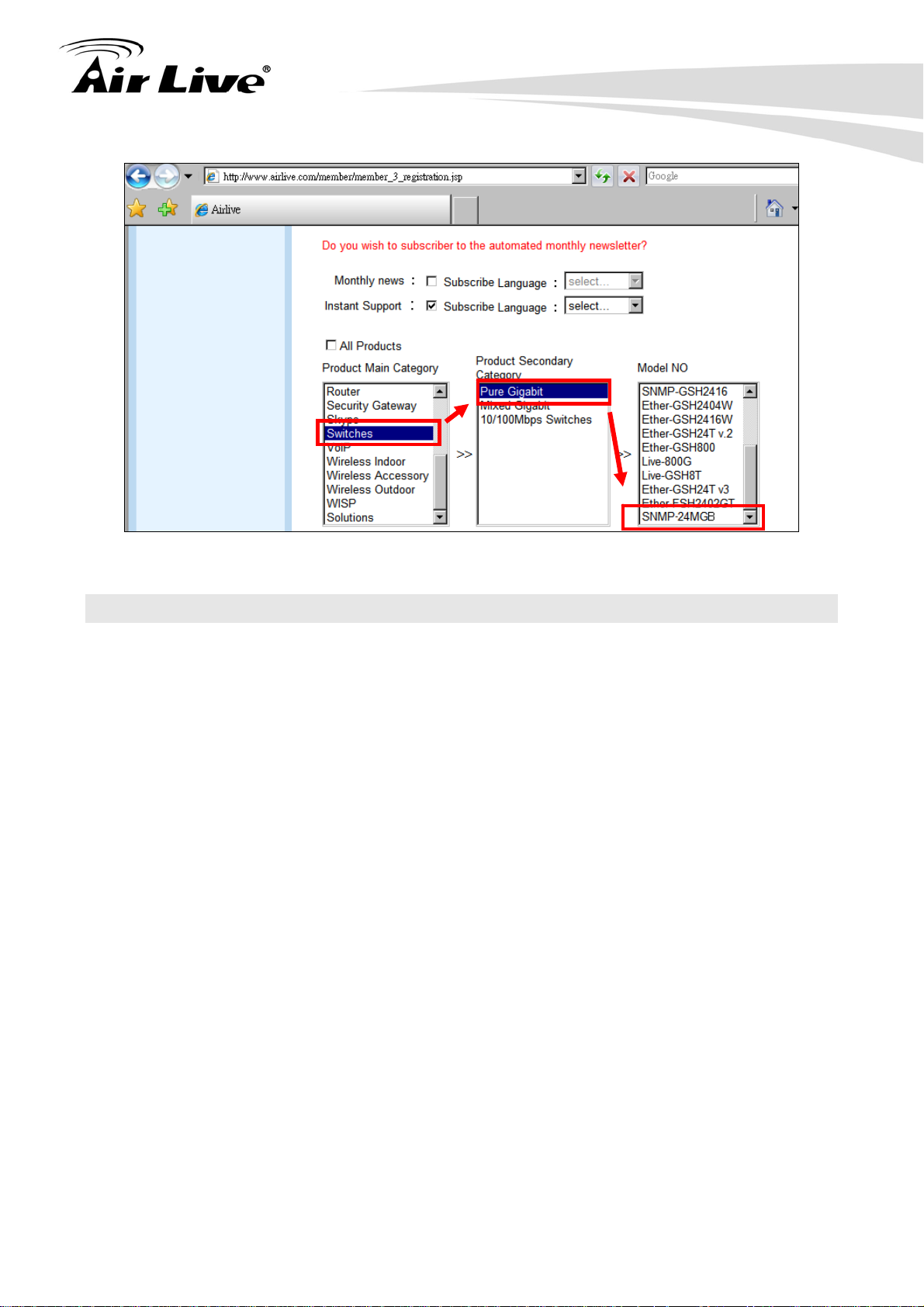
Since 2009, AirLive has added the “Newsletter Instant Support System” on our website.
AirLive Newsletter subscribers receives instant email notifications when there are new
download or tech support FAQ updates for their subscribed airlive models. To become an
AirLive newsletter member, please visit: http://www.airlive.com/member/member_3.jsp
AirLive SNMP-24MGB User’s Manual
2
Page 10
1. Introduction
1.4 Features
Confirms to IEEE802.3 10BASE-T, 802.3u 100BASE-TX, 802.3ab 1000BASE-T,
802.3z Gigabit fiber
16 x Mini-GBIC ports + 8 x 1000Base-T/Mini-GBIC ports (Combo) for Optional Fiber
Connection
High back-plane bandwidth 48Gbps
8K entry MAC address table and 4K VLAN support
Power Saving with "ActiPHY Power Management" and "PerfectReach Power
Management" techniques.
IEEE802.1Q Q-in-Q nested VLAN support
Supports concisely the status of port and easily port configuration
Supports per port traffic monitoring counters
Supports a snapshot of the system Information when you login
Supports port mirror function
Supports the static trunk function
Supports 802.1Q VLAN
Supports user management and limits three users to login
Maximal packet length can be up to 9600 bytes for jumbo frame application
Supports DHCP Broadcasting Suppression to avoid network suspended or crashed
Supports to send the trap event while monitored events happened
3
AirLive SNMP-24MGB User’s Manual
Page 11

1. Introduction
Supports default configuration which can be restored to overwrite the current
configuration which is working on via web browser and CLI
Supports on-line plug/unplug SFP modules
Supports Quality of Service (QoS) for real time applications based on the information
taken from Layer 2 to Layer 4, such as VoIP
Built-in web-based management and CLI management, providing a more convenient UI
for the user
Supports port mirror function with ingress/egress traffic
Supports rapid spanning tree (802.1w RSTP), multiple spanning tree (802.1s MSTP)
Supports 802.1X port security on a VLAN
Supports IP-MAC-Port Binding for LAN security
Supports user management and only first login administrator can configure the device.
The rest of users can only view the switch
SNMP access can be disabled and prevent from illegal SNMP access
Supports Ingress, Non-unicast and Egress Bandwidth rating management with a
resolution of 1Mbps
The trap event and alarm message can be transferred via e-mail
Supports diagnostics to let administrator knowing the hardware status
Supports loop detection to protect the switch crash when the networking has looping
issue
HTTP and TFTP for firmware upgrade, system log upload and configuration file
import/export
Supports remote boot the device through user interface and SNMP
Supports NTP network time synchronization and daylight saving
Supports 120 event log records in the main memory and display on the local console
AirLive SNMP-24MGB User’s Manual
4
Page 12

2. Installing the SNMP-24MGB
2. Installing the
2
This chapter describes the hardware features and the hardware installation procedure for
the SNMP-24MGB. For software configuration, please go to chapter 3 for more details.
SNMP-24MGB
2.2 Before You Start
It is important to read through this section before you install the SNMP-24MGB.
The maximum cabling distance is 100 meters.
Do not create a network loop.
Always check the LED lights for troubleshooting
2.3 Package Content
Unpack the contents of the SNMP-24MGB and verify them against the checklist below.
One unit of SNMP-24MGB
Power Cord
Four Rubber Feet
RS-232 cable
User Guide (CD-ROM)
Quick Installation Guide
Rack-mounted Kit
SNMP-24MGB Power Cord Four Rubber Feet
5
AirLive SNMP-24MGB User’s Manual
Page 13
2. Installing the SNMP-24MGB
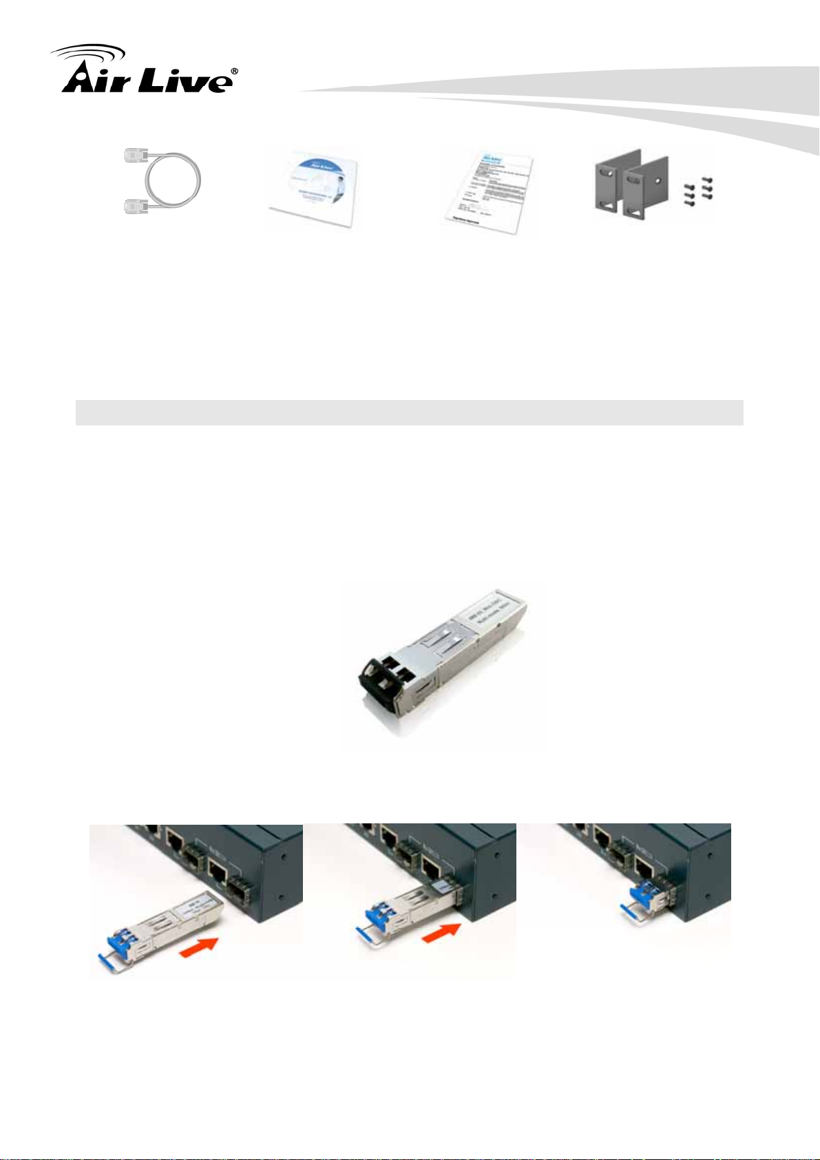
RS-232 cable User Guide (CD-ROM) Quick Installation Guide Rack-mounted Kit
Compare the contents of your SNMP-24MGB package with the standard checklist above. If
any item is missing or damaged, please contact your local dealer for service.
2.4 Optional Accessories
The SNMP-24MGB has the following optional accessories which you can purchase from
AirLive
1000Base-SX MiniGBIC Transceiver (Model: SFP-SX) or 1000Base-LX MiniGBIC
Transceiver (Model: SFP-LX-10) is for your SFP slots of SNMP-24MGB, it allows
you to use fiber cable for extending transmission distance.
Note: While installing MiniGBIC into SFP slot of SNMP-24MGB, please notice the
direction of MiniGBIC is correct, and make sure that MiniGBIC is indeed installed
in the SNMP-24MGB.
AirLive SNMP-24MGB v2 User’s Manual
6
Page 14

2.5 Knowing your SNMP-24MGB
Below are descriptions and diagrams of the product:
2. Installing the SNMP-24MGB
2.6 Hardware Installation
Set the SNMP-24MGB on a sufficiently large flat space with a power outlet nearby. The
surface where you put your SNMP-24MGB should be clean, smooth, level and sturdy.
Make sure there is enough clearance around the SNMP-24MGB to allow attachment of
cables, power cord and allow air circulation.
2.6.1 Attaching Rubber Feet
A. Make sure mounting surface on the bottom of the SNMP-24MGB is grease and dust
free.
B. Remove adhesive backing from your Rubber Feet.
C. Apply the Rubber Feet to each corner on the bottom of the SNMP-24MGB. These
footpads can prevent the Switch from shock/vibration.
7
AirLive SNMP-24MGB User’s Manual
Page 15
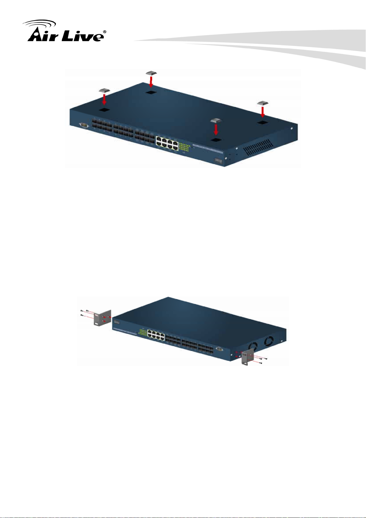
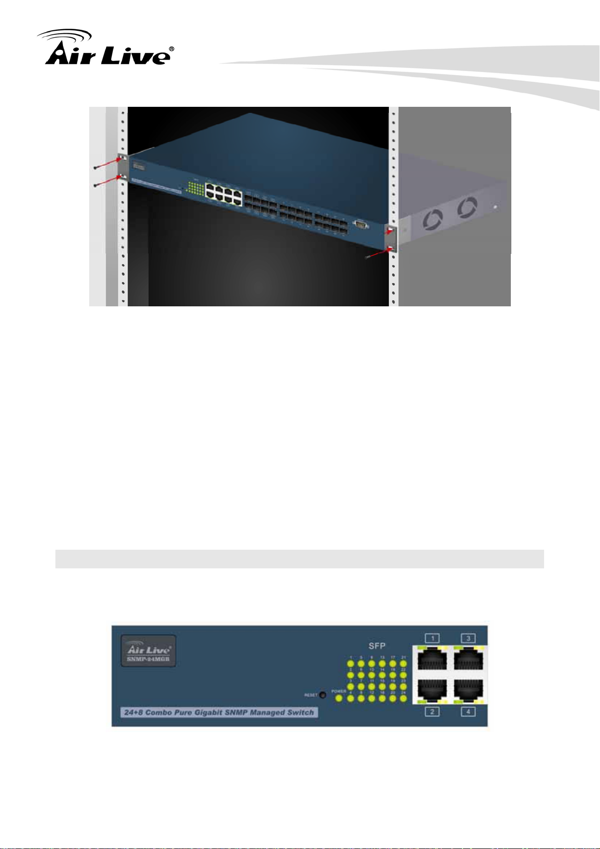
2.6.2 Rack-mounted Installation
2. Installing the SNMP-24MGB
The SNMP-24MGB comes with a rack-mounted kid and can be mounted in an EIA standard
size, 19-inch Rack. The SNMP-24MGB can be placed in a wiring closet with other
equipment. Perform the following steps to rack mount the SNMP-24MGB:
A. Position one bracket to align with the holes on one side of the SNMP-24MGB and
secure it with the smaller bracket screws. Then attach the remaining bracket to the
other side of the SNMP-24MGB.
B. After attached mounting brackets, position the SNMP-24MGB in the rack by lining up
the holes in the brackets with the appropriate holes on the rack. Secure the
SNMP-24MGB to the rack with a screwdriver and the rack-mounting screws.
AirLive SNMP-24MGB v2 User’s Manual
8
Page 16
2. Installing the SNMP-24MGB
Note: For proper ventilation, allow about at least 4 inches (10 cm) of clearance on the
front and 3.4 inches (8 cm) on the back of the Switch. This is especially important for
enclosed rack installation.
2.6.3 Power On
Connect the power cord to the power socket on the rear panel of the SNMP-24MGB. The
other side of power cord connects to the power outlet. The internal power supply of the
SNMP-24MGB works with voltage range of AC in the 100-240VAC, frequency 50~60Hz.
Check the power indicator on the front panel to see if power is properly supplied.
2.7 LED Table
The LED Indicators gives real-time information of systematic operation status. The
following table provides descriptions of LED status and their meaning.
9
AirLive SNMP-24MGB User’s Manual
Page 17
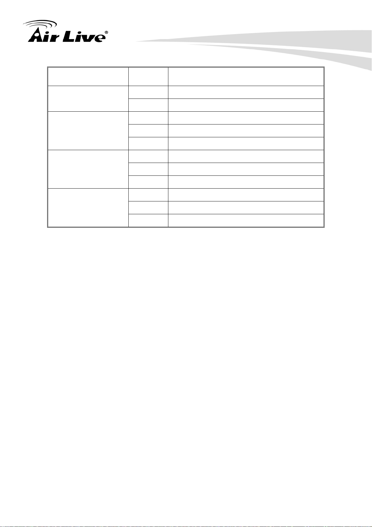
LED Status Description
Green Power On
Power
Off
Green The port is connecting with the device.
Power is not connected
2. Installing the SNMP-24MGB
LNK/ACT
10/100/1000Mbps
SFP(LINK/ACT)
Blink The port is receiving or transmitting data.
Off
No device attached.
Green In 1000Mbps connection speed
Orange In 100Mbps connection speed
Off In half-duplex mode
Green The port is connecting with the device.
Blink The port is receiving or transmitting data.
Off Module connection is not good
AirLive SNMP-24MGB v2 User’s Manual
10
Page 18

3. Configuring the SNMP-24MGB
3. Configuring the
3
The SNMP-24MGB offers many different types of management interface. You can
configure through web browser (http), console (terminal), CLI. In this chapter, we will
explain SNMP-24MGB’s available management interfaces and how to get into them.
Then, we will provide the introduction on Web Management and recommended initial
settings. For detail explanations on Web Management functions, please go to Chapter 4.
For Console interface, please go to Chapter 5.
SNMP-24MGB
3.1 Important Information
The following information will help you to get start quickly. However, we recommend you
to read through the entire manual before you start. Please note the username and
password are case sensitive.
The default IP address is 192.168.1.1
The default Subnet Mask is 255.255.255.0
The default Gateway is 192.168.1.254
The default username is admin
The default password is airlive
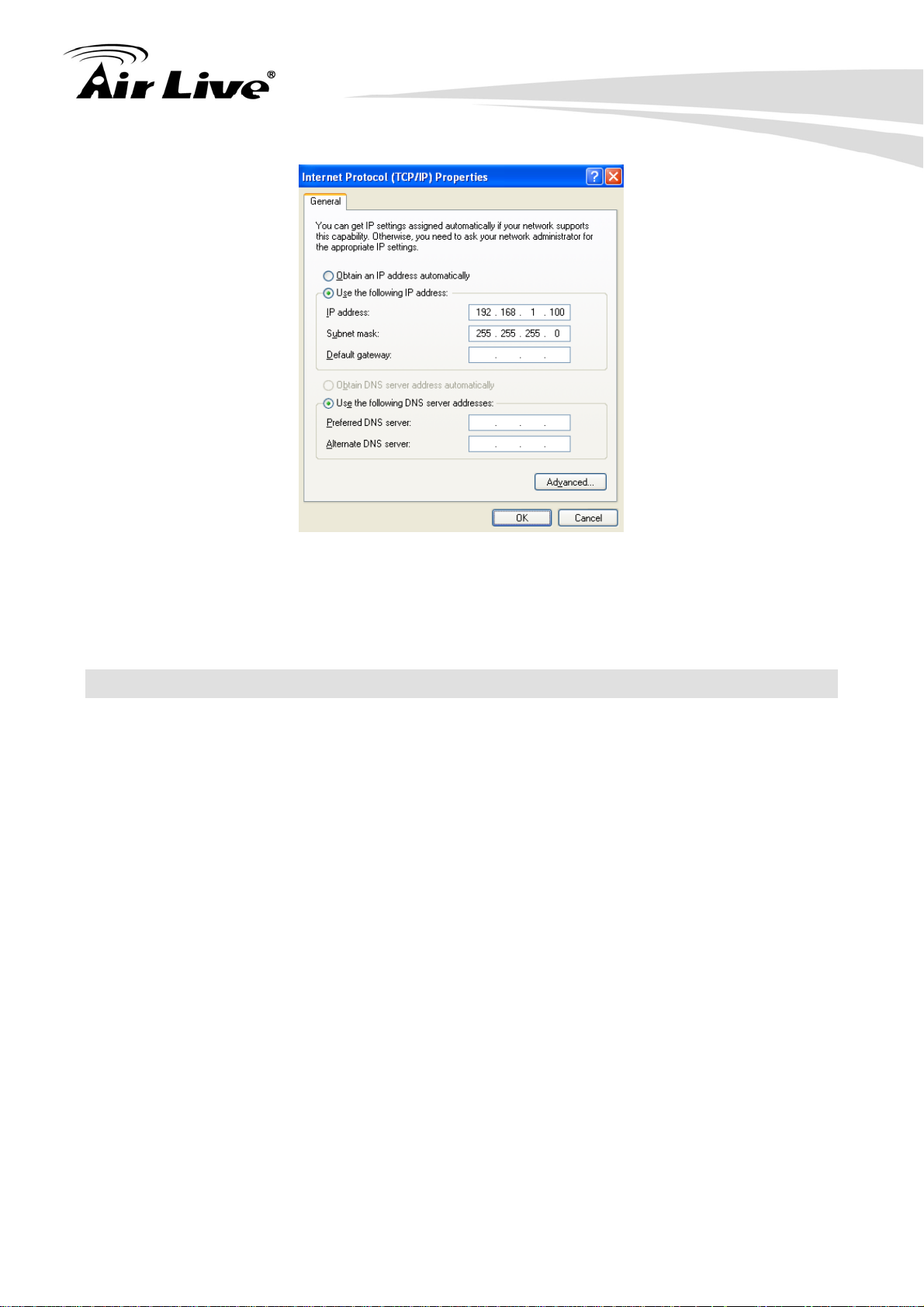
3.2 Prepare your PC
The SNMP-24MGB can be managed remotely by a PC through RJ-45 cable. The default
IP address of the SNMP-24MGB is 192.168.1.1 with a subnet mask of 255.255.255.0.
This means the IP address of the PC should be in the range of 192.168.1.2 to
192.168.1.253.
To prepare your PC for management with the SNMP-24MGB, please do the following:
1. Connect your PC directly to the copper port of SNMP-24MGB
2. Set your PC’s IP address manually to 192.168.1.100 (or other address in the same
subnet)
11
AirLive SNMP-24MGB User’s Manual
Page 19
3. Configuring the SNMP-24MGB
You are ready now to configure the SNMP-24MGB by using your PC.
3.3 Management Interface
The SNMP-24MGB can be configured using on the management interfaces below:
Web Management (HTTP): You can manage your SNMP-24MGB by simply typing its
IP address in the web browser. Most functions of SNMP-24MGB can be accessed by
web management inter face. We recommend using this interface for initial
configurations. To begin, simply enter SNMP-24MGB’s IP address (default is
192.168.1.1) on the web browser. The default username is admin and password is
airlive.
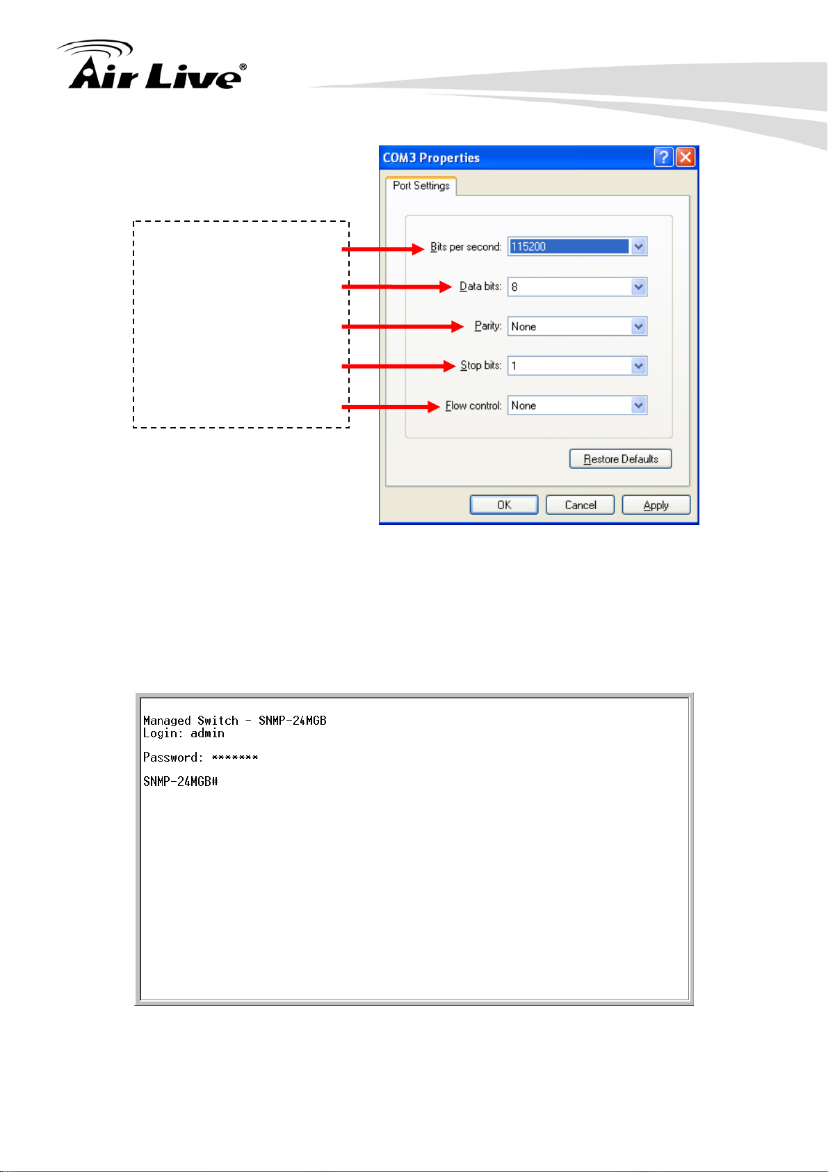
Console Management (Terminal): SNMP-24MGB can be managed through terminal
emulation program or Hyper Terminal.
When the connection between SNMP-24MGB and PC is ready, turn on the PC and run
a terminal emulation program or Hyper Terminal and configure its communication
parameters to match the following default characteristics of the console port
AirLive SNMP-24MGB v2 User’s Manual
12
Page 20
3. Configuring the SNMP-24MGB
Baud Rate: 115200 bps
Data Bits: 8
Parity: none
Stop Bit: 1
Flow control: None
After finishing the parameter settings, click “OK“. When the blank screen shows up,
press Enter key to bring out the login prompt. Key in the “admin“(default value) for the
User name and “airlive” for the Password (use Enter key to switch), then press Enter
key and the Main Menu of console management appears. Please see below figure for
login screen.
Telnet Management (Terminal): SNMP-24MGB can be managed through telnet. To
13
AirLive SNMP-24MGB User’s Manual
Page 21
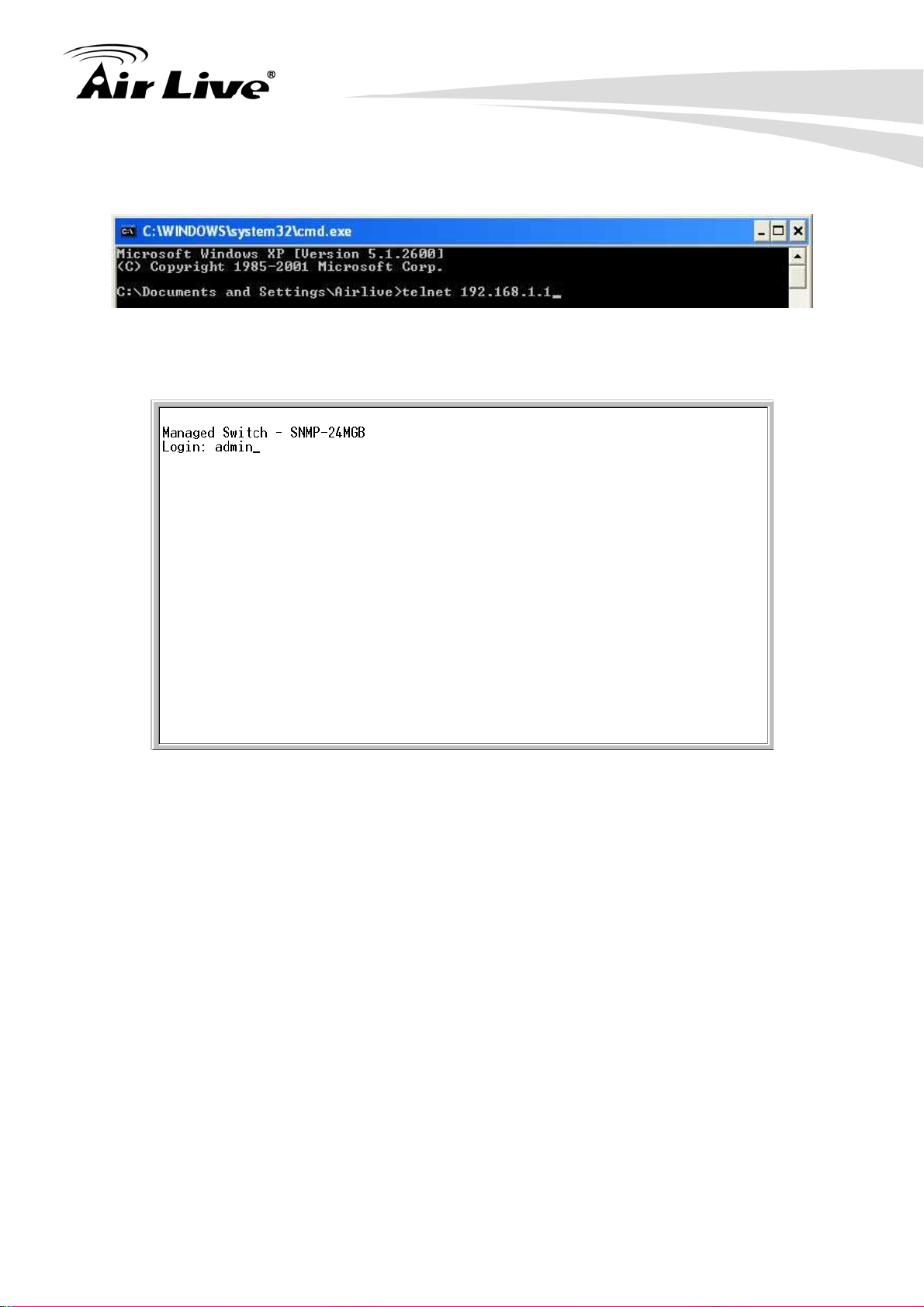
3. Configuring the SNMP-24MGB
use the telnet, please open the command line windows. Then type “telnet 192.168.1.1”
to start.
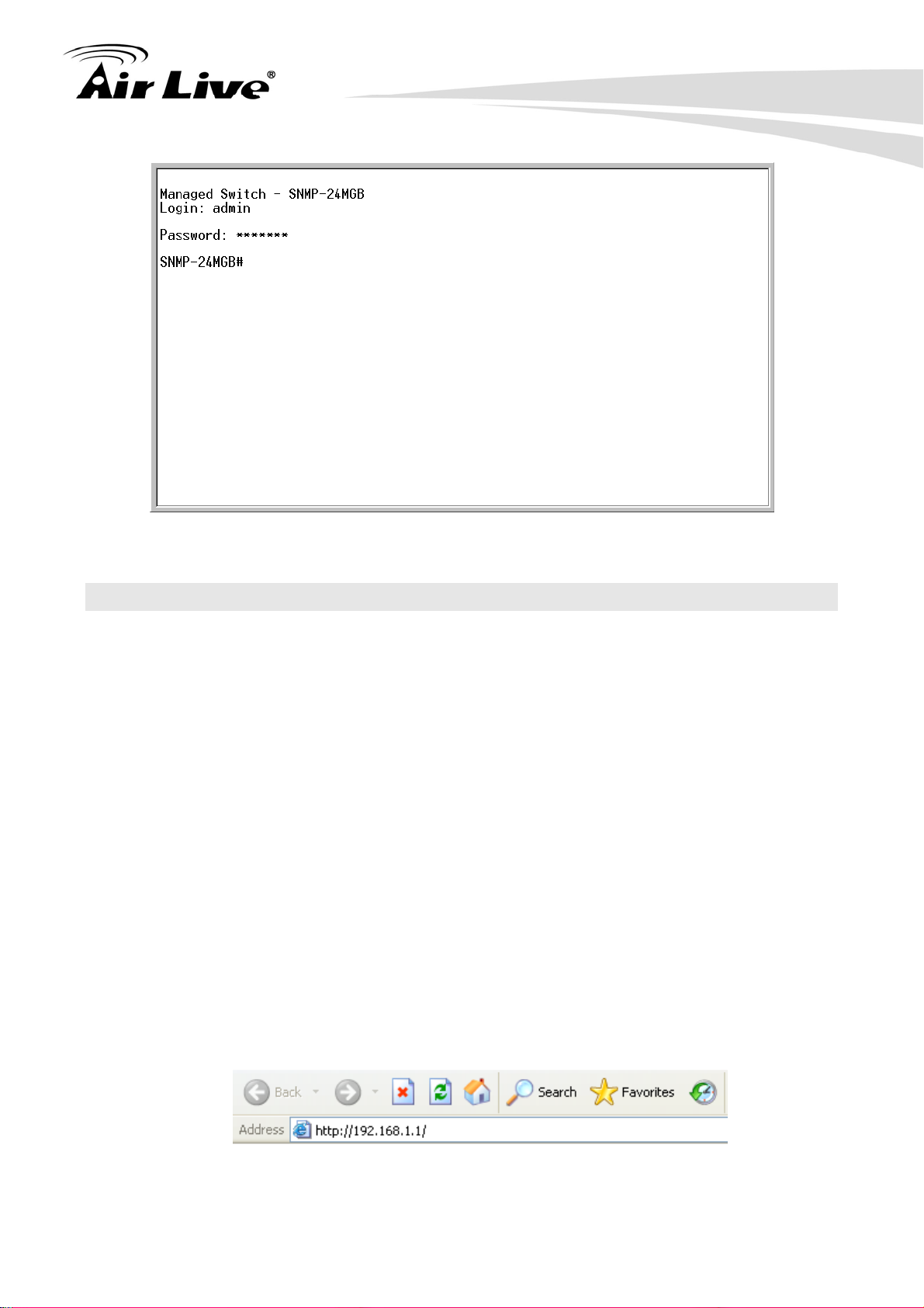
When asking for username and password, please enter “admin” as username and “airlive”
as password.
After you login successfully, the prompt will be shown as “#“ if you are the first login person
and your authorization is administrator; otherwise it may show “$“. See the following two
figures. The former means you behave as an administrator and have the access right of the
system. As to the latter, it means you behave as a guest and are only allowed to view the
system without the permission to do any setting for this switch.
AirLive SNMP-24MGB v2 User’s Manual
14
Page 22
3. Configuring the SNMP-24MGB
3.4 Introduction to Web Management
The SNMP-24MGB offers Web Management interfaces for users. Users can easily
access and control SNMP-24MGB via web browsers. The Web-Based Management
supports Internet Explorer 5.0. It is based on Java Applets with an aim to reduce network
bandwidth consumption, enhance access speed and present an easy viewing screen.
Note: By default, IE5.0 or later version does not allow Java Applets to open sockets. The
user has to explicitly modify the browser setting to enable Java Applets to use network
ports.
3.4.1 Getting into Web Management
Web Management (HTTP)
1. Launch the Internet Explorer.
2. Type http://192.168.1.1. Press “Enter”.
15
AirLive SNMP-24MGB User’s Manual
Page 23
3. Configuring the SNMP-24MGB
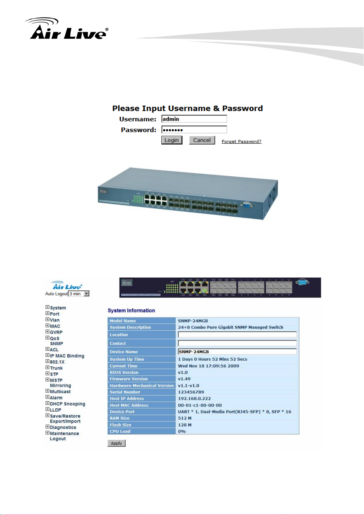
3. The login screen appears.
4. Key in the user name and password. The default user name is “admin” and password
is “airlive”.
5. Click “Enter” or ”Login”, then the home screen of the Web-based management
appears.
AirLive SNMP-24MGB v2 User’s Manual
16
Page 24
4. Web Management in SNMP-24MGB
4. Web Management in
4
In this chapter, we will explain all settings in web management interface. Please be sure
to read through Chapter 3’s “Introduction to Web Management” first.
SNMP-24MGB
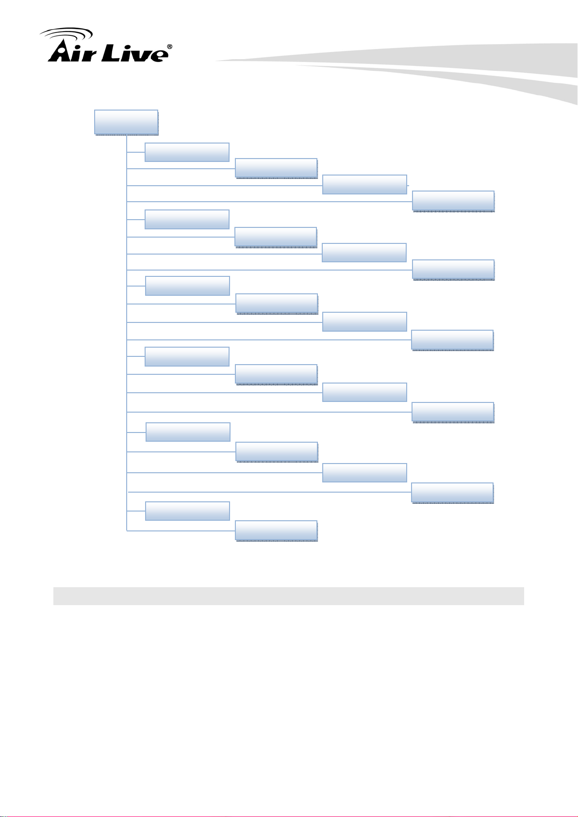
4.1 Menu Structure of SNMP-24MGB
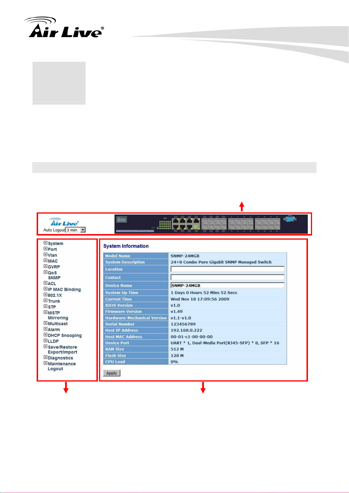
The web management menu of SNMP-24MGB is divided into 3 parts: Top Bar, Side Menu
Bar, and Main Screen.
Top Bar
Side Menu
Top Bar: It display panel GUI. You can direct click the port on the Switch figure
on the top of web page. Then, you will see the port information. On the left-top
corner, there is a pull-down list for Auto Logout. For the sake of security, we provide
auto-logout function to protect you from illegal user as you are leaving. If you do not
choose any selection in Auto Logout list, it means you turn on the Auto Logout
Main Screen
17
AirLive SNMP-24MGB User’s Manual
Page 25

4. Web Management in SNMP-24MGB
function and the system will be logged out automatically when no action on the
device 3 minutes later. If OFF is chosen, the screen will keep as it is. Default is ON.
Side Menu: All management functions will show in Side Menu, you can choose any
one of them to configure its setting. The detailed introduction for all management
function will explain in below chapters. The following list is the full function tree for
web user interface.
Main Screen: Once choosing any function of Side Menu, the configuration page of
the function will show in Main Screen. You can configure the function by instruction
of manual.
AirLive SNMP-24MGB v2 User’s Manual
18
Page 26
4. Web Management in SNMP-24MGB
A
g
A
Root
System
Port
VLAN
MAC
GVRP
QoS
SNMP
CL
IP MAC Binding
802.1X
Trunk
STP
MSTP
Mirrorin
Multicast
larm
DHCP
Save/Restore
Maintenance
4.2 System
4.2.1 IP Configuration
Function name:
System Information
Function description:
Export/Imports
Diagnostics
Logout
19
AirLive SNMP-24MGB User’s Manual
Page 27

Show the basic system information.
4. Web Management in SNMP-24MGB
Parameter description:
Model name:
The product name of this device.
System description:
The product description of this device.
Location:
Basically, it is the location where this switch is put. It can be defined by user.
Contact:
For easily managing and maintaining device, you may write down the contact
person and phone here for getting help soon. You can configure this parameter
through the device’s user interface or SNMP.
Device name:
The name of the switch. It can be defined by user. Default is SNMP-24MGB.
System up time:
The time accumulated since this switch is powered up. Its format is day, hour,
minute, second.
AirLive SNMP-24MGB v2 User’s Manual
20
Page 28

Current time:
Show the system time of the switch. Its format is day of week, month, day, hours :
minutes : seconds, year. For instance, Mon, March. 03, 14:54:07, 2008.
BIOS version:
The version of the BIOS in this switch.
Firmware version:
The firmware version in this switch.
Hardware-Mechanical version:
The version of Hardware and Mechanical. The figure before the hyphen is the
version of electronic hardware; the one after the hyphen is the version of
mechanical.
4. Web Management in SNMP-24MGB
Serial number:
The serial number is assigned by the manufacturer.
Host IP address:
The IP address of the switch.
Host MAC address:
It is the Ethernet MAC address of the management agent in this switch.
Device Port:
Show all types and numbers of the port in the switch.
RAM size:
The size of the DRAM in this switch.
Flash size:
The size of the flash memory in this switch.
CPU Load:
To display the CPU loading percent on this switch.
4.2.2 Account Configuration
In this function, only administrator can create, modify or delete the username and password.
Administrator can modify other guest identities’ password without confirming the password
but it is necessary to modify the administrator-equivalent identity. Guest-equivalent identity
can modify his password only. Please note that you must confirm administrator/guest
identity in the field of Authorization in advance before configuring the username and
password. Only one administrator is allowed to exist and unable to be deleted. In addition,
21
AirLive SNMP-24MGB User’s Manual
Page 29
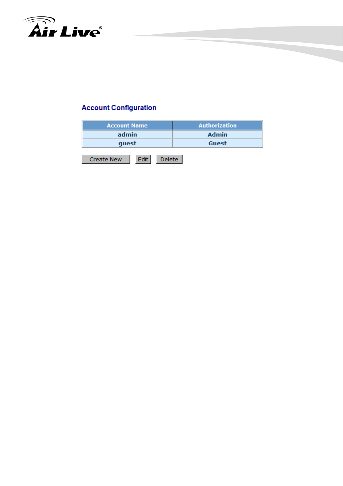
up to 4 guest accounts can be created.
The default setting for user account is:
Username: admin Password: airlive
4. Web Management in SNMP-24MGB
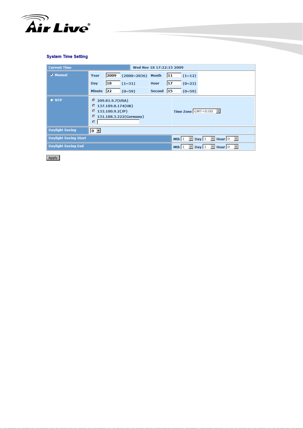
4.2.3 Time Configuration
The switch provides manual and automatic ways to set the system time via NTP. Manual
setting is simple and you just input “Year”, “Month”, “Day”, “Hour”, “Minute” and “Second”
within the valid value range indicated in each item. If you input an invalid value, for example,
61 in minute, the switch will clamp the figure to 59.
NTP is a well-known protocol used to synchronize the clock of the switch system time over
a network. NTP, an internet draft standard formalized in RFC 1305, has been adopted on
the system is version 3 protocol. The switch provides four built-in NTP server IP addresses
resided in the Internet and a user-defined NTP server IP address. The time zone is
Greenwich-centered which uses the expression form of GMT+/- xx hours.
Function name:
Time
Function description:
Set the system time by manual input or set it by syncing from Time servers. The
function also supports daylight saving for different area’s time adjustment.
AirLive SNMP-24MGB v2 User’s Manual
22
Page 30
4. Web Management in SNMP-24MGB
Parameter description:
Current Time:
Show the current time of the system.
Manual:
This is the function to adjust the time manually. Filling the valid figures in the fields
of Year, Month, Day, Hour, Minute and Second respectively and press <Apply>
button, time is adjusted. The valid figures for the parameter Year, Month, Day,
Hour, Minute and Second are >=2000, 1-12, 1-31, 0-23, 0-59 and 0-59
respectively. Input the wrong figure and press <Apply> button, the device will
reject the time adjustment request. There is no time zone setting in Manual mode.
Default: Year = 2000; Month = 1; Day = 1; Hour = 0, Minute = 0; Second = 0
NTP:
NTP is Network Time Protocol and is used to sync the network time based
Greenwich Mean Time (GMT). If use the NTP mode and select a built-in NTP time
server or manually specify an user-defined NTP server as well as Time Zone, the
switch will sync the time in a short after pressing <Apply> button. Though it
synchronizes the time automatically, NTP does not update the time periodically
without user’s processing.
Time Zone is an offset time off GMT. You have to select the time zone first and
then perform time sync via NTP because the switch will combine this time zone
offset and updated NTP time to come out the local time, otherwise, you will not
able to get the correct time. The switch supports configurable time zone from –12
to +13 step 1 hour.
Default Time zone: +8 Hrs.
Daylight Saving:
23
AirLive SNMP-24MGB User’s Manual
Page 31

4. Web Management in SNMP-24MGB
Daylight saving is adopted in some countries. If set, it will adjust the time lag or in
advance in unit of hours, according to the starting date and the ending date. For
example, if you set the day light saving to be 1 hour. When the time passes over
the starting time, the system time will be increased one hour after one minute at
the time since it passed over. And when the time passes over the ending time, the
system time will be decreased one hour after one minute at the time since it
passed over.
The switch supports valid configurable day light saving time is –5 ~ +5 step one
hour. The zero for this parameter means it need not have to adjust current time,
equivalent to in-act daylight saving. You don’t have to set the starting/ending date
as well. If you set daylight saving to be non-zero, you have to set the
starting/ending date as well; otherwise, the daylight saving function will not be
activated.
Default for Daylight Saving: 0.
The following parameters are configurable for the function Daylight Saving and
described in detail.
Day Light Saving Start :
This is used to set when to start performing the day light saving time.
Mth: Range is 1 ~ 12; Default: 1
Day: Range is 1 ~ 31; Default: 1
Hour: Range is 0 ~ 23; Default: 0
Day Light Saving End :
This is used to set when to stop performing the daylight saving time.
Mth: Range is 1 ~ 12; Default: 1
Day: Range is 1 ~ 31; Default: 1
Hour: Range is 0 ~ 23; Default: 0
4.2.4 IP Configuration
It is one of the most important configurations in the switch. Without the proper setting,
network manager will not be able to manage or view the device. The switch supports both
manual IP address setting and automatic IP address setting via DHCP server. When IP
address is changed, you must reboot the switch to have the setting taken effect and use the
new IP to browse for web management and CLI management.
Function name:
AirLive SNMP-24MGB v2 User’s Manual
24
Page 32

4. Web Management in SNMP-24MGB
IP Configuration
Function description:
Set IP address, subnet mask, default gateway and DNS for the switch.
Parameter description:
DHCP Setting:
The switch supports DHCP client used to get an IP address automatically if you
set this function “Enable”. When enabled, the switch will issue the request to the
DHCP server resided in the network to get an IP address. If DHCP server is down
or does not exist, the switch will issue the request and show IP address is under
requesting, until the DHCP server is up. Before getting an IP address from DHCP
server, the device will not continue booting procedures. If set this field “Disable”,
you’ll have to input IP address manually. For more details about IP address and
DHCP, please see the Section 2-1-5 “IP Address Assignment” in this manual.
Default: Disable
25
AirLive SNMP-24MGB User’s Manual
Page 33

IP address:
Users can configure the IP settings and fill in new values if users set the DHCP
function “Disable”. Then, click <Apply> button to update. When DHCP is
disabled, Default: 192.168.1.1
If DHCP is enabled, this field is filled by DHCP server and will not allow user
manually set it any more.
Subnet mask:
Subnet mask is made for the purpose to get more network address because any
IP device in a network must own its IP address, composed of Network address
and Host address, otherwise can’t communicate with other devices each other.
But unfortunately, the network classes A, B, and C are all too large to fit for almost
all networks, hence, subnet mask is introduced to solve this problem. Subnet
mask uses some bits from host address and makes an IP address looked Network
address, Subnet mask number and host address. It is shown in the following figure.
This reduces the total IP number of a network able to support, by the amount of 2
power of the bit number of subnet number (2^(bit number of subnet number)).
4. Web Management in SNMP-24MGB
Network ID
32 bits
Host ID
Network ID Host ID
Subnet number
Subnet mask is used to set the subnet mask value, which should be the same
value as that of the other devices resided in the same network it attaches. Default:
255.255.255.0
Default gateway:
Set an IP address for a gateway to handle those packets that do not meet the
routing rules predefined in the device. If a packet does not meet the criteria for
other pre-defined path, it must be forwarded to a default router on a default path.
This means any packet with undefined IP address in the routing table will be sent
to this device unconditionally. Default: 192.168.1.254
AirLive SNMP-24MGB v2 User’s Manual
26
Page 34

4. Web Management in SNMP-24MGB
DNS:
It is Domain Name Server used to serve the translation between IP address and
name address.
The switch supports DNS client function to re-route the mnemonic name address
to DNS server to get its associated IP address for accessing Internet. User can
specify a DNS IP address for the switch. With this, the switch can translate a
mnemonic name address into an IP address.
There are two ways to specify the IP address of DNS. One is fixed mode, which
manually specifies its IP address, the other is dynamic mode, which is assigned by
DHCP server while DHCP is enabled. DNS can help you easily remember the
mnemonic address name with the meaningful words in it. Default is no assignment
of DNS address. Default: 0.0.0.0
4.2.5 Loop Detection
Loop detection is used to detect the presence of traffic. When switch receives packet’s
(looping detection frame) MAC address the same as oneself from port, show Loop
detection happens. The port will be locked when it received the looping detection frames. If
you want to resume the locked port, please find out the looping path and take off the
looping path, then select the resume the locked port and click on “Resume” to turn on the
locked ports.
Function name:
Loop Detection
Function description:
Display whether switch open Loop detection.
27
AirLive SNMP-24MGB User’s Manual
Page 35

4. Web Management in SNMP-24MGB
Parameter description:
Port No:
Display the port number. The number is 1 – 24.
Detection Port - Enable:
When Port No. is chosen, and enable port's Loop detection, the port can detect
loop happens. When loop happen, port will be locked. If loop did not happen,
port maintains Unlocked.
Locked Port - Resume:
When choosing Resume, locked port will be opened and turned into unlocked. If
not choosing Resume, Port maintains locked.
4.2.6 Management Policy
Through the management security configuration, the manager can do the strict setup to
control the switch and limit the user to access this switch.
The following rules are offered for the manager to manage the switch:
AirLive SNMP-24MGB v2 User’s Manual
28
Page 36

4. Web Management in SNMP-24MGB
Rule 1:
Rule 2:
Rule 3:
Rule 4
Rule 5
When no list exists, then it will accept all connections.
Accept
When only “accept lists” exist, then it will deny all connections,
excluding the connection inside of the accepting range.
Accept
Deny
When only “deny lists” exist, then it will accept all connections,
excluding the connection inside of the denying range.
Deny
Accept
When both “accept and deny” lists exist, then it will deny all
connections, excluding the connection inside of the accepting range.
Accept Deny
Deny
When both “accept and deny” lists exist, then it will deny all
connections, excluding the connection inside of the accepting range
and NOT inside of the denying range at the same time.
Accept
Deny
Accept
Deny
Function name:
Management Security Configuration
Function description:
The switch offers Management Security Configuration function. With this function, the
manager can easily control the mode that the user connects to the switch. According to
29
AirLive SNMP-24MGB User’s Manual
Page 37

4. Web Management in SNMP-24MGB
the mode, users can be classified into two types: Those who are able to connect to the
switch (Accept) and those who are unable to connect to the switch (Deny). Some
restrictions also can be placed on the mode that the user connect to the switch, for
example, we can decide that which VLAN VID is able to be accepted or denied by the
switch, the IP range of the user could be accepted or denied by the switch, the port that
the user is allowed or not allowed to connect with the switch, or the way of controlling
and connecting to the switch via Http, Telnet or SNMP.
Add:
A new entry of Management Security Configuration can be created after the
parameters as mentioned above had been setup and then press <Add> button.
The existed entry also can be modified by pressing this button.
Delete:
Remove the existed entry of Management Security Configuration from the
management security table.
Name:
A name is composed of any letter (A-Z, a-z) and digit (0-9) with maximal 8
characters.
IP Range:
The switch supports two kinds of options for managed valid IP Range, including
“Any” and “Custom”. Default is “Any”. In case that ”Custom” is chosen, you can
assigned effective IP range. The valid range is 0.0.0.0~255.255.255.255.
AirLive SNMP-24MGB v2 User’s Manual
30
Page 38

Incoming Port:
The switch supports two kinds of options for managed valid Port Range, including
“Any” and “Custom”. Default is “Any”. You can select the ports that you would like
them to be worked and restricted in the management security configuration
if ”Custom” had been chosen.
Access Type:
The switch supports two kinds of options for managed valid Access Type,
including “Any” and “Custom”. Default is “Any”. “Http”, “Telnet” and “SNMP” are
three ways for the access and managing the switch in case that” Custom” had
been chosen.
Action:
The switch supports two kinds of options for managed valid Action Type, including
“Deny” and “Accept”. Default is “Deny”. When you choose “Deny” action, you will
be restricted and refused to manage the switch due to the “Access Type” you
choose. However, while you select “Accept” action, you will have the authority to
manage the switch.
4. Web Management in SNMP-24MGB
4.2.7 System Log
The System Log provides information about system logs, including information when the
device was booted, how the ports are operating, when users logged in, when sessions
timed out, as well as other system information.
Function name:
System log
Function description:
The Trap Log Data is displaying the log items including all SNMP Private Trap events,
SNMP Public traps and user logs occurred in the system. In the report table, No., Time
and Events are three fields contained in each trap record.
31
AirLive SNMP-24MGB User’s Manual
Page 39

Parameter description:
No:
Display the order number that the trap happened.
4. Web Management in SNMP-24MGB
Time:
Display the time that the trap happened.
Desc:
Display a description event recorded in the System Log.
Clear:
Clear log data.
4.2.8 Virtual Stack
Function name:
Virtual Stack
Function description:
Virtual Stack Management (VSM) is the group management function. Through the
proper configuration of this function, switches in the same LAN will be grouped
automatically. And among these switch, one switch will be a master machine, and the
others in this group will become slave devices.
VSM offers a simple centralized management function. It is not necessary to
remember the address of all devices, manager is capable of managing the network
with knowing the address of the Master machine. Instead of SNMP or Telnet UI, VSM
is only available in Web UI. While one switch becomes the Master, two rows of buttons
for group device will appear on the top of its Web UI. By pressing these buttons, user
will be allowed to connect the Web UI of the devices of the group in the same window
without the login of these devices.
AirLive SNMP-24MGB v2 User’s Manual
32
Page 40

4. Web Management in SNMP-24MGB
The most top-left button is only for Master device. The background color of the button
you press will be changed to represent that the device is under your management.
Note: It will remove the grouping temporarily in case that you login the switch via the
console.
The devices of the group will be shown as station address (the last number of IP
Address) + device name on the button (e.g. 196_SBMP-24MGB), otherwise it will
show ” ---- “ if no corresponding device exists.
Once the devices join the group successfully, then they are merely able to be managed
via Master device, and user will fail to manage them via telnet/console/web individually.
Up to 16 devices can be grouped for VSM, however, only one Master is allowed to
exist in each group. For Master redundancy, user may configure more than two
devices as Master device, however, the Master device with the smaller MAC value will
be the Master one. All of these 16 devices can become Master device and back up
with each other.
Parameter description:
State:
It is used for the activation or de-activation of VSM. Default is Enable.
Role:
The role that the Switch would like to play in virtual stack. Two types of roles,
including master and slave are offered for option. Default is Master.
Group ID:
It is the group identifier (GID) which signs for VSM. Valid letters are A-Z, a-z, 0-9,
“ - “ and “_” characters. The maximal length is 15 characters.
33
AirLive SNMP-24MGB User’s Manual
Page 41

4. Web Management in SNMP-24MGB
4.3 Port
Port Configuration, Port Status, Simple Counter and Detail Counter are contained in
this function folder for port monitor and management. Each of them will be described in
detail orderly in the following sections.
Port Configuration
Configuration
Status
Simple Counter
Detail Counter
4.3.1 Port Configuration
Port Configuration is applied to change the setting of each port. In this configuration
function, you can set/reset the following functions. All of them are described in detail
below.
Function name:
Port Configuration
Function description:
It is used to set each port’s operation mode. The switch supports 3 parameters for
each port. They are state, mode and flow control.
AirLive SNMP-24MGB v2 User’s Manual
34
Page 42

4. Web Management in SNMP-24MGB
Parameter description:
Port:
To display the port index
Media:
To display the port media type with UTP or SFP
Speed:
Set the speed and duplex of the port. In speed, if the media is 1Gbps fiber, it is
always 1000Mbps and the duplex is full only. If the media is TP, the Speed/Duplex
is comprised of the combination of speed mode, 10/100/1000Mbps, and duplex
mode, full duplex and half duplex. The following table summarized the function the
35
AirLive SNMP-24MGB User’s Manual
Page 43

media supports.
In Auto-negotiation mode, no default value. In Forced mode, default value
depends on your setting.
Flow Control:
There are two modes to choose in flow control, including Enable and Disable. If
flow control is set Enable, both parties can send PAUSE frame to the transmitting
device(s) if the receiving port is too busy to handle. When it is set Disable, there
will be no flow control in the port. It drops the packet if too much to handle.
4. Web Management in SNMP-24MGB
Media type NWay Speed Duplex
1000M TP ON/OFF 10/100/1000M Full for all, Half for 10/100
1000M Fiber ON/OFF 1000M Full
Maximum Frame:
This module offers 1518~9600 (Bytes) packet length to make the long packet.
Excessive Collision Mode:
There are two modes to choose when excessive collision happens in half-duplex
condition as below:
Discard: The “Discard” mode determines whether the MAC drop frames after an
excessive collision has occurred. If set, a frame is dropped after excessive
collisions. This is IEEE 802.3 half-duplex flow control operation.
Restart: The “Restart” mode determines whether the MAC retransmits frames
after an excessive collision has occurred. If set, a frame is not dropped after
excessive collisions, but the backoff sequence is restarted. This is a violation of
IEEE 802.3, but is useful in non-dropping half-duplex flow control operation.
Description:
Description of device ports can not include “ # % & ‘ + \.
4.3.2 Port Status
The function gathers the information of all ports’ current status and reports it by the order of
port number, media, link status, port state, Auto-Negotiation status, speed/duplex, Rx
Pause and Tx Pause. An extra media type information for the module ports 1 and 8 is also
offered.
AirLive SNMP-24MGB v2 User’s Manual
36
Page 44

4. Web Management in SNMP-24MGB
Function name:
Port Status
Function Description:
Report the latest updated status of all ports in this switch. When any one of the ports in
the switch changes its parameter displayed in the page, it will be automatically
refreshed the port current status about every 5 seconds.
37
AirLive SNMP-24MGB User’s Manual
Page 45

Parameter Description:
Port:
Display the port number. The number is 1 – 24.
Link:
Show that if the link on the port is active or not. If the link is connected to a
working-well device, the Link will show the link “Up”; otherwise, it will show “Down”.
This is determined by the hardware on both devices of the connection. No default
value.
Speed / Duplex Mode:
Display the speed and duplex of all port. There are three speeds 10Mbps,
100Mbps and 1000Mbps supported for TP media, and the duplex supported is half
duplex and full duplex. If the media is 1Gbps fiber, it is 1000Mbps supported only.
The status of speed/duplex mode is determined by 1) the negotiation of both local
port and link partner in “Auto Speed” mode or 2) user setting in “Force” mode. The
local port has to be preset its capability. Default is None, depends on the result of
the negotiation.
4. Web Management in SNMP-24MGB
Flow Control:
Show each port’s flow control status.
There are two types of flow control in Ethernet, Backpressure for half-duplex
operation and Pause flow control (IEEE802.3x) for full-duplex operation. The
switch supports both of them. Default is None, depends on the result of the
negotiation.
Description:
Network managers provide a description of device ports.
AirLive SNMP-24MGB v2 User’s Manual
38
Page 46

Parameter description of Port 1 ~ Port 24:
Connector Type:
Display the connector type, for instance, UTP, SC, ST, LC and so on.
Fiber Type:
Display the fiber mode, for instance, Multi-Mode, Single-Mode.
Tx Central Wavelength:
Display the fiber optical transmitting central wavelength, for instance, 850nm,
1310nm, 1550nm and so on.
Baud Rate:
Display the maximum baud rate of the fiber module supported, for instance,
10M, 100M, 1G and so on.
4. Web Management in SNMP-24MGB
Vendor OUI:
Display the Manufacturer's OUI code which is assigned by IEEE.
Vendor Name:
Display the company name of the module manufacturer.
Vendor P/N:
Display the product name of the naming by module manufacturer.
Vendor Rev (Revision):
Display the module revision.
Vendor SN (Serial Number):
Show the serial number assigned by the manufacturer.
Date Code:
Show the date this SFP module was made.
Temperature:
Show the current temperature of SFP module.
Vcc:
Show the working DC voltage of SFP module.
Mon1(Bias) mA:
Show the Bias current of SFP module.
Mon2(TX PWR):
Show the transmit power of SFP module.
Mon3(RX PWR):
Show the receiver power of SFP module.
39
AirLive SNMP-24MGB User’s Manual
Page 47

4. Web Management in SNMP-24MGB
4.3.3 Simple Counter
The function of Simple Counter collects any information and provides the counting about
the traffic of the port, no matter the packet is good or bad.
In below figure, the window can show all ports’ counter information at the same time. Each
data field has 20-digit long. If the counting is overflow, the counter will be reset and restart
counting. The data is updated every time interval defined by the user. The Refresh Interval
is used to set the update frequency.
Function name:
Simple Counter
Function description:
Display the summary counting of each port’s traffic, including Tx Byte, Rx Byte, Tx
Packet, Rx Packet, Tx Collision and Rx Error Packet.
AirLive SNMP-24MGB v2 User’s Manual
40
Page 48

Parameters description:
Packet:
Transmit:
The counting number of the packet transmitted.
Receive:
The counting number of the packet received.
Bytes:
Transmit:
Total transmitted bytes.
4. Web Management in SNMP-24MGB
Receive:
Total received bytes.
Error:
Transmit:
Number of bad packets transmitted.
Receive:
Number of bad packets received.
Drops:
Transmit:
Number of packets transmitted drop.
Receive:
Number of packets received drop.
Auto-refresh:
The simple counts will be refreshed automatically on the UI screen.
Refresh:
The simple counts will be refreshed manually when user use mouse to click on
“Refresh” button.
Clear:
The simple counts will be reset to zero when user use mouse to click on “Clear”
button.
41
AirLive SNMP-24MGB User’s Manual
Page 49

4. Web Management in SNMP-24MGB
4.3.4 Detail Counter
The function of Detail Counter collects any information and provides the counting about the
traffic of the port, no matter the packet is good or bad.
In below figure, the window can show only one port counter information at the same time.
To see another port’s counter, you have to pull down the list of Select, then you will see the
figures displayed about the port you had chosen.
Each data field has 20-digit long. If the counting is overflow, the counter will be reset and
restart counting. The data is updated every time interval defined by the user. The valid
range is 3 to 10 seconds. The Refresh Interval is used to set the update frequency. Default
update time is 3 seconds.
Function name:
Detail Counter
Function description:
Display the detailed counting number of each port’s traffic. The window can show all
counter information of each port at one time.
Parameter description:
Rx Packets:
The counting number of the packet received.
RX Octets:
Total received bytes.
AirLive SNMP-24MGB v2 User’s Manual
42
Page 50

Rx High Priority Packets:
Number of Rx packets classified as high priority.
Rx Low Priority Packets:
Number of Rx packets classified as low priority.
Rx Broadcast:
Show the counting number of the received broadcast packet.
Rx Multicast:
Show the counting number of the received multicast packet.
Tx Packets:
The counting number of the packet transmitted.
TX Octets:
4. Web Management in SNMP-24MGB
Total transmitted bytes.
Tx High Priority Packets:
Number of Tx packets classified as high priority.
Tx Low Priority Packets:
Number of Tx packets classified as low priority.
Tx Broadcast:
Show the counting number of the transmitted broadcast packet.
Tx Multicast:
Show the counting number of the transmitted multicast packet.
Rx 64 Bytes:
Number of 64-byte frames in good and bad packets received.
Rx 65-127 Bytes:
Number of 65 ~ 126-byte frames in good and bad packets received.
Rx 128-255 Bytes:
Number of 127 ~ 255-byte frames in good and bad packets received.
Rx 256-511 Bytes:
Number of 256 ~ 511-byte frames in good and bad packets received.
Rx 512-1023 Bytes:
Number of 512 ~ 1023-byte frames in good and bad packets received.
Rx 1024-Bytes:
Number of 1024-max_length-byte frames in good and bad packets received.
Tx 64 Bytes:
Number of 64-byte frames in good and bad packets transmitted.
43
AirLive SNMP-24MGB User’s Manual
Page 51

Tx 65-127 Bytes:
Number of 65 ~ 126-byte frames in good and bad packets transmitted.
Tx 128-255 Bytes:
Number of 127 ~ 255-byte frames in good and bad packets transmitted.
Tx 256-511 Bytes:
Number of 256 ~ 511-byte frames in good and bad packets transmitted.
Tx 512-1023 Bytes:
Number of 512 ~ 1023-byte frames in good and bad packets transmitted.
Tx 1024-Bytes:
Number of 1024-max_length-byte frames in good and bad packets transmitted.
Rx CRC/Alignment:
4. Web Management in SNMP-24MGB
Number of Alignment errors and CRC error packets received.
Rx Undersize:
Number of short frames (<64 Bytes) with valid CRC.
Rx Oversize:
Number of long frames(according to max_length register) with valid CRC.
Rx Fragments:
Number of short frames (< 64 bytes) with invalid CRC.
Rx Jabber:
Number of long frames(according tomax_length register) with invalid CRC.
Rx Drops:
Frames dropped due to the lack of receiving buffer.
Rx Errors:
Number of the error packet received.
Tx Collisions:
Number of collisions transmitting frames experienced.
Tx Drops:
Number of frames dropped due to excessive collision, late collision, or frame
aging.
Tx FIFO Drops:
Number of frames dropped due to the lack of transmitting buffer.
Auto-refresh:
The detail counts will be refreshed automatically on the UI screen.
Refresh:
AirLive SNMP-24MGB v2 User’s Manual
44
Page 52

4. Web Management in SNMP-24MGB
The detail counts will be refreshed manually when user use mouse to click on
“Refresh” button.
Clear:
The detail counts will be reset to zero when user use mouse to click on “Clear”
button.
4.3.5 Power Saving
This function provides power saving for reducing the power consumption with "ActiPHY
Power Management" and "PerfectReach Power Management". It could efficiently save the
switch Power when the client idle and detect the cable length to provide different power.
Function name:
Power Saving
Function description:
The function using "ActiPHY Power Management" and "PerfectReach Power
Management" to save the switch’s power consumption.
45
AirLive SNMP-24MGB User’s Manual
Page 53

4. Web Management in SNMP-24MGB
Parameter description:
Power Saving:
The parameter will enable or disable to verify switches have the ability to consider
the length of any Ethernet cable connected for adjustment of power usage
accordingly. Shorter lengths require less power. link-down mode removes power
for each port that does not have a device attached. Default is Disable.
4.4 VLAN
The switch supports Tag-based VLAN (802.1Q) and Port-based VLAN. Support 4094
active VLANs and VLAN ID 1~4094. VLAN configuration is used to partition your LAN into
small ones as your demand. Properly configuring it, you can gain not only improving
security and increasing performance but greatly reducing VLAN management.
4.4.1 VLAN Mode
Function name:
VLAN Mode Setting
Function description:
The VLAN Mode Selection function includes five modes: Port-based, Tag- based,
Metro Mode, Double-tag and Disable, you can choose one of them by pulling down list
and selecting an item. Then, click <Apply> button, the settings will take effect
immediately.
Parameter description:
VLAN Mode:
AirLive SNMP-24MGB v2 User’s Manual
46
Page 54

4. Web Management in SNMP-24MGB
Port-based:
Port-based VLAN is defined by port. Any packet coming in or outgoing from
any one port of a port-based VLAN will be accepted. No filtering criterion
applies in port-based VLAN. The only criterion is the physical port you
connect to. For example, for a port-based VLAN named PVLAN-1 contains
port members Port 1&2&3&4. If you are on the port 1, you can communicate
with port 2&3&4. If you are on the port 5, then you cannot talk to them. Each
port-based VLAN you built up must be assigned a group name. This switch
can support up to maximal 24 port-based VLAN groups.
Tag-based:
Tag-based VLAN identifies its member by VID. This is quite different from
port-based VLAN. If there are any more rules in ingress filtering list or egress
filtering list, the packet will be screened with more filtering criteria to
determine if it can be forwarded. The switch supports supplement of 802.1q.
For more details, please see the section VLAN in Chapter 3.
Each tag-based VLAN you built up must be assigned VLAN name and VLAN
ID. Valid VLAN ID is 1-4094. User can create total up to 4094 Tag VLAN
groups.
4.4.2 Tag-based Group
Function name:
Tag-based Group Configuration
Function description:
It shows the information of existed Tag-based VLAN Groups, You can also easily
create, edit and delete a Tag-based VLAN group by pressing <Add>, <Edit> and
<Delete> function buttons. User can add a new VLAN group by inputting a new VLAN
name and VLAN ID.
Parameter description:
VLAN Name:
47
AirLive SNMP-24MGB User’s Manual
Page 55

VLAN ID:
IGMP Proxy:
4. Web Management in SNMP-24MGB
The name defined by administrator is associated with a VLAN group. Valid let ters
are A-Z, a-z, 0-9, “ - “ and “_”. The maximal length is 15 characters.
VLAN identifier. Each tag-based VLAN group has a unique VID. It appears only in
tag-based and Double-tag mode.
IGMP proxy enables the switch to issue IGMP host messages on behalf of hosts
that the system discovered through standard IGMP interfaces. The system acts as
a proxy for its hosts. This switch can be set IGMP function “Enable” or “Disable”
by VLAN group. If the VLAN group IGMP proxy is disabled, the switch will stop the
exchange of IGMP messages in the VLAN group members. If the VLAN group
IGMP proxy is enabled, the switch will support the exchange of IGMP messages in
the VLAN group members and follow up IGMP proxy router port configuration,
which connects to a router closer to the root of the tree. This interface is the
upstream interface. The router on the upstream interface should be running IGMP.
You enable IGMP on the interfaces that connect the system to its hosts that are
farther away from the root of the tree. These interfaces are known as downstream
interfaces. Please refer to 3-15-1 for detail IGMP Proxy function description.
Member Port:
This is used to enable or disable if a port is a member of the new added VLAN,
“Enable” means it is a member of the VLAN. Just tick the check box (;) beside
the port x to enable it.
Add new VLAN:
Please click on <Add new VLAN> to create a new Tag-based VLAN. Input the
VLAN name as well as VID, configure the SYM-VLAN function and choose the
member by ticking the check box beside the port No., then, press the <Apply>
button to have the setting taken effect.
AirLive SNMP-24MGB v2 User’s Manual
48
Page 56

4. Web Management in SNMP-24MGB
Delete Group:
Just press the <Delete> button to remove the selected group entry from the
Tag-based group table.
Note: If you need to use PVLAN( Private VLAN) function on Switch, you need follow
the process as below:
a. Create a VLAN as primary VLAN and the VLAN ID is 2 and evokes the Private
VLAN to enable Private VLAN service.
b. Assign port member to the VLAN2
4.4.3 Port-based Group
Function name:
Port-based Group Configuration
Function description:
It shows the information of the existed Port-based VLAN Groups. You can easily create,
edit and delete a Port-based VLAN group by pressing <Add>, <Edit> and <Delete>
function buttons. User can add a new VLAN group by inputting a new VLAN name.
49
AirLive SNMP-24MGB User’s Manual
Page 57

Parameter description:
VLAN Name:
The name defined by administrator is associated with a VLAN group. Valid let ters
are A-Z, a-z, 0-9, “ - “ and “_”. The maximal length is 15 characters.
4. Web Management in SNMP-24MGB
Member Port:
This is used to enable or disable if a port is a member of the new added VLAN,
“Enable” means it is a member of the VLAN. Just tick the check box (;) beside
the port x to enable it.
Add new VLAN:
Create a new Port-based VLAN. Input the VLAN name and choose the member
by ticking the check box beside the port No., then, press the <Apply> button to
have the setting taken effect.
Delete Group:
Just press the <Delete> button to remove the selected group entry from the
Port-based group table.
AirLive SNMP-24MGB v2 User’s Manual
50
Page 58

4.4.4 Ports
Function name:
VLAN Port Configuration
4. Web Management in SNMP-24MGB
Function description:
In VLAN Tag Rule Setting, user can input VID number to each port. The range of VID
number is from 1 to 4095. User also can choose ingress filtering rules to each port.
There are two ingress filtering rules which can be applied to the switch. The Ingress
Filtering Rule 1 is “forward only packets with VID matching this port’s configured VID”.
The Ingress Filtering Rule 2 is “drop untagged frame”. You can also select the Role of
each port as Access, Trunk, or Hybrid.
Parameter description:
Port 1-24:
51
AirLive SNMP-24MGB User’s Manual
Page 59

Port number.
VLAN Aware:
Based on IEEE 802.1Q VLAN tag to forward packet
Ingress Filtering:
Discard other VLAN group packets, only forward this port joined VLAN group
packets
Frame Type:
All: Forward all tagged and untagged packets
Tagged: Forward tagged packets only and discard untagged packets
PVID:
This PVID range will be 1-4095. Before you set a number x as PVID, you have to
create a Tag-based VLAN with VID x. For example, if port x receives an untagged
packet, the switch will apply the PVID (assume as VID y) of port x to tag this
packet, the packet then will be forwarded as the tagged packet with VID y.
4. Web Management in SNMP-24MGB
Role:
This is an egress rule of the port. Here you can choose Access, Trunk or Hybrid.
Trunk means the outgoing packets must carry VLAN tag header. Access means
the outgoing packets carry no VLAN tag header. If packets have double VLAN
tags, one will be dropped and the other will still be left. As to Hybrid, it is similar to
Trunk, and both of them will tag-out. When the port is set to Hybrid, its packets will
be untagged out if the VID of the outgoing packets with tag is the same as the one
in the field of Untag VID of this port.
Untag VID:
Valid range is 1~4095. It works only when Role is set to Hybrid.
Double Tag:
Double-tag mode belongs to the tag-based mode, however, it would treat all
frames as the untagged ones, which means that tag with PVID will be added into
all packets. Then, these packets will be forwarded as Tag-based VLAN. So, the
incoming packets with tag will become the double-tag ones. Scroll to enable the
function and default is Disable.
4.4.5 Port Isolation
Function name:
Port Isolation
Function description:
Port Isolation provides for an apparatus and method to isolate ports on layer 2
AirLive SNMP-24MGB v2 User’s Manual
52
Page 60

4. Web Management in SNMP-24MGB
switches on the same VLAN to restrict traffic flow. The apparatus comprises a switch
having said plurality of ports, each port configured as a protected port or a
non-protected port. An address table memory stores an address table having a
destination address and port number pair. A forwarding map generator generates a
forwarding map which is responsive to a destination address of a data packet. The
method for isolating ports on a layer 2 switch comprises configuring each of the ports
on the layer 2 switch as a protected port or a non-protected port. A destination address
on an data packet is matched with a physical address on said layer 2 switch and a
forwarding map is generated for the data packet based upon the destination address
on the data packet. The data packet is then sent to the plurality of ports pursuant to the
forwarding map generated based upon whether the ingress port was configured as a
protected or non-protected port.
Parameter description:
Port 1-24:
Port number. To evoke the port which you want to enable the Port Isolation
service.
Save:
Press the “Save” to complete the PVLAN configuration process.
4.4.6 Management
Function name:
Management
Function description:
To assign a specific VLAN for management purpose.
53
AirLive SNMP-24MGB User’s Manual
Page 61

Parameter description:
VID: Specific Management VLAN ID.
4.5 MAC
4. Web Management in SNMP-24MGB
MAC Table Configuration gathers many functions, including MAC Table Information, MAC
Table Maintenance, Static Forward, Static Filter and MAC Alias, which cannot be
categorized to some function type. They are described below.
4.5.1 Mac Address Table
Function name:
MAC Address Table Information
Function Description:
This function can allow the user to set up the processing mechanism of MAC Table. An
idle MAC address exceeding MAC Address Age-out Time will be removed from the
MAC Table. The range of Age-out Time is 10-1000000 seconds, and the setup of
this time will have no effect on static MAC addresses.
In addition, the learning limit of MAC maintenance is able to limit the amount of MAC
that each port can learn.
AirLive SNMP-24MGB v2 User’s Manual
54
Page 62

4. Web Management in SNMP-24MGB
Parameter description:
Aging Time:
Delete a MAC address idling for a period of time from the MAC Table, which will
not affect static MAC address. Range of MAC Address Aging Time is
10-1000000 seconds. The default Aging Time is 300 seconds.
Disable automatic aging:
Stop the MAC table aging timer, the learned MAC address will not age out
automatically
Auto:
Enable this port MAC address dynamic learning mechanism.
Disable:
Disable this port MAC address dynamic learning mechanism, only support static
MAC address setting.
Secure:
Disable this port MAC address dynamic learning mechanism and copy the
dynamic learning packets to CPU
Save:
Save MAC Address Table configuration
Reset:
Reset MAC Address Table configuration
55
AirLive SNMP-24MGB User’s Manual
Page 63

4. Web Management in SNMP-24MGB
4.5.2 Static Filter
Function name:
Static Filter
Function Description:
Static Filter is a function that denies the packet forwarding if the packet’s MAC Address
is listed in the filtering Static Filter table. User can very easily maintain the table by
filling in MAC Address, VID (VLAN ID) and Alias fields individually. User also can
delete the existed entry by clicking <Delete> button.
Parameter description:
MAC:
It is a six-byte long Ethernet hardware address and usually expressed by hex and
separated by hyphens. For example, 00 – 40 - C7 - D6 – 00 - 02
VID:
VLAN identifier. This will be filled only when tagged VLAN is applied. Valid range
is 1 ~ 4094.
Alias:
MAC alias name you assign.
4.5.3 Static Forward
Function Name:
Static Forward
Function Description:
Static Forward is a function that allows the user in the static forward table to access a
AirLive SNMP-24MGB v2 User’s Manual
56
Page 64

4. Web Management in SNMP-24MGB
specified port of the switch. Static Forward table associated with a specified port of a
switch is set up by manually inputting MAC address and its alias name.
When a MAC address is assigned to a specific port, all of the switch’s traffics sent to
this MAC address will be forwarded to this port.
For adding a MAC address entry in the allowed table, you just need to fill in four
parameters: MAC address, associated port, VID and Alias. Just select the existed
MAC address entry you want and click <Delete> button, you also can remove it.
Parameter description:
MAC:
It is a six-byte long Ethernet hardware address and usually expressed by hex and
separated by hyphens. For example, 00 – 40 - C7 - D6 – 00 - 01
Port No:
Port number of the switch. It is 1 ~24.
VID:
VLAN identifier. This will be filled only when tagged VLAN is applied. Valid range
is 1 ~ 4094.
Alias:
MAC alias name you assign.
4.5.4 MAC Alias
Function name:
MAC Alias
Function description:
MAC Alias function is used to let you assign MAC address a plain English name. This
will help you tell which MAC address belongs to which user in the illegal access report.
At the initial time, it shows all pairs of the existed alias name and MAC address.
57
AirLive SNMP-24MGB User’s Manual
Page 65

4. Web Management in SNMP-24MGB
There are three MAC alias functions in this function folder, including MAC Alias Add,
MAC Alias Edit and MAC Alias Delete. You can click <Create/Edit> button to
add/modify a new or an existed alias name for a specified MAC address, or mark an
existed entry to delete it. Alias name must be composed of A-Z, a-z and 0-9 only and
has a maximal length of 15 characters.
Parameter description:
MAC Address:
It is a six-byte long Ethernet hardware address and usually expressed by hex and
separated by hyphens. For example, 00 – 40 - C7 - D6 – 00 - 01
Alias:
MAC alias name you assign.
Note: If there are too many MAC addresses learned in the table, we recommend you
inputting the MAC address and alias name directly.
4.5.5 MAC Table
Function name:
Dynamic MAC Table
Function Description:
Display the static or dynamic learning MAC entry and the state for the selected port.
AirLive SNMP-24MGB v2 User’s Manual
58
Page 66

Parameter description:
Type:
Dynamic or Static.
VLAN:
4. Web Management in SNMP-24MGB
VLAN identifier. This will be filled only when tagged VLAN is applied. Valid range
is 1 ~ 4094.
MAC address:
Display the MAC address of one entry you selected from the searched MAC
entries table.
Port:
The port that exists in the searched MAC Entry.
Refresh:
Refresh function can help you to see current MAC Table status.
Clear:
To clear the selected entry.
Previous Page:
Move to the previous page.
Next Page:
Move to the next page.
4.6 GVRP
GVRP is an application based on Generic Attribute Registration Protocol (GARP), mainly
used to automatically and dynamically maintain the group membership information of the
VLANs. The GVRP offers the function providing the VLAN registration service through a
GARP application. It makes use of GARP Information Declaration (GID) to maintain the
59
AirLive SNMP-24MGB User’s Manual
Page 67

4. Web Management in SNMP-24MGB
ports associated with their attribute database and GARP Information Propagation (GIP) to
communicate among switches and end stations. With GID information and GIP, GVRP state
machine maintain the contents of Dynamic VLAN Registration Entries for each VLAN and
propagate these information to other GVRP-aware devices to setup and update their
knowledge database, the set of VLANs associated with currently active members, and
through which ports these members can be reached.
In GVRP Configuration function folder, there are three functions supported, including GVRP
Config, GVRP Counter and GVRP Group explained below.
4.6.1 GVRP Configuration
Function name:
GVRP Configuration
Function description:
In the function of GVRP Config, it is used to configure each port’s GVRP operation
mode, in which there are seven parameters needed to be configured described below.
AirLive SNMP-24MGB v2 User’s Manual
60
Page 68

4. Web Management in SNMP-24MGB
Parameter description:
GVRP State:
This function is simply to let you enable or disable GVRP function. You can pull
down the list and click the <Downward> arrow key to choose “Enable” or
“Disable”. Then, click the <Apply> button, the system will take effect
immediately.
Join Time:
Used to declare the Join Time in unit of centisecond. Valid time range: 20 –100
centisecond, Default: 20 centisecond.
Leave Time:
Used to declare the Leave Time in unit of centisecond. Valid time range: 60 –300
centisecond, Default: 60 centisecond.
Leave All Time:
A time period for announcement that all registered device is going to be
de-registered. If someone still issues a new join, then a registration will be kept in
the switch. Valid range: 1000-5000 unit time, Default: 1000 unit time.
Default Applicant Mode:
61
AirLive SNMP-24MGB User’s Manual
Page 69

The mode here means the type of participant. There are two modes, normal
participant and non-participant, provided for the user’s choice.
Normal:
It is Normal Participant. In this mode, the switch participates normally in
GARP protocol exchanges. The default setting is Normal.
Non-Participant:
It is Non-Participant. In this mode, the switch does not send or reply any
GARP messages. It just listens messages and reacts for the received
GVRP BPDU.
Default Registrar Mode:
The mode here means the type of Registrar. There are three types of parameters
for registrar administrative control value, normal registrar, fixed registrar and
forbidden registrar, provided for the user’s choice.
4. Web Management in SNMP-24MGB
Normal:
It is Normal Registration. The Registrar responds normally to incoming
GARP messages. The default setting is Normal.
Fixed:
It is Registration Fixed. The Registrar ignores all GARP messages, and
all members remain in the registered (IN) state.
Forbidden:
It is Registration Forbidden. The Registrar ignores all GARP messages,
and all members remain in the unregistered (EMPTY) state.
Restricted Mode:
This function is used to restrict dynamic VLAN be created when this port received
GVRP PDU. There are two modes, disable and enable, provided for the user’s
choice.
Disabled:
In this mode, the switch dynamic VLAN will be created when this port
received GVRP PDU. The default setting is Normal.
Enabled:
In this mode, the switch does not create dynamic VLAN when this port
received GVRP PDU. Except received dynamic VLAN message of the
GVRP PDU is an existed static VLAN in the switch, this port will be added
into the static VLAN members dynamically.
4.6.2 GVRP Counter
AirLive SNMP-24MGB v2 User’s Manual
62
Page 70

4. Web Management in SNMP-24MGB
Function name:
GVRP Counter
Function description:
All GVRP counters are mainly divided into Received and Transmitted two categories to
let you monitor the GVRP actions. Actually, they are GARP packets.
Parameter description:
Received:
Total GVRP Packets:
Total GVRP BPDU is received by the GVRP application.
Invalid GVRP Packets:
Number of invalid GARP BPDU is received by the GARP application.
LeaveAll Message Packets:
Number of GARP BPDU with Leave All message is received by the
GARP application.
JoinEmpty Message Packets:
Number of GARP BPDU with Join Empty message is received by the
GARP application.
JoinIn Message Packets:
Number of GARP BPDU with Join In message is received by the GARP
application.
LeaveEmpty Message Packets:
Number of GARP BPDU with Leave Empty message is received by the
GARP application.
Empty Message Packets:
Number of GARP BPDU with Empty message is received by the GARP
application.
63
AirLive SNMP-24MGB User’s Manual
Page 71

Transmitted:
4. Web Management in SNMP-24MGB
Total GVRP Packets:
Total GARP BPDU is transmitted by the GVRP application.
Invalid GVRP Packets:
Number of invalid GARP BPDU is transmitted by the GVRP application.
LeaveAll Message Packets:
Number of GARP BPDU with Leave All message is transmitted by the
GARP application.
JoinEmpty Message Packets:
Number of GARP BPDU with Join Empty message is transmitted by the
GARP application.
JoinIn Message Packets:
Number of GARP BPDU with Join In message is transmitted by the
GARP application.
LeaveEmpty Message Packets:
Number of GARP BPDU with Leave Empty message is transmitted by
the GARP application.
Empty Message Packets:
Number of GARP BPDU with Empty message is transmitted by the
GARP application.
4.6.3 GVRP VLAN Group Information
Function name:
GVRP Group VLAN Information
Function description:
To show the dynamic group member and their information.
AirLive SNMP-24MGB v2 User’s Manual
64
Page 72

Parameter description:
VID:
VLAN identifier. When GVRP group creates, each dynamic VLAN group owns its
VID. Valid range is 1 ~ 4094.
Member Port:
Those are the members belonging to the same dynamic VLAN group.
4. Web Management in SNMP-24MGB
Edit Administrative Control:
When you create GVRP group, you can use Administrative Control function to
change Applicant Mode and Registrar Mode of GVRP group member.
4.7 QoS
The switch support four QoS queues per port with strict or weighted fair queuing scheduling.
There are 24 QoS Control Lists (QCL) for advance programmable QoS classification,
based on IEEE 802.1p, Ethertype, VID, IPv4/IPv6 DSCP and UDP/TCP ports and ranges.
High flexibility in the classification of incoming frames to a QoS class. The QoS
classification looks for information up to Layer 4, including IPv4 and IPv6 DSCP, IPv4
TCP/UDP port numbers, and user priority of tagged frames. This QoS classification
mechanism is implemented in a QoS control list (QCL). The QoS class assigned to a frame
is used throughout the device for providing queuing, scheduling, and congestion control
guarantees to the frame according to what was configured for that specific QoS class.
The switch support advanced memory control mechanisms providing excellent
performance of all QoS classes under any traffic scenario, including jumbo frame. A super
priority queue with dedicated memory and strict highest priority in the arbitration. The
ingress super priority queue allows traffic recognized as CPU traffic to be received and
queued for transmission to the CPU even when all the QoS class queues are congested.
4.7.1 Port QoS Configuration
65
AirLive SNMP-24MGB User’s Manual
Page 73

4. Web Management in SNMP-24MGB
Function name:
Port QoS Configuration
Function description:
To configure each port QoS behavior. Four QoS queue per port with strict or weighted
fair queuing scheduling. There are 24 QoS Control Lists (QCL) for advance
programmable QoS classification, based on IEEE 802.1p, Ethertype, VID, IPv4/IPv6
DSCP and UDP/TCP ports and ranges.
Parameter description:
Number of Classes:
1 / 2 / 4
Port:
User can choose the port (1~24) respectively with Priority Class on Per Port
Priority function.
Default Class:
User can set up High Priority or Low Priority for each port respectively.
Low / Normal / Medium / High
QCL:
The number of QCL rule 1~24, each port have to apply one of the QCL rule for
QoS behavior
User priority:
The user priority value 0~7 (3 bits) is used as an index to the eight QoS class
values for VLAN tagged or priority tagged frames.
Queuing Mode:
AirLive SNMP-24MGB v2 User’s Manual
66
Page 74

There are two Scheduling Method, Strict Priority and Weighted Fair. Default is
Strict Priority. After you choose any of Scheduling Method, please click Apply
button to be in operation.
Queue Weighted:
There are four queues per port and four classes weighted number (1 / 2 / 4 / 8) for
each queues, you can select the weighted number when the scheduling method
be set to “Weighted Fair” mode.
4.7.2 QoS Control List
Function name:
4. Web Management in SNMP-24MGB
Qos Control List Configuration
Function description:
The switch supports four QoS queues per port with strict or weighted fair queuing
scheduling. There are 24 QoS Control Lists (QCL) for advance programmable QoS
classification, based on IEEE 802.1p, Ether Type, VID, IPv4/IPv6 DSCP and UDP/TCP
ports and ranges.
67
AirLive SNMP-24MGB User’s Manual
Page 75

QCE Configuration:
The QCL consists of 12 QoS Control Entries (QCEs) that are searched from the
top of the list to the bottom of the list for a match. The first matching QCE
determines the QoS classification of the frame. The QCE ordering is therefore
important for the resulting QoS classification algorithm. If no matching QCE is
found, the default QoS class is used in the port QoS configuration.
Insert an entry
Edit this entry
4. Web Management in SNMP-24MGB
Move down this entry
Move up this entry
Delete this entry
AirLive SNMP-24MGB v2 User’s Manual
68
Page 76

4. Web Management in SNMP-24MGB
69
AirLive SNMP-24MGB User’s Manual
Page 77

4. Web Management in SNMP-24MGB
Parameter description:
QCL#:
QCL number : 1~24
QCE Type:
Ethernet Type / VLAN ID / UDP/TCP Port / DSCP / ToS / Tag Priority
Ethernet Type Value:
The configurable range is 0x600~0xFFFF. Well known protocols already assigned
AirLive SNMP-24MGB v2 User’s Manual
70
Page 78

4. Web Management in SNMP-24MGB
EtherType values. The commonly used values in the EtherType field and
corresponding protocols are listed below:
Ethertype
(Hexadecimal)
0x0800 IP, Internet Protocol
0x0801 X.75 Internet
0x0802 NBS Internet
0x0803 ECMA Internet
0x0804 Chaosnet
0x0805 X.25 Level 3
0x0806 ARP, Address Resolution Protocol.
0x0808 Frame Relay ARP [RFC1701]
0x6559 Raw Frame Relay [RFC1701]
0x8035 DRARP, Dynamic RARP. RARP, Reverse Address
0x8037 Novell Netware IPX
0x809B EtherTalk (AppleTalk over Ethernet)
0x80D5 IBM SNA Services over Ethernet
0x 80F3 AARP, AppleTalk Address Resolution Protocol.
0x8100 IEEE Std 802.1Q - Customer VLAN Tag Type.
0x8137 IPX, Internet Packet Exchange.
0x 814C SNMP, Simple Network Management Protocol.
0x86DD IPv6, Internet Protocol version 6.
0x880B PPP, Point-to-Point Protocol.
0x 880C GSMP, General Switch Management Protocol.
0x8847 MPLS, Multi-Protocol Label Switching (unicast).
0x8848 MPLS, Multi-Protocol Label Switching (multicast).
0x8863 PPPoE, PPP Over Ethernet (Discovery Stage).
0x8864 PPPoE, PPP Over Ethernet (PPP Session Stage).
0x88BB LWAPP, Light Weight Access Point Protocol.
0x88CC LLDP, Link Layer Discovery Protocol.
0x8E88 EAPOL, EAP over LAN.
0x9000 Loopback (Configuration Test Protocol)
0xFFFF reserved.
Protocol
Resolution Protocol.
VLAN ID:
The configurable VID range:1~4094
UDP/TCP Port:
To select the UDP/TCP port classification method by Range or Specific.
UDP/TCP Port Range:
The configurable ports range: 0~65535
You can refer to following UDP/TCP port-numbers information.
http://www.iana.org/assignments/port-numbers
UDP/TCP Port No.:
The configurable specific port value: 0~65535
71
AirLive SNMP-24MGB User’s Manual
Page 79

DSCP Value:
The configurable DSCP value: 0~63
Traffic Class:
Low / Normal / Medium / High
4.7.3 Rate Limiters
Function name:
Rate Limit Configuration
4. Web Management in SNMP-24MGB
Function description:
Each port includes an ingress policer, and an egress shaper, which can limit the
bandwidth of received and transmitted frames. Ingress policer or egress shaper
operation is controlled per port in the Rate Limit Configuration.
AirLive SNMP-24MGB v2 User’s Manual
72
Page 80

4. Web Management in SNMP-24MGB
Parameter description:
Port #:
Port number.
Ingress Enabled:
Enable to limit ingress bandwidth by ingress rate.
Ingress Rate:
The configurable ingress rate range is 500 Kbps ~ 1000000 Kbps or 1 Mbps ~
1000 Mbps
Egress Unit:
There are two units for egress rate limit: kbps / Mbps
Egress Enabled:
Enabled to limit egress bandwidth by egress rate.
Egress Rate:
73
AirLive SNMP-24MGB User’s Manual
Page 81

The configurable egress rate range is 500 Kbps ~ 1000000 Kbps or 1 Mbps ~
1000 Mbps
Shaper Unit:
There are two units for egress rate limit: kbps / Mbps.
4.7.4 Storm Control
Function name:
Storm Control Configuration
4. Web Management in SNMP-24MGB
Function description:
The switch supports storm ingress policer control function to limit the Flooded,
Multicast and Broadcast to prevent storm event happen.
Parameter description:
Frame Type:
Three frame types of storm can be controlled: Flooded unicast / Multicast /
Broadcast
AirLive SNMP-24MGB v2 User’s Manual
74
Page 82

Status:
Enable/Disable Selection: means enabled; means disabled
Rate(pps):
Refer to the following rate configurable value list, the unit is Packet Per Second
(pps). 1 / 2 / 4 / 8 / 16 / 32 / 64 / 128 / 256 / 512 / 1K / 2K / 4K / 8K / 16K / 32K /
64K / 128K / 256K / 512K / 1024K
4.7.5 Wizard
Function name:
Wizard
4. Web Management in SNMP-24MGB
Function description:
The QCL configuration Wizard is targeted on user can easy to configure the QCL rules
for QoS configuration. The wizard provide the typical network application rules, user
can apply these application easily.
Parameter description:
Please select an Action:
User needs to select one of action from following items, then click on <Next> to
75
AirLive SNMP-24MGB User’s Manual
Page 83

4. Web Management in SNMP-24MGB
finish QCL configuration:
Set up Port Policies
Set up Typical Network Application Rules
Set up TOS Precedence Mapping
Set up VLAN Tag Priority Mapping
Next:
Go to next step.
Cancel:
Abort current configuration back to previous step.
Back:
Back to previous screen.
Parameter description:
QCL ID:
QoS Control List (QCL): 1~24
Port Member:
Port Member: 1~24
AirLive SNMP-24MGB v2 User’s Manual
76
Page 84

4. Web Management in SNMP-24MGB
Parameter description:
Wizard Again:
Click on the <Wizard Again>, back to QCL Configuration Wizard.
Finish:
When you click on <Finish>, the parameters will be set according to the wizard
configuration and shown on the screen, then ask you to click on <Apply> for
changed parameters confirmation.
77
AirLive SNMP-24MGB User’s Manual
Page 85

4. Web Management in SNMP-24MGB
Parameter description:
Audio and Video:
QuickTime 4 Server / MSN Messenger Phone / Yahoo Messenger Phone /
Napster / Real Audio
Games:
Blizzard Battlenet (Diablo2 and StarCraft) / Fighter Ace II / Quake2 / Quake3 /
AirLive SNMP-24MGB v2 User’s Manual
78
Page 86

MSN Game Zone
User Definition:
Ethernet Type / VLAN ID / UDP/TCP Port / DSCP
Ethernet Type Value:
Type Range: 0x600~0xFFFF
VLAN ID:
VLAN ID Range: 1~4094
UDP/TCP Port:
Two Mode: Range / Specific
UDP/TCP Port Range:
Port Range: 0~65535
4. Web Management in SNMP-24MGB
UDP/TCP Port No.:
Port Range: 0~65535
DSCP Value:
DSCP Value Range: 0~63
Parameter description:
QCL ID:
QCL ID Range: 1~24
Traffic Class:
There are four classes: Low / Normal / Medium / High
79
AirLive SNMP-24MGB User’s Manual
Page 87

4. Web Management in SNMP-24MGB
AirLive SNMP-24MGB v2 User’s Manual
80
Page 88

4. Web Management in SNMP-24MGB
Parameter description:
QCL #:
QoS Control List (QCL): 1~24
81
AirLive SNMP-24MGB User’s Manual
Page 89

4. Web Management in SNMP-24MGB
Parameter description:
QCL ID:
QoS Control List (QCL): 1~24
TOS Precedence 0~7 Class:
Low / Normal / Medium / High
AirLive SNMP-24MGB v2 User’s Manual
82
Page 90

4. Web Management in SNMP-24MGB
Parameter description:
QCL ID:
QoS Control List (QCL): 1~24
Tag Priority 0~7 Class:
Low / Normal / Medium / High
83
AirLive SNMP-24MGB User’s Manual
Page 91

4. Web Management in SNMP-24MGB
4.8 SNMP
Any Network Management System (NMS) running the Simple Network Management
Protocol (SNMP) can manage the Managed devices equipped with SNMP agent, provided
that the Management Information Base (MIB) is installed correctly on the managed devices.
The SNMP is a protocol that is used to govern the transfer of information between SNMP
manager and agent and traverses the Object Identity (OID) of the management Information
Base (MIB), described in the form of SMI syntax. SNMP agent is running on the switch to
response the request issued by SNMP manager.
Basically, it is passive except issuing the trap information. The switch supports a switch to
turn on or off the SNMP agent. If you set the field SNMP “Enable”, SNMP agent will be
started up. All supported MIB OIDs, including RMON MIB, can be accessed via SNMP
manager. If the field SNMP is set “Disable”, SNMP agent will be de-activated, the related
Community Name, Trap Host IP Address, Trap and all MIB counters will be ignored.
Function name:
AirLive SNMP-24MGB v2 User’s Manual
84
Page 92

4. Web Management in SNMP-24MGB
SNMP Configuration
Function description:
This function is used to configure SNMP settings, community name, trap host and
public traps as well as the throttle of SNMP. A SNMP manager must pass the
authentication by identifying both community names, then it can access the MIB
information of the target device. So, both parties must have the same community name.
Once completing the setting, click <Apply> button, the setting takes effect.
Parameters description:
SNMP:
The term SNMP here is used for the activation or de-activation of SNMP. Default
is Enable.
Get/Set/Trap Community:
Community name is used as password for authenticating if the requesting network
management unit belongs to the same community group. If they both don’t have
the same community name, they don’t belong to the same group. Hence, the
requesting network management unit can not access the device with different
community name via SNMP protocol; If they both have the same community name,
they can talk each other.
Community name is user-definable with a maximum length of 15 characters and is
case sensitive. There is not allowed to put any blank in the community name string.
Any printable character is allowable.
The community name for each function works independently. Each function has its
85
AirLive SNMP-24MGB User’s Manual
Page 93

4. Web Management in SNMP-24MGB
own community name. Say, the community name for GET only works for GET
function and can’t be applied to other function such as SET and Trap.
Default SNMP function: Enable
Default community name for GET: public
Default community name for SET: private
Default community name for Trap: public
Default Set function: Enable
Default trap host IP address: 0.0.0.0
Default port number: 162
Trap:
In the switch, there are 6 trap hosts supported. Each of them has its own
community name and IP address; is user-definable. To set up a trap host means to
create a trap manager by assigning an IP address to host the trap message. In
other words, the trap host is a network management unit with SNMP manager
receiving the trap message from the managed switch with SNMP agent issuing
the trap message. 6 trap hosts can prevent the important trap message from
losing.
For each public trap, the switch supports the trap event Cold Start, Warm Start,
Link Down, Link Up and Authentication Failure Trap. They can be enabled or
disabled individually. When enabled, the corresponded trap will actively send a
trap message to the trap host when a trap happens. If all public traps are disabled,
no public trap message will be sent. As to the Enterprise (no. 6) trap is classified
as private trap, which are listed in the Trap Alarm Configuration function folder.
Default for all public traps: Enable.
4.9 ACL
The SNMP-24MGB switch access control list (ACL) is probably the most commonly used
object in the IOS. It is used for packet filtering but also for selecting types of traffic to be
analyzed, forwarded, or influenced in some way.
The ACLs are divided into EtherTypes. IPv4, ARP protocol, MAC and VLAN parameters etc.
Here we will just go over the standard and extended access lists for TCP/IP. As you create
ACEs for ingress classification, you can assign a policy for each port, the policy number is
1-8, however, each policy can be applied to any port. This makes it very easy to determine
what type of ACL policy you will be working with.
4.9.1 ACL Ports Configuration
AirLive SNMP-24MGB v2 User’s Manual
86
Page 94

4. Web Management in SNMP-24MGB
Function name:
ACL Port Configuration
Function description:
The switch ACL function support up to 128 Access Control Entries (ACEs), using the
shared 128 ACEs for ingress classification. You can create an ACE and assign this
ACE for each port with <Any> or assign this ACE for a policy or assign this ACE for a
port. There are 8 policies, each port can select one of policy, then decides which of
the following actions would take according to the packet’s IPv4, EtherType, ARP
Protocol, MAC Parameters and VLAN parameters:
- Packet Deny or Permit
- Rate Limiter (Unit: pps)
- Port Copy (1 – 24)
Parameter description:
Port #:
Port number: 1~24
Policy ID:
Policy ID range: 1~8
Action:
Permit or Deny forwarding the met ACL packets
Rate Limiter ID:
Disabled: Disable Rate Limitation
87
AirLive SNMP-24MGB User’s Manual
Page 95

Rate Limiter ID Range: 1~16. To select one of rate limiter ID for this port, it will
limit met ACL packets by rate limiter ID configuration.
Port Copy:
Disabled: Disable to copy the met ACL packets to specific port
Port number: 1~24. Copy the met ACL packets to the selected port
Counter:
The counter will increase from initial value 0, when this port received one of the
met ACL packet the counter value will increase +1.
4.9.2 ACL Rate Limiter Configuration
4. Web Management in SNMP-24MGB
Function name:
ACL Rate Limiter Configuration
Function description:
There are 16 rate limiter ID. You can assign one of the limiter ID for each port. The rate
limit configuration unit is Packet Per Second (pps).
Parameter description:
AirLive SNMP-24MGB v2 User’s Manual
88
Page 96

Rate Limiter ID:
ID Range: 1~16
Rate(pps):
1 / 2 / 4 / 8 / 16 / 32 / 64 / 128 / 256 / 512 / 1K / 2K / 4K / 8K / 16K / 32K / 64K /
128K / 256K / 512K / 1024K
4.9.3 Access Control List
Function name:
Access Control List
4. Web Management in SNMP-24MGB
Function description:
The switch ACL function support up to 128 Access Control Entries (ACEs), using the
shared 128 ACEs for ingress classification. You can create an ACE and assign this
ACE for each port with <Any> or assign this ACE for a policy or assign this ACE for a
port. There are 8 policies, each port can select one of policy, then decides which of
the Permit/Deny, Rate Limitation and Port Copy actions would take according to the
ACL configuration packet’s IPv4, EtherType, ARP Protocol, MAC Parameters and
VLAN parameters.
Parameter description:
Ingress Port:
Configurable Range: Any / Policy 1-8 / Port 1-24
Any: Apply this ACE rule for each port ingress classification
Policy 1-8: Apply this ACE rule for specific policy
Port 1-24: Apply this ACE rule for specific port ingress classification
89
AirLive SNMP-24MGB User’s Manual
Page 97

4. Web Management in SNMP-24MGB
Insert an entry
Move up this entry
Edit this entry
Move down this entry
AirLive SNMP-24MGB v2 User’s Manual
90
Page 98

4. Web Management in SNMP-24MGB
Parameter description:
Frame Type:
Range: Any / Ethernet Type / ARP / IPv4
Any: It is including all frame type
Ethernet Type: It is including all Ethernet frame type
ARP: It is including all ARP protocol frame type
IPv4: It is including all IPv4 protocol frame type
91
AirLive SNMP-24MGB User’s Manual
Page 99

4. Web Management in SNMP-24MGB
AirLive SNMP-24MGB v2 User’s Manual
92
Page 100

4. Web Management in SNMP-24MGB
93
AirLive SNMP-24MGB User’s Manual
 Loading...