

Page 1

RS-3000
Office UTM Gateway
User’s Manual
1
Page 2

Copyright
The contents of this publication may not be reproduced in any part or as a whole, stored, transcribed in
an information retrieval system, translated into any language, or transmitted in any form or by any
means, mechanical, magnetic, electronic, optical, photocopying, manual, or otherwise, without the prior
written permission.
Trademarks
All products, company, brand names are trademarks or registered trademarks of their respective
companies. They are used for identification purpose only. Specifications are subject to be changed
without prior notice.
FCC Interference Statement
The RS-3000 has been tested and found to comply with the limits for a Class B digital device pursuant
to Part 15 of the FCC Rules. These limits are designed to provide reasonable protection against radio
interference in a commercial environment. This equipment can generate, use and radiate radio
frequency energy and, if not installed and used in accordance with the instructions in this manual, may
cause harmful interference to radio communications. Operation of this equipment in a resi dential are a is
likely to cause interference, in which case the user, at his own expense, will be required to take
whatever measures are necessary to correct the interference.
CE Declaration of Conformity
This equipment complies with the requirements relating to electromagnetic compatibility,
EN 55022/A1/A2, EN 61000-3-2, EN 61000-3-3/A1, EN 55024/A1/A2, Class B.
The specification is subject to change without notice.
Page 3

Table of Contents
Chapter 1 Introduction..........................................................................................................3
1.1 Functions and Features......................................................................................................................3
1.2 Front Panel...........................................................................................................................................5
1.3 Packing List..........................................................................................................................................5
Chapter 2 Network Settings and Software Installation.................................................... 6
2.1 Make Correct Network Settings of Your Computer.........................................................................6
2.2 Example for configure RS-3000 Web UI..........................................................................................7
Chapter 3 Administration ................................................................................................. 10
3.1 Admin...................................................................................................................................................10
3.2 Permitted IP........................................................................................................................................12
3.3 Logout .................................................................................................................................................13
3.4 Software Update................................................................................................................................14
Chapter 4 Configure ......................................................................................................... 15
4.1 Setting.................................................................................................................................................15
4.2 Date/Time...........................................................................................................................................22
4.3 Multiple Subnet..................................................................................................................................23
4.4 Route Table ........................................................................................................................................26
4.5 DHCP..................................................................................................................................................28
4.6 Dynamic DNS.....................................................................................................................................30
4.7 Host Table...........................................................................................................................................31
4.8 SNMP..................................................................................................................................................32
4.9 Language............................................................................................................................................33
Chapter 5 Interface ........................................................................................................... 34
5.1 LAN......................................................................................................................................................36
5.2 WAN....................................................................................................................................................37
5.3 DMZ.....................................................................................................................................................44
Chapter 6 Address ............................................................................................................ 45
6.1 LAN......................................................................................................................................................47
6.2 LAN Group..........................................................................................................................................49
Chapter 7 Service..............................................................................................................52
7.1 Pre-defined.........................................................................................................................................53
7.2 Custom................................................................................................................................................54
7.3 Group...................................................................................................................................................57
Chapter 8 Schedule .......................................................................................................... 59
Chapter 9 QoS ................................................................................................................... 62
Chapter 10 Authentication ............................................................................................... 66
Chapter 11 Content Blocking........................................................................................... 73
1
Page 4

1
1.1 URL....................................................................................................................................................75
11.2 Script .................................................................................................................................................77
11.3 Download..........................................................................................................................................79
11.4 Upload...............................................................................................................................................81
Chapter 12 Application Blocking..................................................................................... 83
Chapter 13 Virtual Server ................................................................................................. 88
13.1 Mapped IP........................................................................................................................................90
13.2 Virtual Server 1/2/3/4......................................................................................................................92
Chapter 14 VPN.................................................................................................................99
14.1 IPSec Autokey................................................................................................................................100
14.2 PPTP Server..................................................................................................................................103
14.3 PPTP Client....................................................................................................................................104
14.4 Trunk...............................................................................................................................................105
Chapter 15 Policy............................................................................................................ 126
Chapter 16 Mail Security ................................................................................................ 147
Chapter 17 Anti-Spam .................................................................................................... 152
17.1 Setting.............................................................................................................................................152
17.2 Rule.................................................................................................................................................156
17.3 Whitelist..........................................................................................................................................158
17.4 Blacklist...........................................................................................................................................158
17.5 Training...........................................................................................................................................159
17.6 Spam M ail.......................................................................................................................................159
Chapter 18 Anti-Virus ..................................................................................................... 201
Chapter 19 IDP ................................................................................................................ 212
19.1 Setting.............................................................................................................................................212
19.2 Signature........................................................................................................................................214
19.3 IDP Report......................................................................................................................................219
Chapter 20 Anomaly Flow IP.......................................................................................... 220
Chapter 21 Log................................................................................................................ 222
Chapter 22 Accounting Report ...................................................................................... 232
Chapter 23 Statistic ........................................................................................................ 243
Chapter 24 Diagnostic.................................................................................................... 248
24.1 Ping .................................................................................................................................................248
24.2 Traceroute......................................................................................................................................250
Chapter 25 Wake on Lan ................................................................................................ 251
Chapter 26 Status ........................................................................................................... 252
Chapter 27 Specification................................................................................................ 257
Chapter 28 Network Glossary........................................................................................ 264
2
Page 5

C
h
a
p
t
e
r
1
IIn
t
r
o
d
u
c
t
i
o
n
C
h
a
p
t
e
r
1
t
r
o
d
u
C
h
a
p
t
e
r
1
I
nnt
r
Congratulations on your purchase of this outstanding RS-3000 Office UTM Gateway. This product is
specifically designed for the office that has the higher security re quest. It provides an a dvanced se curity
protection to internal clients or servers from threats, such as virus, spam and hacker attack. It can also
manage user’s access right for IM and P2P, to save precious bandwidth from being exhausting. With
all-in-one security device, user can fully utilize the budget to construct the security environment and
does not need to purchase the further device.
Instructions for installing and configuring this product can be found in this manual. Before you install and
use this product, please read this manual carefully for fully exploiting the functions of this product.
1.1 Functions and Features
Mail Security
o
d
u
c
c
t
i
o
n
t
i
o
n
Anti-Virus for Inbound E-mail filter
Integrated with Clam AV virus engine can filter the attached virus of incoming mail.
Regularly or manually updated virus pattern
The virus pattern can be auto updated regularly (every 10 minutes), or manually updated. And
the license is free.
Anti-Spam for Inbound E-mail filter
Built-in with Bayesian, fingerprint, verifying sender account, and checking sender IP in RBL
system work to filter spam mail automatically.
Mail Training system
Update system with the error judged type of mail, to improve the accurate rate of Anti-Spam.
Network Security
IDP (Intrusion Detection Prevention)
The IDP system provides the function to detect and stop the hacker software’s attack from
Internet. It filters the malicious packets based on the embedded signature database; user can
select to update the database by regularly or manually.
Anti-Virus for HTTP, FTP, P2P, IM, NetBIOS
RS-3000 Anti-Virus not only can filter mail, it also supports to scan HTTP, FTP, P2P, IM and
NetBIOS packets.
Detect and block the anomaly flow IP
Anomaly flow packets usually spread out to the network as abnormal type, and administrator
can configure the function to drop them.
3
Page 6

IPSec and PPTP
VPN (Virtual Private Network) uses to secure the data transferring with encrypted and private
channel, IPSec provides high level of data encrypted, and PPTP provides easily configuration.
VPN Trunk
VPN trunk function allows user to create two VPN tunnels simultaneously, and offers VPN
fail-over feature.
IM / P2P Blocking
Currently IM and P2P can be managed separately the access right. IM types include MSN,
Yahoo Messenger, ICQ, QQ, Google Talk, Gadu-Gadu and Skype, and P2P types include
eDonkey, Bit Torrent, WinMX, Foxy, KuGoo, AppleJuice, AudioGalaxy, DirectConnect, iMesh,
MUTE, Thunder5, VNN Client, PPLive, Ultra-Surf, PPStream, GoGoBox, Tor, UUSee,
QQLive/QQGame, QQDownload, Ares, Hamachi, TeamViewer, and GLWorld.
Content Blocking
Four types of Internet services can be managed the access right: URL, Scripts (Popup,
ActiveX, Java, Cookie), Download and Upload.
User Authentication
User must pass the authenticated for the Internet accessed right. The account database can
VPN
be the local database, RADIUS and POP3 server.
QoS
Divided the bandwidth per service or IP address, to guarantee a certain bandwidth for the
specific service server to be accessed.
Personal QoS
Just a simple setting to unify the bandwidth of all internal clients.
Advanced functions
Multiple WANs Load Bal ance
Supports Round-Robin, By Traffic/Session/Packet Load Balance types to fit the different kinds
of request and environment
Load Balance by Source IP / Destination IP
WAN path will be defined based on the first access packets from Source IP or Destination IP.
The function can avoid the disconnection due to the specific server only accepts a single IP
per each client, such as banking system, and Internet on-line Ga me Server.
Multiple Subnet
Multiple LAN subnets are allowable to be configured simultaneously, but only the subnet of
LAN port supports the DHCP server function.
DMZ Transparent
The function uses to simulate WAN port real IP to DMZ device.
4
Page 7
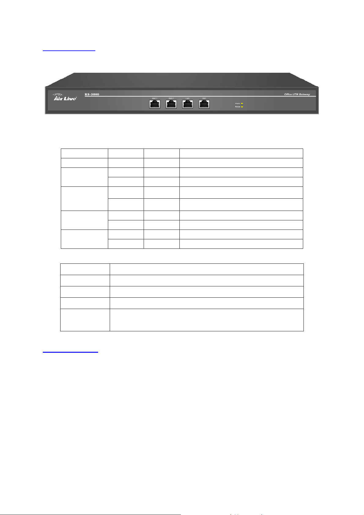
1.2 Front Panel
LED Color Status Description
POWER Green On Power on the device
Status
Figure 1-1 Front Panel
Green On Device is ready to use
Blinking Device is at the booting process
WAN 1/2
LAN
DMZ
Port Description
WAN 1/2
LAN
DMZ
Console Port
Green Blinking Packets is sending/receiving
Orange On Cable speed is 100 Mbps
Green Blinking Packets is sending/receiving
Orange On Cable speed is 100 Mbps
Green Blinking Packets is sending/receiving
Orange On Cable speed is 100 Mbps
Use this port to connect to a router, DSL modem, or Cable modem
Use this port to connect to the LAN network of the office
Connection to the Internet (FTP, SNMP, HTTP, DNS)
9-pin serial port connector for checking setting and restore to the
factory setting
1.3 Packing List
RS-3000 Office UTM Gateway
Installation CD-ROM
Quick Installation Guide
CAT-5 UTP Fast Ethernet cable
CAT-5 UTP Fast Ethernet cross-over cable
RS-232 cable
Power code
Accessories
5
Page 8

f
t
w
a
r
e
I
n
s
t
a
l
l
a
t
i
C
h
a
p
t
e
r
2
N
e
t
w
o
r
k
S
e
t
t
i
n
g
s
a
n
d
S
o
o
f
t
w
a
r
e
I
n
s
t
C
h
a
p
t
e
r
2
N
e
t
w
o
r
k
S
e
t
t
i
n
g
s
a
n
d
S
f
t
w
a
r
C
h
a
p
t
e
r
2
N
e
t
w
o
r
k
S
e
t
t
i
n
g
s
a
n
d
S
o
To use this product correctly, you have to properly configure the network settings of your comp uters and
install the attached setup program into your MS Windows platform (Windows 95/98/NT/2000/XP).
2.1 Make Correct Network Settings of Your Computer
The default IP address of this product is 192.168.1.1, and the default subnet mask is 255.255.255.0.
These addresses can be changed on your need, but the default values are used in this manual. If the
TCP/IP environment of your computer has not yet been configured, you can refer to the example:
1. Configure IP as 192.168.1.2, subnet mask as 255.255.255.0 and gateway as 192.168.1.1, or
more easier,
2. Configure your computers to load TCP/IP setting automatically, that is, via DHCP server of this
product.
After installing the TCP/IP communication protocol, you can use the ping command to check if your
e
a
I
n
s
t
o
n
l
l
a
a
l
l
a
t
i
o
n
t
i
o
n
computer has successfully connected to this product. The following example shows the ping procedure
for Windows platforms. First, execute the ping command
ping 192.168.1.1
If the following messages appear:
Pinging 192.168.1.1 with 32 bytes of data:
Reply from 192.168.1.1: bytes=32 time=2ms TTL=64
A communication link between your computer and this product has been successfully established.
Otherwise, if you get the following messages,
Pinging 192.168.1.254 with 32 bytes of data:
Request timed out.
There must be something wrong in your installation procedure. You have to check the following items in
sequence:
1. Is the Ethernet cable correctly connected between this product and your computer?
Tip: The LAN LED of this product and the link LED of network card on your computer must be
lighted.
2. Is the TCP/IP environment of your computers properly configured?
Tip: If the IP address of this product is 192.168.1.1, the IP address of your computer must be
192.168.1.X and default gateway must be 192.168.1.1.
6
Page 9
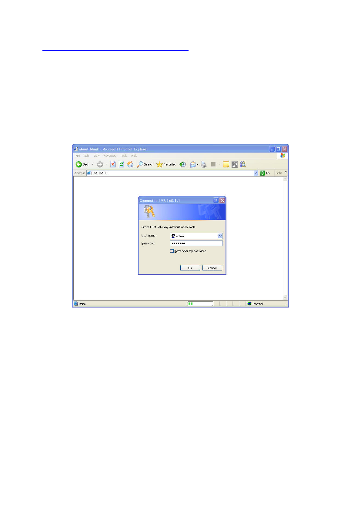
2.2 Example for configure RS-3000 Web UI
STEP 1:
1. Connect the Admin’s PC and the LAN port of the Security Gatewa y.
2. Open an Internet web browser and type the default IP address of the Security Gateway as
192.168.1.1 in the address bar.
3. A pop-up screen will appear and prompt for a username and password. Enter the default login
username (admin) and password (airlive) of Administrator.
Figure 2-1 Login page
STEP 2:
After entering the username and password, the Security Gateway WEB UI screen will display. Select
the Interface tab on the left menu and a sub-function list will be displayed.
Click on WAN from the sub-function list, enter proper the network setup information
Click Modify to modify WAN1/2 settings (i.e. WAN1 Interface)
WAN1 interface IP Address 60.250.158.66
NetMask 255.255.255.0
Default Gateway 60.250.158.254
DNS Server1 168.95.1.1
7
Page 10

Figure 2-2 WAN interface setting page
STEP 3:
Click on the Policy tab from the main function menu, and then click on Outgoing from the sub-function
list.
STEP 4:
Click on New Entry button.
STEP 5:
When the New Entry option appears, enter the following configuration:
Source Address – select Inside_Any
Destination Address – select Outside_Any
Service - select ANY
Action - select Permit ALL
Click on OK to apply the changes.
8
Page 11
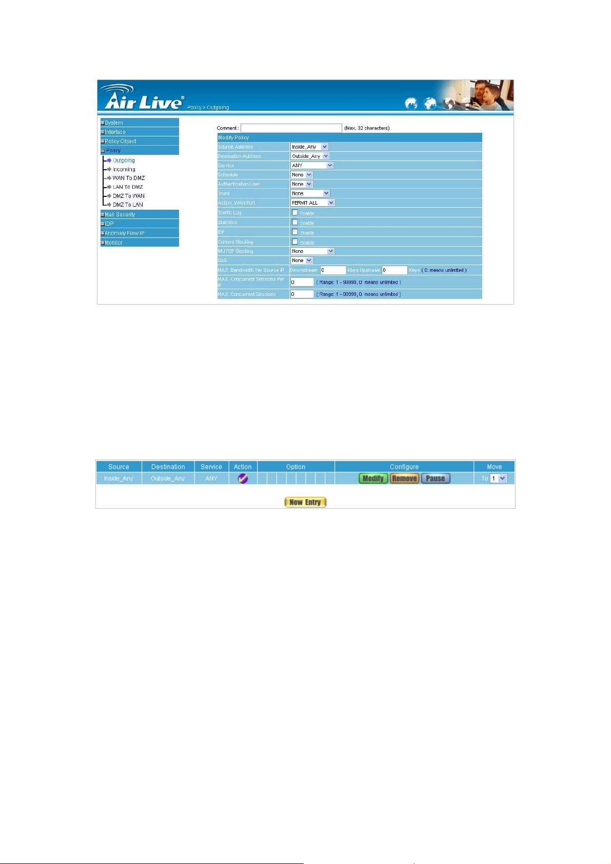
Figure 2-3 Policy setting page
STEP 6:
The configuration is successful when the screen below is displayed. Make sure that all the computers
that are connected to the LAN port have their Default Gateway IP Address set to the Security Gateway’ s
LAN IP Address (i.e. 192.168.1.1). At this point, all the computers on the LAN network should gain
access to the Internet immediately.
Figure 2-4 Complete Policy setting page
9
Page 12

C
h
a
p
t
e
r
3
A
d
m
i
n
i
s
t
r
a
t
i
o
n
C
h
a
p
t
e
r
3
A
d
m
i
n
i
s
t
r
C
h
a
p
t
e
r
3
A
d
m
i
“System” is the managing of settings such as the privileges of packets that pass through the RS-3000
and monitoring controls. The System Administrators can manage, monitor, and configure RS-3000
settings. But all configurations are “read-only” for all users other than the System Administrator; those
users are not able to change any setting of the RS-3000.
3.1 Admin
Administrator Name:
The username of Administrators and Sub Administrator for the RS-3000. The admin user name
cannot be removed; and the sub-admin user can be removed or modified.
The default Account: admin; Password: airlive
n
a
i
s
t
r
a
t
i
o
n
t
i
o
n
Privilege:
The privileges of Administrators (Admin or Sub Admi n). The username of the mai n Administ rator is
Administrator with reading / writing privilege. Administrator al so can cha ng e the system setting,
log system status, and to increase or delete sub-administrator. Sub-Admin may be created by the
Admin by clicking
cannot change any system setting value.
Configure:
Click Modify to change the “Sub-Administrator’s” password or click Remove to delete a “Sub
Administrator.”
New Sub Admin
. Sub Admin have only read and monitor privilege and
10
Page 13
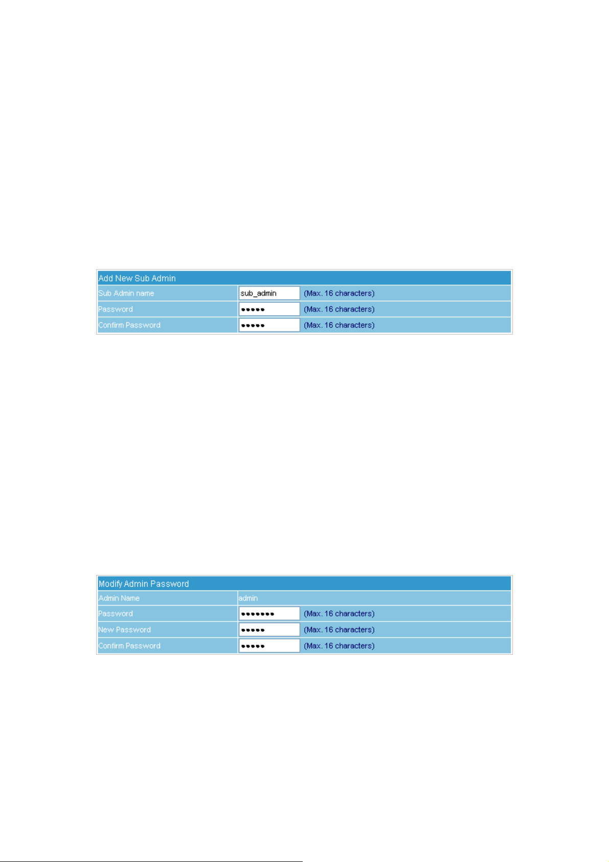
Adding a new Sub Administrator
STEP 1﹒In the Admin WebUI, click the New Sub Admin button to create a new Sub Administrator .
STEP 2
STEP 3
﹒
In the Add New Sub Administrator WebUI (Figure 3-1) and enter the following setting:
Sub Admin Name: sub_admin
Password: 12345
Confirm Password: 12345
﹒
Click OK to add the user or click Cancel to cancel it.
Figure 3-1 Add New Sub Admin
Modify the Administrator’s Password
STEP 1﹒In the Admin WebUI, locate the Administrator name you want to edit, and click on Modify in
the Configure field.
STEP 2
STEP 3
﹒
The Modify Administrator Password WebUI will appear. Enter the following information:
Password: admin
New Password: 52364
Confirm Password: 52364 (Figure 3-2)
﹒
Click OK to confirm password change.
Figure 3-2 Modify Admin Password
11
Page 14
3.2 Permitted IP
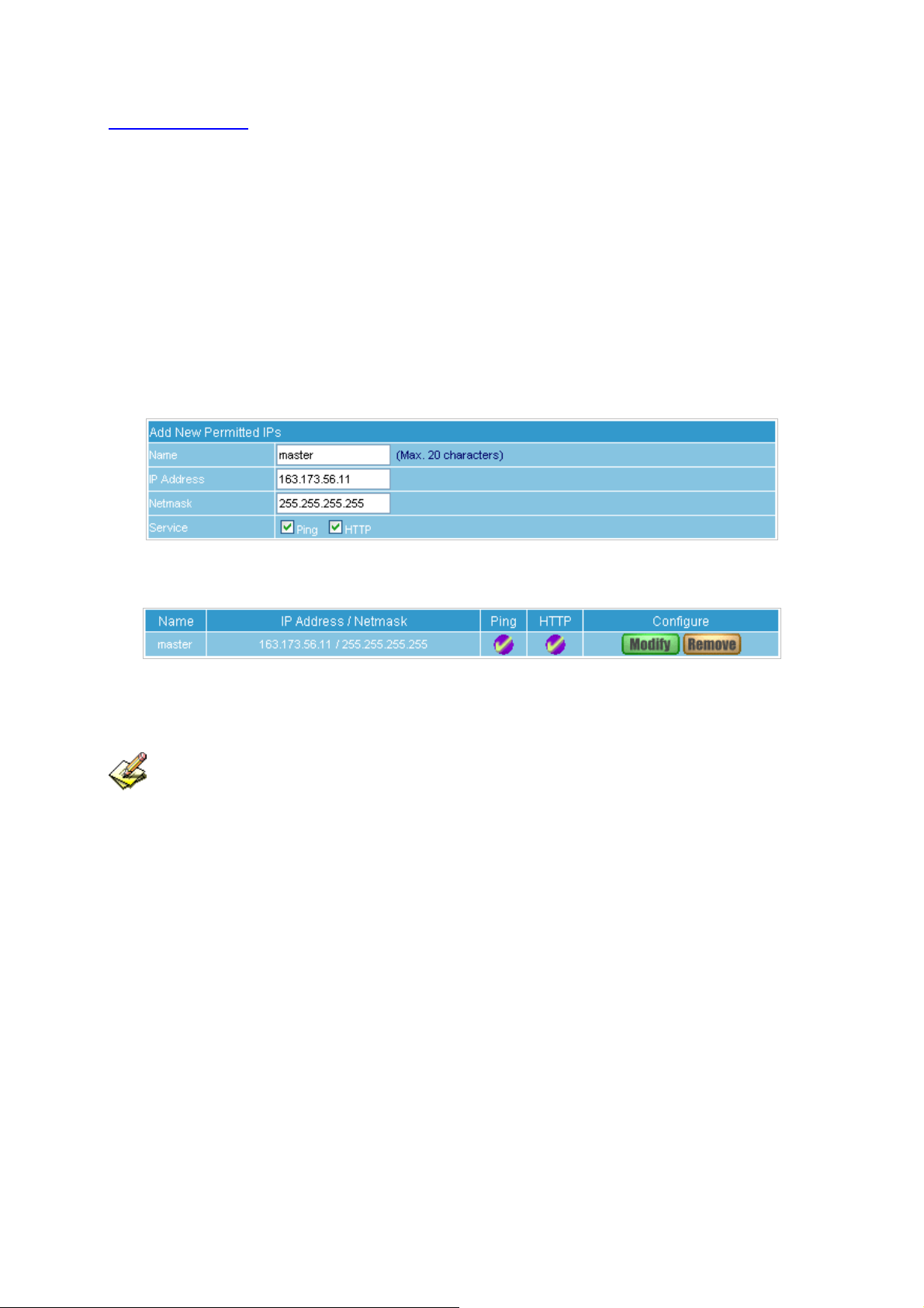
Add Permitted IPs
STEP 1﹒Add the following setting in Permitted IPs of Administration: (Figure 3-3)
Name: Enter master
IP Address: Enter 163.173.56.11
Netmask: Enter 255.255.255.255
Service: Select Ping and HTTP
Click OK
Complete add new permitted IPs (Figure 3-4)
Figure 3-3 Setting Permitted IPs WebUI
Figure 3-4 Complete Add New Permitted Ips
To make Permitted IPs be ef fective, it must cancel the Ping and WebUI selection in the WebUI of
RS-3000 that Administrator enter. (LAN, WAN, or DMZ Interface)
Before canceling the WebUI selection of Interface, must set up the Permitted IPs first, otherwise, it
would cause the situation of cannot enter WebUI by appointed Interface.
12
Page 15
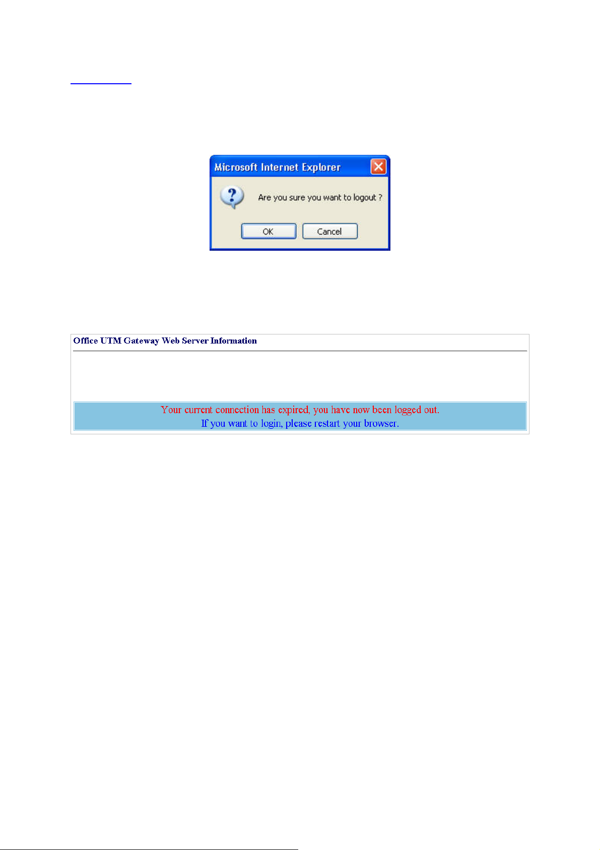
3.3 Logout
STEP 1﹒Click Logout in System to protect the system while Administrator is away. (Figure 3-5)
Figure 3-5 Confirm Logout WebUI
STEP 2﹒Click OK and the logout message will appear in WebUI. (Figure 3-6)
Figure 3-6 Logout WebUI Message
13
Page 16
3.4 Software Update
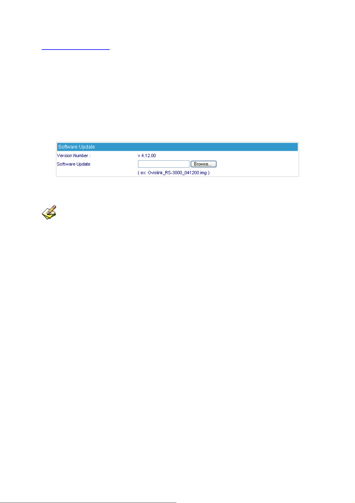
STEP 1
﹒
Select Software Update in System, and follow the steps below:
To obtain the version number from Version Number and obtain the latest version from
Internet. And save the latest version in the hardware of the PC, which manage the
RS-3000
Click Browse and choose the latest software version file.
Click OK and the system will update automatically. (Figure 3-7)
Figure 3-7 Software Update
It takes 3 minutes to update software. The system will reboot after update. During the updating
time, please don’t turn off the PC or leave the WebUI. It may cause some unexp ected mi sta kes. (Strong
suggests updating the software from LAN to avoid unexpected mistakes.)
14
Page 17

C
h
a
p
t
e
r
4
C
o
n
f
i
g
u
r
e
C
h
a
p
t
e
r
4
C
o
n
f
C
h
a
p
t
e
r
4
C
The Configure is according to the basic setting of the RS-3000. In this chapter the definition is Setting,
Date/Time, Multiple Subnet, Route Table, DHCP, Dynamic DNS, Hosts Table, SNMP and Language
settings.
4.1 Setting
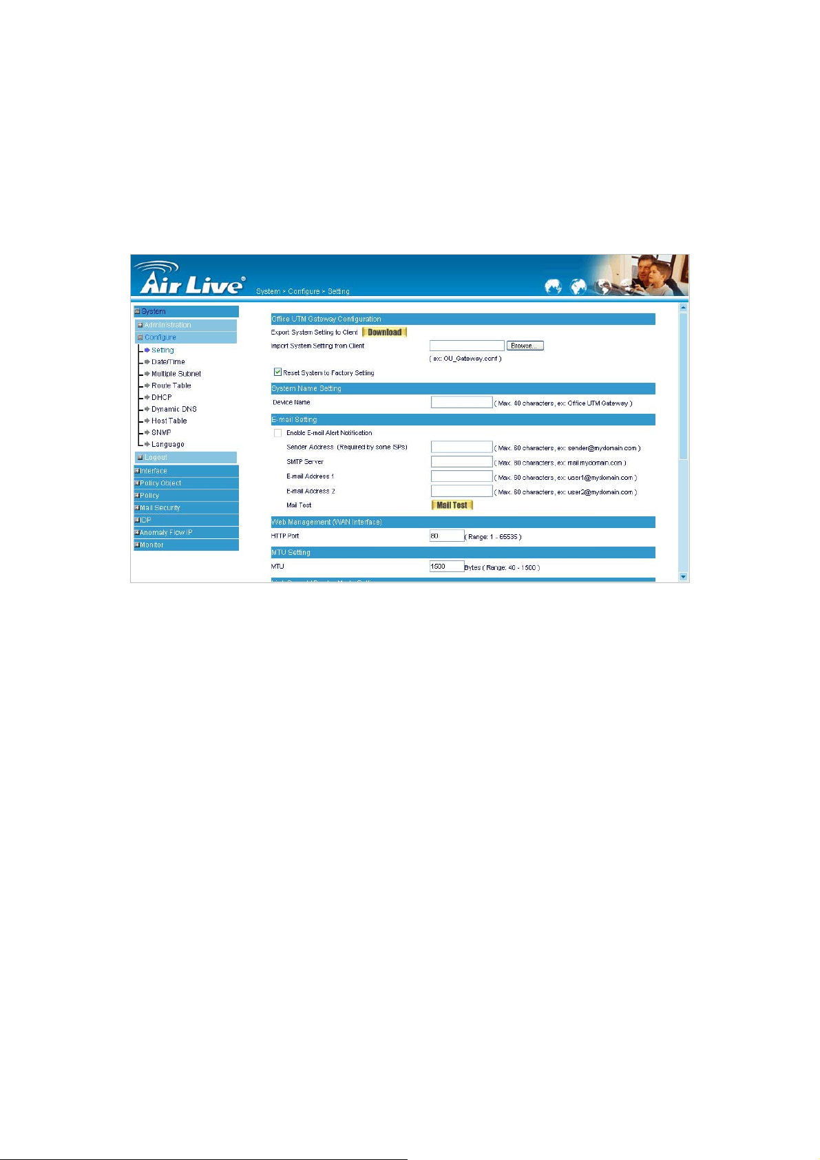
AirLive RS-3000 Configuration:
The Administrator can import or export the system settings. Click OK to import the file into the
RS-3000 or click Cancel to cancel importing. You also can revive to default value here.
Select Reset Factory Setting will reset RS-3000 as factory default setting.
Email Settings:
Select Enable E-mail Alert Notification under E-mail Settings. This function will enable the
RS-3000 to send e-mail alerts to the System Administrator when the network is being attacked by
o
n
i
f
i
g
g
u
u
r
e
r
e
hackers or when emergency conditions occur. (It can be set from Anomaly Flow IP Setting to
detect Hacker Attacks)
Web Management (WAN Interface):
The System Manager can change the port number used by HTTP port anytime. (Remote WebUI
management)
After HTTP port has changed, if the administrator wants to enter WebUI from WAN, will have to
change the port number of browser. (For example: http://61.62.108.172:8080)
MTU Setting:
It provides the Administrator to modify the networking package length anytime. Its default value is
1500 Bytes.
Link Speed / Duplex Mode:
By this function can set the transmission speed and mode of WAN Port when connecting other
device.
Dynamic Routing (RIPv2):
Select to enable the function of AirLive RS-3000 LAN, WAN1, WAN2 or DMZ Port to send/receive
RIPv2 packets, and communication between Internal Router or External Router, to update
Dynamic Routing.
15
Page 18

SIP protocol pass-through:
Select to enable the function of RS-3000 of passing SIP protocol. It is also possible that the SIP
protocol can pass through RS-3000 without enabling this function depends on the SIP device’s
type you have.
Administration Packet Logging:
After enable this function; the RS-3000 will record packet which source IP or destination address
is RS-3000. And record in Traffic Log for System Manager to inquire about.
System Reboot:
Once this function is enabled, the Office UTM Gateway will be rebooted.
16
Page 19
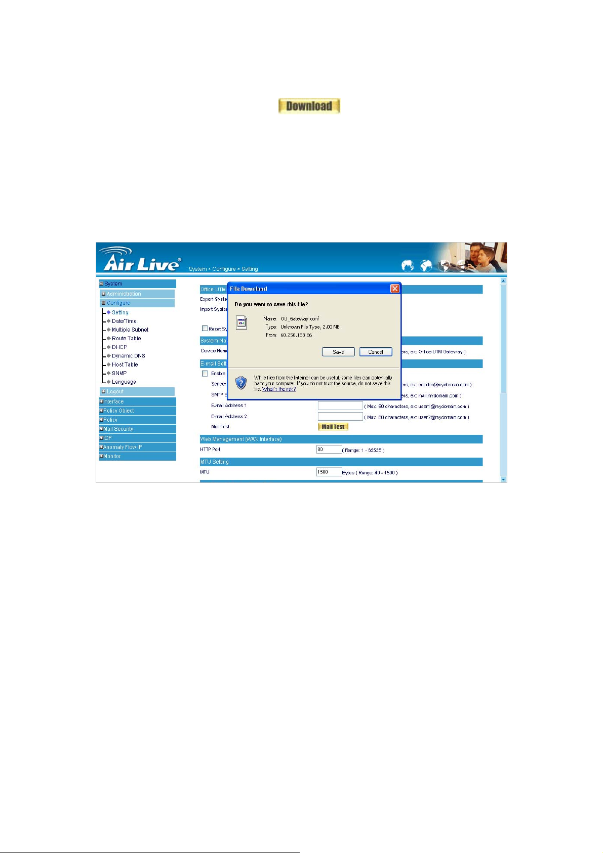
System Settings- Exporting
STEP 1﹒In System Setting WebUI, click on button next to Export System Settings to
Client.
STEP 2
﹒
When the File Download pop-up window appears, choose the destination place where to
Sav
save the exported file and click on
appointed site instantly. (Figure 4-1)
e. The setting value of RS-3000 will copy to the
Figure 4-1 Select the Destination Place to Save the Exported File
17
Page 20

System Settings- Importing
STEP 1﹒In System Setting WebUI, click on the Browse button next to Import System Settings from
Client. When the Choose File pop-up window appears, select the file to which contains the
saved RS-3000 Settings, then click OK. (Figure 4-2)
STEP 2
﹒
Click OK to import the file into the RS-3000 (Figure 4-3)
Figure 4-2 Enter the File Name and Destination of the Imported File
Figure 4-3 Upload the Setting File WebUI
18
Page 21
Restoring Factory Default Settings
STEP 1﹒Select Reset Factory Settings in RS-3000 Configuration WebUI
STEP 2
﹒
Click OK at the bottom-right of the page to restore the factory settings. (Figure 4-4)
Figure 4-4 Reset Factory Settings
19
Page 22
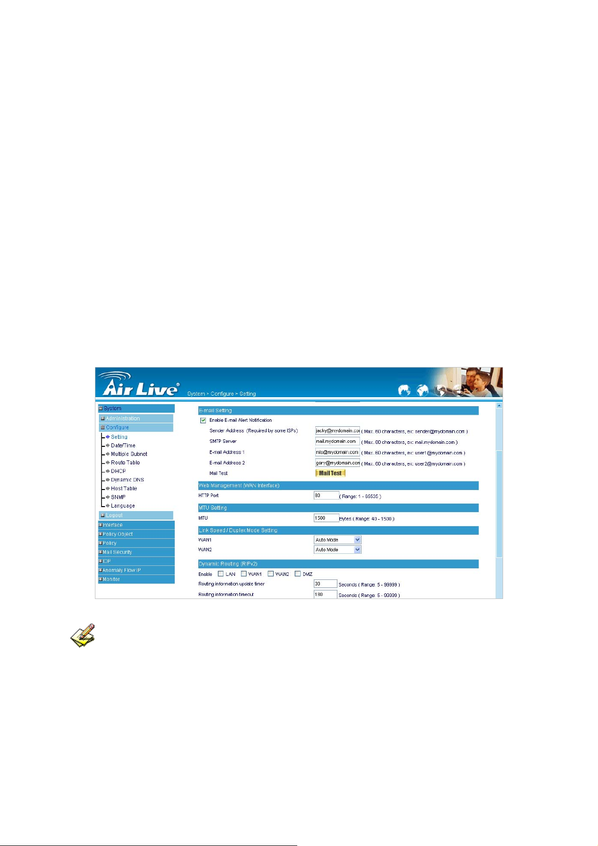
Enabling E-mail Alert Notification
STEP 1﹒Select Enable E-mail Alert Notification under E-Mail Settings.
STEP 2
STEP 3
STEP 4
STEP 5
STEP 6
STEP 7
﹒
Device Name: Enter the Device Name or use the default value.
﹒
Sender Address: Enter the Sender Address. (Required by some ISPs.)
﹒
SMTP Server IP: Enter SMTP server’s IP address
﹒
E-Mail Address 1: Enter the e-mail address of the first user to be notified.
﹒
E-Mail Address 2: Enter the e-mail address of the second user to be notified. (Optional)
﹒
Click OK on the bottom-right of the screen to enable E-mail Alert Notification. (Figure 4-5)
Figure 4-5 Enable E-mail Alert Notification
Click on Mail Test to test if E-mail Address 1 and E-mail Address 2 can receive the Alert
Notification correctly.
20
Page 23

Reboot RS-3000
STEP 1
STEP 2
STEP 3
﹒
Reboot RS-3000:Click Reboot button next to Reboot RS-3000 Appliance.
﹒
A confirmatio n pop-up page will appear.
﹒
Follow the confirmation pop-up page; click OK to restart RS-3000. (Figure 4-6)
Figure 4-6 Reboot RS-3000
21
Page 24
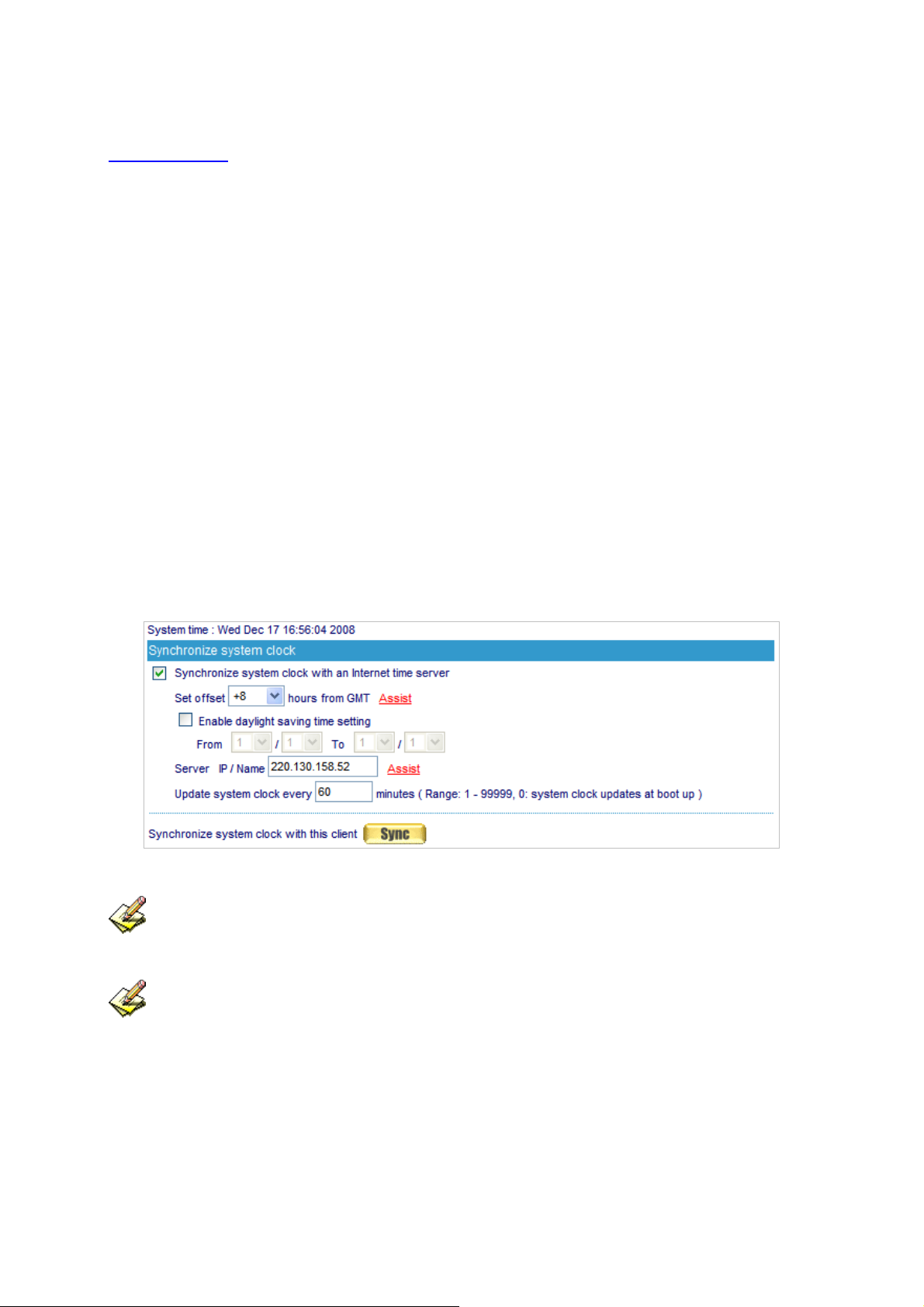
4.2 Date/Time
Synchronize system clock:
Synchronizing the RS-3000 with the System Clock. The administrator can configure the
RS-3000’s date and time by either syncing to an Internet Network Time Server (NTP) or by
syncing to your computer’s clock.
STEP 1
STEP 2
STEP 3
STEP 4
STEP 5
﹒
Select Enable synchronize with an Internet time Server (Figure 4-7)
﹒
Click the down arrow to select the offset time from GMT.
﹒
If necessary, select Enable daylight saving time setting
﹒
Enter the Server IP / Name with which you want to synchronize.
﹒
Set the interval time to synchronize with outside servers.
Figure 4-7 System Time Setting
Click on the Sync button and then the RS-3000’s date and time will be synchronized to the
Administrator’s PC
The value of Set Offset From GMT and Server IP / Name can be looking for from Assist.
22
Page 25

4.3 Multiple Subnet
Connect to the Internet through Multiple Subnet NAT or Routing Mode by the IP address that set by the
LAN user’s network card.
Alias IP of Interface / Netmask:
The Multiple Subnet range
WAN Interface IP:
The IP address that Multiple Subnet corresponds to WAN.
Forwarding Mode:
To display the mode that Multiple Subnet use. (NAT mode or Routing Mode)
Preparation
RS-3000 WAN1 (60.250.158.66) connect to the ISP Router (60.250.158.254) and the subnet that
provided by ISP is 162.172.50.0/24
To connect to Internet, WAN2 IP (211.22.22.22) connects with ATUR.
23
Page 26
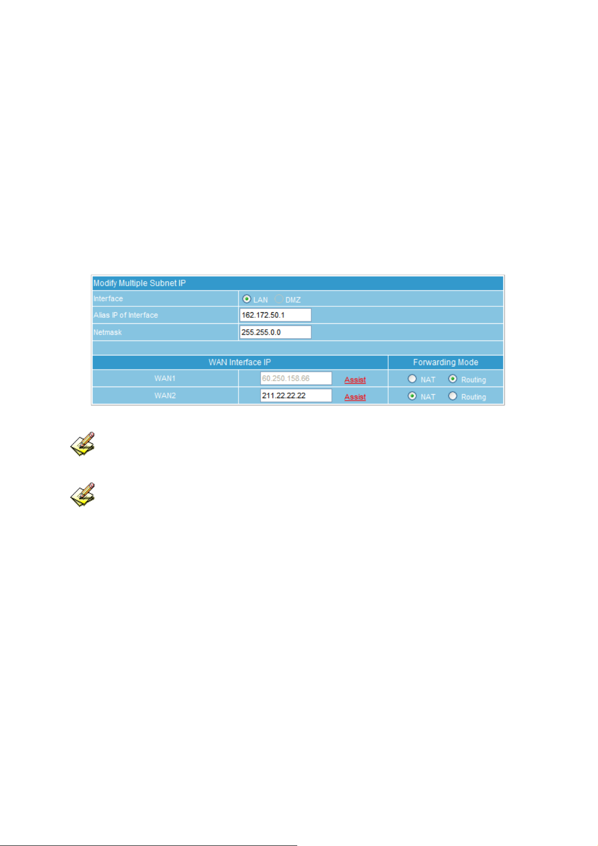
Adding Multiple Subnet
Add the following settings in Multiple Subnet of System function:
Click on New Entry
Alias IP of LAN Interface: Enter 162.172.50.1
Netmask:Enter 255.255.255.0
WAN1: Choose Routing in Forwarding Mode, and press Assist to select Interface
IP 60.250.158.66.
WAN2:Enter Interface IP 211.22.22.22, and choose NAT in Forwarding Mode
Click OK
Complete Adding Multiple Subnet (Figure 4-8)
Figure 4-8 Add Multiple Subnet WebUI
WAN1 and WAN2 Interface can use Assist to enter the data.
After setting, there will be two subnets in LAN: 192.168.1.0/24 (default LAN subnet) and
162.172.50.0/24. So if LAN IP is:
192.168.1.x: it must use NAT Mode to access to the Internet. (In Policy it only can setup to access to
Internet by WAN2. If by WAN1 Routing mode, then it cannot access to Internet by its virtual IP)
162.172.50.x: it uses Routing mode through WAN1 (The Internet Server can see your IP 162.172.50.x
directly). And uses NAT mode through WAN2 (The Internet Server can see your IP as WAN2 IP)
24
Page 27

NAT Mode:
It allows Internal Network to set multiple subnet address and connect with the Internet through
different WAN IP Addresses. For example:The lease line of a company applies several real IP
Addresses 168.85.88.0/24, and the company is divided into Service, Sales, Procurement, and
Accounting department, the company can disting uish each depart ment by dif ferent subnet for the
purpose of managing conveniently. The settings are as the following:
1. R&D department subnet:192.168.1.1/24 (LAN) 168.85.88.253 (WAN)
2. Service department subnet:192.168.2.1/24 (LAN) 168.85.88.252 (WAN)
3. Sales department subnet:192.168.3.1/24 (LAN) 168.85.88.251 (WAN)
4. Procurement department subnet:192.168.4.1/24 (LAN) 168.85.88.250 (WAN)
5. Accounting department subnet:192.168.5.1/24 (LAN) 168.85.88.249 (WAN)
The first department (R&D department) had set while setting interface IP; the other fou r ones have to be
added in Multiple Subnet. After completing the settings, each department uses the different WAN IP
Address to connect to the Internet. The settings of each department are as following:
Service Sales Procurement Accounting
IP Address 192.168.2.2~254 192.168.3.2~254 192.168.4.2~254 192.168.5.2~254
Subnet Netmask 255.255.255.0 255.255.255.0 255.255.255.0 255.255.255.0
Gateway 192.168.2.1 192.168.3.1 192.168.4.1 192.168.5.1
Routing Mode:
It is the same as NAT mode approximately but does not have to correspond to the real WAN IP
address, which let internal PC to access to Internet by its own IP. (External user also can use the
IP to connect with the Internet)
25
Page 28
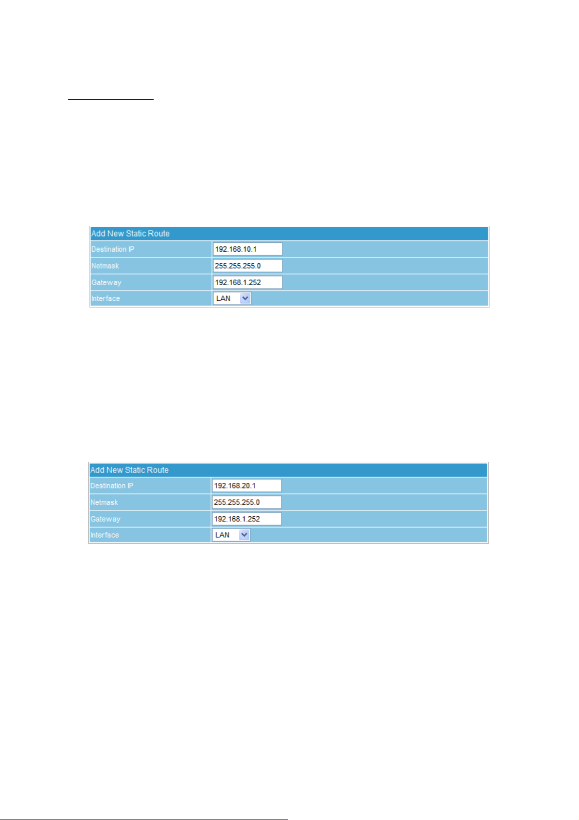
4.4 Route Table
STEP 1
﹒
Enter the following settings in Route Table in System function:
【Destination IP】: Enter 192.168.10.1
【Netmask】: Enter 255.255.255.0。
【Gateway】: Enter 192.168.1.252
【Interface】: Select LAN
Click OK (Figure 4-9)
Figure 4-9 Add New Static Route1
STEP 2﹒Enter the following settings in Route Table in System function:
【Destination IP】: Enter 192.168.20.1
【Netmask】: Enter 255.255.255.0
【Gateway】: Enter 192.168.1.252
STEP 3
【Interface】: Select LAN
Click OK (Figure 4-10)
Figure 4-10 Add New Static Route2
﹒
Enter the following setting in Route Table in System function:
【Destination IP】: Enter 10.10.10.0
【Netmask】: Enter 255.255.255.0
【Gateway】: Enter 192.168.1.252
【Interface】: Select LAN
Click OK (Figure 4-11)
26
Page 29
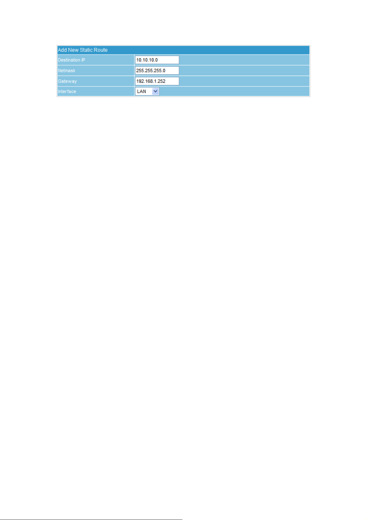
Figure 4-11 Add New Static Route3
STEP 4﹒Adding successful. At this time the computer of 192.168.10.1/24, 192.168.20.1/24 and
192.168.1.1/24 can connect with each other and connect to Internet by NAT.
27
Page 30

4.5 DHCP
Subnet: The domain name of LAN
NetMask: The LAN Netmask
Gateway: The default Gateway IP address of LAN
Broadcast IP: The Broadcast IP of LAN
STEP 1﹒Select DHCP in System and enter the following settings:
Domain Name:Enter the Domain Name
DNS Server 1: Enter the distributed IP address of DNS Server1.
DNS Server 2: Enter the distributed IP address of DNS Server2.
WINS Server 1: Enter the distributed IP address of WINS Server1.
WINS Server 2: Enter the distributed IP address of WINS Server2.
LAN Interface:
Client IP Address Range 1:
Enter the starting and the ending IP address dynamically assigning to DHCP clients.
The default value is 192.168.1.2 to 192.168.1.254 (it must be in the same subnet)
Client IP Address Range 2:
Enter the starting and the ending IP address dynamically assigning to DHCP clients.
But it must be within the same subnet as Client IP Address Range 1 and the range
cannot be repeated.
DMZ Interface: the same as LAN Interface. (DMZ works only if to enable DMZ Interface)
Leased Time: Enter the leased time for Dynamic IP. The default time is 24 hours.
Click OK and DHCP setting is completed. (Figure 4-12)
28
Page 31

Figure 4-12 DHCP WebUI
When selecting Automatically Get DNS, the DNS Server will be locked as LAN Interface IP.
(Using Occasion: When the system Administrator st art s Authenticati on, the users’ first DNS Server must
be the same as LAN Interface IP in order to enter Authentication WebUI)
29
Page 32

4.6 Dynamic DNS
STEP 1
﹒
Select Dynamic DNS in System function (Figure 4-13). Click New Entry button
Service providers:Select service providers.
Automatically fill in the WAN 1/2 IP:Check to automatically fill in the WAN 1/2 IP.。
User Name:Enter the registered user name.
Password:Enter the password.
Domain name:Enter Your host domain name
Click OK to add Dynamic DNS. (Figure 4-14)
Figure 4-13 DDNS WebUI
Figure 4-14 Complete DDNS Setting
Chart
Meaning Update
successfully
Incorrect username
or password
Connecting to
server
Unknown error
If System Administrator had not registered a DDNS account, click on Sign up then can enter the
website of the provider.
If you do not select Automatically fill in the WAN IP and then you can enter a specific IP in
WAN IP. DDNS corresponds to that specific IP address.
30
Page 33

4.7 Host Table
Host Name:
It can be set by System Manager, to allow internal user accessing the information provided by the host
of the domain.
Virtual IP Address:
The virtual IP address is corresponding to the Host. It must be LAN or DMZ IP address.
STEP 1
﹒
Select Host Table in Settings function and click on New Entry
Host Name: The domain name of the server
Virtual IP Address: The virtual IP address is corresponding to the Host.
Click OK to add Host Table. (Figure 4-15)
Figure 4-15 Add New Host Table
To use Host Table, the user PC’s first DNS Server must be the same as the LAN Port or DMZ
Port IP of RS-3000. That is, the default gateway.
31
Page 34

4.8 SNMP
STEP 1﹒ Select SNMP in Settings function, click Enable SNMP Agent and type in the following
information:
Device Name: The default setting is “Office UTM Gateway”, and user can change it.
Device Location: The default setting is “Taipei, Taiwan”, and user can change it.
Community: The default setting is “public”, and user can change it.
Contact Person: The default setting is “root@public”, and user can change it.
Description: The default setting is “Office UTM gateway Appliance”, and user can
change it.
Click OK.
The SNMP Agent setting is done. So administrator can install SNMP management
software on PC and monitor RS-3000 via SNMP Agent. (Figure 4-16)
Figure 4-16 SNMP Agent setting
32
Page 35

STEP 2
﹒
Select SNMP in Settings function, click Enable SNMP Trap Alert Notification and type in
the following information:
SNMP Trap Receiver Address: Input SNMP Trap Receiver site of IP address
SNMP Trap Port: Input the port number.
Click OK.
SNMP Trap setting is done. So administrator can receive alert message from PC
installed with SNMP management soft ware, via RS-3000 SNMP Trap function.
(System will transfer the alert messages to specific IP address, when RS-3000 is
attacked by hacker, or connect/disconnect status of line. (Figure 4-17)
Figure 4-17 SNMP Trap setting
4.9 Language
Select the Language version (English Version/ Traditional Chinese Version or Simplified Chinese
Version) and click OK. (Figure 4-18)
Figure 4-18 Language Setting WebUI
33
Page 36

C
h
a
p
t
e
r
5
I
n
t
e
r
f
a
c
e
C
h
a
p
t
e
r
5
I
n
t
e
C
h
a
p
t
e
r
5
In this section, the Administrator can set up the IP addresses for the office network.
The Administrator may configure the IP addresses of the LAN network, the WAN 1/2 network, and the
DMZ network.
The Netmask and gateway IP addresses are also configured in this section.
Define the required fields of Interface
LAN: Using the LAN Interface, the Administrator can set up the LAN network of RS-3000.
Ping: Select this function to allow the LAN users to ping the Interface IP Address.
HTTP: Select to enable the user to enter the WebUI of RS-3000 from Interface IP.
WAN: The System Administrator can set up the WAN network of RS-3000.
Balance Mode:
r
I
n
t
e
r
f
a
c
e
f
a
c
e
Auto: The RS-3000 will adjust the WAN 1/2 utility rate automatically according to the
downstream/upstream of WAN. (For users who are using various download bandwidth)
Round-Robin: The RS-3000 distributes the WAN 1/2 download bandwidth 1:1, in other words, it
selects the agent by order. (For users who are using same download bandwidths)
By Traffic: The RS-3000 distributes the WAN 1/2 download bandwidth by accumulative traffic.
By Session: The RS-3000 distributes the WAN 1/2 download bandwidth by saturated
connections.
B y Packet: The RS-3000 distributes the WAN 1/2 download bandwidth by accumulated packets
and saturated connection.
B y Source IP: The RS-3000 distributes the WAN 1/2 connection by source IP address, once the
connection is built up, all the packets from the same source IP will pass through the same WAN
interface.
By Destination IP: The RS-3000 will allocate the WAN connection corresponding to the
destination IP, once the connection is built up, all the packets to the same destination IP will pass
through the same WAN interface. The connection will be re-assigned with WAN interface when the
connections are stopped.
34
Page 37

Connect Mode:
Display the current connection mode:
PPPoE (ADSL user)
Dynamic IP Address (Cable Modem User)
Static IP Address
PPTP (European User Only)
Saturated Connections:
Set the number for saturation whenever session numbers reach it, the RS-3000 switches to the
next agent on the list.
Priority:
Set priority of WAN for Internet Access.
Connection Test:
The function works to identify WAN port’s connection status. The te sting ways are as following:
ICMP:User can define the IP address and RS-3000 will ping the address to verify WAN
port’s connection status.
DNS:Another way to verify the connection status by checking the DNS server and Domain
Name configured by user.
Upstream/Downstream Bandwidth:
The System Administrator can set up the correct Bandwidth of WAN network Interface here.
Auto Disconnect:
The PPPoE connection will automatically disconnect after a length of idle time (no activities). Enter
“0” means the PPPoE connection will not disconnect at all.
DMZ:
The Administrator uses the DMZ Interface to set up the DMZ network.
The DMZ includes:
NAT Mode:In this mode, the DMZ is an independent virtual subnet. This virtual subnet can
be set by the Administrator but cannot be the same as LAN Interface.
Transparent Mode: In this mode, the DMZ and WAN Interface are in the same subnet.
35
Page 38

5.1 LAN
Modify LAN Interface Settings
STEP 1﹒Select LAN in Interface and enter the following setting:
Enter the new IP Address and Netmask
Select Ping and HTTP
Click OK (Figure 5-1)
Figure 5-1 Setting LAN Interface WebUI
The default LAN IP Address is 192.168.1.1. After the Administrator setting the new LAN IP
Address on the computer , he/she have to restart the System to make the new IP address effective.
(when the computer obtain IP by DHCP)
Do not cancel WebUI selection before not setting Permitted IPs yet. It will cause the
Administrator cannot be allowed to enter the RS-3000 WebUI from LAN.
36
Page 39

5.2 WAN
Setting WAN Interface Address
STEP 1﹒Select WAN in Interface and click Modify in WAN1 Interface.
The setting of WAN2 Interface is almost the same as WAN1. The difference is that WAN2 has a
selection of Disable. The System Administrator can close W AN2 Interface by this selection. (Fi gure 5-2)
Figure 5-2 Disable WAN2 Interface
37
Page 40

STEP 2
﹒
Setting the Connection Service (ICMP or DNS way):
ICMP:Enter an Alive Indicator Site IP (can select from Assist) (Figure 5-3)
DNS:Enter two different DNS Server IP Address and Domain Name (can select from
Assist) (Figure 5-4)
Setting time of seconds between sending alive packet.
Figure 5-3 ICMP Connection
Figure 5-4 DNS Service
Connection test is used for RS-3000 to detect if the WAN can connect or not. So the Alive
Indicator Site IP, DNS Server IP Address, or Domain Name must be able to use permanently. Or it
will cause judgmental mistakes of the device.
38
Page 41

STEP 3
﹒
Select the Connecting way:
PPPoE (ADSL User) (Figure 5-5):
1. Select PPPoE
2. Enter User Name as an account
3. Enter Password as the password
4. Select Dynamic or Fixed in IP Address prov ided by ISP.
If you select Fixed, please enter IP Address, Netmask, and Default Gateway.
5. Enter Max. Downstream Bandwidth and Max. Upstream Bandwidth. (According to
the flow that user apply)
6. Select Ping and HTTP
7. Click OK (Figure 5-6)
Figure 5-5 PPPoE Connection
Figure 5-6 Complete PPPoE Connection Setting
You can set up Auto Disconnect if idle, in order to disconnect the PPPoE when the idle time is
up, and save the network expense.
39
Page 42

Dynamic IP Address (Cable Modem User ) (Figure 5-7) :
1. Select Dynamic IP Address (Cable M odem User)
2. Click Renew in the right side of IP Address and then can obtain IP automatically .
3. If the MAC Address is required for ISP then click on Clone MAC Address to obtain
MAC IP automatically.
4. Hostname: Enter the hostname provided by ISP.
5. Domain Name: Enter the domain name provided by ISP.
6. User Name and Password are the IP distribution method according to Authentication
way of DHCP + protocol
7. Enter Max. Downstream Bandwidth and Max. Upstream Bandwidth (According to
the flow applied by user)
8. Select Ping and HTTP
9. Click OK (Figure 5-8)
Figure 5-7 Dynamic IP Address Connection
Figure 5-8 Complete Dynamic IP Connection Setting
40
Page 43

St
atic IP Address (Figure 5-9)
1. Select Static IP Address
2. Enter IP Address, Netmask, and Default Gateway that provided by ISP
3. Enter DNS Server1 and DNS Server2
In WAN2, the connecting of Static IP Address does not need to set DNS Server
4. Enter Max. Downstream Bandwidth and Max. Upstream Bandwidth (According to
the flow applied by user)
5. Select Ping and HTTP
6. Click OK (Figure 5-10)
Figure 5-9 Static IP Address Connection
Figure 5-10 Complete Static IP Address Connection Setting
When selecting Ping and WebUI on WAN network Interface, users will be able to ping the
RS-3000 and enter the WebUI WAN network. It may influence network security. The suggestion is to
Cancel Ping and WebUI after all the settings have finished. And if the System Administrator needs to
enter UI from WAN, he/she can use Permitted IPs to enter.
41
Page 44

PPTP
(European User Only) (Figure 5-11):
1. Select PPTP (European User Only)
2. Enter User Name as an account.
3. Enter Password as the password.
4. If the MAC Address is required for ISP then click on Clone MAC Address to obtain
MAC IP automatically.
5. Select Obtain an IP address automatically or Use the following IP address
provided by ISP.
6. Hostname: Enter the hostname provided by ISP.
7. Domain Name: Enter the domain name provided by ISP.
8. If user selects Use the follo wing IP address, please enter IP Address, Netmask, and
Default Gateway.
9. Enter PPTP server IP address as the PPTP Gateway provided by ISP.
10. Enter Max. Downstream Bandwidth and Max. Upstream Bandwidth (According to
the flow applied by user)
11. Select BEZEQ-ISRAEL (Israel User Only)
12. Select Ping and HTTP
13. Click OK (Figure 5-12)
You can choose Service-On-Demand for WAN Interface to connect automatically when
disconnect; or to set up Auto Disconnect if idle (not recommend)
42
Page 45

Figure 5-11 PPTP Connection
Figure 5-12 Complete PPTP Connection Setting
43
Page 46

5.3 DMZ
Setting DMZ Interface Address (NAT Mode)
STEP 1﹒Click DMZ Interface
STEP 2
STEP 3
STEP 4
﹒
Select NAT Mode in DMZ Interface
Select NAT in DMZ Interface
Enter IP Address and Netmask
﹒
Select Ping and HTTP
﹒
Click OK (Figure 5-13)
Figure 5-13 Setting DMZ Interface Address (NAT Mode) WebUI
Setting DMZ Interface Address (Transparent Mode)
STEP 1﹒Select DMZ Interface
STEP 2
﹒
Select Transparent Mode in DMZ Interface
Select DMZ_Transparent in DMZ Interface
STEP 3
STEP 4
DMZ.
﹒
Select Ping and HTTP
﹒
Click OK (Figure 5-14)
Figure 5-14 Setting DMZ Interface Address (Transparent Mode) WebUI
In WAN, the connecting way must be Static IP Address and can choose Transparent Mode in
44
Page 47

C
h
a
p
t
e
r
6
AAd
d
r
e
s
s
C
h
a
p
t
e
r
6
C
h
a
p
t
e
r
6
The RS-3000 allows the Administrator to set Interface addresses of the LAN network, LAN network
group, WAN network, WAN network group, DMZ and DMZ group.
An IP address in the Address Table can be an address of a computer or a sub network. The
Administrator can assign an easily recognized name to an IP address. Based on the network it belongs
to, an IP address can be an LAN IP address, WAN IP address or DMZ IP address. If the Administrator
needs to create a control policy for packets of different IP addresse s, he can first add a new group in the
LAN Group or the WAN Group and assign those IP addresses into the newly created group. Using
group addresses can greatly simplify the process of building control policies.
With easily recognized names of IP addresses and names of address groups shown in the
address table, the Administrator can use these names as the source address or destination address of
control policies. The address table should be setup before creating control policies, so that the
Administrator can pick the names of correct IP addresses from the address table when setting up
d
A
ddd
r
e
s
s
r
e
s
s
control policies.
45
Page 48

Define the required fields of Address
Name:
The System Administrator set up a name as IP Address that is easily recognized.
IP Address:
It can be a PC’s IP Address or several IP Address of Subnet. Different network area can be:
Internal IP Address, External IP Address, and DMZ IP Address.
Netmask:
When correspond to a specific IP, it should be set as: 255.255.255.255.
When correspond to several IP of a specific Domain. Take 192.168.100.1 (C Class subnet) as an
example, it should be set as: 255.255.255.0.
MAC Address:
Correspond a specific PC’s MAC Addre ss to its IP; it can prevent users changi ng IP and accessing
to the net service through policy without authorizing.
Get Static IP address from DHCP Server:
When enable this function and then the IP obtain from DHCP Server automatically under LAN or
DMZ will be distributed to the IP that correspond to the MAC Address.
46
Page 49

6.1 LAN
Under DHCP situation, assign the specific IP to static users and restrict them to access FTP net service
only through policy
STEP 1
﹒
Select LAN in Address and enter the following settings:
Click New Entry button (Figure 6-1)
Name: Enter Jacky
IP Address: Enter 192.168.3.2
Netmask: Enter 255.255.255.255
MAC Address : Enter the user’s MAC Address (00:18:F3:F5:D3:54)
Select Get static IP address from DHCP Server
Click OK (Figure 6-2)
Figure 6-1 Setting LAN Address Book WebUI
Figure 6-2 Complete the Setting of LAN
47
Page 50

STEP 2﹒Adding the following setting in Outgoing Policy: (Figure 6-3)
Figure 6-3 Add a Policy of Restricting the Specific IP to Access to Internet
STEP 3﹒Complete assigning the specific IP to static users in Outgoing Policy and restrict them to
access FTP net service only through policy: (Figure 6-4)
Figure 6-4 Complete the Policy of Restricting the Specific IP to Access to Internet
When the System Administrator setting the Address Book, he/she can choose the way of
clicking on
In LAN of Address function, the RS-3000 will default an Inside Any address represents the
whole LAN network automatically. Others like WAN, DMZ also have the Outside Any and DMZ Any
default address setting to represent the whole subnet.
to make the RS-3000 to fill out the user’s MAC Address automatically.
The setting mode of WAN and DMZ of Address are the same as LAN; the only difference is
WAN cannot set up MAC Address.
48
Page 51

6.2 LAN Group
Setup a policy that only allows partial users to connect with specific IP (External Specific IP)
STEP 1﹒Setting several LAN network Address. (Figure 6-5)
Figure 6-5 Setting Several LAN Network Address
STEP 2﹒ Enter the following settings in LAN Group of Address:
Click New Entry (Figure 6-6)
Enter the Name of the group
Select the users in the Available Address column a nd click Add
Click OK (Figure 6-7)
Figure 6-6 Add New LAN Address Group
49
Page 52

Figure 6-7 Complete Adding LAN Address Group
The setting mode of WAN Group and DMZ Group of Address are the same as LAN Group.
STEP 3﹒Enter the following settings in WAN of Address function:
Click New Entry (Figure 6-8)
Enter the following data (Name, IP Address, Netmask)
Click OK (Figure 6-9)
Figure 6-8 Add New WAN Address
Figure 6-9 Complete the Setting of WAN Address
50
Page 53

STEP 4
﹒
To exercise STEP1~3 in Policy (Figure 6-10, 6-11)
Figure 6-10 To Exercise Add ress Setting in Policy
Figure 6-11 Complete the Policy Setting
The Address function really take effect only if use with Policy.
51
Page 54

C
h
a
p
t
e
r
77
S
e
r
v
i
c
e
C
h
a
p
t
e
r
S
e
C
h
a
p
t
e
r
7
TCP and UDP protocols support varieties of services, and each service consists of a TCP Port or UDP
port number, such as TELNET (23), SMTP (21), SMTP (25), POP3 (110), etc. The RS-3000 includes
two services:
Pre-defined Service and Custom Service
The common-use services like TCP and UDP are defined in the Pre-defined Service and cannot be
modified or removed. In the custom menu, users can define other TCP port and UDP port numbers
that are not in the pre-defined menu according to their needs. When defining custom services, the client
port ranges from 1024 to 65535 and the server port ranges from 0 to 65535
In this chapter, network services are defi ned and new netwo rk services ca n be added. There are three
sub menus under Service which are: Pre-defined, Custom, and Group. The Administrator can simply
follow the instructions below to define the protocols and port numbers for network communication
S
r
e
r
v
i
c
e
v
i
c
e
applications. Users then can connect to servers and other comput ers throug h these availabl e network
services.
How to use Service?
The Administrator can add new service group names in the Group option under Service menu, and
assign desired services into that new group. Using service group the Administrator can simplify the
processes of setting up control policies. For example, there are 10 different computers that want to
access 5 different services on a server, such as HTTP, FTP, SMTP, POP3, and TELNET. Without the
help of service groups, the Administrator need s to set up 50 (10x5) control policies, but by appl ying all 5
services to a single group name in the Service field, it takes only o ne control pol icy to achi eve the sam e
effect as the 50 control policies.
52
Page 55

A
7.1 Pre-defined
Define the required fields of Service
Pre-defined WebUI’s Chart and Illustration:
Chart Illustration
Any Service
TCP Service, For example:AFPoverTCP, AOL, BGP, FTP, FINGER,
HTTP, HTTPS, IMAP, SMTP, POP3, GOPHER, InterLocator, IRC, L2TP,
LDAP, NetMeeting, NNTP, PPTP, Real-Media, RLOGIN, SSH, TCPTELNET, VDO-Live, WAIS, WINFRAME, X-WINDOWS, MSN, …etc.
UDP Service, For example:IKE, DNS, NFS, NTP, PC-Anywhere, RIP,
SNMP, SYSLOG, TALK, TFTP, UDP-ANY, UUCP,…etc.
NY,
ICMP Service, Foe example:PING, TRACEROUTE…etc.
Define the required fields of Service
New Service Name:
The System Manager can name the custom service.
Protocol:
The protocol type to be used in connection for device, such as TCP and UDP mode
Client Port:
The port number of network card of clients. (The range is 0 ~ 65535, suggest to use the default
range)
Server Port:
The port number of custom service
53
Page 56

7.2 Custom
Allow external user to communicate with internal user by VoIP through policy. (VoIP Port: TCP 1720,
TCP 15328-15333, UDP 15328-15333)
STEP 1﹒Set LAN and LAN Group in Address function as follows: (Figure 7-1, 7-2)
Figure 7-1 Setting LAN Address Book WebUI
Figure 7-2 Setting LAN Group Address Book WebUI
STEP 2﹒Enter the following setting in Custom of Service function:
Click New Entry (Figure 7-3)
Service Name: Enter the preset name VoIP
Protocol#1 select TCP, need not to change the Client Port, and set the Server Port
as: 1720:1720
Protocol#2 select TCP, need not to change the Client Port, and set the Server Port
as: 15328:15333
Protocol#3 select UDP, need not to change the Client Port, and set the Server Port
as: 15328:15333
Click OK (Figure 7-4)
54
Page 57

Figure 7-3 Add User Define Service
Figure 7-4 Complete the Setting of User Define Service of VoIP
Under general circumstances, the range of port number of client is 0-65535. Change the client
range in Custom of is not suggested.
If the port numbers that enter in the two spaces are different port number, then enable the port
number under the range between the two different p ort numb ers (for example: 15328:153 33). And if the
port number that enters in the two spaces are the same port number, then enable the port number as
one (for example: 1720:1720).
55
Page 58

STEP 3﹒Compare Service to Virtual Server. (Figure 7-5)
Figure 7-5 Compare Service to Virtual Server
STEP 4﹒Compare Virtual Server to Incoming Policy. (Figure 7-6)
Figure 7-6 Complete the Policy for External VoIP to Connect with Internal VoIP
STEP 5﹒In Outgoing Policy, complete the setting of internal users using VoIP to connect with
external network VoIP: (Figure 7-7)
Figure 7-7 Complete the Policy for Internal VoIP to Connect with External VoIP
Service must cooperate with Policy and Virtual Server that the function can take effect.
56
Page 59

7.3 Group
Setting service group and restrict the specific users only can access to service resource that provided
by this group through policy (Group: HTTP, POP3, SMTP, DNS)
STEP 1﹒Enter the following setting in Group of Service:
Click New Entry (Figure 7-8)
Name: Enter Main_Service
Select HTTP, POP3, SMTP, DNS in Available Service and click Add
Click OK (Figure 7-9)
Figure 7-8 Add Service Group
Figure
7-9 Complete the setting of Adding Service Group
If you want to remove the service you choose from Selected Service, choose the service you
want to delete and click Remove.
57
Page 60

STEP 2﹒In LAN Group of Address function, set up an Address Group that can include the se rvice of
access to Internet. (Figure 7-10)
Figure 7-10 Setting Address Book Group
STEP 3﹒Compare Service Group to Outgoing Policy. (Figure 7-11)
Figure 7-11 Setting Policy
58
Page 61

C
h
a
p
t
e
r
8
S
c
h
e
d
u
l
e
C
h
a
p
t
e
r
8
S
c
h
C
h
a
p
t
e
r
8
In this chapter, the RS-3000 provides the Administrator to configure a schedule for policy to take effect
and allow the policies to be used at those designated times. And the n the Administrator ca n set the start
time and stop time or VPN connection in Policy or VPN. By using the Schedule function, the
Administrator can save a lot of management time and make the network system most effective.
How to use the Schedule?
The system A dministrator can use schedule to set up the device to carry out the connection of Policy or
VPN during several different time division automatically.
S
e
c
h
e
d
d
u
u
l
e
l
e
59
Page 62

To configure the valid time periods for LAN users to access to Internet in a day
STEP 1﹒Enter the following in Schedule:
Click New Entry (Figure 8-1)
Enter Schedule Name
Set up the working time of Schedule for each day
Click OK (Figure 8-2)
Figure 8-1 Setting Schedule WebUI
Figure 8-2 Complete the Setting of Schedule
60
Page 63

STEP 2﹒Compare Schedule with Outgoing Policy (Figure 8-3)
Figure 8-3 Complete the Setting of Comparing Schedule with Policy
The Schedule must compare with Policy.
61
Page 64

C
h
a
p
t
e
r
9
Q
o
S
C
h
a
p
t
e
r
9
C
h
a
p
t
e
By configuring the QoS, you can control the OutBound and InBound Upstream/Downstream Bandwidt h.
The administrator can configure the bandwidth according to the WAN bandwidth.
Downstream Bandwidth:To configure the Guaranteed Bandwidth and Maximum Bandwidth.
Upstream Bandwidth:To configure the Guaranteed Bandwidth and Maximum Bandwidth.
QoS Priority:To configure the priority of distributing Upstream/Downstream and unused bandwidth.
The RS-3000 configures the bandwidth by diff erent QoS, and selects the suit able QoS through Policy to
control and efficiently distribute bandwidth. The RS-3000 also makes it convenient for the administrator
to make the Bandwidth to reach the best utility. (Figure 9-1, 9-2)
r
9
Q
Q
o
o
S
S
Figure 9-1 the Flow Before Using QoS
Figure 9-2 the Flow After Using QoS (Max. Bandwidth: 400Kbps, Guaranteed Bandwidth: 200Kbps)
62
Page 65

Define the required fields of QoS
WAN:
Display WAN1 and WAN2
Downstream Bandwidth:
To configure the Guaranteed Bandwidth and Maximum Bandwidth according to the bandwidth
range you applied from ISP
Upstream Bandwidth:
To configure the Guaranteed Bandwidth and Maximum Bandwidth according to the bandwidth
range you applied from ISP
Priority:
To configure the priority of distributing Upstream/Downstream and unused bandwidth.
Guaranteed Bandwidth:
The basic bandwidth of QoS. The connection that uses the IPSec Autokey of VPN or Policy will
preserve the basic bandwidth.
Maximum Bandwidth:
The maximum bandwidth of QoS. The connection that uses the IPSec Autokey of VPN or Policy,
which bandwidth will not exceed the amount you set.
63
Page 66

Setting a policy that can restrict the user’s downstream and upstream bandwidth
STEP 1﹒Enter the following settings in QoS:
Click New Entry (Figure9-3)
Name: The name of the QoS you want to configure.
Enter the bandwidth in WAN1, WAN2
Select QoS Priority
Click OK (Figure9-4)
Figure9-3 QoS WebUI Setting
Figure9-4 S Setting Complete the Qo
64
Page 67

STEP 2﹒Use the QoS that set by STEP1 in Outgoing Policy. (Figure9-5, 9-6)
Figure9-5 Setting the QoS in Policy
Figure9 tting -6 Complete Policy Se
When the administrator are setting QoS, the bandwidth range that can be set is the value that
system administrator set in the WAN of Interface. So when the System Administrator sets the
downstream and upstream bandwidth in WAN of Interface, he/she must set up precisely.
65
Page 68

C
h
a
p
t
e
r
1
0
A
u
t
h
e
n
t
i
c
a
t
i
o
n
C
h
a
p
t
e
r
1
0
A
u
t
h
e
n
t
i
c
C
h
a
p
t
e
r
1
0
A
u
t
h
e
By configuring the Authenti cation, you can control the user’s connection authority. The user has to pass
the authentication to access to Internet.
The RS-3000 configures the authentication of LAN’s user by setting account and password to identify
the privilege.
Define the required fields of Authentication
Authentication Management
Provide the Administrator the port number and valid time to setup RS-3000 authentication. (Have
to setup the Authentication first)
Authentication Port: The port number to allow internal users to connect to the
authentication page. The port number is allowed to be changed.
n
a
t
i
c
a
t
i
o
n
t
i
o
n
Re-Login if Idle: The function works to force internal user to login again when the idle time is
exceeded after passing the authentication. The default value is 30 minutes.
Re-Login after user login successfully: The function works to permit use r to re-login within
a period of time. The default value is 0, means unlimited.
URL to redirect when authentication succeed: The function works to redirect the
homepage to the specific website, after the user had passes Authentication. The default
value is blank.
Messages to display when user login: It will display the login message in the
authentication WebUI. (Support HTML) The default value is blank (display no message in
authentication WebUI)
66
Page 69

Add the following setting in this function: (Figure10-1)
Figure10-1 Authentication Setting WebUI
When the user connect to external network by Authentication, the following page will be
displayed: (Figure10-2)
Figure10-2 Authentication Login WebUI
67
Page 70

It will connect to the appointed website after passing Authentication: (Figure10-3)
Figure10-3 Connecting to the Appointed Website After Authentication
If user asks for authentication positively, he/she can enter the LAN IP with the Authentication port
number. And then the Authentication WebUI will be displayed.
Authentication-User Name:
The user account for Authentication you want to set.
Password:
The password when setting up Authentication.
Confirm Password:
Enter the password that correspond to Password
68
Page 71

Configure specific users to connect with external network only when they pass the
authentication of policy.(Adopt the built-in Auth User and Auth Group, RADIUS, or
POP3 Function)
STEP 1
﹒
Setup several Auth User in Authentication. (Figire10-4)
Figure10-4 Setting Several Auth Users WebUI
To use Authentication, the DNS Server of the user ’s network card must be the same as the LAN
Interface Address of RS-3000.
69
Page 72

STEP 2
﹒
Add Auth User Group Setting in Authentication function and enter the following settings:
Click New Entry
Name: Enter Product_dept
Select the Auth User you want and Add to Selected Auth User
Click OK
Complete the setting of Auth User Group (Figure10-5)
Figure10-5 Setting Auth Group WebUI
STEP 3﹒User also can select to authenticate user with RADIUS server. Just need to enter the Server
IP, Port number, password, and enable the function.
Enable RADIUS Server Authentication
Enter RADIUS Server IP
Enter RADIUS Server Port
Enter password in Shared Secret
Complete the setting of RADIUS Server (Figure10-6)
Figure10-6 Setting RADIUS WebUI
STEP 4﹒The third method of Authe ntication is to check the account with POP3 Server.
70
Page 73

Enable POP3 Ser
Enter POP3 Server IP
Enter POP3 Server Port
Complete the setting of POP3 Server (Figure10-7)
ver Authentication
Figure10-7 Setting POP3 WebUI
STEP 5﹒Add a policy in Outgoing Policy and input the Address and Authentication of STEP 2
(Figure10-8, 10-9)
Figure10-8 Auth-User Policy Setting
Figure1
71
-User 0-9 Complete the Policy Setting of Auth
Page 74

STEP 6﹒When user is going to access to Internet through browser, the authentication UI will appear in
Browser. After entering the correct user name and password, click OK to access to Internet.
(Figure10-10)
Figure10-10 n WebUI Access to Internet through Authenticatio
STEP 7﹒If the user does not need to access to Internet anymore and is g oing to logout, he/she can click
LOGOUT Auth-User to logout the system. Or enter the Logout Authentication WebUI (http://
LAN Interface: Authentication port number/ logout.html) to logout (Figure10-11)
Figure10-11 Logout Auth-User WebUI
72
Page 75

C
h
a
p
t
e
r
1
1
C
o
n
t
e
n
t
B
l
o
c
k
i
n
g
C
h
a
p
t
e
r
1
1
C
o
n
t
e
n
t
B
l
o
C
h
a
p
t
e
r
1
1
C
o
n
t
e
n
Content Filtering includes「URL」,「Script」,「Download」,「Upload」.
【URL Blocking】: The administrator can set up to “Allow” or “Restri ct” entering the specific website
by complete domain name, key words, and meta-character (~and*).
【Script Blocking】: To restrict the access authority of Popup, ActiveX, Java, or Cookie.
c
t
B
l
o
c
k
i
n
g
k
i
n
g
【Download Blocking】:
some common video by http protocol directly.
【Upload Blocking】: To restrict the authority of upload specific sub-name file, or restrict all types of
the files.
To restrict the authority of download specific sub-name file, audio, and
73
Page 76

Define the required fields of Content Blocking
URL String:
The domain name that restricts to enter or only allow entering.
Popup Blocking:
Prevent the pop-up WebUI appearing
ActiveX Blocking:
Prevent ActiveX packets
Java Blocking:
Prevent Java packets
Cookie Blocking:
Prevent Cookies packets
Audio and Video Types:
Prevent users to transfer sounds and video file by http
Extension Blocking:
Prevent users to deliver specific sub-name file by http
All Type:
Prevent users to send the Audio, Video types, and sub-name file…etc. by http protocol.
74
Page 77

11.1 URL
Restrict the Internal Users only can access to some specific Website
※URL Blocking:
Symbol:
Restrict to block specific website:
website you want to restrict in URL String. For exam ple: www.kcg.gov.tw or g ov.
Restrict to access specific web sit e:
1. Type the symbol “~” in front of the 「complete domain name」or「key word」that re presents
2. After setting up the website you want to access, user needs to input an order to forbid all
Warning! Th e order to forbid all must be pla ced at the last. If you want to open a new website, you
must delete the order of forbidding all and then input the new domain name. At last, re-type in the “forbid
all” order again.
~ means open up; * means meta-character
Type the 「complete domain name」 or 「key word」of the
to access the specific website only. For example: ~www.kcg.gov.tw or ~gov.
in the last URL String; just type in * in URL String.
STEP 1﹒Enter the following in URL of Content Filtering function:
Click New Entry
URL String: Enter ~yahoo, and click OK
Click New Entry
URL String: Enter ~google, and click OK
Click New Entry
URL String: Enter *, and click OK
Complete setting a URL Blocking policy (Figure11-1)
Figure11-1 Content Filtering Table
75
Page 78

STEP 2﹒Add a Outgoing Policy and use in Content Blocking function: (Figure11-2)
Figure11-2 URL Blocking Policy Setting
STEP 3﹒Complete the policy of permitting the internal users only can access to some specific website
in Outgoing Policy function: (Figure11-3)
Figure1 ttings 1-3 Complete Policy Se
Afterwards the users only can browse the website that includes “yahoo” and “google” in domain
name by the above policy.
76
Page 79

11.2 Script
Restrict the Internal Users to access to Script file of Website
STEP 1
﹒
Select the following data in Script of Content Blocking function:
Select Popup Blocking
Select ActiveX Blocking
Select Java Blocking
Select Cookie Blocking
Click OK
Complete the setting of Script Blocking (Figure11-4)
Figure11-4 Script Blocking WebUI
77
Page 80

STEP 2﹒Add a new Outgoing Policy and use in Content Blocking function: (Figure11-5)
Figure11-5 New Policy of Script Blocking Setting
STEP 3﹒Complete the policy of restricting the internal users to access to Script file of Website in
Outgoing Policy: (Figure11-6)
Figure11-6 Complete Script Blocking Policy Setting
The users may not u
throug
h this policy. It can forbid the user browsing stock exchange website…etc.
se the specific function (like JAVA, cookie…etc.) to browse the website
78
Page 81

11.3 Download
Restrict the Internal Users to download video, audio and some specific sub-name file from http or ftp
protocol directly
STEP 1
﹒
Enter the following settings in Download of Content Blocking function:
Select All Types Blocking
Click OK
Complete the setting of Download Blocking. (Figure11-7)
Figure11-7 Download Blocking WebUI
STEP 2﹒Add a new Outgoing Policy and use in Content Blocking function: (Figure11-8)
Figure11-8 Add New Download Blocking Policy Setting
79
Page 82

STEP 3﹒Complete the Outgoing Policy of restricting the internal users to download video, audio, and
some specific sub-name file by http protocol directly: (Figure11-9)
Figure11-9 Complete Download Blocking Policy Setting
80
Page 83

11.4 Upload
Restrict the Internal Users to upload some specific sub-name file from http or ftp protocol directly
STEP 1
﹒
Enter the following settings in Upload of Content Blocking function:
Select All Types Blocking
Click OK
Complete the setting of Upload Blocking. (Figure11-10)
Figure1
1-10 Upload Blocking WebUI
STEP 2﹒Add a new Outgoing Policy and use in Content Blocking function: (Figure11-11)
Figure11-11 Add New Upload Blocking Policy Setting
81
Page 84

STEP 3﹒Complete the Outgoing Policy of restricting the internal users to upload some specific
sub-name file by http protocol directly: (Figure11-12)
Figure11-12 Complete Upload Blocking Policy Setting
82
Page 85

C
h
a
p
t
e
r
1
2
A
p
p
l
i
c
a
t
i
o
n
B
l
o
c
k
i
n
g
C
h
a
p
t
e
r
1
2
A
p
p
l
i
c
a
t
i
o
n
B
l
o
C
h
a
p
t
e
r
1
2
A
p
p
l
i
c
a
t
i
o
n
RS-3000 Application Blocking offers the system to block the connection of applications, such as IM,
P2P, Video/Audio Application, Webmail, Game Application, Tunnel Application, and Remote
Control Application.
【Application Signature Definition】: System will automatically check new signature per every
one hour, or user can also click “Update NOW” button to check new signature. (Figure 12-1)
Figure 12-1 Application Signature Definition WebUI
【Instant Message Login】: Restrict the authority to login MSN, Yahoo Messenger, ICQ/AIM,
QQ/TM2008, Skype, Google Talk, Gadu-Gadu, Rediff, WebIM, and AllSoft. (Figure 12-2)
c
B
l
o
c
k
i
n
g
k
i
n
g
Figure 12-2 Instant Message Login WebUI
【Instant Message File Transfer】: Restrict the authority to transfer file from MSN, Yahoo
Messenger, ICQ/AIM, QQ, Skype, Goog le Talk, and Gadu-Gad u. (Figure 12-3)
Figure 12-3 Instant Message File Transfer WebUI
Due to the hardware limitation, it is not possible to block all kinds of application in the world, so
we just choose to block some popular application. If you require RS-3000 to block a specific application
please contact with AirLive Support Team. We will evaluate the application and try to improve it.
83
Page 86

【Peer-to-Peer Application】: Restrict the authority to send files connection by using eDonkey, Bit
Torrent, WinMX, Foxy, KuGoo, AppleJuice, AudioGalaxy, DirectConnect, iMesh, MUTE, Thunder5,
GoGoBox, QQDownload, Ares, Shareaza, BearShare, Morpheus, Limewire, and KaZaa. (Figure 12-4)
Figure 12-4 Peer-to-Peer Application WebUI
【Video / Audio Application】: Restrict the authority to watch video or listen audio from Internet by
using PPLive, PPStream, UUSee, QQLive, ezPeer, and qvodplayer. (Figure 12-5)
Figure 12-5 Video / Audio Application WebUI
【Webmail】: Restrict the authority to access we b mail service, such as Gmail, Hotmail, Yahoo, Hinet,
PChome, URL, Yam, Seednet, 163/126/Yeah, Tom, Sina, Sohu, and QQ/Foxmail. (Figure 12-6)
Figure 12-6 Webmail WebUI
【Game Application】:Restrict the authority to access Internet Game such as GLWorld and
QQGame. (Figure 12-7)
Figure 12-7 Game Application WebUI
84
Page 87

【T unnel Application】:Restrict the authority to access Internet via tunnel application such as VNN
Client, Ultra-Surf, Tor, and Hamachi. (Figure 12-8)
Figure 12-8 Tunnel Application WebUI
【Remote Control Application】:Restrict the authority to access remote control application such
as TeamViewer, VNC, and RemoteDestop. (Figure 12-9)
Figure 12-9 Tunnel Application WebUI
Configuration Example
GroupA users are not allo wed to use MSN, Yahoo, and Skype.
GroupB users are allowed to use MSN, but they can not transfer file by MSN.
GroupC users are not allowed to use MSN, Yahoo, Skype, eDnokey, Bit Torrent.
STEP 1
STEP 2
﹒
Policy Object Address LAN: Enter the name and IP addre ss of LAN users.
﹒
Policy Object Address LAN Group: Allocate the users to the dedicated group, and
create GroupA, GroupB, GroupC. (Figure 12-10)
Figure 12-10 Create Groups
85
Page 88

STEP 3﹒Policy Object Application Blocking Setting: Create first Application Blocking rule for
GroupA to blo ck MSN, Yahoo and Skype. (Figure 12-11)
Figure 12-11 Create first Application Groups
STEP 4
﹒
Policy Object Application Blocking Setting: Create Second Application Blocking rule
for GroupB. So the user in GroupB can access MSN, but can not send files using MSN. (Figure
12-12)
Figure 12-12 Create Second Application Groups
STEP 5﹒Policy Object Application Blocking Setting: Create Second Application Blocking rule
for GroupC to block MSN, Yahoo, Skype, eDonkey, and Bit Torrent. (Figure 12-13)
Figure 12-13 Create Second Application Groups
86
Page 89

STEP 6
﹒
Policy Outgoing: Create three Outgoing Policy rules and assign the group with its
Application Blocking setting. (Figure 12-14)
Figure 12-14 Create Policy rules with groups and enable Application Blocking
P2P Transfer will occupy large bandwidth so that it may influence other users. And P2P Transfer
can change the service port free so it is invalid to restrict P2P Transfer by Service. Therefore, the
system manager must use Application Blocking to restrict users to use P2P Transfer efficiently.
87
Page 90

C
h
a
ppt
e
r
1
3
V
i
r
t
u
a
l
S
e
r
vve
r
C
h
a
e
r
1
3
V
i
r
t
u
a
l
S
C
h
a
p
tte
r
1
3
V
i
r
t
u
The real IP address provided from ISP is alway s not enough for all the users when the system manager
applies the network connection from ISP. Generally speaking, in order to allocate enough IP addresses
for all computers, an enterprise assigns each computer a private IP address, and converts it into a real
IP address through RS-3000’s NAT (Network Address Translation) function. If a server that provides
service to WAN network is located in LAN networks, ex ternal users cannot directly connect to the serve r
by using the server’s private IP address.
The RS-3000’s Virtual Server function can solve this problem. A Virtual Server has set the real IP
address of the RS-3000’s W A N network interface to be the Virtual Server IP. Through the Virtual Server
function, the RS-3000 translates the Virtual Server’s IP address into the private IP address in the LAN
network.
Virtual Server owns another feature know as one-to-many mapping. This is when one real server IP
e
a
l
S
e
r
r
r
v
eer
address on the WAN interface can be mapped into four LAN network servers provide the same service
private IP addresses. This option is useful for Load Balancing, which causes the Virtual Server to
distribute data packets to each private IP addresses (which are the real servers) by session. Therefore,
it can reduce the loading of a single server and lower the crash risk. And can improve the work
efficiency.
In this chapter, we will have det ailed introduction and instruction of Mapped IP and Server 1/2/3/4:
Mapped IP: Because the Intranet is transferring the private IP by NAT Mode (Network Address
Translation). And if the server is in LAN, its IP Address is belonging to Private IP Address. Then the
external users cannot connect to its private IP Addr ess directly. The user must connect to the RS-3000’s
WAN subnet’s Real IP and then map Real IP to Private IP of LAN by the RS-3000. It is a one-to-one
mapping. That is, to map all the service of one WAN Real IP Address to one LAN Private IP Address.
Server 1/2/3/4: Its function resembles Mapped IP’s. But the V irtual Server map s one to many. That is, to
map a Real IP Address to 1~4 LAN Private IP Address and provide the service item in Service.
88
Page 91

Define the required fields of Virtual Server
WAN IP:
WAN IP Address (Real IP Address)
Map to Virtual IP:
Map the WAN Real IP Address into the LAN Private IP Address
Virtual Server Real IP:
The WAN IP address which mapped by the Virtual Server.
Service name (Port Number):
The service name that provided by the Virtual Server.
External Service Port:
The WAN Service Port that provided by the virtual server. If the service you choose only have one
port and then you can change the port number here. (If change the port number to 8080 and then
when the external users going to browse the Website; he/she must change the port numbe r first to
enter the Website.)
Server Virtual IP:
The virtual IP which mapped by the Virtual Server.
89
Page 92

13.1 Mapped IP
Make a single server that provides several services such as FTP, Web, and Mail, to provide service by
policy
STEP 1
STEP 2
﹒
Setting a server that provide several services in LAN, and set up the network card’s IP as
192.168.1.100. DNS is External DNS Server.
﹒
Enter the following setting in LAN of Address function: (Figure13-1)
Figure13-1 Mapped IP Settings of Server in Address
STEP 3﹒Enter the following data in Mapped IP of Virtual Server function:
Click New Entry
WAN IP: Enter 61.11.11.12 (click Assist for assistance)
Map to Virtual IP: Enter 192.168.1.100
Click OK
Complete the setting of adding new mapped IP (Figure13-2)
Figure13- g WebUI 2 Mapped IP Settin
90
Page 93

STEP 4﹒Group the services (DNS, FTP, HTTP, POP3, SMTP…) that provided and used by server in
Service function. And add a new service group for server to send mails at the same time.
(Figure13-3)
Figure13-3 Se g
rvice Settin
STEP 5﹒Add a policy that includes settings of STEP3, 4 in Incoming Policy. (Figure13-4)
Figure13-4 Complete the Incoming Policy
﹒
STEP 6
Add a policy that inclu
des STEP2, 4 in Outgoing Policy. It makes the server to send e-mail
to external mail server by mail service. (Figure13-5)
Figure13-5 Complete the Outgoing Policy
TEP 7﹒Complete the setting of pro
viding several services by mapped IP. S
Strong suggests not to choose ANY when setting Mapped IP and choosing service. Otherwise
the Mapped IP will be exposed to Internet easily and may be attacked by Hacker.
91
Page 94

13.2 Virtual Server 1/2/3/4
Make several servers that provide a single service, to provide service through policy by
Virtual Server (Take Web service for example)
STEP 1
STEP 2
﹒
Setting several servers that provide Web service in LAN network, which IP Address is
192.168.1.101, 192.168.1.102, 192.168.1.103, and 192.168.1.104
﹒
Enter the following data in Server 1 of Virtual Server function:
Click the button next to Virtual Server Real IP (“click here to configure”) in Server1
Virtual Server Real IP: Enter 211.22.22.23 (click Assist for assistance)
Click OK (Figure13-6)
Figure13-6 Virtual Server Real IP Setting
Click New Entry
Service: Select HTTP (80)
External Service Port: Change to 8080
Load Balance Server1: Enter 192.168.1.101
Load Balance Server2: Enter 192.168.1.102
Load Balance Server3: Enter 192.168.1.103
Load Balance Server4: Enter 192.168.1.104
Click OK and complete the setting of Virtual Server (Figure 13-7)
92
Page 95

Figure13-7 Virtual Server Configuration WebUI
STEP 3﹒Add a new policy in Incoming Policy, which includes the virtual server, set by STEP2.
(Figure13-8)
Figure13-8 Complete Virtual Server Policy Setting
In this example, the external users must change its port number to 8080 before entering the
Website that set by the Web server.
STEP 4﹒Complete the setting of providing a single service by virtual server.
93
Page 96

The ex
ternal user use VoIP to connect with VoIP of LAN (VoIP Port: TCP 1720, TCP 15328-15333,
UDP 15328-15333)
STEP 1﹒Set up VoIP in LAN network, and its IP is 192.168.1.100
STEP 2
﹒
Enter the following setting in LAN of Address function: (Figure13-9)
Figure13-9 Setting LAN Address WebUI
STEP 3﹒Add new VoIP service gro
up in Custom of Service function. (Figure13-10)
Figure13-10 Add Custom Service
STEP 4﹒Enter the following setting in Server1 of V rtual Serv er function:
i
Click the button next to Virtual Server Real IP (“click here
Virtual Server Real IP: Enter 61.11.11.12 (click Assist for assistance) (Use WAN)
Click OK (Figure13-11)
Figure13-11 Virtual Server Real IP Setting WebUI
Click Ne
Service:
External Service
w
Entry
Select (Custom Service) oIP_Service V
Port: From-Service (Custom)
Load Balance Server1: Enter 192.168.1.100
Click OK
Complete the setting of Virtual Server (Figure1
3-12)
to configure”) in Server1
94
Page 97

Figure13-12 Virtual Server Configuration WebUI
When the custom service only has one port er, then the external network port of Virtu al
Serv
er is changeable; On the contrary, if the custom service has more than one port network number,
numb
then the external network port of Virtual Server cannot be changed.
TEP 5
﹒
S
TEP 6﹒Enter the foll
S
Add a new Incoming Policy, which includes the virtual server that set by STEP4:
(Figure13-13)
Figure13-13 Complete the Policy includes Virtual Server Setting
owing setting of the internal users using VoIP to connect with external network
VoIP in Outgoing Policy: (Figure13-14)
STEP 7
Figure13-14 Complete the Policy Setting of VoIP Connection
﹒
Complete the
setting service to communicate with
of the external/internal user using specific
each other by Virtual Server.
95
Page 98

Make s
Virtual Server. (Take POP3, SMTP, and DNS Group for example)
everal servers that provide several same services, to provide service through policy by
STEP 1﹒Setting several servers that provide several services in LAN network. Its network card’s IP is
192.168.1.101, 192.168.1.102, 192.168.1.103, 192.168.1.104 and the DNS setting is
External DNS server.
STEP 2﹒Enter the following in LAN and LAN Group of Address function: (Figure13-15, 13-16)
Figure13-15 Mapped IP Setting of Virtual Server in Address
Figure13-16 Group Setting of Virtual Server in Address
96
Page 99

STEP 3﹒Group the service of server in Custom of Service. Add a Service Group for server to send
e-mail at the same time. (Figure13-17)
Figure13-17 Add New Service Group
STEP 4﹒Enter the following dat
Click the button next to Virtual Server Real IP (“
Virtual Server Real IP: Enter 211.22.22.23 (click Assist for assistance)
Click OK (Figure13-18)
Click Ne
Service:
External Service
Enter the server IP in Load Balance Server
Click OK
Complete the setting of Virtual Server (Figur
w Ent
Select (Group Service) Mail_Service
a in Server1 of Virtual Server:
click here to configure”) in Server1
Figure13-18Virtual Server Real IP Setting
ry
Port: From-Service (Group)
e13-19)
Figure13-19 Virtual Server Configuration WebUI
97
Page 100

STEP 5﹒Add a new Incoming Policy, which includes the virtual server that set by STEP 4:
re13-20)
(Figu
Figure13-20 Complete Incoming Policy Setting
﹒
STEP 6
Add a new po
licy that includes the settings of STEP2, 3 in Outgoing Policy. It makes server
can send e-mail to external mail server by mail service. (Figure13-21)
Figure13-21 Complete Outgoing Policy Setting
STEP 7
﹒
Complete the
setting of pro ual Server. viding several services by Virt
98
 Loading...